

Page 1

MAEN975, 2009-02
SCOM Protocol
Manual
English
Page 2

Foreword
SCOM Protocol
Foreword
The Lauer SCOM Protocol is designed for remote control of Beijer Electronics
MT230 Nautic Monitor over different kind of interfaces. It is based on the SCOM
Protocol, which allows easy replacement of existing units. Besides the standard command set, the Lauer SCOM Protocol includes a rich set of special purpose commands
for extended remote controlling options. The SCOM Protocol is extended with these
special features, without affecting the compatibility.
Some of the major extensions are:
• Ethernet support by encapsulating the SCOM protocol within UDP packets.
• Special purpose command set available with the new SCOM command “LAU”.
• Extended address field functionality, which enables monitor grouping, allowing a
total count of 240 monitors in a network (15 groups, 16 monitors in each group).
© Beijer Electronics AB, MAEN975, 2009-02
All examples in the manual are intended solely to increase understanding of the software’s functionality and
use. Beijer Electronics AB bears no responsibility if these examples are used in actual applications.
Because of the large number of application areas for this software, users must acquire the appropriate knowledge to use the software properly for their specific applications. Persons responsible for the application must
themselves ensure that each application is in compliance with all relevant requirements, standards and legislation in respect to configuration and safety.
Beijer Electronics AB assumes no responsibility for damages that may occur during installation or use of the
software.
Beijer Electronics AB hereby forbids all modification of the software.
Beijer Electronics, MAEN975
Page 3

Contents
1 Interface Configuration 7
2 Ethernet Communication 8
UDP . . . . . . . . . . . . . . . . . . . . . . . . . . . . . . . . . . . . . . . . . . . . . . . . . 9
TCP/IP . . . . . . . . . . . . . . . . . . . . . . . . . . . . . . . . . . . . . . . . . . . . . . . 9
HTTP . . . . . . . . . . . . . . . . . . . . . . . . . . . . . . . . . . . . . . . . . . . . . . . . 9
WINS . . . . . . . . . . . . . . . . . . . . . . . . . . . . . . . . . . . . . . . . . . . . . . . 10
Sample Application . . . . . . . . . . . . . . . . . . . . . . . . . . . . . . . . . . . . . 10
3 Message Format and Description 11
Contents
4 Monitor Addressing 13
5 Protocol Description and Timings 14
Conditions for Response Message . . . . . . . . . . . . . . . . . . . . . . . . . . 15
6 Command Reference 17
6.1 BRT . . . . . . . . . . . . . . . . . . . . . . . . . . . . . . . . . . . . . . . . . . . . . . . . . . 18
Backlight Brightness . . . . . . . . . . . . . . . . . . . . . . . . . . . . . . . . . . . . 18
6.2 MAN . . . . . . . . . . . . . . . . . . . . . . . . . . . . . . . . . . . . . . . . . . . . . . . . . 20
Manufacturer ID . . . . . . . . . . . . . . . . . . . . . . . . . . . . . . . . . . . . . . . 20
6.3 VER . . . . . . . . . . . . . . . . . . . . . . . . . . . . . . . . . . . . . . . . . . . . . . . . . . 21
Unit ID and Model / Version Number . . . . . . . . . . . . . . . . . . . . . . 21
6.4 POT . . . . . . . . . . . . . . . . . . . . . . . . . . . . . . . . . . . . . . . . . . . . . . . . . . 22
Local Control . . . . . . . . . . . . . . . . . . . . . . . . . . . . . . . . . . . . . . . . . 22
6.5 MCC . . . . . . . . . . . . . . . . . . . . . . . . . . . . . . . . . . . . . . . . . . . . . . . . . 24
Unit Control Command . . . . . . . . . . . . . . . . . . . . . . . . . . . . . . . . . 24
6.6 MCC_BRIGHTNESS (0x81) . . . . . . . . . . . . . . . . . . . . . . . . . . . . . . 26
Brightness . . . . . . . . . . . . . . . . . . . . . . . . . . . . . . . . . . . . . . . . . . . . 26
6.7 MCC_CONTRAST (0x82) . . . . . . . . . . . . . . . . . . . . . . . . . . . . . . . . 29
Contrast . . . . . . . . . . . . . . . . . . . . . . . . . . . . . . . . . . . . . . . . . . . . . 29
6.8 MCC_SCALINGMODE (0x8C). . . . . . . . . . . . . . . . . . . . . . . . . . . . 32
Scaling Mode . . . . . . . . . . . . . . . . . . . . . . . . . . . . . . . . . . . . . . . . . 32
6.9 MCC_GAMMAVALUE (0x9D) . . . . . . . . . . . . . . . . . . . . . . . . . . . . 34
Gamma Value . . . . . . . . . . . . . . . . . . . . . . . . . . . . . . . . . . . . . . . . . 34
6.10 MCC_COLOURTEMP (0xB3). . . . . . . . . . . . . . . . . . . . . . . . . . . . . 36
Color Temperature . . . . . . . . . . . . . . . . . . . . . . . . . . . . . . . . . . . . . 36
Beijer Electronics, MAEN975 I
Page 4

Contents
6.11 MCC_REDLEVEL (0xB4) . . . . . . . . . . . . . . . . . . . . . . . . . . . . . . . . .38
Red Channel Level . . . . . . . . . . . . . . . . . . . . . . . . . . . . . . . . . . . . . .38
6.12 MCC_GREENLEVEL (0xB5). . . . . . . . . . . . . . . . . . . . . . . . . . . . . . .41
Green Channel Level . . . . . . . . . . . . . . . . . . . . . . . . . . . . . . . . . . . .41
6.13 MCC_BLUELEVEL (0xB6) . . . . . . . . . . . . . . . . . . . . . . . . . . . . . . . .44
Blue Channel Level . . . . . . . . . . . . . . . . . . . . . . . . . . . . . . . . . . . . .44
6.14 TYP . . . . . . . . . . . . . . . . . . . . . . . . . . . . . . . . . . . . . . . . . . . . . . . . . . .47
Unit Type and Model Number . . . . . . . . . . . . . . . . . . . . . . . . . . . .47
6.15 ETC . . . . . . . . . . . . . . . . . . . . . . . . . . . . . . . . . . . . . . . . . . . . . . . . . . .48
Elapsed Time Counter . . . . . . . . . . . . . . . . . . . . . . . . . . . . . . . . . . .48
6.16 LAU . . . . . . . . . . . . . . . . . . . . . . . . . . . . . . . . . . . . . . . . . . . . . . . . . . .50
Lauer Extension . . . . . . . . . . . . . . . . . . . . . . . . . . . . . . . . . . . . . . . .50
6.17 LAU_CONFIG_GETFWVERSION (0x0101) . . . . . . . . . . . . . . . . . .52
Firmware Version . . . . . . . . . . . . . . . . . . . . . . . . . . . . . . . . . . . . . . .52
6.18 LAU_CONFIG_GETHOSTNAME (0x0102) . . . . . . . . . . . . . . . . . .53
Host Name . . . . . . . . . . . . . . . . . . . . . . . . . . . . . . . . . . . . . . . . . . . .53
6.19 LAU_CONFIG_GETIFNAME (0x0103) . . . . . . . . . . . . . . . . . . . . . .54
Internal Network Interface Name . . . . . . . . . . . . . . . . . . . . . . . . . . .54
6.20 LAU_CONFIG_GETMACADR (0x0104) . . . . . . . . . . . . . . . . . . . . .55
MAC (Ethernet) Address . . . . . . . . . . . . . . . . . . . . . . . . . . . . . . . . .55
6.21 LAU_CONFIG_GETIPADR (0x0105). . . . . . . . . . . . . . . . . . . . . . . .56
Static IP Address . . . . . . . . . . . . . . . . . . . . . . . . . . . . . . . . . . . . . . . .56
6.22 LAU_CONFIG_GETIPMASK (0x0106) . . . . . . . . . . . . . . . . . . . . . .57
Subnet Mask . . . . . . . . . . . . . . . . . . . . . . . . . . . . . . . . . . . . . . . . . .57
6.23 LAU_CONFIG_GETGWADR (0x0107) . . . . . . . . . . . . . . . . . . . . . .58
Gateway Address . . . . . . . . . . . . . . . . . . . . . . . . . . . . . . . . . . . . . . .58
6.24 LAU_CONFIG_GETDHCPMODE (0x0108). . . . . . . . . . . . . . . . . .59
DHCP Mode . . . . . . . . . . . . . . . . . . . . . . . . . . . . . . . . . . . . . . . . . .59
6.25 LAU_CONFIG_GETDHCPTIMEOUT (0x0109) . . . . . . . . . . . . . .60
DHCP Timeout . . . . . . . . . . . . . . . . . . . . . . . . . . . . . . . . . . . . . . . .60
6.26 LAU_CONFIG_GETUDPRCVPORT (0x010A). . . . . . . . . . . . . . . .61
UDP Receive Port . . . . . . . . . . . . . . . . . . . . . . . . . . . . . . . . . . . . . .61
6.27 LAU_CONFIG_GETUDPSNDPORT (0x010B). . . . . . . . . . . . . . . .62
UDP Send Port . . . . . . . . . . . . . . . . . . . . . . . . . . . . . . . . . . . . . . . .62
6.28 LAU_CONFIG_GETMANUFACTURER (0x010C). . . . . . . . . . . . .63
Manufacturer . . . . . . . . . . . . . . . . . . . . . . . . . . . . . . . . . . . . . . . . . .63
6.29 LAU_CONFIG_GETDEVICENAME (0x010D) . . . . . . . . . . . . . . . .64
Device Name . . . . . . . . . . . . . . . . . . . . . . . . . . . . . . . . . . . . . . . . . .64
6.30 LAU_CONFIG_GETDILMODE (0x010E). . . . . . . . . . . . . . . . . . . .65
DIL Switch Mode . . . . . . . . . . . . . . . . . . . . . . . . . . . . . . . . . . . . . .65
6.31 LAU_CONFIG_GETDISPLAYADR (0x010F) . . . . . . . . . . . . . . . . .66
Monitor Address . . . . . . . . . . . . . . . . . . . . . . . . . . . . . . . . . . . . . . . .66
II Beijer Electronics, MAEN975
Page 5

Contents
6.32 LAU_CONFIG_GETCOMSERMODE (0x0110) . . . . . . . . . . . . . . 67
SCOM Serial Interface Mode . . . . . . . . . . . . . . . . . . . . . . . . . . . . . 67
6.33 LAU_CONFIG_GETCOMBAUD (0x0111) . . . . . . . . . . . . . . . . . . 69
SCOM Serial Interface Baudrate . . . . . . . . . . . . . . . . . . . . . . . . . . . 69
6.34 LAU_CONFIG_GETC118BAUD (0x0112). . . . . . . . . . . . . . . . . . . 70
Internal Video Controller Serial Interface Baudrate . . . . . . . . . . . . . 70
6.35 LAU_CONFIG_GETPOTMODE (0x0113). . . . . . . . . . . . . . . . . . . 71
POT Mode . . . . . . . . . . . . . . . . . . . . . . . . . . . . . . . . . . . . . . . . . . . 71
6.36 LAU_CONFIG_GETECDISMODE (0x0114) . . . . . . . . . . . . . . . . . 72
ECDIS Mode . . . . . . . . . . . . . . . . . . . . . . . . . . . . . . . . . . . . . . . . . 72
6.37 LAU_CONFIG_GETECDISBACKLIGHT (0x0115). . . . . . . . . . . . 73
ECDIS Default Backlight Level . . . . . . . . . . . . . . . . . . . . . . . . . . . 73
6.38 LAU_CONFIG_GETECDISCONTRAST (0x0116) . . . . . . . . . . . . 74
ECDIS Default Contrast Level . . . . . . . . . . . . . . . . . . . . . . . . . . . . 74
6.39 LAU_CONFIG_GETECDISCOLOURTEMP (0x0117) . . . . . . . . . 75
ECDIS Default Color Temperature . . . . . . . . . . . . . . . . . . . . . . . . 75
6.40 LAU_CONFIG_GETECDISREDVALUE (0x0118). . . . . . . . . . . . . 76
ECDIS Default Red Channel Value . . . . . . . . . . . . . . . . . . . . . . . . 76
6.41 LAU_CONFIG_GETECDISGREENVALUE (0x0119) . . . . . . . . . . 77
ECDIS Default Green Channel Value . . . . . . . . . . . . . . . . . . . . . . 77
6.42 LAU_CONFIG_GETECDISBLUEVALUE (0x011A) . . . . . . . . . . . 78
ECDIS Default Blue Channel Value . . . . . . . . . . . . . . . . . . . . . . . . 78
6.43 LAU_CONFIG_GETECDISGAMMA (0x011B) . . . . . . . . . . . . . . . 79
ECDIS Default Gamma Value . . . . . . . . . . . . . . . . . . . . . . . . . . . . 79
6.44 LAU_CONFIG_GETREMOTECONTROL (0x011C) . . . . . . . . . . 80
Remote Control Configuration . . . . . . . . . . . . . . . . . . . . . . . . . . . . 80
6.45 LAU_CONFIG_GETUSEBROADCAST (0x011D). . . . . . . . . . . . . 81
Remote Control Broadcast Mode . . . . . . . . . . . . . . . . . . . . . . . . . . 81
6.46 LAU_CONFIG_GETADDRESSLIST (0x011E). . . . . . . . . . . . . . . . 82
Remote Control Address List . . . . . . . . . . . . . . . . . . . . . . . . . . . . . 82
6.47 LAU_CONFIG_GETANALOGTOBRT (0x011F). . . . . . . . . . . . . . 84
Analog to Brightness Routing Mode . . . . . . . . . . . . . . . . . . . . . . . . 84
6.48 LAU_CONFIG_GETLCDCONTROLDISABLE (0x0120) . . . . . . . 85
Video Controller Control Mode . . . . . . . . . . . . . . . . . . . . . . . . . . . 85
6.49 LAU_CONFIG_GETDINCONFIG (0x0121) . . . . . . . . . . . . . . . . . 86
Digital Input Configuration . . . . . . . . . . . . . . . . . . . . . . . . . . . . . . 86
6.50 LAU_CONFIG_GETBRTRANGEDELTAM (0x0122) . . . . . . . . . . 88
Backlight Level Down Range . . . . . . . . . . . . . . . . . . . . . . . . . . . . . 88
6.51 LAU_CONFIG_GETBRTRANGEDELTAP (0x0123). . . . . . . . . . . 90
Backlight Level Up Range . . . . . . . . . . . . . . . . . . . . . . . . . . . . . . . . 90
6.52 LAU_CONFIG_GETSERIALNUMBER (0x0125). . . . . . . . . . . . . . 92
Serial Number . . . . . . . . . . . . . . . . . . . . . . . . . . . . . . . . . . . . . . . . . 92
Beijer Electronics, MAEN975 III
Page 6

Contents
6.53 LAU_CONFIG_GETDISPLAYGROUP (0x0127). . . . . . . . . . . . . . .93
Monitor Group . . . . . . . . . . . . . . . . . . . . . . . . . . . . . . . . . . . . . . . .93
6.54 LAU_CONTROL_ECDISMODE (0x0201) . . . . . . . . . . . . . . . . . . .94
ECDIS Mode Control . . . . . . . . . . . . . . . . . . . . . . . . . . . . . . . . . . .94
6.55 LAU_CONTROL_BUZZER (0x0202). . . . . . . . . . . . . . . . . . . . . . . .96
Buzzer Control . . . . . . . . . . . . . . . . . . . . . . . . . . . . . . . . . . . . . . . . .96
6.56 LAU_CONTROL_DIGITALOUT (0x0203) . . . . . . . . . . . . . . . . . . .98
Digital Output Control . . . . . . . . . . . . . . . . . . . . . . . . . . . . . . . . . .98
6.57 LAU_CONTROL_ANALOGTOBRT (0x0204) . . . . . . . . . . . . . . .100
Analog to Brightness Routing Control . . . . . . . . . . . . . . . . . . . . . .100
6.58 LAU_CONTROL_LCDCONTROLDISABLE(0x0205) . . . . . . . . .102
Video Controller Mode Control . . . . . . . . . . . . . . . . . . . . . . . . . . .102
6.59 LAU_CONTROL_DINCONFIG (0x0206). . . . . . . . . . . . . . . . . . .104
Digital Input Configuration . . . . . . . . . . . . . . . . . . . . . . . . . . . . . .104
6.60 LAU_STATUS_IPADR (0x0301) . . . . . . . . . . . . . . . . . . . . . . . . . . .106
Current IP Address . . . . . . . . . . . . . . . . . . . . . . . . . . . . . . . . . . . . .106
6.61 LAU_STATUS_DISPLAYADR (0x0302) . . . . . . . . . . . . . . . . . . . . .107
Current Monitor Address . . . . . . . . . . . . . . . . . . . . . . . . . . . . . . . .107
6.62 LAU_STATUS_SCOMSERMODE (0x0303). . . . . . . . . . . . . . . . . .108
Current SCOM Serial Interface Mode . . . . . . . . . . . . . . . . . . . . . .108
6.63 LAU_STATUS_POTMODE (0x0304). . . . . . . . . . . . . . . . . . . . . . .110
Current POT Mode . . . . . . . . . . . . . . . . . . . . . . . . . . . . . . . . . . . .110
6.64 LAU_STATUS_ECDISMODE (0x0305) . . . . . . . . . . . . . . . . . . . . .111
Current ECDIS Mode . . . . . . . . . . . . . . . . . . . . . . . . . . . . . . . . . .111
6.65 LAU_STATUS_BUZZER (0x0306) . . . . . . . . . . . . . . . . . . . . . . . . .112
Current Buzzer State . . . . . . . . . . . . . . . . . . . . . . . . . . . . . . . . . . .112
6.66 LAU_STATUS_BACKLIGHT (0x0307) . . . . . . . . . . . . . . . . . . . . .113
Current Backlight State . . . . . . . . . . . . . . . . . . . . . . . . . . . . . . . . .113
6.67 LAU_STATUS_DIGITALOUT (0x0308) . . . . . . . . . . . . . . . . . . . .114
Current Digital Output Pin State . . . . . . . . . . . . . . . . . . . . . . . . . .114
6.68 LAU_STATUS_DIGITALIN (0x0309). . . . . . . . . . . . . . . . . . . . . . .116
Current Digital Input Pin State . . . . . . . . . . . . . . . . . . . . . . . . . . .116
6.69 LAU_STATUS_ANALOGIN (0x030A) . . . . . . . . . . . . . . . . . . . . . .117
Current Analog Input Value . . . . . . . . . . . . . . . . . . . . . . . . . . . . . .117
6.70 LAU_STATUS_ANALOGTOBRT (0x030B). . . . . . . . . . . . . . . . . .118
Current Analog to Brightness Routing Mode . . . . . . . . . . . . . . . . .118
6.71 LAU_STATUS_LCDCONTROLDISABLE (0x030C). . . . . . . . . . .119
Current Video Controller Control State . . . . . . . . . . . . . . . . . . . . .119
6.72 LAU_STATUS_DINCONFIG (0x030D). . . . . . . . . . . . . . . . . . . . .120
Current Digital Input Configuration . . . . . . . . . . . . . . . . . . . . . . .120
6.73 LAU_STATUS_CFGWRITECOUNTER (0x030E). . . . . . . . . . . . .122
Configuration Write Counter . . . . . . . . . . . . . . . . . . . . . . . . . . . . .122
7 Sample Communication Application 125
IV Beijer Electronics, MAEN975
Page 7

Interface Configuration
1 Interface Configuration
A command can be sent either using the serial interface (RS232 or RS485) or the
Ethernet interface via UDP.
This is the default configuration for the two interfaces:
Interface type Default configuration
Serial (RS232 or RS485) 9600 bits/second, 8 data bits, 1 sta r t bit, 1 st op bit
Ethernet UDP receive port 10000, UDP send port 10001
Although the Beijer Electronics MT230 Nautic Monitor supports serial port data
transfer speed at different rates and configurable UDP ports for the Ethernet communication, the given default configuration should be used for compatibility issues.
Related information
Ethernet Communication
Beijer Electronics, MAEN975 7
Page 8

Ethernet Communication
2 Ethernet Communication
In addition to serial communication via the built-in RS232- and RS485 interfaces,
Beijer Electronics MT230 Nautic Monitor also supports Ethernet communication
for remote controlling, device configuration and firmware update.
For a wide range of software support, the firmware includes standard network protocols such as TCP/IP, HTTP, UDP and WINS. The main communication channel
uses UDP (User Datagram Protocol), which is a connectionless and simple protocol.
Using broadcast addressing, Beijer Electronics MT230 Nautic Monitor can be accessed within a network without complicated configuration, or even automatically
detected with simple software support. Once connected to the device, detailed configuration data, such as IP address or subnet mask for TCP/IP communication, can
be queried by using the special Lauer command set.
SCOM packets are encapsulated within UDP packets. For the UDP communication, two configurable UDP ports are used to send and receive data.
The following network protocols are supported:
Protocol Description Configuration Default factory setting
UDP Connectionless
protocol used as
the main
protocol for
communication.
Please refer to section UDP for details.
TCP/IP Supports high
level protocols,
such as HTTP.
Please refer to section TCP/IP for details.
HTTP Provides HTML-
based
configuration
pages, exposed
through the
integrated web
server.
Please refer to section HTTP for details.
WINS Allows using a
unique name
(host name),
mapped to an IPaddress.
Please refer to section WINS for det a il s.
The UDP ports can be
configured using the built-in
HTML configuration pages.
Current UDP settings can be
queried using the Lauer
command set.
A TCP/IP address and the
corresponding subnet mask
can be assigned dynamically
or statically.
Static and current TCP/IP
settings can be querie d using
the Lauer command set.
No separate configuration can
be made, except for password
configuration, since the
protocol is stacked above
TCP/IP.
No configuration can be made,
except for the host name that
can be changed.
The host name can be queried
using the Lauer command set.
UDP receive port:
10000
UDP send port:
10001
Static IP-address:
192.168.0.1
Static subnet mask:
255.255.255.0
HTTP port:
80
Password:
admin
Host name:
LAU+[last two bytes of
the MAC-address as
ASCII coded
hexadecimal value]
8 Beijer El ectr onics, MAEN97 5
Page 9

Ethernet Communication
UDP
UDP (User Datagram Protocol) is a connectionless protocol.
SCOM messages are encapsulated within UDP, which allows sending and receiving
them via Ethernet.
Connectionless means that no individual destination address is specified. Instead,
UDP packets are sent to the predefined broadcast address 255.255.255.255, at
which any Beijer Electronics MT230 Nautic Monitor listens. Individual addressing
is done in the upper protocol layers, such as SCOM and TCP/IP.
Po rts Used to Send and Receive Data
Two ports are used to send and receive data:
•UDP receive port
•UDP send port
From the Beijer Electronics MT230 Nautic Monitor perspective, commands are received from the receive port and responses are sent to the send port. Thus, a remote
controller software must send commands to the receive port and receive responses
from the send port. If a Beijer Electronics MT230 Nautic Monitor acts as a remote
controller, it also sends commands to the receive port, because remote controlled
monitors always listen to this port to get commands.
TCP/IP
In contrast to UDP, TCP/IP (Transmission Control Protocol/Internet Protocol) uses
a network address assigned to each participant in a network. Beijer Electronics
MT230 Nautic Monitor implements TCP/IP to support high level protocols, such
as HTTP.
A TCP/IP address and the corresponding subnet mask can be assigned dynamically
or statically.
Dynamic Addressing
Dynamic TCP/IP addressing is made using an by an external DHCP-server.
Static Addressing
Static TCP/IP addressing is made using the built-in HTML configuration pages.
HTTP
Beijer Electronics MT230 Nautic Monitor uses HTTP (Hypertext Transfer Protocol) to provide HTML-based configuration pages. These pages are exposed through
the integrated web server.
There is no separate configuration option available, since the protocol is stacked
above TCP/IP.
The only option that can be configured is a password, which can be used to protect
some configuration pages.
Beijer Electronics, MAEN975 9
Page 10

Ethernet Communication
WINS
WINS (Windows Internet Naming Service) allows a Beijer Electronics MT230 Nautic Monitor to register a unique name (host name) and map it to its IP-address. Once
registered, the Beijer Electronics MT230 Nautic Monitor can be accessed using this
configurable name, without the knowing its IP-address.
Definition of Host Name
By default, the host name of a Beijer Electronics MT230 Nautic Monitor is defined
using the last two bytes of its MAC-address, converting it to its hexadecimal ASCII
representation and finally succeeding the three characters “LAU”.
Example
A Beijer Electronics MT230 Nautic Monitor with the MAC-address 00-30-AC-1017-1A has the host name “LAU171A”, if it is not changed by the user.
Related information
Command Reference
Sample Application
The sample communication application chapter shows the full source code of a simple command line application, developed in plain ANSI-C, including necessary program snippets to communicate with a Beijer Electronics MT230 Nautic Monitor via
Ethernet. The sample code can be ported to any operating system supporting ANSIC with none or little development effort.
Related information
Sample Communication Application
10 Beijer Electronics, MAEN975
Page 11

Message Format and Description
3 Message Format and Description
A SCOM message is a stream of bytes, containing the destination, type of message
and the corresponding data, if available. The complete stream is protected by two
checksums. Data transfer is initiated by sending a command message. Depending on
the command, a response message may be sent back. Some commands may contain
sub-commands and data, which are sent in the data field of the message.
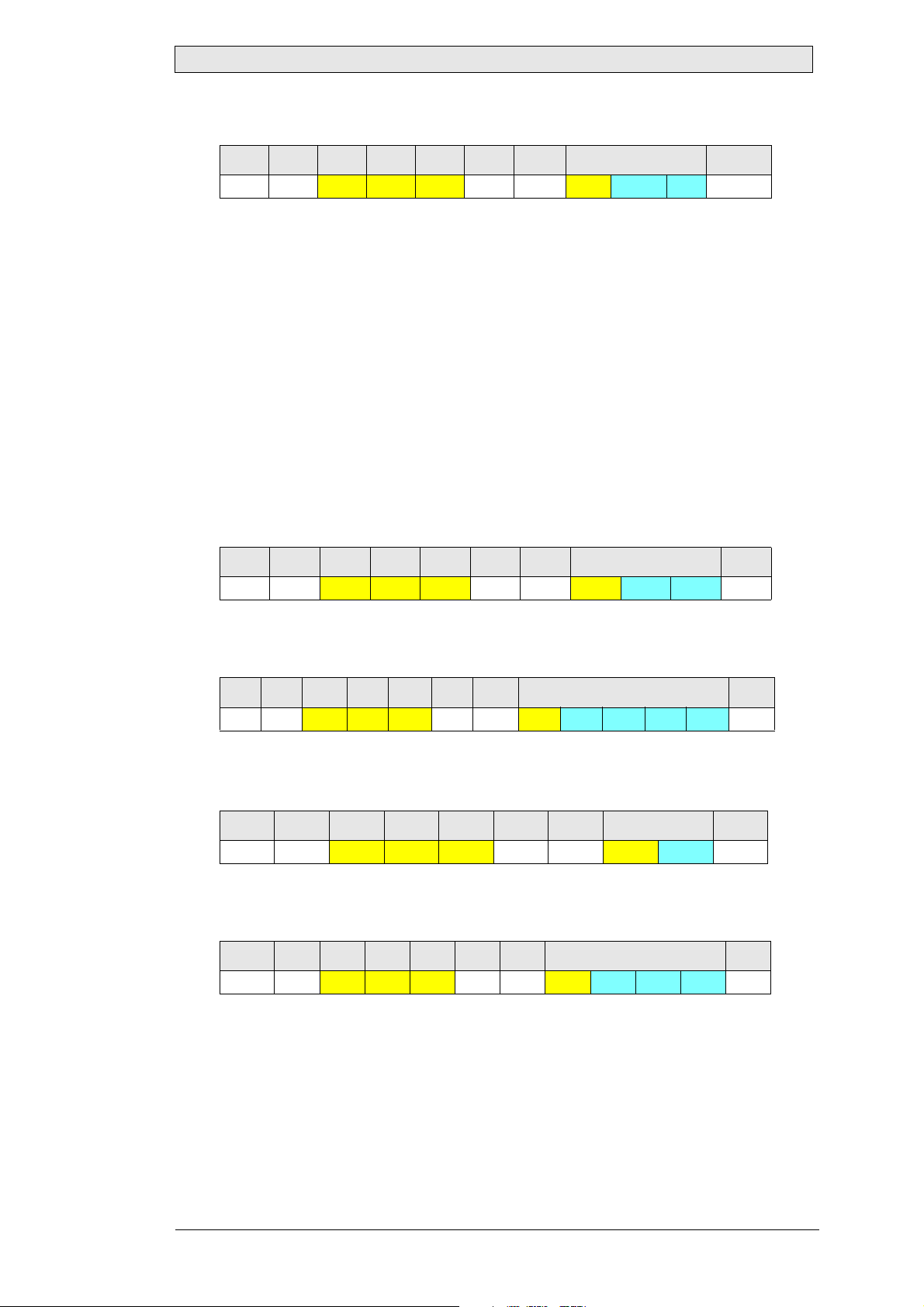
SCOM Message Basic Format
Byte
Field
01234567...7 + [LEN]
ATN ADR CMD LEN ICHKH DATA ICHKD
Each field of the message is described in the following table:
Byte Field Value Size Description
0ATN
1ADR
2
34CMD
0x07 (BELL):
Command
0x06 (ACK):
Acknowledge
0x15 (NAK):
Negative
Acknowledge
0x00 to 0xEF:
Monitor group/
address
0xFF:
Broadcast address
0xF0 to 0xFE:
Unused address
range
0x42 0x52 0x54:
“BRT”
0x4D 0x41 0x4E:
“MAN”
0x56 0x45 0x52:
“VER”
0x50 0x4F 0x54:
“POT”
0x4D 0x43 0x43:
“MCC”
0x54 0x59 0x50:
“TYP”
0x45 0x54 0x43:
“ETC”
0x4C 0x41 0x55:
“LAU”
1 byte
1 byte
3 bytes
Identifies the start of a new me ssage. Th e
type of message is given by its value. Data
transfer is always initiated by using the
Command message type. Depending on
the command, a response message of type
Acknowledge or Negative Acknowledge
may be sent back by the destination.
Defines the destination of a command
message or the source of the response
message. A unique monitor group/address
can be assigned to each monitor in a
network, and then individually addressed
using this field. By default, all monitors
also suppor t th e Br o adcast address an d
can be controlled simultaneously. In this
case, no response messages are sent.
Contains the main command supported in
the current firmware version.
Please refer to section Command
Reference for a description of commands
and sub-co mmands.
Beijer Electronics, MAEN975 11
Page 12

Message Format and Description
Byte Field Value Size Description
5LEN
6ICHKH... 1 byte
7
DATA ...
...
7 + [LEN] ICHKD ... 1 byte
0 to 74
(0x00 to 0x4A)
1 byte
0 to 74
bytes
82 bytes
The size of the DATA-field in bytes.
To protect the message header
(bytes 0 to 5), a simple 8-bit checksum is
calculated as follows:
Calculate the sum of bytes 0 to 5.
1.
Reduce the sum width to 8 bits
2.
(AND 0xFF).
3.
Invert all bits. The result is ICHKH.
The checksum is verified as follows:
Calculate the sum of bytes 0 to 6.
1.
Reduce the sum width to 8 bits (AND
2.
0xFF).
3.
The result should be 0xFF.
Optional field.
If the LEN-field is not 0, this f ield contains
sub-commands and/or data for the
specified command. If the LEN-field is 0,
no data is available.
Optional field. On l y sent if data is
available (LEN ≠ 0).
T o protect the data (bytes 7 to 7+(LEN-1)),
a simple 8-bit checksum is calculated as
follows:
1.
Calculate the sum of bytes 7 to
7+(LEN-1)
2.
Reduce the sum width to 8 bits (AND
0xFF)
3.
Invert all bits. The result is ICHKD.
The checksum is verified as follows:
1.
Calculate the sum of bytes 7 to 7+LEN
2.
Reduce the sum width to 8 bits (AND
0xFF)
3.
The result should be 0xFF
As shown in the table, the DATA field is optional, if the used command does not re-
quire any data. In this case the value of LEN is 0 and the minimum size of a SCOM
message 7 bytes (bytes 0 to 6), because field ICHKD is not sent.
If a command requires data to be sent, the maximum size of a SCOM message is 82
bytes. This means, that the last field ICHKD is located at the offset of the first data
byte plus the value of the LEN field.
The maximum value of the LEN field is 74, which is calculated as:
[LEN] = max. message size - (min. message size + ICHKD size)
or
82 - (7 + 1) = 74
12 Beijer Electronics, MAEN975
Page 13

Monitor Addressing
4 Monitor Addressing
By default, a Beijer Electronics MT230 Nautic Monitor supports the standard
SCOM addressing scheme, which allows a total count of 16 monitors within a network. The address of a monitor is set with four DIP switches. If a SCOM command
is sent to a monitor, the ADR field must contain either the broadcast address 0xFF,
or the address of the destination device set by the DIP switches. To eliminate this limit, a new addressing scheme is introduced first with Beijer Electronics MT230 Nautic
Monitors.
According to the previous chapter, the width of the ADR field is 1 byte (or 8 bits).
The standard SCOM addressing scheme uses only the lower 4 bits of this field (only
in case of the broadcast address, all bits are used), allowing a maximum of 16 addresses.
Related information
Message Format and Descri pt i on
The new addressing scheme, implemented in Beijer Electronics MT230 Nautic
Monitor, uses also the 4 upper bits. To distinguish between the standard and new addressing scheme, these bits are called “group bits” or simply “group”. Based on this
definition, the following table shows field ADR in more detail:
ADR bits 7...4 ADR bits 3...0
Group
(0 … 14)
Address
(0 … 15)
As shown in the table, a group between 0 and 14 can be specified. Group 15 is not
supported, to avoid address collision with the broadcast address. Thus, together with
the address field, a total count of 15 x 16 = 240 monitors can be connected to one
network.
Monitor grouping is activated only, if the monitor is set up to use the software configured address, instead of the hardware address specified by the DIP switches. If the
monitor uses the hardware address, the group address is automatically set to 0, regardless of the group configuration.
Beijer Electronics MT230 Nautic Monitor addresses are always given in a dotted notation as “group.address”. This means, if a monitor belongs to group 7 and its address
is 3, the resulting address will be 7.3, which is 115 (0x73). In the standard mode (i.e.
DIP switch address is used), the monitor address will be 0.3 (or simply 3) for the given example, because the group bits are set to 0.
If a Beijer Electronics MT230 Nautic Monitor is configured as remote controller, it
addresses always monitors within its own group. By definition, a Beijer Electronics
MT230 Nautic Monitor cannot remote control monitors in another group.
Beijer Electronics, MAEN975 13
Page 14

Protocol Description and Timings
5 Protocol Description and Timings
The protocol used for transferring SCOM messages and receiving response messages
is optimized for easy software implementation. Regardless of the type of interface, a
connected monitor is always passive and listening for a command to be received by
any available communication interface. A monitor never sends SCOM messages by
itself, unless it is configured as a remote controller.
If a monitor receives a SCOM message from any interface, it verifies the message and
checks the address field ADR. In case of an address match between the received address and the monitor address, the command is processed.
If the broadcast address 0xFF is received, a command is always processed by any
monitor in the network. Depending on the received address and the type of the interface, a response message (ACK or NAK) might be sent back to the interface, from
which the command was received.
If a monitor is individually addressed and a serial port (RS232 or RS485) is used, the
next command shall not be sent until a delay time called Inter-message gap. The
Inter-message gap depends on the baud rate and is calculated as shown below:
5 x 10
Ti =
b
Ti: Inter-message gap [s]
b: Baud rate [bits/second]
Example
Inter-message gap at 9600 baud: Ti = 5 x 10 / 9600 ≈ 0.0052 s = 5.2 ms
14 Beijer Electronics, MAEN975
Page 15

Protocol Description and Timings
Conditions for Response Message
The conditions for a response message generated by the monitor are described below:
Interface Address condition Co mmand status Response
RS232 Address does not match
monitor address
Address matches monitor
address
Address is Broadcast
address (0xFF)
RS485 Address does not match
monitor address
Address matches monitor
address
Address is Broadcast
address (0xFF)
Ethernet Address does not match
monitor address
Address matches monitor
address
Address is Broadcast
address (0xFF)
Delayed Response
not EXECUTED No response
not EXECUTED No response
if COMPLETED ACK
if FAILED NAK
if COMPLETED ACK
if FAILED NAK
not EXECUTED No response
not EXECUTED No response
if COMPLETED ACK
if FAILED NAK
if COMPLETED Delayed ACK
if FAILED No response
not EXECUTED No response
not EXECUTED No response
if COMPLETED ACK
if FAILED NAK
if COMPLETED No response
if FAILED No response
If a monitor receives a SCOM message with a broadcast address from the RS485 interface and the command is completed, the generated response message is sent after
a delay time. This is required, because many monitors can be attached to the RS485
bus, but only one monitor can claim the line for its communication. The delay guarantees that each response message is sent one after one, even if all monitors have received the broadcast message and processed it at the same time, avoiding a collision
on the RS485 bus.
The length of the delay time depends on the monitor address and maximum length
of a response message, and is calculated according to the following formula:
(2.5 + Lr) x 10 x N
Te =
b
Te: Broadcast command response [s]
Lr: Maximum length of response message
N: Monitor address + 1
b: Baud rate [bits/second]
Beijer Electronics, MAEN975 15
Page 16

Protocol Description and Timings
The Lr value depends on the command, for which the response message is generated.
Detailed information and the “Maximum Lr value” for each response message can be
found in Command Reference chapter.
Note:
The given “Maximum Lr value” is specified for a valid command. If an invalid command
with a data field exceeding the specification is sent, the Lr value will grow accordingly.
Related information
Command Reference
Example
Broadcast command response for command BRT, sent by monitor with address 7 at
9600 baud: Te = (2.5 + 9) x 10 x 8 / 9600 ≈ 0.0958 s ≈ 95.8 ms
The delay time Te is inserted by the monitor automatically, only if the RS485 interface is selected for the communication. If the RS232 interface is used, the response
message is generated and sent as fast as possible. This is true also for the Ethernet
communication, but the time when the response message is received depends actually
on the network load and speed.
The RS232 communication does not require a delay time due to the point-to-point
communication, where only two devices can be attached to the line (i.e. host and
monitor or monitor and monitor). Ethernet communication is similar to the RS485
communication, where many monitors can be attached to the same line. However,
in contrast to the RS485 interface, a collision is handled by the Ethernet architecture
and software, so there is no need for anti-collision support within the monitor.
16 Beijer Electronics, MAEN975
Page 17

Command Reference
6 Command Reference
The Lauer SCOM protocol exposes many commands for remote control of a Beijer
Electronics MT230 Nautic Monitor by a dedicated software. It supports all standard
SCOM commands, as well as the new Lauer command set for special purpose functions.
This chapter describes each SCOM command and sub-commands for the following
currently available monitor: Beijer Electronics MT230 Nautic Monitor
Beijer Electronics, MAEN975 17
Page 18
Command Reference
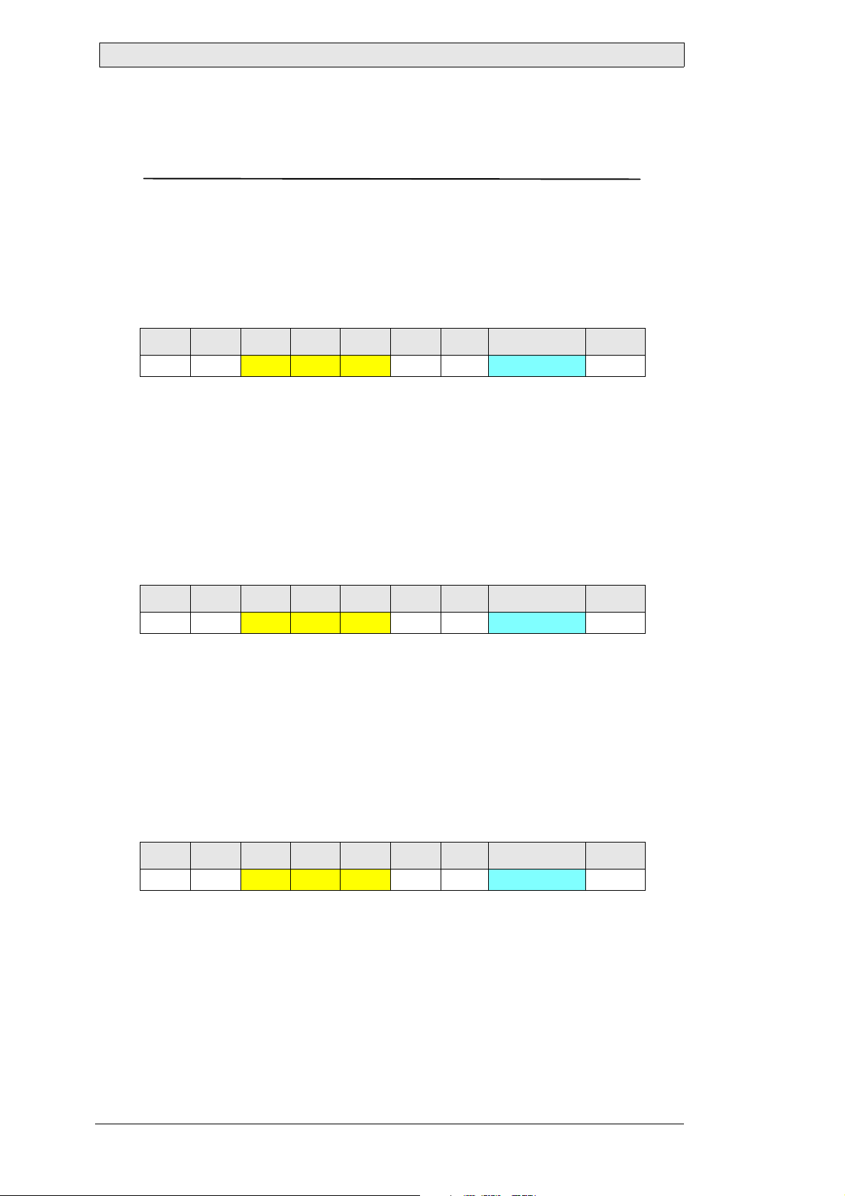
6.1 BRT
Backlight Brightness
Sets the backlight level to the given value. This command affects only the brightness
of the backlight lamp or LED array, not the brightness value of the video controller.
Supported since Firmware Version
MT230 Nautic Monitor: 1.0
Command Stream
0 1 2 3 4 5 6 7 8
0x07 ADR 0x42 0x52 0x54 0x01 ICHKH Backlight level ICHKD
Backlight level
Value: 0: dark … 255: bright
Type: Byte
Length: 1
Descript i on: New backlight level
Response Message (Ack n o wledge)
0 1 2 3 4 5 6 7 8
0x06 ADR
Backlight level
0x42 0x52 0x54 0x01 ICHKH Backlight level ICHKD
Value: 0: dark … 255: bright
Type: Byte
Length: 1
Descript i on: Cur r ent backlight level
Response Message (Negati v e Ack n owl ed g e)
0 1 2 3 4 5 6 7 8
0x15 ADR
Backlight level
0x42 0x52 0x54 0x01 ICHKH Backlight level ICHKD
Value: 0: dark … 255: bright
Type: Byte
Length: 1
Description: Last backlight level
18 Beijer Electronics, MAEN975
Page 19
Command Reference
Maximum Lr for this Command
9
Example 1
Set the backlight level of monitor at address 0.7 (group 0, address 7) to 130 (0x82):
0 1 2 3 4 5 6 7 8
0x07 0x07
0x42 0x52 0x54 0x01 0x08 0x82 0x7D
Monitor at address 0.7 (group 0, address 7) has acknowledged the new backlight level
130 (0x82):
0 1 2 3 4 5 6 7 8
0x06 0x07
0x42 0x52 0x54 0x01 0x09 0x82 0x7D
Example 2
Send an invalid “BRT” command to the monitor at address 0.7 (group 0, address 7).
The command has two data bytes, but “BRT” accepts only one byte:
0 1 2 3 4 5 6 7...8 9
0x07 0x07
0x42 0x52 0x54 0x02 0x07 0xFF 0xFF 0x01
Monitor at address 0.7 (group 0, address 7) has not accepted the command. Instead,
it sent a negative acknowledge with the current backlight level 128 (0x80). The
length of the response message exceeds the specified value 9, because of the invalid
data field length:
0 1 2 3 4 5 6 7...8 9
0x15 0x07
0x42 0x52 0x54 0x02 0xF9 0x80 0x00 0x7F
Beijer Electronics, MAEN975 19
Page 20
Command Reference
6.2 MAN
Manufacturer ID
Requests the manufacturer ID from the monitor. The manufacturer ID is a short,
max. 7 character ASCII-string containing the manufacturer specific code.
For monitors manufactured by Beijer Electronics, the returned code is always “LAU”.
Supported since Firmware Version
MT230 Nautic Monitor: 1.0
Command Stream
0 1 2 3 4 5 6
0x07 ADR
0x4D 0x41 0x4E 0x00 ICHKH
(This command has no data)
Response Message (Ack n o wledge)
0 1 2 3 4 5 6 7...7+[LEN]-1 7+[LEN]
0x06 ADR
Manufacturer ID
0x4D 0x41 0x4E LEN ICHKH Manufacturer ID ICHKD
Value: ASCII character s
Type: String
Length: 0...7
Description: ASCII-string containing the manufacturer ID
Response Message (Negati v e Ack n owl ed g e)
Under normal operation conditions, a device never sends a negative acknowledge in
response to this command.
Maximum Lr for this Command
15
Example
Query the manufacturer ID of the monitor at address 0.7 (group 0, address 7):
0 1 2 3 4 5 6
0x07 0x07 0x4D 0x41 0x4E 0x00 0x15
The monitor at address 0.7 (group 0, address 7) has returned “0x4C 0x41 0x55”,
which represents the ASCII-string “LAU”, indicating that the monitor is manufactured by Elektronik-Systeme Lauer GmbH & Co. KG:
0 1 2 3 4 5 6 7...9 10
0x06 0x07
20 Beijer Electronics, MAEN975
0x4D 0x41 0x4E 0x03 0x13 0x4C 0x41 0x55 0x1D
Page 21
Command Reference
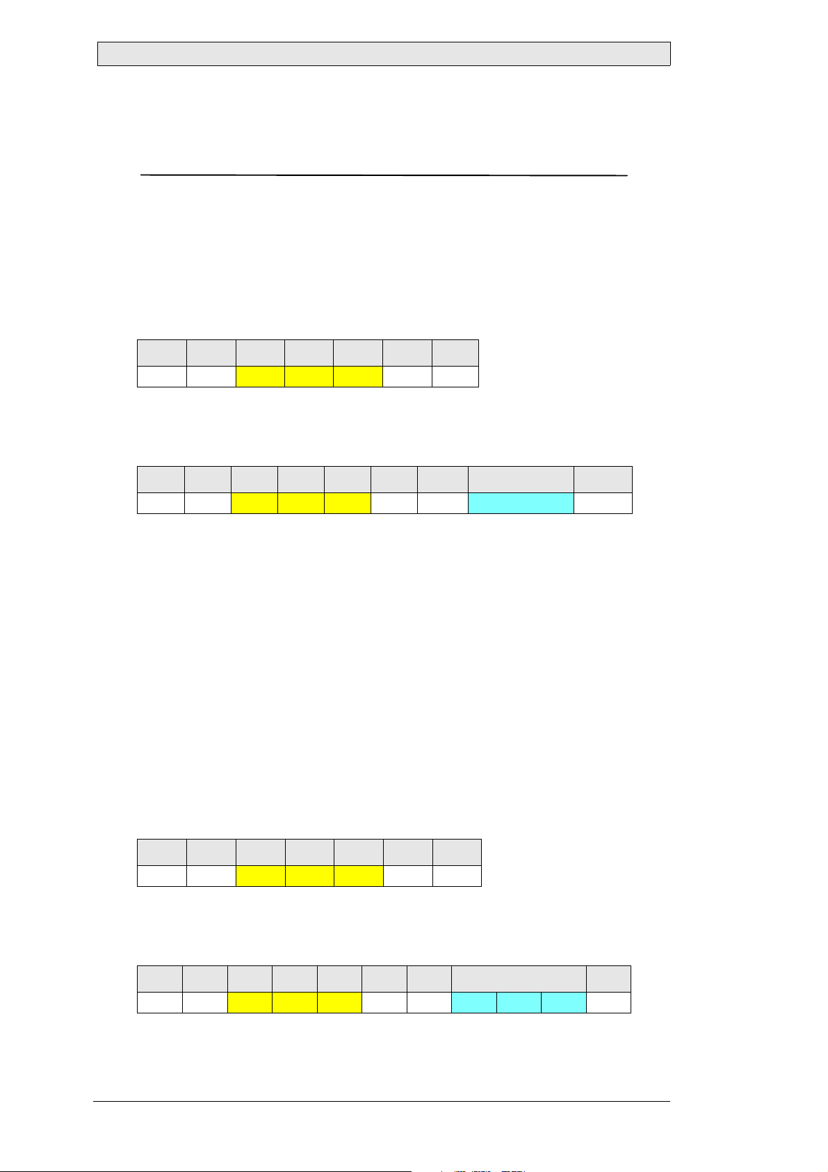
6.3 VER
Unit ID and Model / Version Number
Requests the preassigned unit ID and model code, and the version of the serial
communications interface software. For compatibility reasons, this code is always
static and does not return information specific to Beijer Electronics Nautic Monitors.
To get device informations specific to Beijer Electronics Nautic Monitors, such as
firmware version etc., use the Lauer Extension command “LAU”.
Supported since Firmware Version
MT230 Nautic Monitor: 1.0
Command Stream
0 1 2 3 4 5 6
0x07 ADR 0x56 0x45 0x52 0x00 ICHKH
(This command has no data)
Response Message (Acknowledge)
0 1 2 3 4 5 6 7...9 10
0x06 ADR
Unit ID / Version
0x56 0x45 0x52 0x03 ICHKH Unit ID / Version ICHKD
Value: 0…255 each byte
Type: Byte array
Length: 3
Description: Static unit ID, model and version number
Response Message (Negative Acknowledge)
Under normal operation conditions, a device never sends a negative acknowledge in
response to this command.
Maximum Lr for this Command
11
Example
Query the unit ID, model and version number of the monitor at address 0.7 (group
0, address 7):
0 1 2 3 4 5 6
0x07 0x07 0x56 0x45 0x52 0x00 0x04
The monitor at address 0.7 (group 0, address 7) has returned “0x01 0x01 0x00”,
which indicates model 1, version 1.0:
0 1 2 3 4 5 6 7...9 10
0x06 0x07 0x56 0x45 0x52 0x03 0x02 0x01 0x01 0x00 0xFD
Beijer Electronics, MAEN975 21
Page 22
Command Reference
6.4 POT
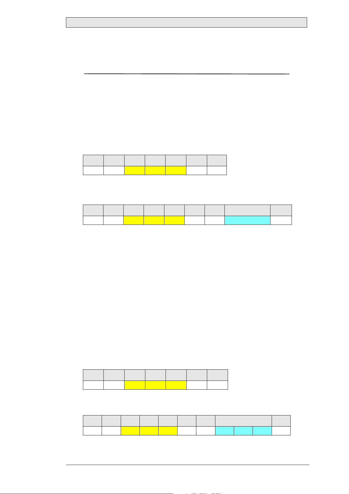
Local Control
Enables or disables the local backlight level control. If the local backlight control is
enabled, the backlight level can be changed using the front panel buttons and by remote control (serial or Ethernet interface, analog or digital input). If the local backlight control is disabled, the backlight level cannot be changed using the front panel
buttons. It can be still changed by any remote control option.
Supported since Firmware Version
MT230 Nautic Monitor: 1.0
Command Stream
0 1 2 3 4 5 6 7 8
0x07 ADR 0x50 0x4F 0x54 0x01 ICHKH Local control ICHKD
Local control
Value: 0x00: Disable loca l control 0xFF: Enable local control
Type: Byte
Length: 1
Description: New local control configuration
Response Message (Ack n o wledge)
0 1 2 3 4 5 6 7 8
0x06 ADR
Local control
0x50 0x4F 0x54 0x01 ICHKH Local control ICHKD
Value: 0x00: Local control disabled 0xFF: Local control enabled
Type: Byte
Length: 1
Description: Current local control configuration
Response Message (Negati v e Ack n owl ed g e)
0 1 2 3 4 5 6 7 8
0x15 ADR
Local control
22 Beijer Electronics, MAEN975
0x50 0x4F 0x54 0x01 ICHKH Local control ICHKD
Value: 0x00: Local control disabled 0xFF: Local control enabled
Type: Byte
Length: 1
Description: Last local control configuration
Page 23
Command Reference
Maximum Lr for this Command
9
Example 1
Disable the local control of monitor at address 0.7 (group 0, address 7):
0 1 2 3 4 5 6 7 8
0x07 0x07
0x50 0x4F 0x54 0x01 0xFD 0x00 0xFF
Monitor at address 0.7 (group 0, address 7) has acknowledged, that the local control
is disabled:
0 1 2 3 4 5 6 7 8
0x06 0x07
0x50 0x4F 0x54 0x01 0xFE 0x00 0xFF
Example 2
Send an invalid “POT” command to the monitor at address 0.7 (group 0, address 7).
The command uses an invalid value 0x90 for “Local control”:
0 1 2 3 4 5 6 7 8
0x07 0x07
0x50 0x4F 0x54 0x01 0xFD 0x90 0x6F
Monitor at address 0.7 (group 0, address 7) has not accepted the command. Instead,
it sent a negative acknowledge with the current local control mode 255 (0xFF):
0 1 2 3 4 5 6 7 8
0x15 0x07
0x50 0x4F 0x54 0x01 0xEF 0xFF 0x00
Beijer Electronics, MAEN975 23
Page 24
Command Reference
6.5 MCC
Unit Control Command
This command is used for remote configuration of the video controller within the
monitor. The video controller is an independent device, which controls the LCD
panel. Because each monitor model can be equipped with different kind of LCD
panel (size, resolution, type etc.), the used video controller can be also different from
model to model.
The MCC command is a container for video controller specific commands. These so
called sub-commands and their parameters, if available, are encapsulated within the
DATA field of the command stream. The base command stream is always the same
on each monitor model, while the specific video controller commands and parameters are hardware dependant and may not be supported by any model.
A MCC sub-command may specify an operation type as its parameter, which actually
indicates what to do. An operation type is an optional parameter. Generally, the following operation types are available:
Operation type Parameter value Description
ABSOLUTE An ASCII-encoded
hexadecimal value
INC “+” Increments the current value of the selected
DEC “-” Decrements the current value of the selected
RESET “r” or “R” Resets the value of the selected video controller
QUER Y “?” Queries the current value of the selected video
Sets the selected video controller setting to the
given value.
video controller setting.
video controller setting.
setting to an internally predefined value.
controller setting.
If an absolute value is specified as parameter, it is always encoded as an hexadecimal
ASCII-string. This applies also to the returned response messages, whenever a value
is available. The returned response message contains always the sub-command and
its parameter, which was sent with the command stream. Additional data is simply
appended by the monitor after the sub-command and parameter.
Thus, for any MCC sub-command, the following command and response streams
are generally common:
Command Stream
0 1 2 3 4 5 6 7...7+[LEN]-1 7+[LEN]
0x07 ADR
SCMD / Param
24 Beijer Electronics, MAEN975
0x4D 0x43 0x43 LEN ICHKH SCMD Param ICHKD
Video controller specific sub-command and parameter(s ), if av aila ble
Page 25

Command Reference
Response Message (Acknowledge)
0 1 2 3 4 5 6 7...7+[LEN]-1 7+[LEN]
0x06 ADR 0x4D 0x43 0x43 LEN ICHKH SCMD Param Ret ICHKD
SCMD / Param
Video controller specific sub-command and parameter(s), sent with the
command stream
Ret
Data returned by the monitor, i.e. current value of the selected video
controller setting
Response Message (Negative Acknowledge)
Under normal operation conditions, a device never sends a negative acknowledge in
response to this command.
MCC Sub-commands
All supported MCC sub-commands are described in the following sections.
Beijer Electronics, MAEN975 25
Page 26
Command Reference
6.6 MCC_BRIGHTNESS (0x81)
Brightness
Adjusts or queries the brightness value of the video controller. This command affects
only the brightness of the video controller, not the brightness of the backlight lamp
or LED array.
Supported since Firmware Version
MT230 Nautic Monitor: 1.0
Command Stream
0 1 2 3 4 5 6 7...7+[LEN]-1 7+[LEN]
0x07 ADR
Param: ABSOLUTE
Value: “00”: dark … “FF”: bright
Type: Two-digit ASCII-encoded hexadecimal number
Length: 2
Description: New brightness level
Param: INC
V alue: “+” (0x2B)
Type: ASCII character
Length: 1
Description: Increment the current brightness value
Param: DEC
Value: “-” (0x2D)
Type: ASCII character
Length: 1
Description: Decrement the current brightness value
Param: RESET
Value: “R” or “r” (0x52 or 0x72)
Type: ASCII character
Length: 1
Description: Reset the brightness to an internally predefined value
Param: QUERY
Value: “?” (0x3 F)
Type: ASCII character
Length: 1
Description: Query the current brightness value
0x4D 0x43 0x43 LEN ICHKH 0x81 Param ICHKD
26 Beijer Electronics, MAEN975
Page 27
Command Reference
Response Message (Acknowledge)
0 1 2 3 4 5 6 7...7+[LEN]-1 7+[LEN]
0x06 ADR 0x4D 0x43 0x43 LEN ICHKH 0x81 Param Ret ICHKD
Ret
Value: “00”: dark … “FF”: bright
Type: Two-digit ASCII-encoded hexadecimal number
Length: 2
Description: Current brightness value
Maximum Lr for this Command
13
Example 1
Set the brightness level of monitor at address 0.7 (group 0, address 7) to 200 (the
hexadecimal value of 200 is 0xC8, which is represented in ASCII as “C8” and split
into two ASCII codes as 0x43 0x38):
0 1 2 3 4 5 6 7...9 10
0x07 0x07
0x4D 0x43 0x43 0x03 0x1B 0x81 0x43 0x38 0x03
Monitor at address 0.7 (group 0, address 7) has acknowledged the new brightness level 130 (0x82):
0 1 2 3 4 5 6 7...11 12
0x06 0x07
0x4D 0x43 0x43 0x05 0x1A 0x81 0x43 0x38 0x43 0x38 0x7D
Example 2
Query the current brightness level of monitor at address 0.7 (group 0, address 7):
0 1 2 3 4 5 6 7...8 9
0x07 0x07
0x4D 0x43 0x43 0x02 0x1C 0x81 0x3F 0x3F
Monitor at address 0.7 (group 0, address 7) has returned the current brightness level
200 (0xC8):
0 1 2 3 4 5 6 7...10 11
0x06 0x07
0x4D 0x43 0x43 0x04 0x1B 0x81 0x3F 0x43 0x38 0xC4
Beijer Electronics, MAEN975 27
Page 28
Command Reference
Example 3
Increment the current brightness level of monitor at address 0.7 (group 0, address 7):
0 1 2 3 4 5 6 7...8 9
0x07 0x07 0x4D 0x43 0x43 0x02 0x1C 0x81 0x2B 0x53
Monitor at address 0.7 (group 0, address 7) has returned the new brightness level 201
(0xC9):
0 1 2 3 4 5 6 7...10 11
0x06 0x07 0x4D 0x43 0x43 0x04 0x1B 0x81 0x2B 0x43 0x39 0xD7
Example 4
Reset the brightness level of monitor at address 0.7 (group 0, address 7):
0 1 2 3 4 5 6 7...8 9
0x07 0x07
0x4D 0x43 0x43 0x02 0x1C 0x81 0x52 0x2C
Monitor at address 0.7 (group 0, address 7) has returned the default brightness level
128 (0x80):
0 1 2 3 4 5 6 7...10 11
0x06 0x07
0x4D 0x43 0x43 0x04 0x1B 0x81 0x82 0x38 0x30 0xC4
28 Beijer Electronics, MAEN975
Page 29
Command Reference
6.7 MCC_CONTRAST (0x82)
Contrast
Adjusts or queries the contrast value of the video controller.
Supported since Firmware Version
MT230 Nautic Monitor: 1.0
Command Stream
0 1 2 3 4 5 6 7...7+[LEN]-1 7+[LEN]
0x07 ADR
Ext:
Param: ABSOLUTE
Param: INC
Param: DEC
Param: RESET
Param: QUERY
0x4D 0x43 0x43 LEN ICHKH 0x82 Ext Ret ICHKD
Value: “A” or “a” (0x41 or 0x61)
Type: ASCII character
Length: 1
Description: Command extension.
Value: “00”: low … “FF”: high
Type: Two-digit ASCII-encoded hexadecimal number
Length: 2
Description: New contrast value
Value: “+” (0x2B)
Type: ASCII character
Length: 1
Description: Increment the current contrast value
Value: “-” (0x2D)
Type: ASCII character
Length: 1
Description: Decrement the current contrast value
Value: “R” or “r” (0x52 or 0x72)
Type: ASCII character
Length: 1
Descripti o n: Reset the contr a st to an internally pr edefined val ue
Value: “?” (0x3F)
Type: ASCII character
Length: 1
Description: Query the current contrast value
This character must be always sen t as part of t h e sub command.
Beijer Electronics, MAEN975 29
Page 30
Command Reference
Response Message (Ack n o wledge)
0 1 2 3 4 5 6 7...7+[LEN]-1 7+[LEN]
0x06 ADR 0x4D 0x43 0x43 LEN ICHKH 0x82 Ext Param Ret ICHKD
Ret
Value: “00”: low … “FF”: high
Type: Two-digit ASCII-encoded hexadecimal number
Length: 2
Description: Current contrast value
Maximum Lr for this Command
14
Example 1
Set the contrast level of monitor at address 0.7 (group 0, address 7) to 150 (the hexadecimal value of 150 is 0x96, which is represented in ASCII as “96” and split into
two ASCII codes as 0x35 0x41):
0 1 2 3 4 5 6 7...10 11
0x07 0x07
0x4D 0x43 0x43 0x04 0x1A 0x82 0x41 0x39 0x36 0xCD
Monitor at address 0.7 (group 0, address 7) has acknowledged the new contrast level
100 (0x64):
0 1 2 3 4 5 6 7...12 13
0x06 0x07
0x4D 0x43 0x43 0x06 0x19 0x82 0x41 0x39 0x36 0x39 0x36 0x5E
Example 2
Query the current contrast level of monitor at address 0.7 (group 0, address 7):
0 1 2 3 4 5 6 7...9 10
0x07 0x07
0x4D 0x43 0x43 0x03 0x1B 0x82 0x41 0x3F 0xFD
Monitor at address 0.7 (group 0, address 7) has returned the current contrast level
197 (0xC5):
0 1 2 3 4 5 6 7...11 12
0x06 0x07
0x4D 0x43 0x43 0x05 0x1A 0x82 0x41 0x3F 0x43 0x35 0x85
30 Beijer Electronics, MAEN975
Page 31

Command Reference
Example 3
Decrement the current contrast level of monitor at address 0.7 (group 0, address 7):
0 1 2 3 4 5 6 7...9 10
0x07 0x07 0x4D 0x43 0x43 0x03 0x1B 0x82 0x41 0x2D 0x0F
Monitor at address 0.7 (group 0, address 7) has returned the new contrast level 196
(0xC4):
0 1 2 3 4 5 6 7...11 12
0x06 0x07 0x4D 0x43 0x43 0x05 0x1A 0x82 0x41 0x2D 0x43 0x34 0x98
Example 4
Reset the contrast level of monitor at address 0.7 (group 0, address 7):
0 1 2 3 4 5 6 7...9 10
0x07 0x07
0x4D 0x43 0x43 0x03 0x1B 0x82 0x41 0x52 0xEA
Monitor at address 0.7 (group 0, address 7) has returned the default contrast level
128 (0x80):
0 1 2 3 4 5 6 7...11 12
0x06 0x07
0x4D 0x43 0x43 0x05 0x1A 0x82 0x41 0x52 0x38 0x30 0x82
Beijer Electronics, MAEN975 31
Page 32

Command Reference
6.8 MCC_SCALINGMODE (0x8C)
Scaling Mode
Sets or queries the main scaling mode.
Supported since Firmware Version
MT230 Nautic Monitor: 1.0
Command Stream
0 1 2 3 4 5 6 7...7+[LEN]-1 7+[LEN]
0x07 ADR
Param: QUERY
Value: “?” (0x3 F)
Type: ASCII character
Length: 1
Description: Query the current scaling mode
0x4D 0x43 0x43 LEN ICHKH 0x8C Param ICHKD
32 Beijer Electronics, MAEN975
Page 33

Command Reference
Response Message (Acknowledge)
0 1 2 3 4 5 6 7...7+[LEN]-1 7+[LEN]
0x06 ADR 0x4D 0x43 0x43 LEN ICHKH 0x8C Param Ret ICHKD
Ret
Value: “0”: One to one
“1”: Fill all
“2”: Fill aspect ratio
Type: One-digit ASCII-encoded hexadecimal number
Length: 1
Description: Current scaling mode
Maximum Lr for this Command
11
Example
Query the current scaling mode of monitor at address 0.15 (group 0, address 15):
0 1 2 3 4 5 6 7...8 9
0x07 0x0F 0x4D 0x43 0x43 0x02 0x14 0x8C 0x3F 0x34
Monitor at address 0.15 (group 0, address 15) has returned the current scaling mode
“One to one” (which is ASCII “0” with ASCII-code 0x30):
0 1 2 3 4 5 6 7...9 10
0x06 0x0F
0x4D 0x43 0x43 0x03 0x14 0x8C 0x3F 0x30 0x04
Beijer Electronics, MAEN975 33
Page 34

Command Reference
6.9 MCC_GAMMAVALUE (0x9D)
Gamma Value
Sets or queries the gamma value.
Supported since Firmware Version
MT230 Nautic Monitor: 1.0
Command Stream
0 1 2 3 4 5 6 7...7+[LEN]-1 7+[LEN]
0x07 ADR
Param: ABSOLUTE
Value: “0”: Linear
Type: One-digit ASCII-encoded hexadecimal number
Length: 1
Description: New gamma value
Param: RESET
Value: “R” or “r” (0x52 or 0x72)
Type: ASCII character
Length: 1
Description: Reset the gamma setting to an internally predefined value
Param: QUERY
Value: “?” (0x3 F)
Type: ASCII character
Length: 1
Description: Query the current gamma value
0x4D 0x43 0x43 LEN ICHKH 0x9D Param ICHKD
“1”: CRT
Response Message (Ack n o wledge)
0 1 2 3 4 5 6 7...7+[LEN]-1 7+[LEN]
0x06 ADR
Ret
0x4D 0x43 0x43 LEN ICHKH 0x9D Param Ret ICHKD
Value: “0”: Linear
“1”: CRT
Type: One-digit ASCII-encoded hexadecimal number
Length: 1
Description: Current gamma value
Maximum Lr for this Command
11
34 Beijer Electronics, MAEN975
Page 35

Command Reference
Example 1
Set the gamma value of monitor at address 0.7 (group 0, address 7) to “CRT” (which
is ASCII “1” with ASCII-codes 0x31):
0 1 2 3 4 5 6 7...8 9
0x07 0x07
0x4D 0x43 0x43 0x02 0x1C 0x9D 0x31 0x31
Monitor at address 0.7 (group 0, address 7) has acknowledged the new gamma value
“CRT” (0x31):
0 1 2 3 4 5 6 7...9 10
0x06 0x07
0x4D 0x43 0x43 0x03 0x01C 0x9D 0x31 0x31 0x00
Example 2
Query the current gamma value of monitor at address 0.7 (group 0, address 7):
0 1 2 3 4 5 6 7...8 9
0x07 0x07 0x4D 0x43 0x43 0x02 0x1C 0x9D 0x31 0x23
Monitor at address 0.7 (group 0, address 7) has returned the current gamma value
“CRT” (which is ASCII “1” with ASCII-code 0x31)
0 1 2 3 4 5 6 7...9 10
0x06 0x07 0x4D 0x43 0x43 0x03 0x1C 0x9D 0x3F 0x31 0xF2
Example 3
Reset the gamma value of monitor at address 0.7 (group 0, address 7):
0 1 2 3 4 5 6 7...8 9
0x07 0x07 0x4D 0x43 0x43 0x02 0x1C 0x9D 0x52 0x10
Monitor at address 0.7 (group 0, address 7) has returned the default gamma value
“Linear” (which is ASCII “0” with ASCII-code 0x30)
0 1 2 3 4 5 6 7...9 10
0x06 0x07
0x4D 0x43 0x43 0x03 0x1C 0x9D 0x52 0x30 0xE0
Beijer Electronics, MAEN975 35
Page 36

Command Reference
6.10 MCC_COLOURTEMP (0xB3)
Color Temperature
Sets or queries the current color temperature.
Supported since Firmware Version
MT230 Nautic Monitor: 1.0
Command Stream
0 1 2 3 4 5 6 7...7+[LEN]-1 7+[LEN]
0x07 ADR
Param: ABSOLUTE
Value: “0”: 9300K
Type: One-digit ASCII-encoded hexadecimal number
Length: 1
Description: New color temperature
Param: RESET
Value: “R” or “r” (0x52 or 0x72)
Type: ASCII character
Length: 1
Description: Reset the color temperature to an internally predefi ned va lue
Param: QUERY
Value: “?” (0x3F)
Type: ASCII character
Length: 1
Description: Query the current color temperature
0x4D 0x43 0x43 LEN ICHKH 0xB3 Param ICHKD
“1”: 7300K
“3”: 5000K
“4”: USER
Response Message (Ack n o wledge)
0 1 2 3 4 5 6 7...7+[LEN]-1 7+[LEN]
0x06 ADR 0x4D 0x43 0x43 LEN ICHKH 0xB3 Param Ret ICHKD
Ret
Value: “0”: 9300K
“1”: 7300K
“3”: 5000K
“4”: USER
Type: One-digit ASCII-encoded hexadecimal number
Length: 1
Description: Current color temperature
36 Beijer Electronics, MAEN975
Page 37

Command Reference
Maximum Lr for this Command
11
Example 1
Set the colour temperature of monitor at address 0.15 (group 0, address 15) to
“5000K” (which is ASCII “3” with ASCII-code 0x33):
0 1 2 3 4 5 6 7...8 9
0x07 0x0F
0x4D 0x43 0x43 0x02 0x14 0xB3 0x33 0x19
Monitor at address 0.15 (group 0, address 15) has acknowledged the new colour temperature “5000K” (0x33):
0 1 2 3 4 5 6 7...9 10
0x06 0x0F
0x4D 0x43 0x43 0x03 0x14 0xB3 0x33 0x33 0xE6
Example 2
Query the colour temperature of monitor at address 0.15 (group 0, address 15):
0 1 2 3 4 5 6 7...8 9
0x07 0x0F
0x4D 0x43 0x43 0x02 0x14 0xB3 0x3F 0x0D
Monitor at address 0.15 (group 0, address 15) has returned the colour temperature
“5000K” (which is ASCII “3” with ASCII-code 0x33):
0 1 2 3 4 5 6 7...9 10
0x06 0x0F
0x4D 0x43 0x43 0x03 0x14 0xB3 0x33 0x33 0xDA
Beijer Electronics, MAEN975 37
Page 38
Command Reference
6.11 MCC_REDLEVEL (0xB4)
Red Channel Level
Adjusts the level of the red channel.
Supported since Firmware Version
MT230 Nautic Monitor: 1.0
Command Stream
0 1 2 3 4 5 6 7...7+[LEN]-1 7+[LEN]
0x07 ADR
Param: ABSOLUTE
Value: “00”: low...“FF”: high
Type: Two-digit ASCII-encoded hexadecimal number
Length: 2
Description: New value for the red channel
Param: INC
V alue: “+” (0x2B)
Type: ASCII character
Length: 1
Description: Increment the current value of the red channel
Param: DEC
V alue: “-” (0x2D)
Type: ASCII character
Length: 1
Description: Decrement the current value of the red channel
Param: RESET
Value: “R” or “r” (0x52 or 0x72)
Type: ASCII character
Length: 1
Description: Reset the valu e of the red channel to an internally
Param: QUERY
Value: “?” (0x3 F)
Type: ASCII character
Length: 1
Description: Query the current value of the red channel
0x4D 0x43 0x43 LEN ICHKH 0xB4 Param ICHKD
predefined value
38 Beijer Electronics, MAEN975
Page 39

Command Reference
Response Message (Acknowledge)
0 1 2 3 4 5 6 7...7+[LEN]-1 7+[LEN]
0x06 ADR 0x4D 0x43 0x43 LEN ICHKH 0xB4 Param Ret ICHKD
Ret
Value: “00”: low...“FF”: high
Type: Two-digit ASCII-encoded hexadecimal number
Length: 2
Description: Current value of the red channel
Maximum Lr for this Command
13
Example 1
Set the red channel level of monitor at address 0.7 (group 0, address 7) to 190 (the
hexadecimal value of 190 is 0xBE, which is represented in ASCII as “BE” and split
into two ASCII codes as 0x42 0x45):
0 1 2 3 4 5 6 7...9 10
0x07 0x07
0x4D 0x43 0x43 0x03 0x1B 0xB4 0x42 0x45 0xC4
Monitor at address 0.7 (group 0, address 7) has acknowledged the new red channel
level 190 (0xBE):
0 1 2 3 4 5 6 7...11 12
0x06 0x07
0x4D 0x43 0x43 0x05 0x1A 0xB4 0x42 0x45 0x42 0x45 0x3D
Example 2
Query the current red channel level of monitor at address 0.7 (group 0, address 7):
0 1 2 3 4 5 6 7...8 9
0x07 0x07
0x4D 0x43 0x43 0x02 0x1C 0xB4 0x3F 0x0C
Monitor at address 0.7 (group 0, address 7) has returned the current red channel level
190 (0xBE):
0 1 2 3 4 5 6 7...10 11
0x06 0x07
0x4D 0x43 0x43 0x04 0x1B 0xB4 0x3F 0x42 0x45 0x85
Beijer Electronics, MAEN975 39
Page 40

Command Reference
Example 3
Decrement the current red channel level of monitor at address 0.7 (group 0, address
7):
0 1 2 3 4 5 6 7...8 9
0x07 0x07
0x4D 0x43 0x43 0x02 0x1C 0xB4 0x2D 0x1E
Monitor at address 0.7 (group 0, address 7) has returned the new red channel level
189 (0xBD):
0 1 2 3 4 5 6 7...10 11
0x06 0x07
0x4D 0x43 0x43 0x04 0x1B 0xB4 0x2D 0x42 0x44 0x98
Example 4
Reset the red channel level of monitor at address 0.7 (group 0, address 7):
0 1 2 3 4 5 6 7...8 9
0x07 0x07 0x4D 0x43 0x43 0x02 0x1C 0xB4 0x52 0xF9
Monitor at address 0.7 (group 0, address 7) has returned the default red channel level
128 (0x80):
0 1 2 3 4 5 6 7...10 11
0x06 0x07 0x4D 0x43 0x43 0x04 0x1B 0xB4 0x53 0x38 0x30 0x91
40 Beijer Electronics, MAEN975
Page 41

Command Reference
6.12 MCC_GREENLEVEL (0xB5)
Green Channel Leve l
Adjusts the level of the green channel.
Supported since Firmware Version
MT230 Nautic Monitor: 1.0
Command Stream
0 1 2 3 4 5 6 7...7+[LEN]-1 7+[LEN]
0x07 ADR
Param: ABSOLUTE
Value: “00”: low...“FF”: high
Type: Two-digit ASCII-encoded hexadecimal number
Length: 2
Description: New value for the green channel
Param: INC
Value: “+” (0x2B)
Type: ASCII character
Length: 1
Description: Increment the current value of the green channel
Param: DEC
Value: “-” (0x2D)
Type: ASCII character
Length: 1
Description: Decrement the current value of the green channel
Param: RESET
Value: “R” or “r” (0x52 or 0x72)
Type: ASCII character
Length: 1
Description: Reset the value of the green channel to an internally
Param: QUERY
Value: “?” (0x3F)
Type: ASCII character
Length: 1
Description: Query the current value of the green channel
0x4D 0x43 0x43 LEN ICHKH 0xB5 Param ICHKD
predefined value
Beijer Electronics, MAEN975 41
Page 42

Command Reference
Response Message (Ack n o wledge)
0 1 2 3 4 5 6 7...7+[LEN]-1 7+[LEN]
0x06 ADR 0x4D 0x43 0x43 LEN ICHKH 0xB5 Param Ret ICHKD
Ret
Value: “00”: low...“FF”: high
Type: Two-digit ASCII-encoded hexadecimal number
Length: 2
Description: Current value of the green channel
Maximum Lr for this Command
13
Example 1
Set the green channel level of monitor at address 0.7 (group 0, address 7) to 190 (the
hexadecimal value of 190 is 0xBE, which is represented in ASCII as “BE” and split
into two ASCII codes as 0x42 0x45):
0 1 2 3 4 5 6 7...9 10
0x07 0x07
0x4D 0x43 0x43 0x03 0x1B 0xB5 0x42 0x45 0xC3
Monitor at address 0.7 (group 0, address 7) has acknowledged the new green channel
level 190 (0xBE):
0 1 2 3 4 5 6 7...11 12
0x06 0x07
0x4D 0x43 0x43 0x05 0x1A 0xB5 0x42 0x45 0x42 0x45 0x3C
Example 2
Query the current green channel level of monitor at address 0.7 (group 0, address 7):
0 1 2 3 4 5 6 7...8 9
0x07 0x07
0x4D 0x43 0x43 0x02 0x1C 0xB5 0x3F 0x0B
Monitor at address 0.7 (group 0, address 7) has returned the current green channel
level 190 (0xBE):
0 1 2 3 4 5 6 7...10 11
0x06 0x07
0x4D 0x43 0x43 0x04 0x1B 0xB5 0x3F 0x42 0x45 0x84
42 Beijer Electronics, MAEN975
Page 43
Command Reference
Example 3
Increment the current green channel level of monitor at address 0.7 (group 0, address
7):
0 1 2 3 4 5 6 7...8 9
0x07 0x07
0x4D 0x43 0x43 0x02 0x1C 0xB5 0x2B 0x1F
Monitor at address 0.7 (group 0, address 7) has returned the new green channel level
191 (0xBD):
0 1 2 3 4 5 6 7...10 11
0x06 0x07
0x4D 0x43 0x43 0x04 0x1B 0xB5 0x2B 0x42 0x46 0x97
Example 4
Reset the green channel level of monitor at address 0.7 (group 0, address 7):
0 1 2 3 4 5 6 7...8 9
0x07 0x07 0x4D 0x43 0x43 0x02 0x1C 0xB5 0x52 0xF8
Monitor at address 0.7 (group 0, address 7) has returned the default green channel
level 128 (0x80):
0 1 2 3 4 5 6 7...10 11
0x06 0x07 0x4D 0x43 0x43 0x04 0x1B 0xB5 0x52 0x38 0x30 0x90
Beijer Electronics, MAEN975 43
Page 44

Command Reference
6.13 MCC_BLUELEVEL (0xB6)
Blue Channel Level
Adjusts the level of the blue channel.
Supported since Firmware Version
MT230 Nautic Monitor: 1.0
Command Stream
0 1 2 3 4 5 6 7...7+[LEN]-1 7+[LEN]
0x07 ADR
Param: ABSOLUTE
Value: “00”: low...“FF”: high
Type: Two-digit ASCII-encoded hexadecimal number
Length: 2
Description: New value for the blue channel
Param: INC
V alue: “+” (0x2B)
Type: ASCII character
Length: 1
Description: Increment the current value of the blue channel
Param: DEC
V alue: “-” (0x2D)
Type: ASCII character
Length: 1
Description: Decrement the current value of the blue channel
Param: RESET
Value: “R” or “r” (0x52 or 0x72)
Type: ASCII character
Length: 1
Description: Reset the va lu e of the blue channel to an internally
Param: QUERY
Value: “?” (0x3 F)
Type: ASCII character
Length: 1
Description: Query the current value of the blue channel
0x4D 0x43 0x43 LEN ICHKH 0xB6 Param ICHKD
predefined value
44 Beijer Electronics, MAEN975
Page 45

Command Reference
Response Message (Acknowledge)
0 1 2 3 4 5 6 7...7+[LEN]-1 7+[LEN]
0x06 ADR 0x4D 0x43 0x43 LEN ICHKH 0xB6 Param Ret ICHKD
Ret
Value: “00”: low...“FF”: high
Type: Two-digit ASCII-encoded hexadecimal number
Length: 2
Description: Current value of the blue channel
Maximum Lr for this Command
13
Example 1
Set the blue channel level of monitor at address 0.7 (group 0, address 7) to 190 (the
hexadecimal value of 190 is 0xBE, which is represented in ASCII as “BE” and split
into two ASCII codes as 0x42 0x45):
0 1 2 3 4 5 6 7...9 10
0x07 0x07
0x4D 0x43 0x43 0x03 0x1B 0xB6 0x42 0x45 0xC2
Monitor at address 0.7 (group 0, address 7) has acknowledged the new blue channel
level 190 (0xBE):
0 1 2 3 4 5 6 7...11 12
0x06 0x07
0x4D 0x43 0x43 0x05 0x1A 0xB6 0x42 0x45 0x42 0x45 0x3B
Example 2
Query the current blue channel level of monitor at address 0.7 (group 0, address 7):
0 1 2 3 4 5 6 7...8 9
0x07 0x07
0x4D 0x43 0x43 0x02 0x1C 0xB6 0x3F 0x0A
Monitor at address 0.7 (group 0, address 7) has returned the current green channel
level 190 (0xBE):
0 1 2 3 4 5 6 7...10 11
0x06 0x07
0x4D 0x43 0x43 0x04 0x1B 0xB6 0x3F 0x42 0x45 0x83
Beijer Electronics, MAEN975 45
Page 46

Command Reference
Example 3
Decrement the current blue channel level of monitor at address 0.7 (group 0, address
7):
0 1 2 3 4 5 6 7...8 9
0x07 0x07
0x4D 0x43 0x43 0x02 0x1C 0xB6 0x2D 0x1F
Monitor at address 0.7 (group 0, address 7) has returned the new blue channel level
189 (0xBD):
0 1 2 3 4 5 6 7...10 11
0x06 0x07
0x4D 0x43 0x43 0x04 0x1B 0xB6 0x2D 0x42 0x44 0x96
Example 4
Reset the blue channel level of monitor at address 0.7 (group 0, address 7):
0 1 2 3 4 5 6 7...8 9
0x07 0x07 0x4D 0x43 0x43 0x02 0x1C 0xB6 0x72 0xD7
Monitor at address 0.7 (group 0, address 7) has returned the default blue channel level 128 (0x80):
0 1 2 3 4 5 6 7...10 11
0x06 0x07 0x4D 0x43 0x43 0x04 0x1B 0xB6 0x72 0x38 0x30 0x6F
46 Beijer Electronics, MAEN975
Page 47

6.14 TYP
Unit Type and Model Number
Queries the monitor type and model.
Supported since Firmware Version
MT230 Nautic Monitor: 1.0
Command Stream
0 1 2 3 4 5 6
Command Reference
0x07 ADR
0x54 0x59 0x50 0x01 ICHKH
(This command has no data)
Response Message (Acknowledge)
0 1 2 3 4 5 6 7...7+[LEN]-1 7+[LEN]
0x06 ADR 0x54 0x59 0x50 LEN ICHKH Type/Model ICHKD
Type/Model
Value: ASCII characters
Type: String
Length: 1...15
Description: Monitor type and model
Response Message (Negative Acknowledge)
0 1 2 3 4 5 6
0x15 ADR
0x54 0x59 0x50 0x00 ICHKH
(No data is returned, in case of a negative acknowledge)
Maximum Lr for this Command
23
Example
Query the unit type and model of the monitor at address 0.7 (group 0, address 7):
0 1 2 3 4 5 6
0x07 0x07 0x54 0x59 0x50 0x00 0xF4
According to the data returned by the monitor at address 0.7 (group 0, address 7),
this is a Beijer Electronics Nautic Monitor:
0 1 2 3 4 5 6 7-20
0x06 0x07 0x54 0x59 0x50 0x0E 0xE7 0x4D 0x54 0x32 0x32
7-20 21
0x33 0x20 0x4E 0x41 0x56 0x2D 0x32 0x33 0x30 0x47 0xB9
Beijer Electronics, MAEN975 47
Page 48

Command Reference
6.15 ETC
Elapsed Time Counter
Queries the total operation time in hours. Internally, each monitor is equipped with
a software counter, which counts the full number of operation hours. The counter
value is limited to 298261, which is equivalent to approximately 34 years of operation time. After this time, each monitor returns always the maximum value. The
counter is incremented only, if the monitor was powered on one full hour without
interruption. If the monitor is powered off prior one full hour, the counter will remain at its last value.
Supported since Firmware Version
MT230 Nautic Monitor: 1.2-C118
Command Stream
0 1 2 3 4 5 6
0x07 ADR
0x45 0x54 0x43 0x00 ICHKH
(This command has no data)
Response Message (Ack n o wledge)
0 1 2 3 4 5 6 7...9 10
0x06 ADR 0x45 0x54 0x43 0x03 ICHKH Hours ICHKD
Hours
Value: 0 … 298261
Type: Byte Array
Length: 3
Description: Number of hours. The most significant byte is transmitted first
Response Message (Negati v e Ack n owl ed g e)
0 1 2 3 4 5 6
0x15 ADR
0x45 0x54 0x43 0x00 ICHKH
(No data is returned, in case of a negative acknowledge)
Maximum Lr for this Command
11
48 Beijer Electronics, MAEN975
Page 49

Command Reference
Example
Query the total operation time in hours of the monitor at address 0.7 (group 0, address 7):
0 1 2 3 4 5 6
0x07 0x07
0x45 0x54 0x43 0x00 0x15
The monitor at address 0.7 (group 0, address 7) has returned “0x00 0x00 0x9C”,
which indicates that the monitor was used 156 hours:
0 1 2 3 4 5 6 7...9 10
0x06 0x07
0x45 0x54 0x43 0x03 0x13 0x00 0x00 0x9C 0x63
Beijer Electronics, MAEN975 49
Page 50

Command Reference
6.16 LAU
Lauer Extension
The Lauer Extension is a new SCOM command specially developed for Beijer Electronics Nautic Monitors. It extends the standard SCOM command set with more
powerful functions, which add special remote configuration, controlling and status
capabilities to each device.
Like the MCC command, the LAU command is a container for specific subcommands and their parameters. They are encapsulated within the DATA field of the
command stream. In contrast to standard SCOM commands, a message returned in
a response to Lauer Extension command does not always contain the command itself.
This means, a response message may contain the same data for different commands.
Therefore, a response message should be processed immediately, after the command
is sent.
The LAU command exposes the capabilities of a monitor model through SCOM.
While there is a base set of sub-commands, which are always supported on each monitor model, there are also sub-commands, which may expose the special capabilities
of a device, not available on other models.
The full LAU sub-command set is divided into three functional groups:
Group Purpose
CONFIGURATION Allows to query for or change the current device configuration.
CONTROL Intended to control a device or its hardware extensions, such as
buzzer, I/Os etc., during operation.
STATUS Used to query for the current device or hardware extension status,
such as IP address, buzzer state, analog/digital inputs etc.
For any LAU sub-command, the following command and response streams are generally common:
Command Stream
0 1 2 3 4 5 6 7...7+[LEN]-1 7+[LEN]
0x07 ADR
SCMD
FNC
SCMD
0x4C 0x41 0x55 LEN ICHKH SCMD FNC Param ICHKD
Sub-command (group)
Individual function in a group
Parameter for the function (optional)
50 Beijer Electronics, MAEN975
Page 51

Command Reference
Response Message (Acknowledge)
0 1 2 3 4 5 6 7...7+[LEN]-1 7+[LEN]
0x06 ADR 0x4C 0x41 0x55 LEN ICHKH Ret ICHKD
Ret
Data returned by the monitor, if available
The following sections describe all supported LAU sub-commands in each functional
group in the order CONFIGURATION, CONTROL and STATUS.
Beijer Electronics, MAEN975 51
Page 52

Command Reference
6.17 LAU_CONFIG_GETFWVERSION (0x0101)
Firmware Version
Returns the current firmware name and version including build date.
Supported since Firmware Version
MT230 Nautic Monitor: 1.0
Command Stream
0 1 2 3 4 5 6 7...8 9
0x07 ADR 0x4C 0x41 0x55 0x02 ICHKH 0x01 0x01 ICHKD
Response Message (Ack n o wledge)
0 1 2 3 4 5 6 7...7+[LEN]-1 7+[LEN]
0x06 ADR 0x4C 0x41 0x55 LEN ICHKH Ret ICHKD
Ret
Value: ASCII character s
Type: String
Length: 1...74
Description: ASCII-string containing firmware version information
Response Message (Negati v e Ack n owl ed g e)
Under normal operation conditions, a device never sends a negative acknowledge in
response to this command.
Maximum Lr for this Command
82
Example
Read the firmware version from monitor at address 0.7 (group 0, address 7):
0 1 2 3 4 5 6 7...8 9
0x07 0x07
0x4C 0x41 0x55 0x02 0x0D 0x01 0x01 0xFD
According to the data returned by the monitor at address 0.7 (group 0, address 7),
the firmware version is “1.2-C118 [Build Nov 18 2008, 15:31:53]”:
0 1 2 3 4 5 6 7...44
0x06 0x07
0x43 0x31 0x31 0x38 0x20 0x5B 0x42 0x75 0x69 0x6C 0x64 0x20
0x4E 0x6F 0x76 0x20 0x31 0x38 0x20 0x32 0x30 0x30 0x38 0x2C
0x4C 0x41 0x55 0x26 0xEA 0x31 0x2E 0x32 0x2D
7...44
7...44
7...44 45
0x20 0x31 0x35 0x3A 0x33 0x31 0x3A 0x35 0x33 0x5D 0xE4
52 Beijer Electronics, MAEN975
Page 53
Command Reference
6.18 LAU_CONFIG_GETHOSTNAME (0x0102)
Host Name
Returns the network name of the monitor. The network must support the WINS
protocol for name resolution, to access the monitor using its name.
Supported since Firmware Version
MT230 Nautic Monitor: 1.0
Command Stream
0 1 2 3 4 5 6 7...8 9
0x07 ADR
0x4C 0x41 0x55 0x02 ICHKH 0x01 0x02 ICHKD
Response Message (Acknowledge)
0 1 2 3 4 5 6 7...7+[LEN]-1 7+[LEN]
0x06 ADR
Ret
0x4C 0x41 0x55 LEN ICHKH Ret ICHKD
Value: ASCII characters
Type: String
Length: 1...8
Description: ASCII-string containing the host name
Response Message (Negative Acknowledge)
Under normal operation conditions, a device never sends a negative acknowledge in
response to this command.
Maximum Lr for this Command
16
Example
Get the network host name of monitor at address 0.7 (group 0, address 7):
0 1 2 3 4 5 6 7...8 9
0x07 0x07
0x4C 0x41 0x55 0x02 0x0D 0x01 0x02 0xFC
According to the data returned by the monitor at address 0.7 (group 0, address 7),
the monitor’s host name is “LAU0001”:
0 1 2 3 4 5 6 7...13 14
0x06 0x07
Beijer Electronics, MAEN975 53
0x4C 0x41 0x55 0x07 0x09 0x4C 0x41 0x55 0x30 0x30 0x30 0x31 0x5C
Page 54

Command Reference
6.19 LAU_CONFIG_GETIFNAME (0x0103)
Internal Network Interface Name
Returns the internal network interface name.
Supported since Firmware Version
MT230 Nautic Monitor: 1.0
Command Stream
0 1 2 3 4 5 6 7...8 9
0x07 ADR
0x4C 0x41 0x55 0x02 ICHKH 0x01 0x03 ICHKD
Response Message (Ack n o wledge)
0 1 2 3 4 5 6 7...7+[LEN]-1 7+[LEN]
0x06 ADR
Ret
0x4C 0x41 0x55 LEN ICHKH Ret ICHKD
Value: ASCII character s
Type: String
Length: 0...8
Description: ASCII-string containing the network interface name
Response Message (Negati v e Ack n owl ed g e)
Under normal operation conditions, a device never sends a negative acknowledge in
response to this command.
Maximum Lr for this Command
16
Example
Get the internal network interface name of monitor at address 0.7 (group 0, address
7):
0 1 2 3 4 5 6 7...8 9
0x07 0x07
0x4C 0x41 0x55 0x02 0x0D 0x01 0x03 0xFB
According to the data returned by the monitor at address 0.7 (group 0, address 7),
the monitor’s internal network interface is named “eth0”:
0 1 2 3 4 5 6 7...10 11
0x06 0x07
54 Beijer Electronics, MAEN975
0x4C 0x41 0x55 0x04 0x0C 0x65 0x74 0x68 0x30 0x8E
Page 55

Command Reference
6.20 LAU_CONFIG_GETMACADR (0x0104)
MAC (Ethernet) Address
Returns the MAC (Ethernet) address of the network interfaces.
Supported since Firmware Version
MT230 Nautic Monitor: 1.0
Command Stream
0 1 2 3 4 5 6 7...8 9
0x07 ADR
0x4C 0x41 0x55 0x02 ICHKH 0x01 0x04 ICHKD
Response Message (Acknowledge)
0 1 2 3 4 5 6 7...12 13
0x06 ADR
Ret
0x4C 0x41 0x55 0x06 ICHKH Ret ICHKD
Value: 0...255 each byte
Type: Byte array
Length: 6
Description: The 6 byte MAC address, where the first byte is the highest
address field
Response Message (Negative Acknowledge)
Under normal operation conditions, a device never sends a negative acknowledge in
response to this command.
Maximum Lr for this Command
14
Example
Read the MAC (Ethernet) address of monitor at address 0.7 (group 0, address 7):
0 1 2 3 4 5 6 7...8 9
0x07 0x07
0x4C 0x41 0x55 0x02 0x0D 0x01 0x04 0xFA
According to the data returned by the monitor at address 0.7 (group 0, address 7),
the monitor’s MAC address is 00-30-AC-10-00-01:
0 1 2 3 4 5 6 7...12 13
0x06 0x07
Beijer Electronics, MAEN975 55
0x4C 0x41 0x55 0x06 0x0A 0x00 0x30 0xAC 0x10 0x00 0x01 0x12
Page 56

Command Reference
6.21 LAU_CONFIG_GETIPADR (0x0105)
Static IP Address
Returns the configured static IP address, which is used, if no DHCP server is available.
Supported since Firmware Version
MT230 Nautic Monitor: 1.0
Command Stream
0 1 2 3 4 5 6 7...8 9
0x07 ADR 0x4C 0x41 0x55 0x02 ICHKH 0x01 0x05 ICHKD
Response Message (Ack n o wledge)
0 1 2 3 4 5 6 7...10 11
0x06 ADR 0x4C 0x41 0x55 0x04 ICHKH Ret ICHKD
Ret
Value: 0...255 each byte
Type: Byte array
Length: 4
Description: IP address, where the first byte is the highest address field
Response Message (Negati v e Ack n owl ed g e)
Under normal operation conditions, a device never sends a negative acknowledge in
response to this command.
Maximum Lr for this Command
12
Example
Read the static IP-address of monitor at address 0.7 (group 0, address 7):
0 1 2 3 4 5 6 7...8 9
0x07 0x07
0x4C 0x41 0x55 0x02 0x0D 0x01 0x05 0xF9
According to the data returned by the monitor at address 0.7 (group 0, address 7),
the monitor’s static IP-address is 192.168.0.1:
0 1 2 3 4 5 6 7...10 11
0x06 0x07
56 Beijer Electronics, MAEN975
0x4C 0x41 0x55 0x04 0x0C 0xC0 0xA8 0x00 0x01 0x96
Page 57
Command Reference
6.22 LAU_CONFIG_GETIPMASK (0x0106)
Subnet Mask
Returns the configured static subnet mask, which is used, if no DHCP server is available.
Supported since Firmware Version
MT230 Nautic Monitor: 1.0
Command Stream
0 1 2 3 4 5 6 7...8 9
0x07 ADR 0x4C 0x41 0x55 0x02 ICHKH 0x01 0x06 ICHKD
Response Message (Acknowledge)
0 1 2 3 4 5 6 7...10 11
0x06 ADR 0x4C 0x41 0x55 0x04 ICHKH Ret ICHKD
Ret
Value: 0...255 each byte
Type: Byte array
Length: 4
Description: Subnet mask, where the first byte is the highest mask field
Response Message (Negative Acknowledge)
Under normal operation conditions, a device never sends a negative acknowledge in
response to this command.
Maximum Lr for this Command
12
Example
Read the static IP subnet mask of monitor at address 0.7 (group 0, address 7):
0 1 2 3 4 5 6 7...8 9
0x07 0x07
0x4C 0x41 0x55 0x02 0x0D 0x01 0x06 0xF8
According to the data returned by the monitor at address 0.7 (group 0, address 7),
the monitor’s static IP subnet mask is 255.255.255.0:
0 1 2 3 4 5 6 7...10 11
0x06 0x07
Beijer Electronics, MAEN975 57
0x4C 0x41 0x55 0x04 0x0C 0xFF 0xFF 0xFF 0x00 0x02
Page 58

Command Reference
6.23 LAU_CONFIG_GETGWADR (0x0107)
Gateway Address
Returns the configured static gateway IP address. Currently, the gateway address is
not used and internally set to 0.0.0.0.
Supported since Firmware Version
MT230 Nautic Monitor: 1.0
Command Stream
0 1 2 3 4 5 6 7...8 9
0x07 ADR 0x4C 0x41 0x55 0x02 ICHKH 0x01 0x07 ICHKD
Response Message (Ack n o wledge)
0 1 2 3 4 5 6 7...10 11
0x06 ADR 0x4C 0x41 0x55 0x04 ICHKH Ret ICHKD
Ret
Value: 0...255 each byte
Type: Byte array
Length: 4
Description: Gateway IP address, where the first byte is the highest
address field
Response Message (Negati v e Ack n owl ed g e)
Under normal operation conditions, a device never sends a negative acknowledge in
response to this command.
Maximum Lr for this Command
12
Example
Read the static gateway IP-address of monitor at address 0.7 (group 0, address 7):
0 1 2 3 4 5 6 7...8 9
0x07 0x07 0x4C 0x41 0x55 0x02 0x0D 0x01 0x07 0xF7
According to the data returned by the monitor at address 0.7 (group 0, address 7),
the monitor’s static gateway IP-address is 0.0.0.0:
0 1 2 3 4 5 6 7...10 11
0x06 0x07 0x4C 0x41 0x55 0x04 0x0C 0x00 0x00 0x00 0x00 0xFF
58 Beijer Electronics, MAEN975
Page 59

Command Reference
6.24 LAU_CONFIG_GETDHCPMODE (0x0108)
DHCP Mode
Returns the DHCP mode. The DHCP mode indicates, whether the monitor should
communicate with a DHCP server to dynamically get an IP address. If a DHCP server should be used, but there is no server or free IP addresses available, the configured
static IP address is used. This is also true, if no DHCP server should be used.
Supported since Firmware Version
MT230 Nautic Monitor: 1.0
Command Stream
0 1 2 3 4 5 6 7...8 9
0x07 ADR 0x4C 0x41 0x55 0x02 ICHKH 0x01 0x08 ICHKD
Response Message (Acknowledge)
0 1 2 3 4 5 6 7 8
0x06 ADR 0x4C 0x41 0x55 0x01 ICHKH Ret ICHKD
Ret
Value: 0x00: Monitor is configured not to use a DHCP server
0x01: Monitor is configured to use a DHCP server
Type: Byte
Length: 1
Description: Indicates whether the monitor should use a DHCP server
Response Message (Negative Acknowledge)
Under normal operation conditions, a device never sends a negative acknowledge in
response to this command.
Maximum Lr for this Command
9
Example
Check, whether the monitor at address 0.7 (group 0, address 7) should use a DHCP
server to get an IP-address:
0 1 2 3 4 5 6 7...8 9
0x07 0x07
0x4C 0x41 0x55 0x02 0x0D 0x01 0x08 0xF6
According to the data returned by the monitor at address 0.7 (group 0, address 7),
the monitor uses a DHCP server, if available:
0 1 2 3 4 5 6 7 8
0x06 0x07
Beijer Electronics, MAEN975 59
0x4C 0x41 0x55 0x01 0x0F 0x01 0xFE
Page 60

Command Reference
6.25 LAU_CONFIG_GETDHCPTIMEOUT (0x0109)
DHCP Timeout
Returns the DHCP timeout value in milliseconds. If the monitor is configured to use
a DHCP server to dynamically get an IP address, this value determines the time, in
which a DHCP server must assign an IP address to the monitor. After the time is
elapsed, the configured static IP address is used.
Supported since Firmware Version
MT230 Nautic Monitor: 1.0
Command Stream
0 1 2 3 4 5 6 7...8 9
0x07 ADR
0x4C 0x41 0x55 0x02 ICHKH 0x01 0x09 ICHKD
Response Message (Ack n o wledge)
0 1 2 3 4 5 6 7...8 9
0x06 ADR
Ret
Value: 0...65535
Type: Unsigned short
Length: 2
Description: Timeout value in milliseconds, where the first byte is LSB
0x4C 0x41 0x55 0x02 ICHKH Ret ICHKD
Response Message (Negati v e Ack n owl ed g e)
Under normal operation conditions, a device never sends a negative acknowledge in
response to this command.
Maximum Lr for this Command
10
Example
Query the time, for which the monitor at address 0.7 (group 0, address 7) will wait
to get an IP-address from a DHCP server, before using the static IP-address:
0 1 2 3 4 5 6 7...8 9
0x07 0x07
0x4C 0x41 0x55 0x02 0x0D 0x01 0x09 0xF5
According to the data returned by the monitor at address 0.7 (group 0, address 7),
the monitor will wait 10000 (0x2710) ms for a DHCP server to get an IP-address,
before using the static IP-address:
0 1 2 3 4 5 6 7...8 9
0x06 0x07
60 Beijer Electronics, MAEN975
0x4C 0x41 0x55 0x02 0x0E 0x10 0x27 0xC8
Page 61

Command Reference
6.26 LAU_CONFIG_GETUDPRCVPORT
(0x010A)
UDP Receive P ort
All Beijer Electronics Nautic Monitors use two UDP ports for sending and receiving
SCOM command and response messages within UDP packets. This setting returns
the port number used to receive UDP packets.
Supported since Firmware Version
MT230 Nautic Monitor: 1.0
Command Stream
0 1 2 3 4 5 6 7...8 9
0x07 ADR 0x4C 0x41 0x55 0x02 ICHKH 0x01 0x0A ICHKD
Response Message (Acknowledge)
0 1 2 3 4 5 6 7...8 9
0x06 ADR 0x4C 0x41 0x55 0x02 ICHKH Ret ICHKD
Ret
Value: 0...65535
Type: Unsigned short
Length: 2
Description: UDP port number for receiving data, where the first byte i s LSB
Response Message (Negative Acknowledge)
Under normal operation conditions, a device never sends a negative acknowledge in
response to this command.
Maximum Lr for this Command
10
Example
Get the UDP port number used by the monitor at address 0.7 (group 0, address 7)
to receive data:
0 1 2 3 4 5 6 7...8 9
0x07 0x07
0x4C 0x41 0x55 0x02 0x0D 0x01 0x0A 0xF4
According to the data returned by the monitor at address 0.7 (group 0, address 7),
the monitor uses port 10000 (0x2710) for receiving data:
0 1 2 3 4 5 6 7...8 9
0x06 0x07
Beijer Electronics, MAEN975 61
0x4C 0x41 0x55 0x02 0x0E 0x10 0x27 0xC8
Page 62

Command Reference
6.27 LAU_CONFIG_GETUDPSNDPORT (0x010B)
UDP Send P ort
All Beijer Electronics Nautic Monitors use two UDP ports for sending and receiving
SCOM command and response messages within UDP packets. This setting returns
the port number used to send UDP packets.
Supported since Firmware Version
MT230 Nautic Monitor: 1.0
Command Stream
0 1 2 3 4 5 6 7...8 9
0x07 ADR 0x4C 0x41 0x55 0x02 ICHKH 0x01 0x0B ICHKD
Response Message (Ack n o wledge)
0 1 2 3 4 5 6 7...8 9
0x06 ADR 0x4C 0x41 0x55 0x02 ICHKH Ret ICHKD
Ret
Value: 0...65535
Type: Unsigned short
Length: 2
Description: UDP port number for sending data, where the first byte is LSB
Response Message (Negati v e Ack n owl ed g e)
Under normal operation conditions, a device never sends a negative acknowledge in
response to this command.
Maximum Lr for this Command
10
Example
Get the UDP port number used by the monitor at address 0.7 (group 0, address 7)
to send data:
0 1 2 3 4 5 6 7...8 9
0x07 0x07
0x4C 0x41 0x55 0x02 0x0D 0x01 0x0B 0xF3
According to the data returned by the monitor at address 0.7 (group 0, address 7),
the monitor uses port 10001 (0x2711) for sending data:
0 1 2 3 4 5 6 7...8 9
0x06 0x07
62 Beijer Electronics, MAEN975
0x4C 0x41 0x55 0x02 0x0E 0x11 0x27 0xC7
Page 63

Command Reference
6.28 LAU_CONFIG_GETMANUFACTURER
(0x010C)
Manufacturer
Requests the manufacturer ID from the monitor. The manufacturer ID is a short,
max. 7 character ASCII-string containing the manufacturer specific code. For monitors manufactured by Beijer Electronics, the returned code is always “LAU”. Actually, this command returns the same value as the standard SCOM command
“MAN”.
Supported since Firmware Version
MT230 Nautic Monitor: 1.0
Command Stream
0 1 2 3 4 5 6 7...8 9
0x07 ADR
0x4C 0x41 0x55 0x02 ICHKH 0x01 0x0C ICHKD
Response Message (Acknowledge)
0 1 2 3 4 5 6 7...7+[LEN]-1 7+[LEN]
0x06 ADR
Ret
0x4C 0x41 0x55 LEN ICHKH Ret ICHKD
Value: ASCII characters
Type: String
Length: 0...7
Description: ASCII-string containing the manufacturer ID
Response Message (Negative Acknowledge)
Under normal operation conditions, a device never sends a negative acknowledge in
response to this command.
Maximum Lr for this Command
15
Example
Query the manufacturer ID of the monitor at address 0.7 (group 0, address 7):
0 1 2 3 4 5 6 7...8 9
0x07 0x07 0x4C 0x41 0x55 0x02 0x0D 0x01 0x0C 0xF2
The monitor at address 0.7 (group 0, address 7) has returned “0x4C 0x41 0x55”,
which represents the ASCII-string “LAU”, indicating that the monitor is manufactured by Beijer Electronics:
0 1 2 3 4 5 6 7...9 10
0x06 0x07
Beijer Electronics, MAEN975 63
0x4C 0x41 0x55 0x03 0x0D 0x4C 0x41 0x55 0x1D
Page 64

Command Reference
6.29 LAU_CONFIG_GETDEVICENAME (0x010D)
Device Name
Returns the monitor type and model. Actually, this command returns the same value
as the standard SCOM command “TYP”.
Supported since Firmware Version
MT230 Nautic Monitor: 1.0
Command Stream
0 1 2 3 4 5 6 7...8 9
0x07 ADR
0x4C 0x41 0x55 0x02 ICHKH 0x01 0x0D ICHKD
Response Message (Ack n o wledge)
0 1 2 3 4 5 6 7...7+[LEN]-1 7+[LEN]
0x06 ADR
Ret
0x4C 0x41 0x55 LEN ICHKH Ret ICHKD
Value: ASCII character s
Type: String
Length: 0...15
Description: Monitor type and model
Response Message (Negati v e Ack n owl ed g e)
Under normal operation conditions, a device never sends a negative acknowledge in
response to this command.
Maximum Lr for this Command
23
Example
Query the unit type and model of the monitor at address 0.7 (group 0, address 7):
0 1 2 3 4 5 6 7...8 9
0x07 0x07 0x4C 0x41 0x55 0x02 0x0D 0x01 0x0D 0xF1
According to the data returned by the monitor at address 0.7 (group 0, address 7),
this is a Beijer Electronics Nautic Monitor:
0 1 2 3 4 5 6 7...20
0x06 0x07
0x33 0x20 0x4E 0x41 0x56 0x2D 0x32 0x33 0x30 0x47 0xB9
64 Beijer Electronics, MAEN975
0x4C 0x41 0x55 0x0E 0x02 0x4D 0x54 0x32 0x32
7...20 21
Page 65
Command Reference
6.30 LAU_CONFIG_GETDILMODE (0x010E)
DIL Switch Mode
For a base configuration, Beijer Electronics Nautic Monitors are equipped with DIL
(DIP) switches, where the monitor address and the serial interface mode can be selected. Besides this configuration option, Beijer Electronics Nautic Monitors allow
full software configuration, which is stored in an internal flash memory. The software
configuration also includes monitor address and serial interface mode setting. The
value returned with this command indicates, whether the monitor should use hardware settings selected with the DIL switches, or override the hardware configuration
with the appropriate settings from the flash memory.
Supported since Firmware Version
MT230 Nautic Monitor: 1.0
Command Stream
0 1 2 3 4 5 6 7...8 9
0x07 ADR 0x4C 0x41 0x55 0x02 ICHKH 0x01 0x0E ICHKD
Response Message (Acknowledge)
0 1 2 3 4 5 6 7 8
0x06 ADR 0x4C 0x41 0x55 0x01 ICHKH Ret ICHKD
Ret
Value: 0x00: Monitor is configured to use the DIL switch settings
0x01: Monitor is configured to use the software settings
Type: Byte
Length: 1
Description: Indicates whether the monitor should the DIL switch settings
Response Message (Negative Acknowledge)
Under normal operation conditions, a device never sends a negative acknowledge in
response to this command.
Maximum Lr for this Command
9
Example
Check, whether the monitor at address 0.7 (group 0, address 7) overrides the DIL
settings (i.e. monitor address and serial interface mode):
0 1 2 3 4 5 6 7...8 9
0x07 0x07 0x4C 0x41 0x55 0x02 0x0D 0x01 0x0E 0xF0
According to the data returned by the monitor at address 0.7 (group 0, address 7),
the monitor uses DIL settings:
0 1 2 3 4 5 6 7 8
0x06 0x07 0x4C 0x41 0x55 0x01 0x0F 0x00 0xFE
Beijer Electronics, MAEN975 65
Page 66

Command Reference
6.31 LAU_CONFIG_GETDISPLAYADR (0x010F)
Monitor Address
Returns the software configured monitor address. This address is used, if the monitor
is configured to override the DIL (DIP) switch settings. The returned address does
not contain group information.
Supported since Firmware Version
MT230 Nautic Monitor: 1.0
Command Stream
0 1 2 3 4 5 6 7...8 9
0x07 ADR 0x4C 0x41 0x55 0x02 ICHKH 0x01 0x0F ICHKD
Response Message (Ack n o wledge)
0 1 2 3 4 5 6 7 8
0x06 ADR 0x4C 0x41 0x55 0x01 ICHKH Ret ICHKD
Ret
Value: 0...15 (0x00...0x0F)
Type: Byte
Length: 1
Description: Software configured monitor address
Response Message (Negati v e Ack n owl ed g e)
Under normal operation conditions, a device never sends a negative acknowledge in
response to this command.
Maximum Lr for this Command
9
Example
Read the software configured monitor address (excluding group) from the monitor
at address 14.7 (group 14, address 7):
0 1 2 3 4 5 6 7...8 9
0x07 0xE7
0x4C 0x41 0x55 0x02 0x2D 0x01 0x0F 0xEF
According to the data returned by the monitor at address 14.7 (group 14, address 7),
the monitors software configured address without group is 0x07:
0 1 2 3 4 5 6 7 8
0x06 0xE7
66 Beijer Electronics, MAEN975
0x4C 0x41 0x55 0x01 0x2F 0x07 0xF8
Page 67

Command Reference
6.32 LAU_CONFIG_GETCOMSERMODE
(0x0110)
SCOM Serial Interface Mode
Returns the software configured serial interface mode. The value returned by this
functions is used, if the monitor is configured to override the DIL (DIP) switch
settings. The serial interface mode indicates the physical type of the serial interface
used for the SCOM communication. Available modes are RS232 and RS485. RS232
allows a point-to-point communication, i.e. computer and monitor or monitor and
monitor. With RS485, many monitors can be attached to the same physical line and
can be controlled by one or more computers, allowing a kind of networking. Limitation is given only by the physical characteristics of the RS485 bus.
Supported since Firmware Version
MT230 Nautic Monitor: 1.0
Command Stream
0 1 2 3 4 5 6 7...8 9
0x07 ADR
0x4C 0x41 0x55 0x02 ICHKH 0x01 0x10 ICHKD
Response Message (Acknowledge)
0 1 2 3 4 5 6 7 8
0x06 ADR
Ret
Value: 0x00: The serial interface is configured as RS232
Type: Byte
Length: 1
Description: Software configured serial interface mode used for SCOM
0x4C 0x41 0x55 0x01 ICHKH Ret ICHKD
0x01: The serial interface is configured as RS485
communication
Response Message (Negative Acknowledge)
Under normal operation conditions, a device never sends a negative acknowledge in
response to this command.
Maximum Lr for this Command
9
Beijer Electronics, MAEN975 67
Page 68

Command Reference
Example
Get the serial interface configuration of the monitor at address 0.7 (group 0, address
7):
0 1 2 3 4 5 6 7...8 9
0x07 0x07
0x4C 0x41 0x55 0x02 0x0D 0x01 0x10 0xEE
According to the data returned by the monitor at address 10.7 (group 0, address 7),
the serial interface is configured as RS232:
0 1 2 3 4 5 6 7 8
0x06 0x07
0x4C 0x41 0x55 0x01 0x0F 0x00 0xFF
68 Beijer Electronics, MAEN975
Page 69

Command Reference
6.33 LAU_CONFIG_GETCOMBAUD (0x0111)
SCOM Serial Interface Baudrate
Returns the configured baudrate for the SCOM communication over serial interface.
While the original SCOM specification defines only one baudrate at 9600 bits/second, Beijer Electronics Nautic Monitors can be configured to use another baudrate
than the given default.
Supported since Firmware Version
MT230 Nautic Monitor: 1.0
Command Stream
0 1 2 3 4 5 6 7...8 9
0x07 ADR 0x4C 0x41 0x55 0x02 ICHKH 0x01 0x11 ICHKD
Response Message (Acknowledge)
0 1 2 3 4 5 6 7...10 11
0x06 ADR 0x4C 0x41 0x55 0x04 ICHKH Ret ICHKD
Ret
Value: 300...115200
Type: Unsigned long
Length: 4
Description: SCOM serial interface baudrate, where the first byte is LSB
Response Message (Negative Acknowledge)
Under normal operation conditions, a device never sends a negative acknowledge in
response to this command.
Maximum Lr for this Command
12
Example
Get the serial interface baudrate of the monitor at address 0.7 (group 0, address 7):
0 1 2 3 4 5 6 7...8 9
0x07 0x07
0x4C 0x41 0x55 0x02 0x0D 0x01 0x11 0xED
According to the data returned by the monitor at address 0.7 (group 0, address 7),
the serial interface is configured at 9600 bits/s (0x2580):
0 1 2 3 4 5 6 7...10 8
0x06 0x07
Beijer Electronics, MAEN975 69
0x4C 0x41 0x55 0x04 0x0C 0x80 0x25 0x00 0x00 0x5A
Page 70

Command Reference
6.34 LAU_CONFIG_GETC118BAUD (0x0112)
Internal Video Controller Serial Interface Baudrate
Returns the baudrate of the internal serial interface used to communicate with the
video controller.
Supported since Firmware Version
MT230 Nautic Monitor: 1.0
Command Stream
0 1 2 3 4 5 6 7...8 9
0x07 ADR
0x4C 0x41 0x55 0x02 ICHKH 0x01 0x12 ICHKD
Response Message (Ack n o wledge)
0 1 2 3 4 5 6 7...10 11
0x06 ADR
Ret
Value: 300...115200
Type: Unsigned long
Length: 4
Description: Video controller interface baudrate, where the first byte is LSB
0x4C 0x41 0x55 0x04 ICHKH Ret ICHKD
Response Message (Negati v e Ack n owl ed g e)
Under normal operation conditions, a device never sends a negative acknowledge in
response to this command.
Maximum Lr for this Command
12
Example
Get the internal video controller serial interface baudrate of the monitor at address
0.7 (group 0, address 7):
0 1 2 3 4 5 6 7...8 9
0x07 0x07
0x4C 0x41 0x55 0x02 0x0D 0x01 0x12 0xEC
According to the data returned by the monitor at address 0.7 (group 0, address 7),
the internal video controller serial interface is configured at 19200 bits/s (0x4B00):
0 1 2 3 4 5 6 7...10 8
0x06 0x07
70 Beijer Electronics, MAEN975
0x4C 0x41 0x55 0x04 0x0C 0x00 0x4B 0x00 0x00 0xB4
Page 71

Command Reference
6.35 LAU_CONFIG_GETPOTMODE (0x0113)
POT Mode
Returns the local backlight level control configuration. If the local backlight control
is enabled, the backlight level can be changed using the front panel buttons and by
remote control (serial or Ethernet interface, analog or digital input). If the local backlight control is disabled, the backlight level cannot be changed using the front panel
buttons. It can be still changed by any remote control option. The configured backlight level control can be temporarily overridden by the SCOM command “POT”.
Supported since Firmware Version
MT230 Nautic Monitor: 1.0
Command Stream
0 1 2 3 4 5 6 7...8 9
0x07 ADR
0x4C 0x41 0x55 0x02 ICHKH 0x01 0x13 ICHKD
Response Message (Acknowledge)
0 1 2 3 4 5 6 7 8
0x06 ADR
Ret
Value: 0x00: Local backlight level control enabled
Type: Byte
Length: 1
Description: Local backlight level control mode
0x4C 0x41 0x55 0x01 ICHKH Ret ICHKD
0x01: Local backlight level control disabled
Response Message (Negative Acknowledge)
Under normal operation conditions, a device never sends a negative acknowledge in
response to this command.
Maximum Lr for this Command
9
Example
Get the local backlight level control configuration of the monitor at address 0.7
(group 0, address 7):
0 1 2 3 4 5 6 7...8 9
0x07 0x07 0x4C 0x41 0x55 0x02 0x0D 0x01 0x13 0xEB
According to the data returned by the monitor at address 10.7 (group 0, address 7),
the local backlight level control is enabled:
0 1 2 3 4 5 6 7 8
0x06 0x07 0x4C 0x41 0x55 0x01 0x0F 0x00 0xFF
Beijer Electronics, MAEN975 71
Page 72

Command Reference
6.36 LAU_CONFIG_GETECDISMODE (0x0114)
ECDIS Mode
This command returns the configuration for the startup ECDIS mode. ECDIS
mode is used to configure the display with a set of default configurations for color
and brightness. All Beijer Electronics Nautic Monitors supporting ECDIS mode
have a dedicated button on the front panel, to manually enable or disable ECDIS
mode, but can also be configured to automatically enter ECDIS mode at power on.
Supported since Firmware Version
MT230 Nautic Monitor: 1.0
Command Stream
0 1 2 3 4 5 6 7...8 9
0x07 ADR
0x4C 0x41 0x55 0x02 ICHKH 0x01 0x14 ICHKD
Response Message (Ack n o wledge)
0 1 2 3 4 5 6 7 8
0x06 ADR
Ret
Value: 0x00: Power on ECDIS mode disabled
Type: Byte
Length: 1
Description: Power on ECDIS mode
0x4C 0x41 0x55 0x01 ICHKH Ret ICHKD
0x01: Power on ECDIS mode enabled
Response Message (Negati v e Ack n owl ed g e)
Under normal operation conditions, a device never sends a negative acknowledge in
response to this command.
Maximum Lr for this Command
9
Example
Get the power on ECDIS mode configuration of the monitor at address 0.7 (group
0, address 7):
0 1 2 3 4 5 6 7...8 9
0x07 0x07
0x4C 0x41 0x55 0x02 0x0D 0x01 0x14 0xEA
According to the data returned by the monitor at address 10.7 (group 0, address 7),
the power on ECDIS mode is enabled:
0 1 2 3 4 5 6 7 8
0x06 0x07
72 Beijer Electronics, MAEN975
0x4C 0x41 0x55 0x01 0x0F 0x00 0xFF
Page 73
Command Reference
6.37 LAU_CONFIG_GETECDISBACKLIGHT
(0x0115)
ECDIS Default Backlight Level
If ECDIS mode is enabled, the backlight and video controller are configured with
predefined settings. This command returns the backlight level used to setup the backlight in ECDIS mode.
Note:
The backlight level for ECDIS mode depends on the backlight level value sent with the
“BRT” command. Whene ver t he monitor recei ve s a new ba ckli ght level value, it is automatically assumed to be used in the ECDIS mode, too. T his means, if for example the
backlight level value 200 is sent, then the backlight level is manually changed to 150,
activating the ECDIS mode will reset the backlight level to 200 again.
Supported since Firmware Version
MT230 Nautic Monitor: 1.0
Command Stream
0 1 2 3 4 5 6 7...8 9
0x07 ADR
0x4C 0x41 0x55 0x02 ICHKH 0x01 0x15 ICHKD
Response Message (Acknowledge)
0 1 2 3 4 5 6 7 8
0x06 ADR
Ret
Value: 0...255
Type: Byte
Length: 1
Description: Backlight level used in ECDIS mode
0x4C 0x41 0x55 0x01 ICHKH Ret ICHKD
Response Message (Negative Acknowledge)
Under normal operation conditions, a device never sends a negative acknowledge in
response to this command.
Maximum Lr for this Command
9
Example
Read the backlight level of the monitor at address 0.7 (group 0, address 7), which is
used in ECDIS mode:
0 1 2 3 4 5 6 7...8 9
0x07 0x07
0x4C 0x41 0x55 0x02 0x0D 0x01 0x15 0xE9
According to the data returned by the monitor at address 0.7 (group 0, address 7),
the backlight level in ECDIS mode is 255 (0xFF):
0 1 2 3 4 5 6 7 8
0x06 0xE7
Beijer Electronics, MAEN975 73
0x4C 0x41 0x55 0x01 0x0F 0xFF 0x00
Page 74

Command Reference
6.38 LAU_CONFIG_GETECDISCONTRAST (0x0116)
ECDIS Default Contrast Level
If ECDIS mode is enabled, the backlight and video controller are configured with
predefined settings. This command returns the predefined contrast level used to setup the video controller in ECDIS mode.
Supported since Firmware Version
MT230 Nautic Monitor: 1.0
Command Stream
0 1 2 3 4 5 6 7...8 9
0x07 ADR 0x4C 0x41 0x55 0x02 ICHKH 0x01 0x16 ICHKD
Response Message (Ack n o wledge)
0 1 2 3 4 5 6 7 8
0x06 ADR 0x4C 0x41 0x55 0x01 ICHKH Ret ICHKD
Ret
Value: 0...255
Type: Byte
Length: 1
Description: Contrast level value used in ECDIS mode
Response Message (Negati v e Ack n owl ed g e)
Under normal operation conditions, a device never sends a negative acknowledge in
response to this command.
Maximum Lr for this Command
9
Example
Read the predefined contrast level of the monitor at address 0.7 (group 0, address 7),
which is used in ECDIS mode:
0 1 2 3 4 5 6 7...8 9
0x07 0x07
0x4C 0x41 0x55 0x02 0x0D 0x01 0x16 0xE8
According to the data returned by the monitor at address 0.7 (group 0, address 7),
the predefined contrast level in ECDIS mode is 64 (0x40):
0 1 2 3 4 5 6 7 8
0x06 0x07
74 Beijer Electronics, MAEN975
0x4C 0x41 0x55 0x01 0x0F 0x40 0xBF
Page 75

Command Reference
6.39 LAU_CONFIG_GETECDISCOLOURTEMP
(0x0117)
ECDIS Default Color Temperature
If ECDIS mode is enabled, the backlight and video controller are configured with
predefined settings. This command returns the predefined color temperature used to
setup the video controller in ECDIS mode.
Supported since Firmware Version
MT230 Nautic Monitor: 1.0
Command Stream
0 1 2 3 4 5 6 7...8 9
0x07 ADR 0x4C 0x41 0x55 0x02 ICHKH 0x01 0x17 ICHKD
Response Message (Acknowledge)
0 1 2 3 4 5 6 7 8
0x06 ADR 0x4C 0x41 0x55 0x01 ICHKH Ret ICHKD
Ret
Value: 0: 9300K
1: 7300K
3: 5000K
4: USER
Type: Byte
Length: 1
Description: Color temperature used in ECDIS mode
Maximum Lr for this Command
9
Example
Read the predefined colour temperature of the monitor at address 0.7 (group 0, address 7), which is used in ECDIS mode:
0 1 2 3 4 5 6 7...8 9
0x07 0x07
0x4C 0x41 0x55 0x02 0x0D 0x01 0x17 0xFB
According to the data returned by the monitor at address 0.7 (group 0, address 7),
the predefined colour temperature in ECDIS mode is “USER” (0x04):
0 1 2 3 4 5 6 7 8
0x06 0x07
Beijer Electronics, MAEN975 75
0x4C 0x41 0x55 0x01 0x0F 0x04 0xFB
Page 76

Command Reference
6.40 LAU_CONFIG_GETECDISREDVALUE (0x0118)
ECDIS Default Red Channel Value
If ECDIS mode is enabled, the backlight and video controller are configured with
predefined settings. This command returns the predefined red channel value used to
setup the video controller in ECDIS mode.
Supported since Firmware Version
MT230 Nautic Monitor: 1.0
Command Stream
0 1 2 3 4 5 6 7...8 9
0x07 ADR 0x4C 0x41 0x55 0x02 ICHKH 0x01 0x18 ICHKD
Response Message (Ack n o wledge)
0 1 2 3 4 5 6 7 8
0x06 ADR 0x4C 0x41 0x55 0x01 ICHKH Ret ICHKD
Ret
Value: 0...255
Type: Byte
Length: 1
Description: Red channel value used in ECDIS mode
Response Message (Negati v e Ack n owl ed g e)
Under normal operation conditions, a device never sends a negative acknowledge in
response to this command.
Maximum Lr for this Command
9
Example
Read the predefined red channel value of the monitor at address 0.7 (group 0, address
7), which is used in ECDIS mode:
0 1 2 3 4 5 6 7...8 9
0x07 0x07
0x4C 0x41 0x55 0x02 0x0D 0x01 0x18 0xE6
According to the data returned by the monitor at address 14.7 (group 14, address 7),
the predefined red channel value in ECDIS mode is 128 (0x80):
0 1 2 3 4 5 6 7 8
0x06 0x07
76 Beijer Electronics, MAEN975
0x4C 0x41 0x55 0x01 0x0F 0x80 0x7F
Page 77

Command Reference
6.41 LAU_CONFIG_GETECDISGREENVALUE
(0x0119)
ECDIS Default Green Channe l Value
If ECDIS mode is enabled, the backlight and video controller are configured with
predefined settings. This command returns the predefined green channel value used
to setup the video controller in ECDIS mode.
Supported since Firmware Version
MT230 Nautic Monitor: 1.0
Command Stream
0 1 2 3 4 5 6 7...8 9
0x07 ADR 0x4C 0x41 0x55 0x02 ICHKH 0x01 0x19 ICHKD
Response Message (Acknowledge)
0 1 2 3 4 5 6 7 8
0x06 ADR 0x4C 0x41 0x55 0x01 ICHKH Ret ICHKD
Ret
Value: 0...255
Type: Byte
Length: 1
Description: Green channel value used in ECDIS mode
Response Message (Negative Acknowledge)
Under normal operation conditions, a device never sends a negative acknowledge in
response to this command.
Maximum Lr for this Command
9
Example
Read the predefined green channel value of the monitor at address 0.7 (group 0, address 7), which is used in ECDIS mode:
0 1 2 3 4 5 6 7...8 9
0x07 0x07
0x4C 0x41 0x55 0x02 0x0D 0x01 0x19 0xE5
According to the data returned by the monitor at address 0.7 (group 0, address 7),
the predefined green channel value in ECDIS mode is 128 (0x80):
0 1 2 3 4 5 6 7 8
0x06 0x07
Beijer Electronics, MAEN975 77
0x4C 0x41 0x55 0x01 0x0F 0x80 0x7F
Page 78

Command Reference
6.42 LAU_CONFIG_GETECDISBLUEVALUE (0x011A)
ECDIS Default Blue Channel Value
If ECDIS mode is enabled, the backlight and video controller are configured with
predefined settings. This command returns the predefined blue channel value used
to setup the video controller in ECDIS mode.
Supported since Firmware Version
MT230 Nautic Monitor: 1.0
Command Stream
0 1 2 3 4 5 6 7...8 9
0x07 ADR 0x4C 0x41 0x55 0x02 ICHKH 0x01 0x1A ICHKD
Response Message (Ack n o wledge)
0 1 2 3 4 5 6 7 8
0x06 ADR 0x4C 0x41 0x55 0x01 ICHKH Ret ICHKD
Ret
Value: 0...255
Type: Byte
Length: 1
Description: Blue channel value used in ECDIS mode
Response Message (Negati v e Ack n owl ed g e)
Under normal operation conditions, a device never sends a negative acknowledge in
response to this command.
Maximum Lr for this Command
9
Example
Read the predefined blue channel value of the monitor at address 0.7 (group 0, address 7), which is used in ECDIS mode:
0 1 2 3 4 5 6 7...8 9
0x07 0x07
0x4C 0x41 0x55 0x02 0x0D 0x01 0x1A 0xE4
According to the data returned by the monitor at address 0.7 (group 0, address 7),
the predefined blue channel value in ECDIS mode is 128 (0x80):
0 1 2 3 4 5 6 7 8
0x06 0x07
78 Beijer Electronics, MAEN975
0x4C 0x41 0x55 0x01 0x0F 0x80 0x7F
Page 79

Command Reference
6.43 LAU_CONFIG_GETECDISGAMMA
(0x011B)
ECDIS Default Gamma Value
If ECDIS mode is enabled, the backlight and video controller are configured with
predefined settings. This command returns the predefined gamma value used to setup the video controller in ECDIS mode.
Note:
On devices based on firmware 1 .0-DSCALE2 , the ECDIS gamma value is not us ed to setup the video controller.
Supported since Firmware Version
MT230 Nautic Monitor: 1.0
Command Stream
0 1 2 3 4 5 6 7...8 9
0x07 ADR
0x4C 0x41 0x55 0x02 ICHKH 0x01 0x1B ICHKD
Response Message (Acknowledge)
0 1 2 3 4 5 6 7 8
0x06 ADR
Ret
Value: 0...255
Type: Byte
Length: 1
Description: Gamma value used in ECDIS mode
0x4C 0x41 0x55 0x01 ICHKH Ret ICHKD
Response Message (Negative Acknowledge)
Under normal operation conditions, a device never sends a negative acknowledge in
response to this command.
Maximum Lr for this Command
9
Example
Read the predefined gamma value of the monitor at address 0.7 (group 0, address
7), which is used in ECDIS mode:
0 1 2 3 4 5 6 7...8 9
0x07 0x07 0x4C 0x41 0x55 0x02 0x0D 0x01 0x1B 0xE3
According to the data returned by the monitor at address 0.7 (group 0, address 7),
the predefined gamma value in ECDIS mode is 0 (0x00):
0 1 2 3 4 5 6 7 8
0x06 0x07 0x4C 0x41 0x55 0x01 0x0F 0x00 0xFF
Beijer Electronics, MAEN975 79
Page 80
Command Reference
6.44 LAU_CONFIG_GETREMOTECONTROL (0x011C)
Remote Control Configuration
This command returns the configuration value that indicates whether the monitor is
configured to act as a remote controller. Beijer Electronics Nautic Monitors can be
used as passive devices, but can also be set up as remote controller devices to alter the
backlight level of any other monitor within the network.
Supported since Firmware Version
MT230 Nautic Monitor: 1.0
Command Stream
0 1 2 3 4 5 6 7...8 9
0x07 ADR
0x4C 0x41 0x55 0x02 ICHKH 0x01 0x1C ICHKD
Response Message (Ack n o wledge)
0 1 2 3 4 5 6 7 8
0x06 ADR
Ret
Value: 0x00: Remote control capability is disabled
Type: Byte
Length: 1
Description: Indicates, whether the monitor is used also as remote controller
0x4C 0x41 0x55 0x01 ICHKH Ret ICHKD
0x01: Remote control capability is enabled
Response Message (Negati v e Ack n owl ed g e)
Under normal operation conditions, a device never sends a negative acknowledge in
response to this command.
Maximum Lr for this Command
9
Example
Check if the monitor at address 0.7 (group 0, address 7) is configured to control other devices remotely within a network:
0 1 2 3 4 5 6 7...8 9
0x07 0x07
0x4C 0x41 0x55 0x02 0x0D 0x01 0x1C 0xE2
According to the data returned by the monitor at address 0.7 (group 0, address 7),
the monitor is capable to control other devices remotely within a network:
0 1 2 3 4 5 6 7 8
0x06 0x07
80 Beijer Electronics, MAEN975
0x4C 0x41 0x55 0x01 0x0F 0x01 0xFE
Page 81

Command Reference
6.45 LAU_CONFIG_GETUSEBROADCAST
(0x011D)
Remote Control B roadcast Mode
If a Beijer Electronics Nautic Monitor is configured as remote controller, this configuration defines the used address mode. If the remote control broadcast mode is enabled, the monitor uses the broadcast address 0xFF in the address field, so all
monitors within the network can be controlled simultaneously. Individual remote
control addressing is ignored, if this mode is enabled.
Supported since Firmware Version
MT230 Nautic Monitor: 1.0
Command Stream
0 1 2 3 4 5 6 7...8 9
0x07 ADR
0x4C 0x41 0x55 0x02 ICHKH 0x01 0x1D ICHKD
Response Message (Acknowledge)
0 1 2 3 4 5 6 7 8
0x06 ADR
Ret
Value: 0x00: Remote control broadcast mode is disabled
Type: Byte
Length: 1
Description: Remote control broadcast mode
0x4C 0x41 0x55 0x01 ICHKH Ret ICHKD
0x01: Remote control broadcast mode is enabled
Response Message (Negative Acknowledge)
Under normal operation conditions, a device never sends a negative acknowledge in
response to this command.
Maximum Lr for this Command
9
Example
Check if the monitor at address 0.7 (group 0, address 7) uses the broadcast address
0xFF, if it is used as remote controller:
0 1 2 3 4 5 6 7...8 9
0x07 0x07 0x4C 0x41 0x55 0x02 0x0D 0x01 0x1D 0xE1
According to the data returned by the monitor at address 0.7 (group 0, address 7), it
does not use the broadcast address 0xFF, if remote controlling is enabled. Instead, it
uses configured device addresses:
0 1 2 3 4 5 6 7 8
0x06 0x07
Beijer Electronics, MAEN975 81
0x4C 0x41 0x55 0x01 0x0F 0x00 0xFF
Page 82
Command Reference
6.46 LAU_CONFIG_GETADDRESSLIST (0x011E)
Remote Control Address List
If a Beijer Electronics Nautic Monitor is configured as remote controller, this command returns the addresses of monitors which should be controlled remotely. The
address list is returned as a bit field with 16 bits, enabling a total number of 16 monitors to be controlled remotely. A Beijer Electronics Nautic Monitor always addresses
the monitors within its own group, starting with the lowest address. The group bits
are added automatically to the address field, before the command is sent.
Supported since Firmware Version
MT230 Nautic Monitor: 1.0
Command Stream
0 1 2 3 4 5 6 7...8 9
0x07 ADR 0x4C 0x41 0x55 0x02 ICHKH 0x01 0x1E ICHKD
Response Message (Ack n o wledge)
0 1 2 3 4 5 6 7...8 8
0x06 ADR 0x4C 0x41 0x55 0x02 ICHKH Ret ICHKD
Ret
Value: 0...65535
Type: Unsigned short
Length: 2
Description: Bit field containing the address list, where the first byte is
LSB. Each bit corresponds to one monitor address. Bi t 0
specifies a monitor at address 0 and bit 15 a monitor at
address 15. If a bit is set (1), the corresponding monitor will
be controlled remotely.
Response Message (Negati v e Ack n owl ed g e)
Under normal operation conditions, a device never sends a negative acknowledge in
response to this command.
Maximum Lr for this Command
10
82 Beijer Electronics, MAEN975
Page 83

Command Reference
Example
Get the list of device addresses from the monitor at address 0.7 (group 0, address 7),
which are used to control other devices within its own group in a network, if the
broadcast mode is disabled:
0 1 2 3 4 5 6 7...8 9
0x07 0x07
0x4C 0x41 0x55 0x02 0x0D 0x01 0x1E 0xE0
According to the data returned by the monitor at address 0.7 (group 0, address 7),
the monitors at following addresses will be remote controlled, if remote controlling
is enabled and no broadcast address is used: 0.0, 0.3, 0.11 and 0.15 (group 0, addresses 0, 3,11 and 15) (0x8809):
0 1 2 3 4 5 6 7...8 8
0x06 0x07
0x4C 0x41 0x55 0x02 0x0E 0x09 0x88 0xFF
Beijer Electronics, MAEN975 83
Page 84

Command Reference
6.47 LAU_CONFIG_GETANALOGTOBRT (0x011F)
Analog to Brightness Routing Mode
Some Beijer Electronics Nautic Monitor models are equipped with an expansion
port, where an analog potentiometer or a variable voltage can be connected, to control the backlight level of the monitor. This command returns the configuration of
the analog input port usage. If the analog port control is enabled, the backlight level
cannot be changed using the front panel keys, digital input or SCOM commands.
Supported since Firmware Version
MT230 Nautic Monitor: 1.0
Command Stream
0 1 2 3 4 5 6 7...8 9
0x07 ADR
0x4C 0x41 0x55 0x02 ICHKH 0x01 0x1F ICHKD
Response Message (Ack n o wledge)
0 1 2 3 4 5 6 7 8
0x06 ADR
Ret
Value: 0x00: Routing from analog input to backlight level control disabled
Type: Byte
Length: 1
Description: Configuration of the analog input port usage
0x4C 0x41 0x55 0x01 ICHKH Ret ICHKD
0x01: Routing from analog input to backlight level control enabled
Response Message (Negati v e Ack n owl ed g e)
Under normal operation conditions, a device never sends a negative acknowledge in
response to this command.
Maximum Lr for this Command
9
Example
Check whether the monitor at address 0.7 (group 0, address 7) is configured to use
the analog input for setting the backlight level:
0 1 2 3 4 5 6 7...8 9
0x07 0x07 0x4C 0x41 0x55 0x02 0x0D 0x01 0x1F 0xDF
According to the data returned by the monitor at address 0.7 (group 0, address 7),
the monitor does not use analog input for backlight level control:
0 1 2 3 4 5 6 7 8
0x06 0x07 0x4C 0x41 0x55 0x01 0x0F 0x00 0xFF
84 Beijer Electronics, MAEN975
Page 85

Command Reference
6.48 LAU_CONFIG_GETLCDCONTROLDISABLE
(0x0120)
Video Controller Control Mode
This command returns the state of the OSD (video controller) keys (i.e. <MENU>,
<SET>, <UP>, <DOWN>). If the OSD keys are enabled, the OSD menu can be
used to configure the video controller. If the keys are disabled, only the ECDIS mode
and backlight level can be altered using the front panel keys.
Supported since Firmware Version
MT230 Nautic Monitor: 1.0
Command Stream
0 1 2 3 4 5 6 7...8 9
0x07 ADR 0x4C 0x41 0x55 0x02 ICHKH 0x01 0x20 ICHKD
Response Message (Acknowledge)
0 1 2 3 4 5 6 7 8
0x06 ADR 0x4C 0x41 0x55 0x01 ICHKH Ret ICHKD
Ret
Value: 0x00: OSD keys are enabled
0x01: OSD keys are disabled
Type: Byte
Length: 1
Description: OSD (video controller) keys configuration
Response Message (Negative Acknowledge)
Under normal operation conditions, a device never sends a negative acknowledge in
response to this command.
Maximum Lr for this Command
9
Example
Read the OSD keys configuration for the monitor at address 0.7 (group 0, address 7):
0 1 2 3 4 5 6 7...8 9
0x07 0x07 0x4C 0x41 0x55 0x02 0x0D 0x01 0x20 0xDE
According to the data returned by the monitor at address 0.7 (group 0, address 7),
the OSD keys are enabled:
0 1 2 3 4 5 6 7 8
0x06 0x07 0x4C 0x41 0x55 0x01 0x0F 0x01 0xFE
Beijer Electronics, MAEN975 85
Page 86

Command Reference
6.49 LAU_CONFIG_GETDINCONFIG (0x0121)
Digital Input Configuration
Some Beijer Electronics Nautic Monitor models are equipped with an expansion port
with digital I/O. The digital I/O pins can be used for remote control with a PLC etc.,
by assigning predefined commands to the port. This command returns the command
assigned to the digital I/O port. The digital I/O control has the same priority as
SCOM commands or manual control, because only a pin level change triggers the
command.
Supported since Firmware Version
MT230 Nautic Monitor: 1.0
Command Stream
0 1 2 3 4 5 6 7...8 9
0x07 ADR
0x4C 0x41 0x55 0x02 ICHKH 0x01 0x21 ICHKD
Response Message (Ack n o wledge)
0 1 2 3 4 5 6 7 8
0x06 ADR
Ret
Value: 0x00:Command “No opera tion”
Type: Byte
Length: 1
Description: Command assigned to the digital I/O port.
0x4C 0x41 0x55 0x01 ICHKH Ret ICHKD
0x01: Command “Set brightness”
0x02: Command “Special functions 1”
0x03: Command “Special functions 2”
The commands are specified as follows:
No operation
No function assigned to the digital input pins.
Set brightness
Input bits 0…2: Eight predefined backlight level values.
These values can be configured.
Special functions 1
Input bits 0…1: Route the value of input pins 0 and 1 to
the output pins 0 and 1.
Input bit 2: 1: Enable analog input to backlight level
control routing.
0: Disable analog input to back light level
control routing.
Special functions 2
Input bit 0: 1: Enable ECDIS mode.
0: Disable ECDIS mode.
Input bit 1: 1: Enable POT mode.
0: Disable POT mode.
Input bit 2: 1: Disable OSD (video controller) keys.
0: Enable OSD (video controller) keys.
Response Message (Negati v e Ack n owl ed g e)
86 Beijer Electronics, MAEN975
Page 87
Command Reference
Under normal operation conditions, a device never sends a negative acknowledge in
response to this command.
Maximum Lr for this Command
9
Example
Read the digital input port configuration for the monitor at address 0.7 (group 0, address 7):
0 1 2 3 4 5 6 7...8 9
0x07 0x07
0x4C 0x41 0x55 0x02 0x0D 0x01 0x21 0xDD
According to the data returned by the monitor at address 0.7 (group 0, address 7),
command “Special functions 1” is assigned to the digital input port:
0 1 2 3 4 5 6 7 8
0x06 0x07
0x4C 0x41 0x55 0x01 0x0F 0x02 0xFD
Beijer Electronics, MAEN975 87
Page 88
Command Reference
6.50 LAU_CONFIG_GETBRTRANGEDELTAM (0x0122)
Backlight Level Down Range
By default, the backlight level of a Beijer Electronics Nautic Monitor can be changed
within the full range of 0 to 255 steps by using the front panel keys. To allow the
backlight level change within a limited range, a delta value can be defined. The delta
value sets the upper and lower backlight level range limits relative to the ECDIS
backlight value (which is set by the SCOM command “BRT”). Normally, upper and
lower range limits are defined as 255 for full range support. The value returned by
this command is the lower range limit relative to the ECDIS backlight level.
Supported since Firmware Version
MT230 Nautic Monitor: 1.0
Command Stream
0 1 2 3 4 5 6 7...8 9
0x07 ADR
0x4C 0x41 0x55 0x02 ICHKH 0x01 0x22 ICHKD
Response Message (Ack n o wledge)
0 1 2 3 4 5 6 7 8
0x06 ADR
Ret
Value: 0...255
Type: Byte
Length: 1
Description: Lower backlight level range limit relative to the ECDIS
0x4C 0x41 0x55 0x01 ICHKH Ret ICHKD
backlight level
Response Message (Negati v e Ack n owl ed g e)
Under normal operation conditions, a device never sends a negative acknowledge in
response to this command.
Maximum Lr for this Command
9
88 Beijer Electronics, MAEN975
Page 89

Command Reference
Example
Read the lower backlight level range limit configuration for the monitor at address
0.7 (group 0, address 7):
0 1 2 3 4 5 6 7...8 9
0x07 0x07
0x4C 0x41 0x55 0x02 0x0D 0x01 0x22 0xDC
According to the data returned by the monitor at address 0.7 (group 0, address 7),
the lower backlight level range limit is 0 (0x00). This means, the user cannot adjust
the backlight level lower than the ECDIS backlight level, using the front panel key:
0 1 2 3 4 5 6 7 8
0x06 0x07
0x4C 0x41 0x55 0x01 0x0F 0x00 0xFF
Beijer Electronics, MAEN975 89
Page 90

Command Reference
6.51 LAU_CONFIG_GETBRTRANGEDELTAP (0x0123)
Backlight Level Up Range
By default, the backlight level of a Beijer Electronics Nautic Monitor can be changed
within the full range of 0 to 255 steps by using the front panel keys. To allow the
backlight level change within a limited range, a delta value can be defined. The delta
value sets the upper and lower backlight level range limits relative to the ECDIS
backlight value (which is set by the SCOM command “BRT”). Normally, upper and
lower range limits are defined as 255 for full range support. The value returned by
this command is the upper range limit relative to the ECDIS backlight level.
Supported since Firmware Version
MT230 Nautic Monitor: 1.0
Command Stream
0 1 2 3 4 5 6 7...8 9
0x07 ADR
0x4C 0x41 0x55 0x02 ICHKH 0x01 0x23 ICHKD
Response Message (Ack n o wledge)
0 1 2 3 4 5 6 7 8
0x06 ADR
Ret
Value: 0...255
Type: Byte
Length: 1
Description: Upper backlight level range limit relative to the ECDIS
0x4C 0x41 0x55 0x01 ICHKH Ret ICHKD
backlight level
Response Message (Negati v e Ack n owl ed g e)
Under normal operation conditions, a device never sends a negative acknowledge in
response to this command.
Maximum Lr for this Command
9
90 Beijer Electronics, MAEN975
Page 91

Command Reference
Example
Read the upper backlight level range limit configuration for the monitor at address
0.7 (group 0, address 7):
0 1 2 3 4 5 6 7...8 9
0x07 0x07
0x4C 0x41 0x55 0x02 0x0D 0x01 0x23 0xDB
According to the data returned by the monitor at address 0.7 (group 0, address 7),
the upper backlight level range limit is 255 (0x00), allowing full range backlight level
adjustment between the ECDIS backlight level and the maximum possible backlight
level:
0 1 2 3 4 5 6 7 8
0x06 0x07 0x4C 0x41 0x55 0x01 0x0F 0xFF 0x00
Beijer Electronics, MAEN975 91
Page 92

Command Reference
6.52 LAU_CONFIG_GETSERIALNUMBER (0x0125)
Serial Number
Returns the serial number of the device. By default, the returned two serial number
bytes and the two last bytes of the MAC (Ethernet) address are equal.
Supported since Firmware Version
MT230 Nautic Monitor: 1.2-C118
Command Stream
0 1 2 3 4 5 6 7...8 9
0x07 ADR
0x4C 0x41 0x55 0x02 ICHKH 0x01 0x25 ICHKD
Response Message (Ack n o wledge)
0 1 2 3 4 5 6 7...8 8
0x06 ADR
Ret
Value: 0...65535
Type: Unsigned short
Length: 2
Description: The unique serial number
0x4C 0x41 0x55 0x02 ICHKH Ret ICHKD
Response Message (Negati v e Ack n owl ed g e)
Under normal operation conditions, a device never sends a negative acknowledge in
response to this command.
Maximum Lr for this Command
10
Example
Read the serial number of the monitor at address 0.7 (group 0, address 7):
0 1 2 3 4 5 6 7...8 9
0x07 0x07 0x4C 0x41 0x55 0x02 0x0D 0x01 0x25 0xD9
According to the data returned by the monitor at address 0.7 (group 0, address 7), its
serial number is 1 (0x0001):
0 1 2 3 4 5 6 7...8 8
0x06 0x07 0x4C 0x41 0x55 0x02 0x0E 0x01 0x00 0xFE
92 Beijer Electronics, MAEN975
Page 93

Command Reference
6.53 LAU_CONFIG_GETDISPLAYGROUP
(0x0127)
Monitor Group
Besides the standard addressing scheme, where the lowest four address bits in field
ADR are used to address a total count of 16 monitors in a network, the Beijer Electronics Nautic Monitors use also the upper four bits, that indicate a group of monitors in a network (max. 14 groups). The monitor grouping is activated, if the
software configured monitor address is used (i.e. the DIL/DIP switch settings are ignored). This function returns the configured group that the monitor belongs to.
Supported since Firmware Version
MT230 Nautic Monitor: 1.2-C118
Command Stream
0 1 2 3 4 5 6 7...8 9
0x07 ADR 0x4C 0x41 0x55 0x02 ICHKH 0x01 0x27 ICHKD
Response Message (Acknowledge)
0 1 2 3 4 5 6 7 8
0x06 ADR 0x4C 0x41 0x55 0x01 ICHKH Ret ICHKD
Ret
Value: 0...14
Type: Byte
Length: 1
Description: Configured display group
Response Message (Negative Acknowledge)
Under normal operation conditions, a device never sends a negative acknowledge in
response to this command.
Maximum Lr for this Command
9
Example
Read the software configured display group from the monitor at address 14.7 (group
14, address 7), which is effective, if the DIL switch settings are ignored:
0 1 2 3 4 5 6 7...8 9
0x07 0xE7
0x4C 0x41 0x55 0x02 0x2D 0x01 0x27 0xD7
According to the data returned by the monitor at address 14.7 (group 14, address 7),
the monitor belongs to display group 14 (0x0E), if the DIL switch settings are ignored:
0 1 2 3 4 5 6 7 8
0x06 0xE7 0x4C 0x41 0x55 0x01 0x2F 0x0E 0xF1
Beijer Electronics, MAEN975 93
Page 94
Command Reference
6.54 LAU_CONTROL_ECDISMODE (0x0201)
ECDIS Mode Control
This control command activates or deactivates ECDIS mode. It has the same effect
as using the front panel ECDIS-key or digital input control. The setting is temporary,
and does not change the startup ECDIS mode configuration.
Supported since Firmware Version
MT230 Nautic Monitor: 1.0
Command Stream
0 1 2 3 4 5 6 7...9 10
0x07 ADR
Param
0x4C 0x41 0x55 0x03 ICHKH 0x02 0x01 Param ICHKD
Value: 0x00: Disable E CDIS mode
0x01: Enable ECDIS mode
Type: Byte
Length: 1
Description: ECDIS mode
Response Message (Ack n o wledge)
0 1 2 3 4 5 6 7...9 10
0x06 ADR
Ret
0x4C 0x41 0x55 0x03 ICHKH 0x02 0x01 Ret ICHKD
Value: 0x00: ECDIS mode disabled
0x01: ECDIS mode enabled
Type: Byte
Length: 1
Description: Current ECDIS mode
Response Message (Negati v e Ack n owl ed g e)
0 1 2 3 4 5 6 7...8 8
0x15 ADR
0x4C 0x41 0x55 0x02 ICHKH 0x02 0x01 ICHKD
Under normal operation conditions, a negative acknowledge message does not contain any status data in response to this command. This response message is only sent,
if there is insufficient data in the command stream.
Maximum Lr for this Command
11
94 Beijer Electronics, MAEN975
Page 95

Command Reference
Example
Read the ECDIS mode of the monitor at address 0.7 (group 0, address 7):
0 1 2 3 4 5 6 7...9 10
0x07 0x07 0x4C 0x41 0x55 0x03 0x0C 0x02 0x01 0x01 0xFB
The monitor at address 0.7 (group 0, address 7) acknowledged the new ECDIS
mode:
0 1 2 3 4 5 6 7...9 10
0x06 0x07 0x4C 0x41 0x55 0x03 0x0D 0x02 0x01 0x01 0xFB
Beijer Electronics, MAEN975 95
Page 96

Command Reference
6.55 LAU_CONTROL_BUZZER (0x0202)
Buzzer Control
Activates the built-in buzzer, if available.
Supported since Firmware Version
MT230 Nautic Monitor: 1.0
Command Stream
0 1 2 3 4 5 6 7...9 10
0x07 ADR
Param
0x4C 0x41 0x55 0x03 ICHKH 0x02 0x02 Param ICHKD
Value: 0x00: Disable buzzer
0x01: Enable buzzer
Type: Byte
Length: 1
Description: Buzzer control
Response Message (Ack n o wledge)
0 1 2 3 4 5 6 7...9 10
0x06 ADR
Ret
0x4C 0x41 0x55 0x03 ICHKH 0x02 0x02 Ret ICHKD
Value: 0x00: Buzzer disabled
0x01: Buzzer enabled
Type: Byte
Length: 1
Description: Current buzzer state
Response Message (Negati v e Ack n owl ed g e)
0 1 2 3 4 5 6 7...8 9
0x15 ADR
0x4C 0x41 0x55 0x02 ICHKH 0x02 0x02 ICHKD
Under normal operation conditions, a negative acknowledge message does not contain any status data in response to this command. This response message is only sent,
if there is insufficient data in the command stream.
Maximum Lr for this Command
11
96 Beijer Electronics, MAEN975
Page 97

Command Reference
Example
Enable the buzzer of the monitor at address 0.7 (group 0, address 7):
0 1 2 3 4 5 6 7...9 10
0x07 0x07 0x4C 0x41 0x55 0x03 0x0C 0x02 0x02 0x01 0xFA
The monitor at address 0.7 (group 0, address 7) acknowledged that the buzzer is enabled:
0 1 2 3 4 5 6 7...9 10
0x06 0x07 0x4C 0x41 0x55 0x03 0x0D 0x02 0x02 0x01 0xFA
Beijer Electronics, MAEN975 97
Page 98

Command Reference
6.56 LAU_CONTROL_DIGITALOUT (0x0203)
Digital Output Control
Sets the output pin state of the digital I/O port, if available.
Note:
On some devices, the output port bit 0 is internally wired to the buzzer. Setting this
bit will activate also the buzzer. In turn, enabling the buzzer with command
LAU_CONTROL_BUZZER will also set output port bit 0.
Supported since Firmware Version
MT230 Nautic Monitor: 1.0
Command Stream
0 1 2 3 4 5 6 7...9 10
0x07 ADR 0x4C 0x41 0x55 0x03 ICHKH 0x02 0x03 Param ICHKD
Param
Value: Bit 0: 0: Clear output port bit 0 (disable buzzer)
1: Set output port bit 0 (enable buzzer)
Bit 1: 0: Clear output port bit 1
1: Set output port bit 1
Bit 2...7: unused
Type: Byte
Length: 1
Description: Digital I/O output port control
Response Message (Ack n o wledge)
0 1 2 3 4 5 6 7...9 10
0x06 ADR
Ret
0x4C 0x41 0x55 0x03 ICHKH 0x02 0x03 Ret ICHKD
Value: Bit 0: 0: Output port bit 0 cleared (buzzer disabled)
1: Output port bit 0 set (buzzer enabled)
Bit 1: 0: Output port bit 1 cleared
1: Output port bit 1 set
Bit 2...7: unused
Type: Byte
Length: 1
Description: Digital I/O output port state
98 Beijer Electronics, MAEN975
Page 99

Command Reference
Response Message (Negative Acknowledge)
0 1 2 3 4 5 6 7...8 9
0x15 ADR 0x4C 0x41 0x55 0x02 ICHKH 0x02 0x03 ICHKD
Under normal operation conditions, a negative acknowledge message does not contain any status data in response to this command. This response message is only sent,
if there is insufficient data in the command stream.
Maximum Lr for this Command
11
Example
Set digital port output bit 1 of the monitor at address 0.7 (group 0, address 7):
0 1 2 3 4 5 6 7...9 10
0x07 0x07
0x4C 0x41 0x55 0x03 0x0C 0x02 0x03 0x02 ICHKD
The monitor at address 0.7 (group 0, address 7) acknowledged, that the requested
digital port output bit is set:
0 1 2 3 4 5 6 7...9 10
0x06 0x07
0x4C 0x41 0x55 0x03 0x0D 0x02 0x03 0x02 0xF8
Beijer Electronics, MAEN975 99
Page 100

Command Reference
6.57 LAU_CONTROL_ANALOGTOBRT (0x0204)
Analog to Brightness Routing Control
This command activates or deactivates the backlight level control using the analog
input. The setting is temporary, and does not change the startup analog port usage.
Supported since Firmware Version
MT230 Nautic Monitor: 1.0
Command Stream
0 1 2 3 4 5 6 7...9 10
0x07 ADR
Param
0x4C 0x41 0x55 0x03 ICHKH 0x02 0x04 Param ICHKD
Value: 0x00: Disable routing from analog input to backlight level
control
0x01: Enable routing from anal o g i nput to b acklight level
control
Type: Byte
Length: 1
Description: Analog input port usage
Response Message (Ack n o wledge)
0 1 2 3 4 5 6 7...9 10
0x06 ADR 0x4C 0x41 0x55 0x03 ICHKH 0x02 0x04 Ret ICHKD
Ret
Value: 0x00: Routing from analog input to backlight level control
disabled
0x01: Routing from analog input to backlight level control
enabled
Type: Byte
Length: 1
Description: Current analog input port usage
Response Message (Negati v e Ack n owl ed g e)
0 1 2 3 4 5 6 7...8 9
0x15 ADR
0x4C 0x41 0x55 0x02 ICHKH 0x02 0x04 ICHKD
Under normal operation conditions, a negative acknowledge message does not contain any status data in response to this command. This response message is only sent,
if there is insufficient data in the command stream.
100 Beijer Electronics, MAEN975
 Loading...