

Page 1

RBC
User’s Guide
MAEN986C, 2012-05
English
Page 2

Foreword
RBC Manual
Foreword
The Remote Backlight Controller (RBC) module is a part of the MTe monitor
series and of the EPC C2D Nautic series. The main purpose of this module is to
enable remote access to some of the monitor parameters or features, especially the
backlight.
Supported features are dependant on the device with the built-in RBC module.
Dimming can be carried out using the buttonson the front, or remotelyby
interpreting SCOM commands received from the RS232, RS485 or USB
interface. The internal firmware manages all software tasks includingthe SCOM
command handling.
This manual describes the features, the configuration and the usage of the RBC
module.
Order no: MAEN986C
Copyright © 2012-05 Beijer Electronics AB. All rights reserved.
The information in this document is subject to changewithoutnoticeandisprovidedasavailableatthe
time of printing. Beijer Electronics AB , including all its group companies, reserves the right to change any
information without updating this publi catio n. Beijer Electronics AB assumes no responsibility for any
errors that may appear in this document.
All examples in this document are only intended to improve understanding of the functionality and
handling of the software. Beijer Electronics AB cannot assume any liability if these examples are used in real
applications.
In view of the wide range of applications for this software, users must acquire sufficient knowledge themselves
in order to ensure that it is correctly used in theirspecificapplication. Persons responsible for the application
and the equipment must themselves ensure that each application is in compliance with all relevant
requirements, standards,and legislation in respect to configuration and safety. BeijerElectronics AB will
accept no liability for any damage incurred during the installation or use of this software. Beijer Electronics
AB prohibits all modification, changes,orconversionofthesoftware.
Beijer Electronics, MAEN986C
Page 3

Contents
Contents
1 Hardware ................................................................ 4
1.1 Interfaces .........................................................
1.1.1 COM A and COM BPinConfiguration ........................
1.1.2 BuzzerIn/Out Pin Configuration ......... ......................
1.1.3 Power RemotePinConfiguration .............................. .
1.1.4 USBInterface .................................... ................
1.2 DIP Switches .....................................................
1.2.1 Accessingthe DIP Switches ................... ...................
1.2.2 SerialModeDIPSwitchSettings ......... ......................
1.2.3 MonitorAddressDIP SwitchSettings ...........................
1.2.4 Example ........ .................................................
2 Firmware ................................................................. 10
2.1 Firmware Configuration ... .....................................
2.1.1 UsingSoftware Settings InsteadofDIPSwitches ...............
2.1.2 RemoteControl ........................... ......................
2.1.3 Default Brightness ................... ............................
2.1.4 Startup BrightnessMode ............ ............................
2.1.5 Keypress Mode ........................................... .......
3 Operation ................................................................ 13
3.1 RBC Driver ......................................................
3.1.1 SystemRequirements ............................................
3.1.2 DriverInstallation ........................................ .......
3.2 SCOMProtocol .................................................
3.3 Dimming .........................................................
3.3.1 RemoteDimming .......... .....................................
3.4 BuzzerIn/Out ....................................................
3.5 RemotePowerOut ..............................................
3.6 AdditionalSoftware .............................................
3.6.1 RBC Router ......................... ............................
3.6.2 RBC RouterConfiguration ......... ............................
3.6.3 RBC Viewer .............................................. .......
4 MTe Monitor Ports Drawing ........................................... 23
5 Troubleshooting ......................................................... 24
5
6
6
7
8
9
9
9
10
11
11
11
12
12
13
13
13
16
16
17
19
19
20
20
20
22
5
8
Beijer Electronics, MAEN986C
Page 4
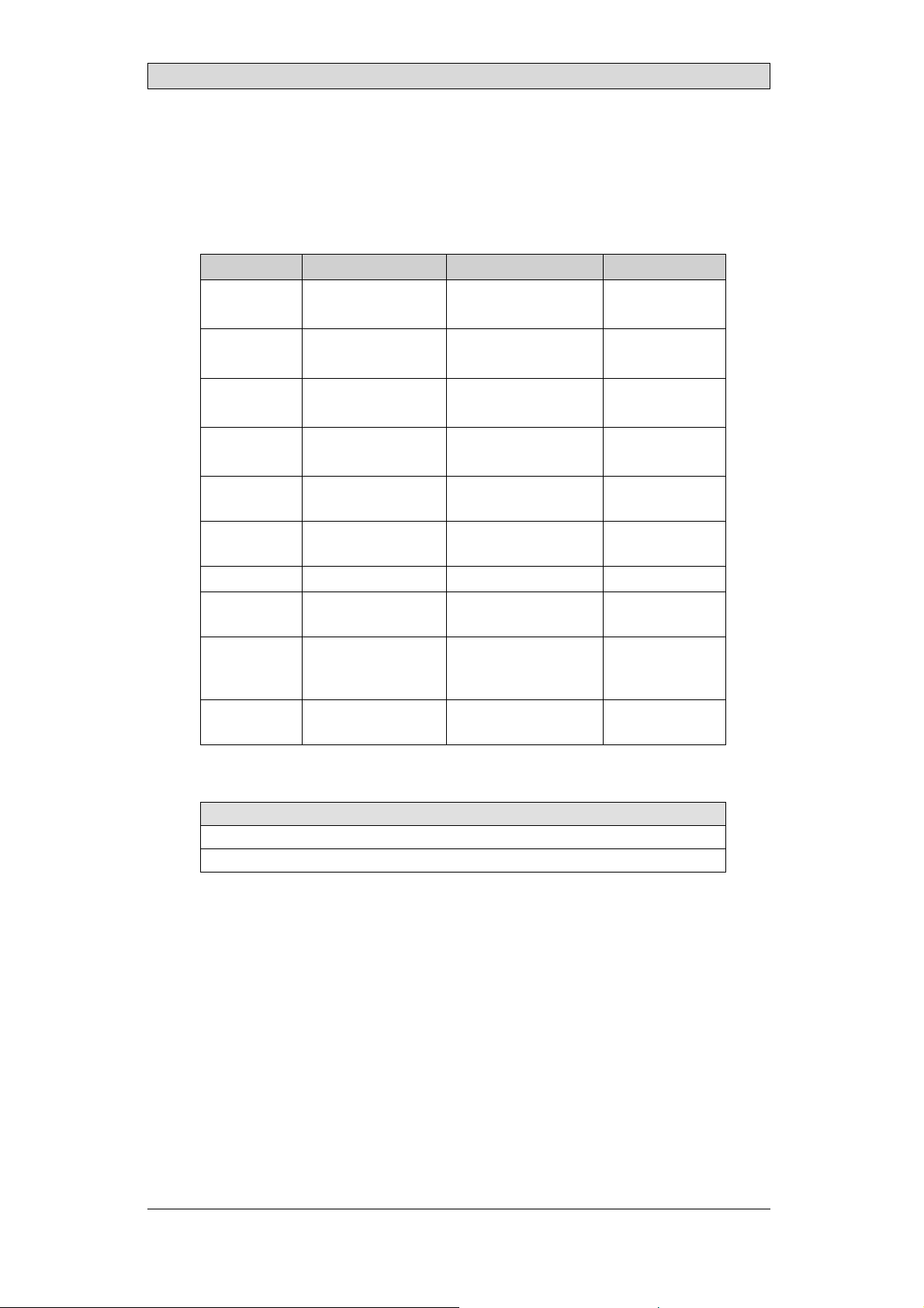
1 Hardware
An RBC module is a built-in part of an EPC C2D Nautic or an MTe monitor.
Supported features depend on the device.
Component Function Description Device support
4 DIP switches Monitor addressing Monitor Address DIP
Switch Settings
3 buttons Poweron/off
Dimming control
Buzzer Buzzer Buzzer In/Out EPC C2D Nautic
Internal USB
interface
COM A
interface
COM B
interface
Buzzer in/out Buzzer control BuzzerIn/Out MTemonitor
Power remote
button
Internal
4–port USB
2.0 hub
DIP switch Serial mode Serial Mode DIP Switch
* In order alter the DIP switches to change the default address of the EPC C2D Nautic,
the housing has to be opened.
USB connection USB Interface EPC C2D Nautic
RS232/RS485 COM A and COM B Pin
RS232/RS485 COM A and COM B Pin
Power on/off f or
external EPC Nautic
USB connection USB Interface MTe monitor
Dimming EPC C2D Nautic
Configuration
Configuration
Remote Power Out MTe monitor
Settings
EPC C2D Nautic*
MTe monitor
MTe monitor
MTe monitor
MTe monitor
MTe monitor
MTe monitor
MTe monitor
Hardware
DIP Switches
Accessing the DIP Switches
Beijer Electronics, MAEN986C
Related information
4
Page 5
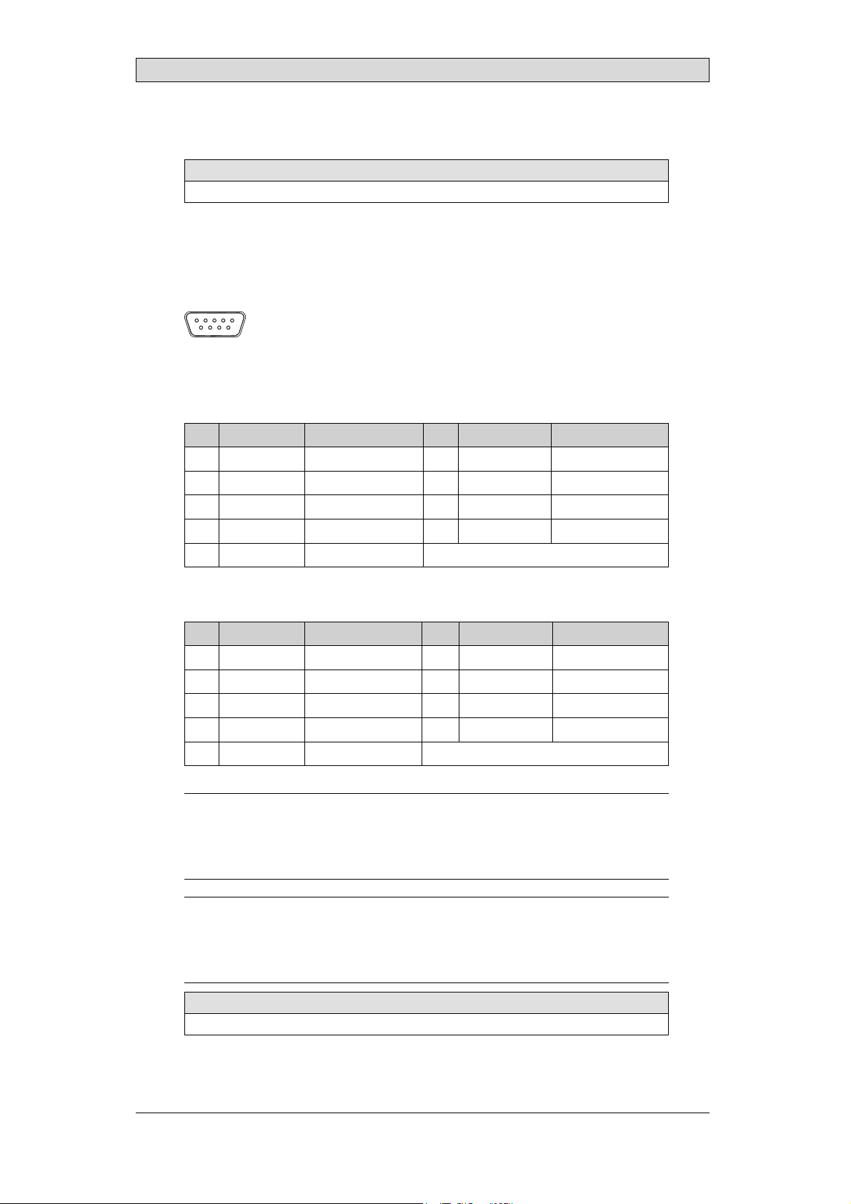
1.1 Interfaces
Related information
MTe Monitor Ports Drawing
1.1.1 COM A and COM B Pin Configuration
The COM A and COM B ports are 9 pin D-SUB female ports.
54321
9876
RS232 Mode
Pin Designation Function Pin Designation Function
1 +5 V +5V 6 – Not connected
2 TxD Transmit data 7 – Not connected
3 RxD Receive data 8 – Do not connect
4 – Not connected 9 GND Ground
5GND Ground
Hardware
RS485 Mode
Pin Designation Function Pin Designation Function
1+5V +5V 6 – Notconnected
2 485+ Differential signal 7 – Not connected
3 – Do not connect 8 485– Differential signal
4 – Do not connect 9 GND Ground
5 GND Ground
Note:
The different pins of COM A and COM B are hard–wired to each other. This means that
using both interfaces at the same time is only allowed in RS485 mode. In RS232 mode
only one interface can be used.
Note:
In RS485 mode the switchingfrom receiving to transmitting and back must be
performed very fast (typical 20 µs). NotallCOM ports or adapters support such a speed.
Make sure that the hardware used is fast enough.
Related information
Serial Mode DIP Switch Settings
Beijer Electronics, MAEN986C
5
Page 6
Hardware
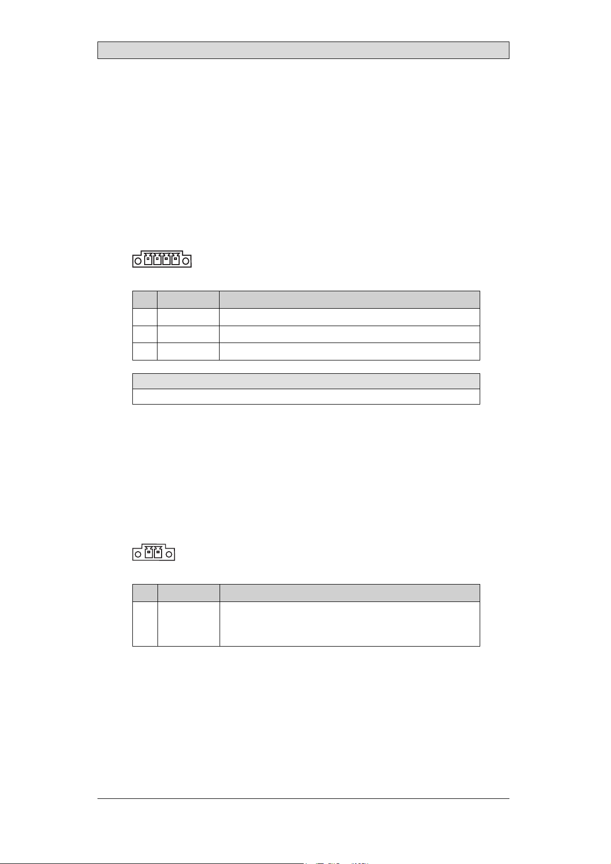
1.1.2 Buzzer In/Out Pin Configuration
There is a buzzer integrated in the front behind the front foil. Itcan be turned on
or off by a SCOM compatible RBC software command.
It can also be activated by the buzzer-in hardware input according to the following
table.
The resulting buzzer-in signal is evaluated by an OR operation on the signals from
software and hardware.
Buzzer-out is a relay contact parallel to the integrated buzzer that can be used to
switch an external signal device.
The buzzer-in and -out can be connected to the 4-pole Phoenix connector:
1 4
Pin Designation Function
1, 2 Out Buzzer-out, NO-contact, max. load 1 A @ 24 V DC
3 In Buzzer-in, +24 V DC
4 In Buzzer-in, ground
Related information
Buzzer In/Out
1.1.3 Power Remote Pin C onfi guration
Remote power out is a relay contact that is closed after the power button on the
front side is pressed for more than one second. Itis opened after the button is
released. Withthe remote power out signal, it is possible to switch an external
Beijer Electronics EPC Nautic on and off. TheEPC hasa corresponding ATX
power remote input. To use this function, connectthe double-pole Phoenix
connector to the corresponding connector on the EPC.
1
2
Pin Designation Function
1, 2 Out RemotePower, NO-contact
To be connected to a Beijer Electronics EPC power remote
input.
Beijer Electronics, MAEN986C
6
Page 7

Hardware
1.1.4 USB Interface
TheUSBinterfaceoftheRBCmodulecannotbeaccesseddirectlybyaplug.
In an EPC, the USB interface is built-in and internally connected to the USB root
hub of the PC. This means that if the PC is running, the USB interface is always
accessible.
In an external MTe monitor,the USB interface is accessible if the monitor is
connected to the PC by a USB cable. Indetail a 4-PortUSB 2.0 hub is accessible to
which the RBC module and other monitor components are connected.
If an MTe XXX E (Ethernet) is connected by an Ethernetcable to a PC, the RBC
is accessible as a USB device too, because a virtual USB connection exists using
the Ethernet hardware.
Beijer Electronics, MAEN986C
7
Page 8
Hardware
1.2 DIP Switches
The DIP switches can be used to adjust the mode of the serial interfaces as well
as the monitor address.
The four DIP switches that areused to set addresses entails setting 16 binary
addresses (0–15) This makes it possible to connect up to 16 monitor for example
via the RS485 interface. It is possible to ignore the DIP switch settings; instead
using software settings for address and serial mode and assigning up to 240
different monitor addresses in 15 different groups.
With the default setting, all DIP switches are OFF, which means that the monitor
is set with address 0 in RS232 mode.
Related information
Using Software Settings Instead of DIP Switches
1.2.1 Accessing theDIP Switches
TheDIPswitchesareplacedontheRBCmodule,thatisabuilt-inpartofanEPC
C2D Nautic or an MTe monitor.
MTe Monitor DIPSwitches
The DIP switches onthe MTe Monitor are located next to the COM ports and are
available from the outside of the device.
EPC C2D Nautic DIP Switches
To access the DIP switches that are located on the RBC module of the EPC C2D
Nautic,the housing has to be opened according to the steps below.
Note:
Inside the EPC there are electronic components which can be destroyed by
electrostatic charges. Therefore cautionary measures have to be taken from the
moment the EPC is opened. These can be found in the guidelines for electrostatic
endangered components (EGB-guidelines).
1.
Disconnect the EPC from the powersupply.
Warning:
Make sure that your electrostatic p ad does not damage the front panel of
the EPC.
2.
Loosen the screws of the left part of the back cover(the partwith the fan) using
a 2.0 mm Allen key.
After removing the screws, the enclosure can be easily opened. Be careful with
the cables connected to the fan.
3.
Locate the DIP switches on the RBC module, positionedat the opposite side
from the communication ports.
Beijer Electronics, MAEN986C
8
Page 9

Hardware
4.
Make the desiredDIP switch settings.
5.
Replace the back cover.
1.2.2 Serial ModeD IP Switch Settings
DIP switch 5 is used to set COM A and COM B in RS232 or RS485 mode.
Mode DIP switch 5
RS485 ON
RS232 (default) OFF
1.2.3 Monitor AddressDIP Switch Settings
DIP switches 1–4 are used to set the monitor addresses.
Address DIP switch 1 DIP switch 2 DIP switch 3 DIP switch 4
0 OFF OFF OFF OFF
1 ON OFF OFF OFF
2 OFF ON OFF OFF
3ONONOFFOFF
4 OFF OFF ON OFF
5 ON OFF ON OFF
6 OFF ON ON OFF
7ONONONOFF
8 OFF OFF OFF ON
9ON OFFOFFON
10 OFF ON OFF ON
11 ON ON OFF ON
12 OFF OFF ON ON
13 ON OFF ON ON
14OFFONONON
15 ON ON ON ON
1.2.4 Example
12345
This example sets the address to 5 and the mode to RS232.
Beijer Electronics, MAEN986C
9
Page 10

Firmware
2Firmware
The internal firmware is responsible for all software tasks running on the RBC
module, especially the SCOM command handling, USB, RS232 and RS485
support and keyboard evaluation.
The firmware is stored in a non-volatile memory in the controller and can be
updatedbyourserviceteamonly.
2.1 Firmware Configuration
The tool RBCFrmConfigurator.exe, a part of the Monitor Control Center, can
be used to change some firmware properties, in order to fit the user’sneeds. All
settingsarestoredinaninternalnon-volatilememory. Thesettingsareonlyread
once at power on or reset. This means that runtime changes are valid after the
next restart.
If an RBC module is connected immediatelyto thePC where the Configurator is
running, the RBC Router must not be running. This is the case if using an RS232,
RS485 or USB connection.
If the RBC module to be configured is connected immediately to another PC,
the RBC Router must be running on that PC. The two PCs have to be connected
by a RS232, RS485 or Ethernet cable.
ThecorrectinterfaceandthecorrectaddressoftheRBCmodulehastobeselected
in everycase. Only if both are correct, the configuration will be successful.
The following properties can be configured:
Note:
The delivered software is for Windows operating systemsonly. Itwas written for
Windows XP and Windows 7.
The software needsto access interfaces like COM ports a n d USB. Therefore the
software needs to be run as administrator otherwise it will not function correctly. If
the user is not logged in as administrator, the Windows tool "runas" can be used. The
disadvantage of "runas" is that administrator and password must be known.
There are commercial tools on the market where these inputscan be set once by the
administrator resulting in that the software thereafter can be run with administrator
privileges by any user.
Firmware property
Using Software Settings Instead of DIP Switches
Remote Control
Default Brightness
Startup Brightness Mode
Keypress Mode
There are some additional properties that can be used by authorized users only.
Related information
RBC Router
Beijer Electronics, MAEN986C
10
Page 11

Firmware
2.1.1 Using SoftwareSettings Instead of
DIP Switches
The DIP switches can be used to adjust the mode of the serial interfaces as well as
the monitor address. Bydefault, DIP switch settings are used.
Alternatively, it is possible to ignore the DIP switch settings; instead using software
settings for address and serial mode. DIPswitches allow addresses from 0.0
(Group.Address)to 0.15, i.e. 16 different addresses, always in group 0. Software
settings allow addresses from 0.0 to 14.15, i.e. 240different addressesin 15
different groups.
Make sure to use every monitor address in a network only one time.
2.1.2 Remote Control
TheRemoteControlfeaturespecifiesifthemonitorshouldbeabletocontrol
the backlight brightness of other monitors (default) or not. Ifremote controlis
enabled, all monitors to be controlled must be reachable. That means that exactly
one monitor can be connected using the RS232 interface or several monitors can
be connected using the RS485 interface. Another possibility is to connect this
monitor to a PC (using RS232, RS485 or USB) where the RBC Router is running.
Depending on the configuration of this RBC Router,it is possible to control a ll
connected monitors.
If only one of the dimmer buttons is pressed, the remote control command is
transmitted whenthe button is released. Ifboth di mmer buttons are pressed, the
command is transmitted after one second, if configured.
Related information
Remote Dimming
Keypress Mode
2.1.3 Default Brightness
TheDefaultBrightnesscanbeusedaskeypressbrightnessorasstartupbrightness
after power on or reset. The range is from 0 (darkest) to 255 (brightest).
Related information
Keypress Mode
Startup Brightness Mode
Beijer Electronics, MAEN986C
11
Page 12

Firmware
2.1.4 Startup BrightnessM ode
The Startup Brightness Mode specifies backlight brightness after poweron or
reset, in one of the following ways:
• darkest (0)
• brightest (255)
• default brightness
• last brightness before power off
By changing the Default Brightness, it is possibleto start the device with any
brightness in the allowed range of 0 to 255.
Related information
Default Brightness
2.1.5 Keypress Mode
The Keypress Mode specifies the behavior of the backlight brightness after both
dimmerbuttonsarepressedatthesametimeforonesecondorlonger,inoneof
the following ways:
• none (no change i n brightness)
• darkest (0)
• brightest (255)
• default brightness
• last SCOM brightness, set by the latest received SCOM brightness command
When last SCOM is specified, the brightness is set to the same value as last received
SCOM brightness command did. It is useful if meanwhile the brightness was
changed to another value by pressingone of the dimmer buttons on the front.
Related information
Default Brightness
Beijer Electronics, MAEN986C
12
Page 13

3Operation
3.1 RBC Driver
The RBC hardware is based on a Microchip Technology Inc. controller
supporting USB. Microchip provides a General Purpose USB Windows driver
which is used t ogether with the RBC module. Thecurrent version is v1.0.0.6 of
January 4th, 2008.
3.1.1 System Requirements
Microchip’s General PurposeUSB Windows driver supports the following
operating systems:
Supported operatingsystems
Windows 2000 Windows Vista
Windows Server 2003 Windows Vista 64
Windows XP Windows 7 (32-bit)
Windows XP 64
Operation
3.1.2 Driver Installation
Thefirsttimeamonitorisconnecte
hardware is automatically detec
The New HardwareWizard leads you through the driver installation in the
following steps:
d to a USB interface on a PC, the new
ted.
Beijer Electronics, MAEN986C
13
Page 14

1.
In the first window select No, not this time, and click Next.
Operation
2.
Select Install from a list or specific location (A
dvanced),andclickNext.
Beijer Electronics, MAEN986C
14
Page 15

3.
Select the path to the driver, and click Next.
Operation
On the MTe/EPC C2D Nautic Driver and Documentati
is located at (CD-ROM):\EPC_C2D_Nautic_PC\M
onitorControlCenter\
rbcdriver_windows.
The installation is now running.
4.
Click Finish.
The hardware can be used now,as displayed in the new message.
on CD, the driver
Beijer Electronics, MAEN986C
15
Page 16

Operation
3.2 SCOM Protocol
The implemented SCOM Protocol is designed for remote controllingof different
devices over different kinds of interfaces. It is based on, and compatible with,
the “SCOM Protocol”(Originally developed by Hatteland). Besides the
standard command set, theimplemented SCOM Protocol includesa rich set
of special purpose com mands for extended remote controlling options. The
manual MAEN993 shows all SCOM commands supported by the RBC series.
The SCOM Protocolis extended with these special features, without affecting
compatibility with other SCOM devices. Some of the major extensions are:
• USB support
• Special purpose command set available with the new SCOM command
“LAU”.
• Extended address field functionality, which enables device grouping, allowing
a total count of 240 devices in a network (15 groups, 16 devices in each
group).
Many examples in different programming languages are available on the
MTe/EPC C2D Nautic Driver andDocumentation CD, showing how to
implement SCOM commands in customer programs. The RBC Samples are also
available in the MonitorControl Center after installation.
3.3 Dimming
The monitor can be dimmed in different ways. The typical way is to use the
dimmer buttons on the front of the monitor.
Button Instruction Description
Press - (brightness down) on the
dimmer button (single step or
automatic repeating after one second)
Press + (brightness up) on the dimmer
button (single ste p or automatic
repeating after one second)
Press + and - simultaneously for more
than one second
The dimmer buttons can be disabled and enabled by a SCOM compatible RBC
software command (POT). All supported SCOM compatible commands are
described in the SCOM Protocol on RBC manual.
TheRBCmoduleofferstheremotedimmingaswell,usingtheserialport,aUSB
port or Ethernet.
Related information
Firmware Configuration
SCOM ProtocolonRBC Manual MAEN993x
Makes the display darker
Makes the display brighter
Tu r n s o n fu l l brightness
quickly (default - this may
be configured)
Beijer Electronics, MAEN986C
16
Page 17

Operation
3.3.1 Remote Dimming
The Remote Dimming feature allows building local networks of connected
monitors where any m onitor can control the backlight brightness of any other
monitor. If the Remote Control feature of a single monitor is not enabled,
this monitor cannot control other monitors, but it can be controlled by other
monitors.
The following examples show some possible types of monitor networks. The PC
showninsomeoftheexamplescanhaveadisplaywithanRBCmoduleaswell.
The built-in monitors have an internal USB connection to the PC and do not
support RS232 or RS485.
Make sure to use every monitor address in a network only one time.
Point-to-Point
Two monitors can control each other, if they are connected via RS232.
Multiple Monitors
More than two monitors can be connected and control each other via an RS485
bus.
Beijer Electronics, MAEN986C
17
Page 18

Operation
USB Network
Several monitors can control each other if they have a USB connection to the same
PC. To enable this feature, the RBC Router must run on the PC, and USB output
must be enabled.
Local Universal Network
Several monitors can control each other if they have any of the supported
connections RS232, RS485 or USB to the same PC. To enable this feature, the
RBC Router must run on the PC, and RS232 output, RS485 output or USB
output must be enabled.
Beijer Electronics, MAEN986C
18
Page 19

Operation
Global Universal Network
Several monitors in different local networkscan control each o ther if they are
connected via Ethernet, RS232 (only two PCs per connection) or RS485. To
enable this feature, the RBC Router must run on every PC, and RS232 output,
RS485 output, USB output and Ethernetinput must be enabled.
Note:
If the brightness is changed at different monitors at almost the same time, every
change creates a command. The last command in the network will finallycontrol the
brightness of all reachable monitors. Withmanycommandswithshorttime-laginthe
network,andifitisconfigured to return answers,mistakes may occur.
3.4 Buzzer In/Out
There is a buzzerintegrated in the front behind the front foil. The buzzer can be
activated by a hardwareinput, or be turned on or off by a SCOM compatible RBC
software command.
The resulting buzzer-in signal is eva
from software and hardware. All s
described in the SCOM Protocol o
turning the buzzer on or off for
luated by an OR operation on the signals
upported SCOM compatible commands are
n RBC manual. The software command allows
a single monitor or for all reachable monitors
(broadcast).
The buzzer-out signal can be influenced only indirectly by setting one of the
buzzer-in signals.
Related information
Buzzer In/Out Pin Configuration
MTe Nautic Installation Manual MAEN983x
SCOM ProtocolonRBC Manual MAEN993x
3.5 Remote Power Out
The remote power out is a pure hardware signal and cannot be influenced by
software.
Beijer Electronics, MAEN986C
19
Page 20

Operation
3.6 Additional Software
Note:
The delivered software is for Windows operating systemsonly. Itwas written for
Windows XP and Windows 7.
The software needsto access interfaces like COM ports a n d USB. Therefore the
software needs to be run as administrator otherwise it will not function correctly. If
the user is not logged in as administrator, the Windows tool "runas" can be used. The
disadvantage of "runas" is that administrator and password must be known.
There are commercial tools on the market where these inputscan be set once by the
administrator resulting in that the software thereafter can be run with administrator
privileges by any user.
3.6.1 RBC Router
The RBC Router is a servicethat handles SCOM commands. It is a part of the
Monitor Control Center. The task of the RBC Router in general is to receive
SCOM commands from input interfaces and transfer them to the output
interfaces. Additionally, the output interfaces are scanned for answers or for new
commands which are transferred to other monitors or interfaces. A typical new
command is the brightness command transmitted from a monitor just controlling
other monitors. The configuration of the input and output interfaces and the
selection of different options can be determined by a configurator. TheRBC
Router can be started and stopped using the Monitor Control Center.
IftheRBCFirmwareConfiguratorisrunning,itdependsonthetypeof
connection to the RBC module if the RBC Router is needed or must not run.
Make sure to use every monitor address in a network only one time.
Related information
RBC Router Configuration
Firmware Configuration
RBC Viewer
3.6.2 RBC Router Configuration
Before starting the RBC Router,it is recommended to make the configuration.
The tool RBCRouterConfigurator.exe, part of the MonitorControl Center, offers
a convenient way for this configuration. ToreduceanyoverheadwhiletheRBC
Router is operating, the configuration should exactly fit the customers needs. The
input interfacestypically specify connections to other PCs or supervising PCs.
The output interfaces typically specify connections to RBC modules,allowing
only enabling of the interfaces in use.
Additional options allow
• returning answers from output to input interfaces
• forwarding (brightness) commands from one output to all output interfaces
• forwarding (brightness) commandsfrom one output to all input interfaces
• searching for non-Beijer Electronics/Lauer devices
• specifying the highest monitor address in use
• specifying the time-out for answers
Beijer Electronics, MAEN986C
20
Page 21

• specifying the time-out for clearing the answer buffer
The RBCRouterConfigurator must be called on the same PC wherethe RBC
Router is running. Changes made by the RBCRouterConfigurator will be valid
only after a restart of the RBC Router.
Operation
Beijer Electronics, MAEN986C
21
Page 22

Operation
3.6.3 RBC Viewer
The tool RBCViewer.exe, part of the MonitorControl C enter, offers a convenient
way to show all monitors connected to a PC. All reachable monitors are shown,
independent of hardware connection(USB, RS232, RS485 or Ethernet). The
(series) name, the address and the type of hardware connection is shown for each
connected monitor.
This works only, if a well-configured RBC Router is running.
Related information
RBC Router
Beijer Electronics, MAEN986C
22
Page 23

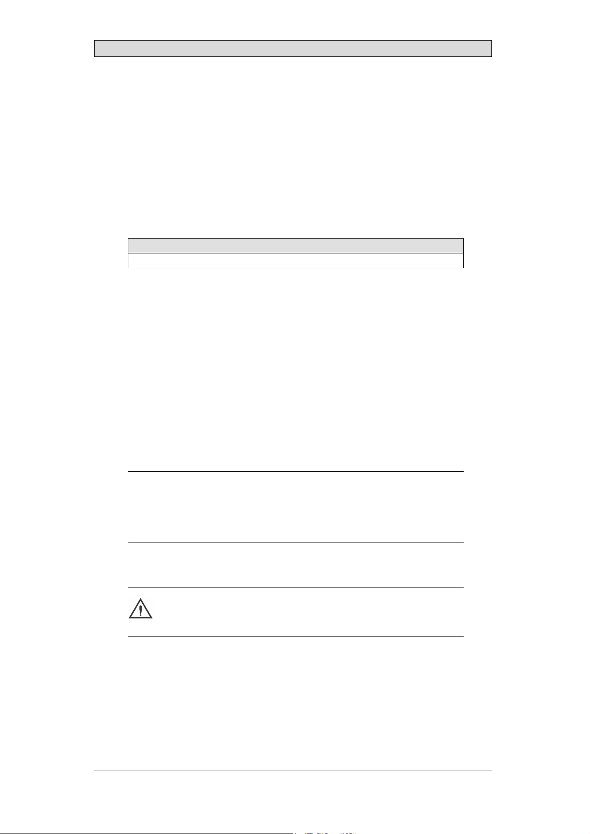
MTe Monitor Ports D rawing
4 MTe Monitor Ports Drawing
DIP switchesPower remote
Buzzer in/out COM A COM B
ON
1
4
1
2
51
OFF
Beijer Electronics, MAEN986C
23
Page 24

Troubleshooting
5Troubleshooting
If the monitor detects an e rror, it beeps twiceatstartupandsetsthefactorydefault
settings. Any customer settings will be overwritten, and need to be configured
again.
If the delivered software does not function correctly, please consider that the
software needs to be r un as administrator.
Beijer Electronics, MAEN986C
24
Page 25

Head office
Beijer Electronics AB
Box 426
20124Malmö,Sweden
www.beijerelectronics.com / +46 40 358600
 Loading...