

Beijer Electronics QTERM-G70, QTERM-G75, QTERM-G56, QTERM-G58, QTERM-G55 Hardware Manual
...Page 1

QLARITY®-BASED TERMINAL
HARDWARE MANUAL
M01-004-00 Rev 06
BEIJER ELECTRONICS
1865 West 2100 South
Salt Lake City, Utah 84119
USA
Phone 801-466-8770
Fax 801-466-8792
Email info@BeijerInc.com
Web http://www.BeijerInc.com
Page 2

Copyright © 2013 Beijer Electronics. Printed in the USA. All rights reserved. No part of this publication may be reproduced, in any form or by any means without prior written permission from Beijer Electronics.
Qlarity and QTERM are registered trademarks of Beijer Electronics.
Microsoft, Windows, Windows NT, Windows 2000, Windows XP, Windows Vista, Windows 7, ActiveSync, and their respective logos are registered trademarks
of Microsoft Corporation in the United States and other countries.
All other brand and product names used in this manual are trademarks or registered trademarks of their respective companies.
Manual updated 29 July 2013.
Page 3

FCC Compliance Statement
This device complies with part 15 of the FCC Rules. Operation is subject to the following two conditions: (1) This device may
not cause harmful interference, and (2) this device must accept any interference received, including interference that may cause
undesired operation.
This equipment has been tested and found to comply with the limits for a Class A digital device, pursuant to part 15 of the FCC
Rules. These limits are designed to provide reasonable protection against harmful interference when the equipment is operated in
a commercial environment. This equipment generates, uses, and can radiate radio frequency energy and, if not installed and used
in accordance with the instruction manual, may cause harmful interference to radio communications. Operation of this equipment
in a residential area is likely to cause harmful interference, in which case the user will be required to correct the interference at his
own expense. Any modification to this device (including any changes to the recommended antenna configuration) that are not
expressly approved by Beijer Electronics could void the user’s authority to operate this device.
Additionally, these devices may contain the following FCC module-certified components depending on product configuration:
MQ4WUG2K7C (QTERM-G58) or MXFC910226 (QTERM-G55).
Page 4

Page 5

CONTENTS
CHAPTER 1. QTERM-G70 TERMINAL . . . . . . . . . . . . . . . . . . . . . . . . . . . . . . . . . . . . . . . . .1
1.1 Product Description . . . . . . . . . . . . . . . . . . . . . . . . . . . . . . . . . . . . . . . . . . . . . . . . . . .1
1.1.1 Specifications . . . . . . . . . . . . . . . . . . . . . . . . . . . . . . . . . . . . . . . . . . . . . . . . . . .2
1.2 Supported Interfaces. . . . . . . . . . . . . . . . . . . . . . . . . . . . . . . . . . . . . . . . . . . . . . . . . . .4
1.2.1 Serial Ports . . . . . . . . . . . . . . . . . . . . . . . . . . . . . . . . . . . . . . . . . . . . . . . . . . . . .4
1.2.2 Optional Ethernet Port . . . . . . . . . . . . . . . . . . . . . . . . . . . . . . . . . . . . . . . . . . . .5
1.2.3 Optional PS/2 Keyboard Interface . . . . . . . . . . . . . . . . . . . . . . . . . . . . . . . . . . .5
1.2.4 Optional 5 Volt Power Supply on Secondary Serial Port. . . . . . . . . . . . . . . . . .5
1.2.5 Optional Dual and Quad EIA-232 Serial Port Card . . . . . . . . . . . . . . . . . . . . . .6
1.2.6 Optional Power-over-Ethernet Module . . . . . . . . . . . . . . . . . . . . . . . . . . . . . . .6
1.2.6.1 Power Requirements . . . . . . . . . . . . . . . . . . . . . . . . . . . . . . . . . . . . . . . . . .6
1.2.6.2 Pinouts . . . . . . . . . . . . . . . . . . . . . . . . . . . . . . . . . . . . . . . . . . . . . . . . . . . . .7
1.3 Terminal Components . . . . . . . . . . . . . . . . . . . . . . . . . . . . . . . . . . . . . . . . . . . . . . . . .7
1.3.1 Touch Screen . . . . . . . . . . . . . . . . . . . . . . . . . . . . . . . . . . . . . . . . . . . . . . . . . . .7
1.3.2 Keyboard. . . . . . . . . . . . . . . . . . . . . . . . . . . . . . . . . . . . . . . . . . . . . . . . . . . . . . .8
1.3.3 Keypad . . . . . . . . . . . . . . . . . . . . . . . . . . . . . . . . . . . . . . . . . . . . . . . . . . . . . . . .8
1.3.4 Speaker . . . . . . . . . . . . . . . . . . . . . . . . . . . . . . . . . . . . . . . . . . . . . . . . . . . . . . . .9
1.3.5 Real-Time Clock. . . . . . . . . . . . . . . . . . . . . . . . . . . . . . . . . . . . . . . . . . . . . . . . .9
1.3.6 System Memory . . . . . . . . . . . . . . . . . . . . . . . . . . . . . . . . . . . . . . . . . . . . . . . . .9
1.3.7 Watchdog Timer. . . . . . . . . . . . . . . . . . . . . . . . . . . . . . . . . . . . . . . . . . . . . . . .10
1.4 Installing to NEMA-4. . . . . . . . . . . . . . . . . . . . . . . . . . . . . . . . . . . . . . . . . . . . . . . . .10
1.4.1 Cutout for Panel Mount Configuration . . . . . . . . . . . . . . . . . . . . . . . . . . . . . . .10
1.4.2 Installing the Panel Mount Terminal . . . . . . . . . . . . . . . . . . . . . . . . . . . . . . . .11
1.4.3 Cutout for Drywall Mount Configuration. . . . . . . . . . . . . . . . . . . . . . . . . . . . .13
1.4.4 Installing the Drywall Mount Terminal . . . . . . . . . . . . . . . . . . . . . . . . . . . . . .13
1.4.4.1 Removing the Drywall Mount Terminal . . . . . . . . . . . . . . . . . . . . . . . . . .14
1.4.5 Applying Power . . . . . . . . . . . . . . . . . . . . . . . . . . . . . . . . . . . . . . . . . . . . . . . .14
1.5 Powering On the Terminal for the First Time . . . . . . . . . . . . . . . . . . . . . . . . . . . . . .15
HAPTER 2. QTERM-G75 TERMINAL . . . . . . . . . . . . . . . . . . . . . . . . . . . . . . . . . . . . . . . .17
C
2.1 Product Description . . . . . . . . . . . . . . . . . . . . . . . . . . . . . . . . . . . . . . . . . . . . . . . . . .17
2.1.1 Specifications . . . . . . . . . . . . . . . . . . . . . . . . . . . . . . . . . . . . . . . . . . . . . . . . . .18
2.2 Supported Interfaces. . . . . . . . . . . . . . . . . . . . . . . . . . . . . . . . . . . . . . . . . . . . . . . . . .20
2.2.1 Serial Ports . . . . . . . . . . . . . . . . . . . . . . . . . . . . . . . . . . . . . . . . . . . . . . . . . . . .20
2.2.2 Optional Ethernet Port . . . . . . . . . . . . . . . . . . . . . . . . . . . . . . . . . . . . . . . . . . .21
2.2.3 Optional PS/2 Keyboard Interface . . . . . . . . . . . . . . . . . . . . . . . . . . . . . . . . . .21
2.2.4 Optional 5 Volt Power Supply on Secondary Serial Port. . . . . . . . . . . . . . . . .21
2.2.5 Optional Dual and Quad EIA-232 Serial Port Card . . . . . . . . . . . . . . . . . . . . .22
2.2.6 Optional Power-over-Ethernet Module . . . . . . . . . . . . . . . . . . . . . . . . . . . . . .22
2.3 Terminal Components . . . . . . . . . . . . . . . . . . . . . . . . . . . . . . . . . . . . . . . . . . . . . . . .22
2.3.1 Touch Screen . . . . . . . . . . . . . . . . . . . . . . . . . . . . . . . . . . . . . . . . . . . . . . . . . .22
2.3.2 Keyboard. . . . . . . . . . . . . . . . . . . . . . . . . . . . . . . . . . . . . . . . . . . . . . . . . . . . . .23
2.3.3 Keypad . . . . . . . . . . . . . . . . . . . . . . . . . . . . . . . . . . . . . . . . . . . . . . . . . . . . . . .23
2.3.4 Speaker . . . . . . . . . . . . . . . . . . . . . . . . . . . . . . . . . . . . . . . . . . . . . . . . . . . . . . .24
Qlarity-Based Terminal Hardware i
Page 6

Contents
2.3.5 Real-Time Clock. . . . . . . . . . . . . . . . . . . . . . . . . . . . . . . . . . . . . . . . . . . . . . . .25
2.3.6 System Memory . . . . . . . . . . . . . . . . . . . . . . . . . . . . . . . . . . . . . . . . . . . . . . . .25
2.3.7 Watchdog Timer. . . . . . . . . . . . . . . . . . . . . . . . . . . . . . . . . . . . . . . . . . . . . . . .25
2.4 Installing to NEMA-4 Specifications. . . . . . . . . . . . . . . . . . . . . . . . . . . . . . . . . . . . .25
2.4.1 Cutting Out the Panel . . . . . . . . . . . . . . . . . . . . . . . . . . . . . . . . . . . . . . . . . . . .26
2.4.2 Installing the Terminal . . . . . . . . . . . . . . . . . . . . . . . . . . . . . . . . . . . . . . . . . . .27
2.4.3 Applying Power . . . . . . . . . . . . . . . . . . . . . . . . . . . . . . . . . . . . . . . . . . . . . . . .28
2.4.4 Powering On the Terminal for the First Time . . . . . . . . . . . . . . . . . . . . . . . . .29
HAPTER 3. QTERM-G55 TERMINAL . . . . . . . . . . . . . . . . . . . . . . . . . . . . . . . . . . . . . . . .31
C
3.1 Product Description . . . . . . . . . . . . . . . . . . . . . . . . . . . . . . . . . . . . . . . . . . . . . . . . . .31
3.1.1 Specifications . . . . . . . . . . . . . . . . . . . . . . . . . . . . . . . . . . . . . . . . . . . . . . . . . .32
3.2 Supported Interfaces. . . . . . . . . . . . . . . . . . . . . . . . . . . . . . . . . . . . . . . . . . . . . . . . . . 34
3.2.1 Handheld Connector Interface . . . . . . . . . . . . . . . . . . . . . . . . . . . . . . . . . . . . .34
3.2.1.1 Power Interface . . . . . . . . . . . . . . . . . . . . . . . . . . . . . . . . . . . . . . . . . . . . .35
3.2.1.2 Primary Serial Interface. . . . . . . . . . . . . . . . . . . . . . . . . . . . . . . . . . . . . . .35
3.2.1.3 Secondary Serial Interface or Network Interface . . . . . . . . . . . . . . . . . . .35
3.2.1.4 E-stop Option. . . . . . . . . . . . . . . . . . . . . . . . . . . . . . . . . . . . . . . . . . . . . . .35
3.2.1.4.1 Power Interface with E-stop Option . . . . . . . . . . . . . . . . . . . . . . . . . .36
3.2.1.4.2 Serial or Network Interface with E-stop Option. . . . . . . . . . . . . . . . .36
3.2.1.4.3 E-stop Switch Interface. . . . . . . . . . . . . . . . . . . . . . . . . . . . . . . . . . . .36
3.2.1.5 Accessory Cable Wire Color Code . . . . . . . . . . . . . . . . . . . . . . . . . . . . . .36
3.2.1.6 Integral Cable. . . . . . . . . . . . . . . . . . . . . . . . . . . . . . . . . . . . . . . . . . . . . . .37
3.2.1.6.1 Power Interface with Integral Cable. . . . . . . . . . . . . . . . . . . . . . . . . .38
3.2.1.6.2 Primary Serial Interface with Integral Cable . . . . . . . . . . . . . . . . . . .38
3.2.1.6.3 Secondary Serial Interface or Network Interface with Integral Cable38
3.2.1.7 E-stop Option with Integral Cable. . . . . . . . . . . . . . . . . . . . . . . . . . . . . . .38
3.2.1.7.1 Power Interface with E-stop Option and Integral Cable. . . . . . . . . . .39
3.2.1.7.2 Serial or Network Interface with E-stop Option and Integral Cable .39
3.2.1.7.3 E-stop Switch Interface with Integral Cable. . . . . . . . . . . . . . . . . . . .39
3.2.1.8 Integral Cable Wire Color Code . . . . . . . . . . . . . . . . . . . . . . . . . . . . . . . .39
3.2.2 Panel-mount Connector Interface. . . . . . . . . . . . . . . . . . . . . . . . . . . . . . . . . . .40
3.2.2.1 Optional Ethernet Port (Panel-mount). . . . . . . . . . . . . . . . . . . . . . . . . . . .41
3.2.3 Optional Power-over-Ethernet Module . . . . . . . . . . . . . . . . . . . . . . . . . . . . . .41
3.2.3.1 Power Requirements . . . . . . . . . . . . . . . . . . . . . . . . . . . . . . . . . . . . . . . . .42
3.2.3.2 Pinouts (Panel-mount). . . . . . . . . . . . . . . . . . . . . . . . . . . . . . . . . . . . . . . .42
3.3 Terminal Components . . . . . . . . . . . . . . . . . . . . . . . . . . . . . . . . . . . . . . . . . . . . . . . .43
3.3.1 Display . . . . . . . . . . . . . . . . . . . . . . . . . . . . . . . . . . . . . . . . . . . . . . . . . . . . . . .43
3.3.2 Keypad . . . . . . . . . . . . . . . . . . . . . . . . . . . . . . . . . . . . . . . . . . . . . . . . . . . . . . .44
3.3.3 Speaker . . . . . . . . . . . . . . . . . . . . . . . . . . . . . . . . . . . . . . . . . . . . . . . . . . . . . . .44
3.3.4 Real-Time Clock. . . . . . . . . . . . . . . . . . . . . . . . . . . . . . . . . . . . . . . . . . . . . . . .45
3.3.5 System Memory . . . . . . . . . . . . . . . . . . . . . . . . . . . . . . . . . . . . . . . . . . . . . . . .45
3.4 Installing to NEMA-4 Specifications. . . . . . . . . . . . . . . . . . . . . . . . . . . . . . . . . . . . .45
3.4.1 Cutout for Panel Mount Configuration. . . . . . . . . . . . . . . . . . . . . . . . . . . . . . .46
3.4.2 Installing the Panel Mount Terminal . . . . . . . . . . . . . . . . . . . . . . . . . . . . . . . .46
3.4.3 Applying Power . . . . . . . . . . . . . . . . . . . . . . . . . . . . . . . . . . . . . . . . . . . . . . . .47
3.4.4 Powering On the Terminal for the First Time . . . . . . . . . . . . . . . . . . . . . . . . .47
ii
Qlarity-Based Terminal Hardware
Page 7

Contents
CHAPTER 4. QTERM-G56 TERMINAL . . . . . . . . . . . . . . . . . . . . . . . . . . . . . . . . . . . . . . . .49
4.1 Product Description . . . . . . . . . . . . . . . . . . . . . . . . . . . . . . . . . . . . . . . . . . . . . . . . . .49
4.1.1 Specifications . . . . . . . . . . . . . . . . . . . . . . . . . . . . . . . . . . . . . . . . . . . . . . . . . .50
4.2 Supported Interfaces. . . . . . . . . . . . . . . . . . . . . . . . . . . . . . . . . . . . . . . . . . . . . . . . . .52
4.2.1 Connector Interface . . . . . . . . . . . . . . . . . . . . . . . . . . . . . . . . . . . . . . . . . . . . .52
4.2.1.1 Power and USB Device Interfaces. . . . . . . . . . . . . . . . . . . . . . . . . . . . . . .53
4.2.1.2 Serial Multiprotocol Port Interface . . . . . . . . . . . . . . . . . . . . . . . . . . . . . .53
4.2.1.3 Additional Serial Interface (without Ethernet option). . . . . . . . . . . . . . . .53
4.2.1.4 Network Interface (with Ethernet option) . . . . . . . . . . . . . . . . . . . . . . . . .53
4.2.1.5 Accessory Cable Wire Color Code and Demo Cable Pinout. . . . . . . . . . .54
4.2.2 Integral Cable . . . . . . . . . . . . . . . . . . . . . . . . . . . . . . . . . . . . . . . . . . . . . . . . . .54
4.2.2.1 Power and USB Device Interfaces with Integral Cable. . . . . . . . . . . . . . .55
4.2.2.2 Serial Interface with Integral Cable. . . . . . . . . . . . . . . . . . . . . . . . . . . . . .55
4.2.2.3 Additional Serial Interface with Integral Cable (without Ethernet option)55
4.2.2.4 Network Interface with Integral Cable (with Ethernet option) . . . . . . . . .56
4.2.2.5 E-stop Option with Integral Cable. . . . . . . . . . . . . . . . . . . . . . . . . . . . . . .56
4.2.2.6 Power and USB Device Interfaces with E-stop Option and Integral Cable56
4.2.2.7 Serial Interface with E-Stop Option and Integral Cable (without Ethernet op-
tion) . . . . . . . . . . . . . . . . . . . . . . . . . . . . . . . . . . . . . . . . . . . . . . . . . . . . . .56
4.2.2.8 Additional Serial Interface with E-Stop Option and Integral Cable (without
Ethernet option). . . . . . . . . . . . . . . . . . . . . . . . . . . . . . . . . . . . . . . . . . . . .57
4.2.2.9 Network Interface with E-Stop Option and Integral Cable (with Ethernet op-
tion) . . . . . . . . . . . . . . . . . . . . . . . . . . . . . . . . . . . . . . . . . . . . . . . . . . . . . .57
4.2.2.10 Serial Interface with E-stop Option and Integral Cable (with Ethernet op-
tion) . . . . . . . . . . . . . . . . . . . . . . . . . . . . . . . . . . . . . . . . . . . . . . . . . . . . . .57
4.2.2.11 E-stop Switch Interface with Integral Cable . . . . . . . . . . . . . . . . . . . . . .57
4.2.2.12 Integral Cable Wire Color Code . . . . . . . . . . . . . . . . . . . . . . . . . . . . . . .58
4.3 Terminal Components . . . . . . . . . . . . . . . . . . . . . . . . . . . . . . . . . . . . . . . . . . . . . . . .58
4.3.1 Display . . . . . . . . . . . . . . . . . . . . . . . . . . . . . . . . . . . . . . . . . . . . . . . . . . . . . . .58
4.3.2 Touch Screen . . . . . . . . . . . . . . . . . . . . . . . . . . . . . . . . . . . . . . . . . . . . . . . . . .59
4.3.3 Keypad . . . . . . . . . . . . . . . . . . . . . . . . . . . . . . . . . . . . . . . . . . . . . . . . . . . . . . .59
4.3.4 Speaker . . . . . . . . . . . . . . . . . . . . . . . . . . . . . . . . . . . . . . . . . . . . . . . . . . . . . . .59
4.3.5 Real-Time Clock. . . . . . . . . . . . . . . . . . . . . . . . . . . . . . . . . . . . . . . . . . . . . . . .60
4.3.6 System Memory . . . . . . . . . . . . . . . . . . . . . . . . . . . . . . . . . . . . . . . . . . . . . . . .60
4.3.7 Applying Power . . . . . . . . . . . . . . . . . . . . . . . . . . . . . . . . . . . . . . . . . . . . . . . .61
4.4 Powering On the Terminal for the First Time . . . . . . . . . . . . . . . . . . . . . . . . . . . . . .61
4.4.1 Accessing The Internal Mass Storage Via USB. . . . . . . . . . . . . . . . . . . . . . . .62
HAPTER 5. QTERM-G58 TERMINAL . . . . . . . . . . . . . . . . . . . . . . . . . . . . . . . . . . . . . . . .63
C
5.1 Product Description . . . . . . . . . . . . . . . . . . . . . . . . . . . . . . . . . . . . . . . . . . . . . . . . . .63
5.1.1 Specifications . . . . . . . . . . . . . . . . . . . . . . . . . . . . . . . . . . . . . . . . . . . . . . . . . .64
5.2 Supported Interfaces. . . . . . . . . . . . . . . . . . . . . . . . . . . . . . . . . . . . . . . . . . . . . . . . . .66
5.2.1 Connector Interface . . . . . . . . . . . . . . . . . . . . . . . . . . . . . . . . . . . . . . . . . . . . .66
5.2.1.1 Power and USB Device Interfaces. . . . . . . . . . . . . . . . . . . . . . . . . . . . . . .67
5.2.1.2 Serial Multiprotocol Port Interface . . . . . . . . . . . . . . . . . . . . . . . . . . . . . .67
5.2.1.3 Accessory Cable Wire Color Code and Demo Cable Pinout. . . . . . . . . . .67
5.3 Terminal Components . . . . . . . . . . . . . . . . . . . . . . . . . . . . . . . . . . . . . . . . . . . . . . . .68
Qlarity-Based Terminal Hardware iii
Page 8

Contents
5.3.1 Display . . . . . . . . . . . . . . . . . . . . . . . . . . . . . . . . . . . . . . . . . . . . . . . . . . . . . . .68
5.3.2 Touch Screen . . . . . . . . . . . . . . . . . . . . . . . . . . . . . . . . . . . . . . . . . . . . . . . . . .68
5.3.3 Keypad . . . . . . . . . . . . . . . . . . . . . . . . . . . . . . . . . . . . . . . . . . . . . . . . . . . . . . .69
5.3.4 Speaker . . . . . . . . . . . . . . . . . . . . . . . . . . . . . . . . . . . . . . . . . . . . . . . . . . . . . . .69
5.3.5 Real-Time Clock. . . . . . . . . . . . . . . . . . . . . . . . . . . . . . . . . . . . . . . . . . . . . . . .69
5.3.6 System Memory . . . . . . . . . . . . . . . . . . . . . . . . . . . . . . . . . . . . . . . . . . . . . . . .70
5.3.7 Applying Power . . . . . . . . . . . . . . . . . . . . . . . . . . . . . . . . . . . . . . . . . . . . . . . .70
5.4 Powering On the Terminal for the First Time . . . . . . . . . . . . . . . . . . . . . . . . . . . . . .71
5.4.1 Powering and Charging the Battery Powered QTERM-G58 . . . . . . . . . . . . . .71
5.4.2 Accessing The Internal Mass Storage Via USB. . . . . . . . . . . . . . . . . . . . . . . .72
HAPTER 6. QTERM-Z60 TERMINAL. . . . . . . . . . . . . . . . . . . . . . . . . . . . . . . . . . . . . . . . .73
C
6.1 Product Description . . . . . . . . . . . . . . . . . . . . . . . . . . . . . . . . . . . . . . . . . . . . . . . . . .73
6.1.1 Specifications . . . . . . . . . . . . . . . . . . . . . . . . . . . . . . . . . . . . . . . . . . . . . . . . . .73
6.2 Supported Interfaces. . . . . . . . . . . . . . . . . . . . . . . . . . . . . . . . . . . . . . . . . . . . . . . . . . 75
6.2.1 Serial Ports . . . . . . . . . . . . . . . . . . . . . . . . . . . . . . . . . . . . . . . . . . . . . . . . . . . .75
6.2.2 Five Volt Power Supply Output . . . . . . . . . . . . . . . . . . . . . . . . . . . . . . . . . . . .76
6.2.3 External Reset Input . . . . . . . . . . . . . . . . . . . . . . . . . . . . . . . . . . . . . . . . . . . . .77
6.3 Terminal Components . . . . . . . . . . . . . . . . . . . . . . . . . . . . . . . . . . . . . . . . . . . . . . . .77
6.3.1 Touch Screen . . . . . . . . . . . . . . . . . . . . . . . . . . . . . . . . . . . . . . . . . . . . . . . . . .77
6.3.2 Speaker . . . . . . . . . . . . . . . . . . . . . . . . . . . . . . . . . . . . . . . . . . . . . . . . . . . . . . .77
6.3.3 System Memory . . . . . . . . . . . . . . . . . . . . . . . . . . . . . . . . . . . . . . . . . . . . . . . .78
6.4 Installing to NEMA-4 Specifications. . . . . . . . . . . . . . . . . . . . . . . . . . . . . . . . . . . . .78
6.4.1 Cutting Out the Panel . . . . . . . . . . . . . . . . . . . . . . . . . . . . . . . . . . . . . . . . . . . .78
6.4.2 Installing the Terminal . . . . . . . . . . . . . . . . . . . . . . . . . . . . . . . . . . . . . . . . . . .79
6.4.3 Applying Power . . . . . . . . . . . . . . . . . . . . . . . . . . . . . . . . . . . . . . . . . . . . . . . .80
6.4.4 Powering On the Terminal for the First Time . . . . . . . . . . . . . . . . . . . . . . . . .81
iv
HAPTER 7. QTERM-G72 TERMINAL . . . . . . . . . . . . . . . . . . . . . . . . . . . . . . . . . . . . . . . .83
C
7.1 Product Description . . . . . . . . . . . . . . . . . . . . . . . . . . . . . . . . . . . . . . . . . . . . . . . . . .83
7.1.1 Specifications . . . . . . . . . . . . . . . . . . . . . . . . . . . . . . . . . . . . . . . . . . . . . . . . . .84
7.2 Supported Interfaces. . . . . . . . . . . . . . . . . . . . . . . . . . . . . . . . . . . . . . . . . . . . . . . . . . 87
7.2.1 Primary Serial Port (Multiprotocol Port Interface). . . . . . . . . . . . . . . . . . . . . .87
7.2.2 Secondary Serial Port . . . . . . . . . . . . . . . . . . . . . . . . . . . . . . . . . . . . . . . . . . . .88
7.2.3 Ethernet Port. . . . . . . . . . . . . . . . . . . . . . . . . . . . . . . . . . . . . . . . . . . . . . . . . . .89
7.2.4 USB 2.0 Port. . . . . . . . . . . . . . . . . . . . . . . . . . . . . . . . . . . . . . . . . . . . . . . . . . .90
7.2.5 Terminal Strip for Power Input. . . . . . . . . . . . . . . . . . . . . . . . . . . . . . . . . . . . .90
7.3 Terminal Components . . . . . . . . . . . . . . . . . . . . . . . . . . . . . . . . . . . . . . . . . . . . . . . .91
7.3.1 Touch Screen . . . . . . . . . . . . . . . . . . . . . . . . . . . . . . . . . . . . . . . . . . . . . . . . . .91
7.3.2 Speaker . . . . . . . . . . . . . . . . . . . . . . . . . . . . . . . . . . . . . . . . . . . . . . . . . . . . . . .91
7.3.3 Real-Time Clock. . . . . . . . . . . . . . . . . . . . . . . . . . . . . . . . . . . . . . . . . . . . . . . .91
7.3.4 System Memory . . . . . . . . . . . . . . . . . . . . . . . . . . . . . . . . . . . . . . . . . . . . . . . .91
7.3.5 Watchdog Timer. . . . . . . . . . . . . . . . . . . . . . . . . . . . . . . . . . . . . . . . . . . . . . . .92
7.4 Installing to NEMA-4X Specifications . . . . . . . . . . . . . . . . . . . . . . . . . . . . . . . . . . .92
7.4.1 Cutting Out for Panel Mount . . . . . . . . . . . . . . . . . . . . . . . . . . . . . . . . . . . . . .93
7.4.2 Installing the Terminal . . . . . . . . . . . . . . . . . . . . . . . . . . . . . . . . . . . . . . . . . . .93
7.4.3 Applying Power . . . . . . . . . . . . . . . . . . . . . . . . . . . . . . . . . . . . . . . . . . . . . . . .95
Qlarity-Based Terminal Hardware
Page 9

Contents
7.4.4 Powering On the Terminal for the First Time . . . . . . . . . . . . . . . . . . . . . . . . .96
C
HAPTER 8. POWER ON SETUP . . . . . . . . . . . . . . . . . . . . . . . . . . . . . . . . . . . . . . . . . . . . . .97
8.1 Using a Touch Screen . . . . . . . . . . . . . . . . . . . . . . . . . . . . . . . . . . . . . . . . . . . . . . . .97
8.2 Using a Keypad . . . . . . . . . . . . . . . . . . . . . . . . . . . . . . . . . . . . . . . . . . . . . . . . . . . .100
8.3 Using a Keyboard. . . . . . . . . . . . . . . . . . . . . . . . . . . . . . . . . . . . . . . . . . . . . . . . . . .101
8.4 Power On Setup Functions. . . . . . . . . . . . . . . . . . . . . . . . . . . . . . . . . . . . . . . . . . . .102
8.4.1 Flash Memory. . . . . . . . . . . . . . . . . . . . . . . . . . . . . . . . . . . . . . . . . . . . . . . . .103
8.4.1.1 App Mode . . . . . . . . . . . . . . . . . . . . . . . . . . . . . . . . . . . . . . . . . . . . . . . .103
8.4.1.2 Erase FFS. . . . . . . . . . . . . . . . . . . . . . . . . . . . . . . . . . . . . . . . . . . . . . . . .105
8.4.2 Display . . . . . . . . . . . . . . . . . . . . . . . . . . . . . . . . . . . . . . . . . . . . . . . . . . . . . .105
8.4.2.1 Contrast . . . . . . . . . . . . . . . . . . . . . . . . . . . . . . . . . . . . . . . . . . . . . . . . . .105
8.4.2.2 Backlight . . . . . . . . . . . . . . . . . . . . . . . . . . . . . . . . . . . . . . . . . . . . . . . . .105
8.4.2.3 Orient. . . . . . . . . . . . . . . . . . . . . . . . . . . . . . . . . . . . . . . . . . . . . . . . . . . .106
8.4.2.4 Touch. . . . . . . . . . . . . . . . . . . . . . . . . . . . . . . . . . . . . . . . . . . . . . . . . . . .106
8.4.2.5 DCache. . . . . . . . . . . . . . . . . . . . . . . . . . . . . . . . . . . . . . . . . . . . . . . . . . .106
8.4.3 Calibration . . . . . . . . . . . . . . . . . . . . . . . . . . . . . . . . . . . . . . . . . . . . . . . . . . .107
8.4.3.1 Temp . . . . . . . . . . . . . . . . . . . . . . . . . . . . . . . . . . . . . . . . . . . . . . . . . . . .107
8.4.3.2 Date . . . . . . . . . . . . . . . . . . . . . . . . . . . . . . . . . . . . . . . . . . . . . . . . . . . . .107
8.4.3.3 Time. . . . . . . . . . . . . . . . . . . . . . . . . . . . . . . . . . . . . . . . . . . . . . . . . . . . .108
8.4.3.4 Touchscreen. . . . . . . . . . . . . . . . . . . . . . . . . . . . . . . . . . . . . . . . . . . . . . .108
8.4.4 Network . . . . . . . . . . . . . . . . . . . . . . . . . . . . . . . . . . . . . . . . . . . . . . . . . . . . .109
8.4.5 Wireless . . . . . . . . . . . . . . . . . . . . . . . . . . . . . . . . . . . . . . . . . . . . . . . . . . . . .110
8.4.6 Security. . . . . . . . . . . . . . . . . . . . . . . . . . . . . . . . . . . . . . . . . . . . . . . . . . . . . .110
8.4.7 COM1 and Any Additional Installed Serial Ports . . . . . . . . . . . . . . . . . . . . .111
8.4.8 Keypad . . . . . . . . . . . . . . . . . . . . . . . . . . . . . . . . . . . . . . . . . . . . . . . . . . . . . .113
8.4.8.1 Keyclick. . . . . . . . . . . . . . . . . . . . . . . . . . . . . . . . . . . . . . . . . . . . . . . . . .113
8.4.8.2 Key Repeat. . . . . . . . . . . . . . . . . . . . . . . . . . . . . . . . . . . . . . . . . . . . . . . .113
8.4.8.3 Rpt Delay. . . . . . . . . . . . . . . . . . . . . . . . . . . . . . . . . . . . . . . . . . . . . . . . .114
8.4.8.4 Rpt Rate . . . . . . . . . . . . . . . . . . . . . . . . . . . . . . . . . . . . . . . . . . . . . . . . . .114
8.4.8.5 AutoShift . . . . . . . . . . . . . . . . . . . . . . . . . . . . . . . . . . . . . . . . . . . . . . . . .114
8.4.8.6 AutoPower. . . . . . . . . . . . . . . . . . . . . . . . . . . . . . . . . . . . . . . . . . . . . . . .115
8.4.8.7 Keypad Backlight . . . . . . . . . . . . . . . . . . . . . . . . . . . . . . . . . . . . . . . . . .115
8.4.9 Keyboard. . . . . . . . . . . . . . . . . . . . . . . . . . . . . . . . . . . . . . . . . . . . . . . . . . . . .115
8.4.9.1 Rpt Delay. . . . . . . . . . . . . . . . . . . . . . . . . . . . . . . . . . . . . . . . . . . . . . . . .115
8.4.9.2 Rpt Rate . . . . . . . . . . . . . . . . . . . . . . . . . . . . . . . . . . . . . . . . . . . . . . . . . .116
8.4.10 Sound . . . . . . . . . . . . . . . . . . . . . . . . . . . . . . . . . . . . . . . . . . . . . . . . . . . . . .116
8.4.10.1 Volume. . . . . . . . . . . . . . . . . . . . . . . . . . . . . . . . . . . . . . . . . . . . . . . . . .116
8.4.10.2 Note Amplitude . . . . . . . . . . . . . . . . . . . . . . . . . . . . . . . . . . . . . . . . . . .116
8.4.11 Feedback. . . . . . . . . . . . . . . . . . . . . . . . . . . . . . . . . . . . . . . . . . . . . . . . . . . .116
8.4.11.1 Serial . . . . . . . . . . . . . . . . . . . . . . . . . . . . . . . . . . . . . . . . . . . . . . . . . . .117
8.4.11.2 Video . . . . . . . . . . . . . . . . . . . . . . . . . . . . . . . . . . . . . . . . . . . . . . . . . . .117
8.4.11.3 USB . . . . . . . . . . . . . . . . . . . . . . . . . . . . . . . . . . . . . . . . . . . . . . . . . . . .117
8.4.11.4 UDP . . . . . . . . . . . . . . . . . . . . . . . . . . . . . . . . . . . . . . . . . . . . . . . . . . . .117
8.4.11.5 Addr. . . . . . . . . . . . . . . . . . . . . . . . . . . . . . . . . . . . . . . . . . . . . . . . . . . .118
8.4.11.6 Port Number. . . . . . . . . . . . . . . . . . . . . . . . . . . . . . . . . . . . . . . . . . . . . .118
8.4.12 Miscellaneous . . . . . . . . . . . . . . . . . . . . . . . . . . . . . . . . . . . . . . . . . . . . . . . .118
Qlarity-Based Terminal Hardware v
Page 10

Contents
8.4.12.1 Information . . . . . . . . . . . . . . . . . . . . . . . . . . . . . . . . . . . . . . . . . . . . . .118
8.4.12.2 Use Password. . . . . . . . . . . . . . . . . . . . . . . . . . . . . . . . . . . . . . . . . . . . .119
8.4.12.3 Change Password. . . . . . . . . . . . . . . . . . . . . . . . . . . . . . . . . . . . . . . . . .119
8.4.13 Diagnostics . . . . . . . . . . . . . . . . . . . . . . . . . . . . . . . . . . . . . . . . . . . . . . . . . .119
8.4.13.1 Keypad Key . . . . . . . . . . . . . . . . . . . . . . . . . . . . . . . . . . . . . . . . . . . . . .120
8.4.13.2 Keybrd Key . . . . . . . . . . . . . . . . . . . . . . . . . . . . . . . . . . . . . . . . . . . . . .120
8.4.13.3 Transmit Key. . . . . . . . . . . . . . . . . . . . . . . . . . . . . . . . . . . . . . . . . . . . .120
8.4.13.4 SDRAM Test. . . . . . . . . . . . . . . . . . . . . . . . . . . . . . . . . . . . . . . . . . . . .120
8.4.14 Done . . . . . . . . . . . . . . . . . . . . . . . . . . . . . . . . . . . . . . . . . . . . . . . . . . . . . . .121
8.4.14.1 Save and Exit. . . . . . . . . . . . . . . . . . . . . . . . . . . . . . . . . . . . . . . . . . . . .121
8.4.14.2 Exit w/o Save. . . . . . . . . . . . . . . . . . . . . . . . . . . . . . . . . . . . . . . . . . . . .121
8.5 Touch Screen Calibration. . . . . . . . . . . . . . . . . . . . . . . . . . . . . . . . . . . . . . . . . . . . .121
vi
Qlarity-Based Terminal Hardware
Page 11

FIGURES
Figure 1, QTERM-G70 Serial Connector . . . . . . . . . . . . . . . . . . . . . . . . . . . . . . . . . . . . . . . .4
Figure 2, QTERM-G70 Ethernet Port Pinouts . . . . . . . . . . . . . . . . . . . . . . . . . . . . . . . . . . . . .5
Figure 3, QTERM-G70 PS/2 Keyboard Interface Pinouts. . . . . . . . . . . . . . . . . . . . . . . . . . . .5
Figure 4, QTERM-G70 Standard Key Legend. . . . . . . . . . . . . . . . . . . . . . . . . . . . . . . . . . . . .7
Figure 5, QTERM-G70 Landscape Cutout . . . . . . . . . . . . . . . . . . . . . . . . . . . . . . . . . . . . . .1 1
Figure 6, QTERM-G70 Front Panel Mount. . . . . . . . . . . . . . . . . . . . . . . . . . . . . . . . . . . . . .12
Figure 7, QTERM-G70 Back Panel Mount . . . . . . . . . . . . . . . . . . . . . . . . . . . . . . . . . . . . . .12
Figure 8, QTERM-G70 Drywall Mount. . . . . . . . . . . . . . . . . . . . . . . . . . . . . . . . . . . . . . . . .13
Figure 9, QTERM-G75 Serial Connector . . . . . . . . . . . . . . . . . . . . . . . . . . . . . . . . . . . . . . .20
Figure 10, QTERM-G75 Ethernet Port Pinouts. . . . . . . . . . . . . . . . . . . . . . . . . . . . . . . . . . .21
Figure 11, QTERM-G75 PS/2 Keyboard Interface Pinouts. . . . . . . . . . . . . . . . . . . . . . . . . .21
Figure 12, QTERM-G75 Standard Key Legend. . . . . . . . . . . . . . . . . . . . . . . . . . . . . . . . . . .23
Figure 13, QTERM-G75 Landscape Cutout . . . . . . . . . . . . . . . . . . . . . . . . . . . . . . . . . . . . .26
Figure 14, QTERM-G75 Front Panel Mount. . . . . . . . . . . . . . . . . . . . . . . . . . . . . . . . . . . . .27
Figure 15, QTERM-G75 Back Panel Mount . . . . . . . . . . . . . . . . . . . . . . . . . . . . . . . . . . . . .28
Figure 16, QTERM-G55 Handheld Connector . . . . . . . . . . . . . . . . . . . . . . . . . . . . . . . . . . .34
Figure 17, QTERM-G55 Integral Cable Connector. . . . . . . . . . . . . . . . . . . . . . . . . . . . . . . .37
Figure 18, QTERM-G55 Panel-mount Serial Connector. . . . . . . . . . . . . . . . . . . . . . . . . . . .40
Figure 19, QTERM-G55 Ethernet Port Pinouts. . . . . . . . . . . . . . . . . . . . . . . . . . . . . . . . . . .41
Figure 20, QTERM-G55 Display. . . . . . . . . . . . . . . . . . . . . . . . . . . . . . . . . . . . . . . . . . . . . .43
Figure 21, QTERM-G55 Panel Mount Cutout. . . . . . . . . . . . . . . . . . . . . . . . . . . . . . . . . . . .46
Figure 22, QTERM-G56 Handheld Connector . . . . . . . . . . . . . . . . . . . . . . . . . . . . . . . . . . .52
Figure 23, QTERM-G56 Integral Cable Connector. . . . . . . . . . . . . . . . . . . . . . . . . . . . . . . .55
Figure 24, QTERM-G56 Display. . . . . . . . . . . . . . . . . . . . . . . . . . . . . . . . . . . . . . . . . . . . . .59
Figure 25, QTERM-G58 Handheld Connector . . . . . . . . . . . . . . . . . . . . . . . . . . . . . . . . . . .66
Figure 26, QTERM-G58 Display. . . . . . . . . . . . . . . . . . . . . . . . . . . . . . . . . . . . . . . . . . . . . .68
Figure 27, QTERM-Z60 Serial Connector. . . . . . . . . . . . . . . . . . . . . . . . . . . . . . . . . . . . . . .76
Figure 28, QTERM-Z60 Display . . . . . . . . . . . . . . . . . . . . . . . . . . . . . . . . . . . . . . . . . . . . . .77
Figure 29, QTERM-Z60 Landscape Cutout. . . . . . . . . . . . . . . . . . . . . . . . . . . . . . . . . . . . . .79
Figure 30, QTERM-Z60 Front Panel Mount . . . . . . . . . . . . . . . . . . . . . . . . . . . . . . . . . . . . .80
Figure 31, QTERM-Z60 Back Panel Mount . . . . . . . . . . . . . . . . . . . . . . . . . . . . . . . . . . . . .80
Figure 32, QTERM-G72 Supported Interfaces . . . . . . . . . . . . . . . . . . . . . . . . . . . . . . . . . . .8 6
Figure 33, QTERM-G72 Serial Connector . . . . . . . . . . . . . . . . . . . . . . . . . . . . . . . . . . . . . .87
Figure 34, QTERM-G72 Serial Connector . . . . . . . . . . . . . . . . . . . . . . . . . . . . . . . . . . . . . .87
Figure 35, QTERM-G72 Ethernet Port . . . . . . . . . . . . . . . . . . . . . . . . . . . . . . . . . . . . . . . . .88
Figure 36, QTERM-G72 USB Port . . . . . . . . . . . . . . . . . . . . . . . . . . . . . . . . . . . . . . . . . . . .89
Qlarity-Based Terminal Hardware vii
Page 12

Figures
Figure 37, QTERM-G72 3-Pin Terminal Strip . . . . . . . . . . . . . . . . . . . . . . . . . . . . . . . . . . .89
Figure 38, QTERM-G72 Landscape Cutout . . . . . . . . . . . . . . . . . . . . . . . . . . . . . . . . . . . . .92
Figure 39, QTERM-G72 Front Panel Mount. . . . . . . . . . . . . . . . . . . . . . . . . . . . . . . . . . . . .93
Figure 40, QTERM-G72 Panel Mounting . . . . . . . . . . . . . . . . . . . . . . . . . . . . . . . . . . . . . . .94
Figure 41, Touch Screen Landscape Orientation. . . . . . . . . . . . . . . . . . . . . . . . . . . . . . . . . .98
Figure 42, Touch Screen Portrait Orientation . . . . . . . . . . . . . . . . . . . . . . . . . . . . . . . . . . . .98
viii
Qlarity-Based Terminal Hardware
Page 13

CHAPTER 1
QTERM-G70 TERMINAL
1.1 Product Description
The QTERM®-G70 terminal is an Ethernet-enabled graphic terminal with object-based programming. It features a robust list of industrial grade hardware features and options.
The QTERM-G70 features a QVGA, 320x240 pix el, LCD display av ailab le in STN color (256
colors) or optional grayscale (16 shades) or active-matrix TFT (256 colors). It uses a
cold-cathode fluorescent backlight (CCFL). The CCFL provides high contrast and easy readability and is replaceable. On STN and grayscale units, the contrast is software-controlled and
compensated for temperature.
The analog-resistive touch screen covers the full viewable area of the display as well as the
pre-labeled legend underlay on each side of the display.
The QTERM-G70 comes equipped with one serial port using an EIA-232, EIA-422, or
EIA-485 interface. A second serial port, an Ethernet port, and a PS/2 keyboard port are available as options.
Possible input devices include the touch screen and attachable ke yboard (with an optional PS/2
connector). Custom configurations of the QTERM-G70 can also support an e xte rnal ke yp ad, a
dual EIA-232 full serial port card or a quad EIA-232 full serial port card (contact Beijer Electronics for details). A speaker, which has programmable pitch and duration, co mes standard, as
does a battery-backed real-time clock. Other options include: an audio decoder for playing
audio wave files, a hardware watchdog timer, and a 5 V/100 mA output from the auxiliary
serial port to power external devices.
The QTERM-G70 terminal stores the firmware and the user application in a compressed format in flash memory and then transfers them to RAM memory when the terminal is powered
on. The terminal is equipped with four megabytes of flash memory and sixteen megabytes of
RAM memory.
The outer legend can be customized with your logo/name or graphics. The inner le gend un derlay around the display can be customized with your touch keys and graphics.
The QTERM-G70 terminal requires a DC power source in a range of 8 to 26 VDC. This power
is supplied via the main DB9 serial connector. Other options for supplying power to the
QTERM-G70 are PoE (Power-over-Ethernet) and five volts from a well-regulated power supply via the main DB9 serial connector. Please contact Beijer Electronics for more information
about this option. The five volt power supply input option is only available on terminals with
the TFT display option.
Qlarity-Based Terminal Hardware 1
Page 14
Product Description QTERM-G70 Terminal
1.1.1 Specifications
The following tables contain the technical specifications for the QTERM-G70.
TERMINAL DISPLAY
Color (standard) STN 256 colors
Grayscale (optional) FSTN 16 shades of gray
Active Matrix (optional) TFT 256 colors
Enhanced TFT (optional) Enhanced TFT 256 colors
Pixels 320 x 240
Dot Pitch 0.36 mm
Contrast
Lighting Cold-cathode fluorescent, brightness is software-controllable
Backlight Brightness
Software-controlled, temperature compensated (N/A on TFT
units)
Color 200 nits typical
Grayscale 195 nits typical
TFT 470 nits typical
Enhanced TFT 600 nits typical
TOUCH SCREEN
Analog-resistive operation
Transparent touch area over viewable display
Labeled touch underlay area on each side of d isplay
INTERFACE
Standard EIA-232 serial port with hardware or software handshaking
Baud rates 600 – 115,200 bps
None
Flow control
Data formats
Connector
Options
XonXoff (software)
RTS/CTS (hardware)
7 or 8 data bits
1 or 2 stop bits
Even, odd, or no parity
(PC Tools support only 8 data bits)
DB9f (2 with optional second serial port)
8-pin modular (RJ45) with Ethernet option
PS/2 keyboard connector (optional)
Primary serial port configurable as EIA-232, EIA-422, or EIA-485
Secondary serial port available (EIA-232, EIA-422, or EIA-485)
Ethernet 10/100Base-T with support for TCP/IP networking
PS/2 keyboard port
Additional dual or quad full EIA-232 serial port cards available
2
Qlarity-Based Terminal Hardware
Page 15

QTERM-G70 Terminal Product Description
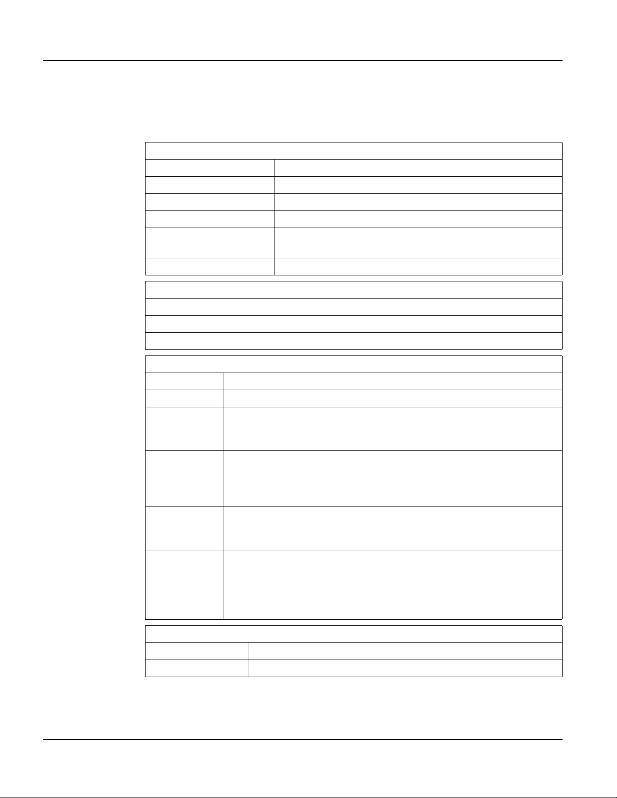
MEMORY
Standard 4 Mbytes flash and 16 Mbytes SDRAM
SPEAKER
Standard Software programmable pitch and duration
Optional Audio (.wav) decoder
REAL-TIME CLOCK
Independent processor-based, real-time clock equipped with a battery back up
PHYSICAL
Configuration Panel-mount
Housing
Size 215 x 161 x 50 mm
Weight 1.16 kg
Processor 200 MHz Intel® XScale™ core platform
Sealing NEMA-4 front panel
Temperature
Humidity 0 to 95%, non-condensing
Vibration 5 to 5000 Hz, 4 g RMS
Shock 20 g, 3 ms, any axis
8 to 26 VDC (See section 1.4.5 for current consumption)
PoE (Power-over-Ethernet)
Well-regulated 5V supply (contact Beijer Electronics)
Programming language Qlarity® (object-based)
Glass-filled polyester, UL 94V-0 flame rating, accommodates panels from
0 to 7 mm thick with standard screws
ENVIRONMENTAL
Operating: -10 to 60
°C, Storage: -20 to 70 °C
POWER
SOFTWARE
Design environment Qlarity Foundry (Windows®)
Command line compiler Qlarify (Win32 or Linux®)
CUSTOMIZING
Outer legend Customize with logo/name or graphics
Inner legend Customize with touch keys and graphics
CERTIFICATION
FCC Part 15, Class A
CE Certification
Qlarity-Based Terminal Hardware 3
Page 16

Supported Interfaces QTERM-G70 Terminal
1.2 Supported Interfaces
1.2.1 Serial Ports
The QTERM-G70 comes standard with one serial port with DB9f connector. The serial port
interface can be EIA-232, EIA-422, or EIA-485. A second serial port is av ailable as an option,
as well as two or four additional full EIA-232 serial ports are also optional.
N
OTE
☞
The primary and auxiliary serial ports are wired as Data Communications Equipment (DCE).
EIA-232
EIA-422 permits operation at distances up to 2,000 meters
EIA-485 permits multiple terminals to be connected in a multi-drop chain
Figure 1 shows the serial connector’s orientation.
The following table shows the pinouts for each type of serial interface.
with proper cables and grounding the terminal can communicate up to
five meters at a top speed of 115,200 bps
Figure 1
QTERM-G70 Serial Connector
Pin 232 422 485
1 — Tx- RTx2TxTx+RTx+
3RxRx+—
4———
5 Ground Ground Ground
6—Rx-—
7CTS (in) —
8RTS (out) —
9 Power Power Power
Power is supplied to the terminal through pin 9 and ground is supplied through p in 5 of the primary serial port connector.
4
Qlarity-Based Terminal Hardware
Page 17
QTERM-G70 Terminal Supported Interfaces
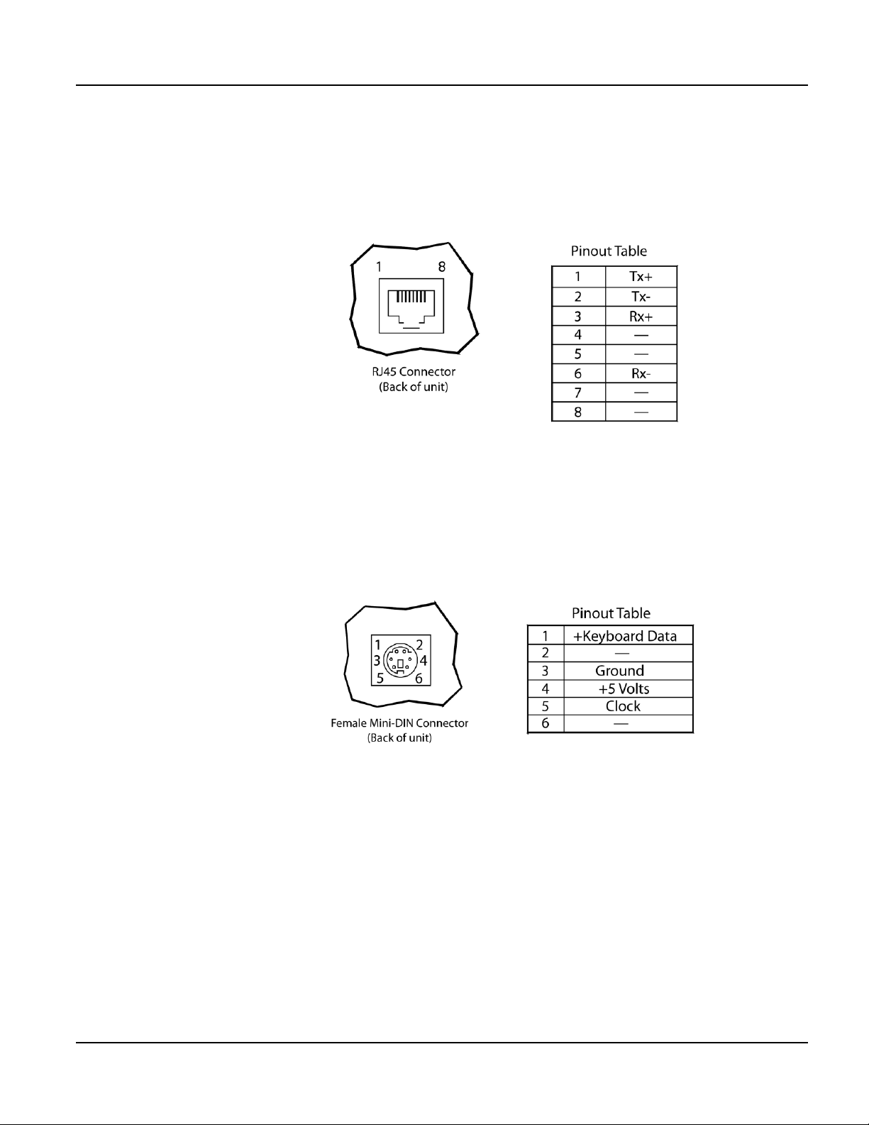
1.2.2 Optional Ethernet Port
The optional Ethernet port has a standard 10/100Base-T interf ace with an 8-pin (RJ-45) modular jack connector and uses TCP/IP protocol. The connector orientation and pinout table are
shown in Figure 2.
Figure 2
QTERM-G70 Ethernet Port Pinouts
1.2.3 Optional PS/2 Keyboard Interface
The optional PS/2 port can be used to connect a standard PS/2 keyboard to the QTERM-G70
terminal. The connector orientation and pinout table are shown in Figure 3.
Figure 3
QTERM-G70 PS/2 Keyboard Interface Pinouts
N
OTE
☞
PS/2 keyboard interface is not available in the terminals with the PoE option.
1.2.4 Optional 5 Volt Power Supply on Secondary Serial Port
The secondary serial port interface (if included) can optionally be configured to provide a 5
volt DC power supply. The supply can provide up to 100 mA current to a serial peripheral
device (such as a barcode reader) connected to COM2. The 5 volt supply is provided on pin 9
and returns to ground on pin 5.
Qlarity-Based Terminal Hardware 5
Page 18
Supported Interfaces QTERM-G70 Terminal
1.2.5 Optional Dual and Quad EIA-232 Serial Port Card
An additional two or four EIA-232 serial ports can be added to the QTERM-G70. These serial
ports have all necessary signals for EIA-232 serial communications and are wired as
Data Terminal Equipment (DTE).
The additional serial port option will add approximately 10 mA to the total current draw of the
terminal plus 15 mA per connected serial cable.
The following table shows the pinouts for the additional serial port option.
Additional EIA-232 Serial Port Pinouts
1DCD (in)
2 Rx (in)
3 Tx (out)
4DTR (out)
5 GND
6 DSR (in)
7RTS (out)
8CTS (in)
9RI (in)
1.2.6 Optional Power-over-Ethernet Module
The optional Power-o ver-Ethernet module allows the user to provide power and communications to the QTERM-G70. The power can be provided from an IEEE 802.3af compliant hub or
switch as well as from a standard power supply.
1.2.6.1 Power Requirements
The optimal power supplied to the QTERM-G70 through the PoE port is 48 VDC, although
the unit will operate with a power input as low as 36 VDC, or as high as 57 VDC (see IEEE
802.3af specification). The power required to operate the terminal without any additional
options is listed below.
Current Consumption
Terminal 48 VDC
G70 STN Idle 120 mA
G70 TFT Idle 190 mA
Active Add +15 mA
6
Qlarity-Based Terminal Hardware
Page 19
QTERM-G70 Terminal Terminal Components
1.2.6.2 Pinouts
In accordance with the PoE standard (IEEE 802.3af), the PoE port is insensitive to polarity of
the power supply and can receive power in either mode A (superimposed on the transmit and
receive twisted pair conductors) or mode B (using the additional tw isted pair conductors). This
yields four possible ways to apply power to the PoE port as shown in the following table. The
table also shows the conductor assignment for the transmit and receive lines as reference.
Port Pin Assignment
Conductor Mode A Mode B
1Tx+/V+Tx+
2Tx-/V+Tx3 Rx+/V- Rx+
4V+
5V+
6 Rx-/V- Rx7V8V-
1.3 Terminal Components
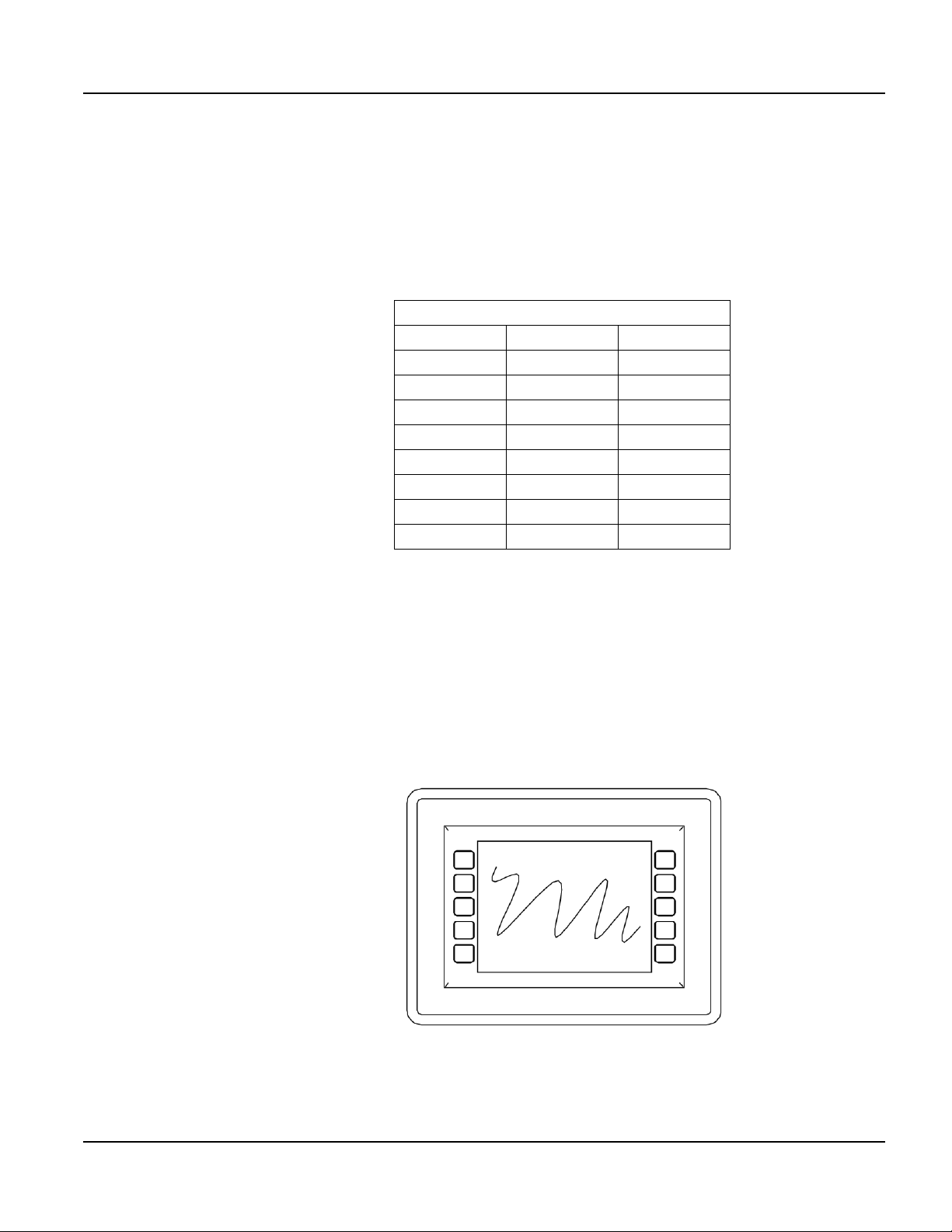
1.3.1 Touch Screen
The QTERM-G70 touch screen provides user input through an y number of touch keys located
on or around the display. The standard key legend shown in Figure 4 provides areas for five
soft keys down each side of the d isp lay. A custom legend underlay can be ordered to personalize the terminal for your application.
Figure 4
QTERM-G70 Standard Key Legend
Qlarity-Based Terminal Hardware 7
Page 20
Terminal Components QTERM-G70 Terminal
Touch keys can also be defined in your user applications at any location on or around the display. Touch keys may be any size.
1.3.2 Keyboard
Using the optional PS/2 port, a standard PC keyboard may be used in addition to, or in place
of, the touch screen. Power On Setup, the terminal setup utility, recognizes both touch keys
and keyboard keys.
1.3.3 Keypad
The QTERM-G70 terminal can optionally include electronics for attaching an external ke ypad
with up to 8 columns by 8 rows and up to 6 keypad LEDs. Co ntact Beijer Electronics for mor e
information.
The keypad option will add 10 mA to the total current draw of the terminal plus the current
driven out the LED outputs pins. The LED outputs are five-volt open-collector signals with a
1000 Ohm series resistor. This results in an approximate maximum output current drive of 5
mA on those pins. There are two connectors on the keypad module to facilitate connecting different sized keypads. The pinouts for those connectors are shown in the following tables.
Connector J1 - 0.1 Inch Pitch
16-pin Single-row Connector
1 GND 9 Row 5
2 LED 1 10 Row 6
3Row 111Col 1
4Row 212Col 2
5Row 313Col 3
6Row 414Col 4
7 GND 15 Col 5
8 LED 2 16 Col 6
Connector J2 - 0.1 Inch Pitch
24-pin Dual-row Connector
1Row 113Col 1
2 5 V or 3.3 V 14 LED 4
3Row 215Col 2
4 GND 16 LED 3
5Row 317Col 3
6 LED 6 18 LED 2
7Row 419Col 4
8 LED 5 20 LED 1
8
Qlarity-Based Terminal Hardware
Page 21
QTERM-G70 Terminal Terminal Components
Connector J2 - 0.1 Inch Pitch
24-pin Dual-row Connector
9Row 521Col 5
10 Row 8 22 Col 6
11 Row 6 23 Col 8
12 Row 7 24 Col 7
1.3.4 Speaker
A speaker is built into the QTERM-G70 terminal and faces to the back of the unit. Audio can
be linked to events or actions (e.g., screen press, timer, etc.). Pitch and duration of a sound are
controlled by API functions called from the user application. Refer to “Controlling the
Speaker” section in the Qlarity-based Terminal Programmer's Reference Manual.
Optionally, an audio (.wav) decoder can be added to the QTERM-G70 to allow the speaker to
play audio files. The audio decoder supports wave files meeting the following criteria:
• Sample rate of 8 kHz, 11.025 kHz, 16 kHz or 22.050 kHz
• Resolution of 8 or 16 bits per sample.
The audio decoder circuit amplifies the signal to 0.5 W rms at the speaker .
1.3.5 Real-Time Clock
The QTERM-G70 terminal is equipped with a battery-backed , real-tim e clo ck . The real-ti me
clock can be used to time/date stamp messages or for timed polling and program execution.
WARNING
There may be danger of leakage if the battery is incorrectly replaced, creating a potential
health hazard. Replace the battery only with the same (CR1220) or equivalent type as recommended by the manufacturer. Dispose of used batteries according to the manufacturer’s
instructions.
1.3.6 System Memory
The QTERM-G70 terminal stores the firmware and user applications in a compressed format
in flash memory and then transfers them to RAM memory when the terminal is powered on.
Four megabytes of flash memory and sixteen megabytes of RAM memory are standard.
For information on using resources efficiently to conserve memory when creating a user application, refer to “Edit Resources” section in the Qlarity Foundry User Guide.
Qlarity-Based Terminal Hardware 9
Page 22

Installing to NEMA-4 QTERM-G70 Terminal
For information on downloading new f irmw are, downloading a user application, and determining the size of a user application, refer to the Qlarity Foundry User Guide.
1.3.7 Watchdog Timer
A watchdog timer can be added to enforce proper operation of the QTERM-G70. The watchdog timer will reset the terminal if there is a problem that causes the firmware to lock up. This
does not apply to software deadlocks in the Qlarity code. If that is required, then the Qlarity
watchdog timer should be used, using the WatchdogEnable and WatchdogReset APIs.
1.4 Installing to NEMA-4
A QTERM-G70 terminal uses a rugged, glass-filled polyester (UL 94V-0) case designed to
mount into a panel or drywall. When properly installed in a NEMA-4 rated panel, the
QTERM-G70 meets all NEMA-4 specifications including hose-down, icing, and salt spray.
A QTERM-G70 terminal can be installed in either a landscape or portrait orientation. When
installing a terminal, you generally take the following steps.
• Decide whether you want to mount and use the terminal in a portrait or landscape orienta-
tion. “Portrait” means that the longest dimension is vertical; “landscape” means that the
longest dimension is horizontal.
• Cut a hole in the panel or drywall. See section 1.4.1, “Cutout for Panel Mount Configura-
tion” or section 1.4.3, “Cutout for Drywall Mount Configuration” for specifications.
• Install the QTERM-G70 terminal in the panel or drywall. See section 1.4.2, “Installing the
Panel Mount Terminal” or section 1.4.4, “Installing the Drywall Mount Terminal” for
instructions.
• Connect cables to the terminal. Verify that the thumb screws are tight or the locks snapped
into place for each cable used.
• Apply DC power to the QTERM-G70 terminal. See section 1.4.5, “Applying Power” for
information.
1.4.1 Cutout for Panel Mount Configuration
The QTERM-G70 terminal can be mounted in panels from 0 to 7 mm thick. No screw holes
need to be drilled to install the terminal in the panel.
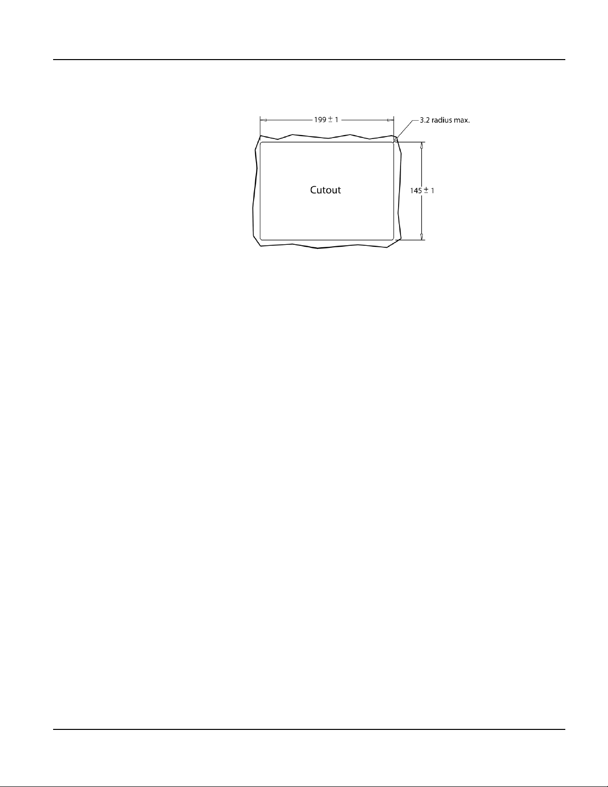
Make a rectangular hole in the panel using the following dimensions.
10
Landscape Portrait
Horizontal: 199 ± 1 mm Horizontal: 145 ± 1 mm
Vertical: 145 ± 1 mm Vertical: 199 ± 1 mm
Qlarity-Based Terminal Hardware
Page 23
QTERM-G70 Terminal Installing to NEMA-4
Figure 5 is a diagram of the landscape cutout.
Figure 5
QTERM-G70 Landscape Cutout
File any rough edges smooth, especially on the face of the panel.
1.4.2 Installing the Panel Mount Terminal
NOTE
☞
Use of an anti-static strap is recommended when performing installation and maintenance.
Take the following steps to install the terminal.
1. Verify that the panel surface around the cutout is clean and free of rough edges. A gasket
built into the terminal will seal against this surface. Dirt or imperfections on the panel may
prevent a proper seal.
2. Place the terminal into the panel cutout and verify that the terminal is oriented correctly.
The touch screen legend may indicate the orientation. If not, you can determine which side
should be at the top by the position of the serial port on the back panel as follows:
• Landscape
When looking at the front of the unit, the back panel serial port(s) should be on the bottom of the terminal.
• Portrait
When looking at the front of the unit, the back panel serial port(s) should be on the left
side of the terminal.
Refer to Figure 6.
Qlarity-Based Terminal Hardware 11
Page 24

Installing to NEMA-4 QTERM-G70 Terminal
Figure 6
QTERM-G70 Front Panel Mount
3. On the back of the panel, place the terminal mounting bracket against the back of the terminal, and align it with the back panel. Refer to Figure 7.
12
Figure 7
QTERM-G70 Back Panel Mount
4. Fasten the six screws (supplied with the terminal).
Qlarity-Based Terminal Hardware
Page 25

QTERM-G70 Terminal Installing to NEMA-4
1.4.3 Cutout for Drywall Mount Configuration
The QTERM-G70 terminal with the drywall mount configuration will accommodate drywall
thicknesses of 7 mm to 18 mm. The panel may be cut by using the template supplied with the
unit or by using the dimensions given below. To use the template, simply identify where the
unit is to be placed on the wall and tape the template up into position. Next cut along the indicated line. The cutout dimensions with appropriate tolerances are as follows.
Landscape Portrait
Horizontal: 199 ± 1 mm Horizontal: 145 ± 1 mm
Vertical: 145 ± 1 mm Vertical: 199 ± 1 mm
N
OTE
☞
Care must be taken not to make the cutout oversize.
1.4.4 Installing the Drywall Mount Terminal
NOTE
☞
Use of an anti-static strap is recommended when performing installation and maintenance.
Take the following steps to install the terminal. Refer to Figure 8.
Figure 8
QTERM-G70 Drywall Mount
1. Verify that the unit is in the correct orientation. The touchscreen legend may indicate the
orientation. If not, the top side may be identified by the position of the serial port(s) on the
back panel as follows:
Qlarity-Based Terminal Hardware 13
Page 26

Installing to NEMA-4 QTERM-G70 Terminal
• Landscape
When looking at the front of the unit, the back panel serial port(s) should be on the bottom of the terminal.
• Portrait
When looking at the front of the unit, the back panel serial port(s) should be on the left
side of the terminal.
2. Connect all necessary cables to their correct places on the back panel.
3. Insert the terminal into the cutout in the wall. If the uni t will not fit int o the opening, check
to make sure that the cam locks on the top and bottom are not protruding from the case.
4. Tighten all four screws on the front panel until the unit seats firmly in the cutout. The
screws should be tightened approximately 2-3 full turns after a slight resistance is felt.
N
OTE
☞
Do not over tighten the screws. Doing so wi ll damag e the cam locks and the unit will no long er
mount securely into the wall.
5. Using the supplied legend, remove the adhesive back and install on the front of the unit
over the top of the four screws as indicated in the figure.
1.4.4.1 Removing the Drywall Mount Terminal
Removal of the G70 terminal requires the replacement of the outer legend. Replacements may
be ordered from Beijer Electronics.
1. Remove the outer legend on the front of the unit to expose the four mounting screws.
2. Turn the screws counterclockwise until they begin to back out of the unit.
3. Gently pull the terminal from the wall cutout.
1.4.5 Applying Power
Power is supplied to the QTERM-G70 terminal via the primary serial port connector. Refer to
section 1.2.1, “Serial Ports” for power and ground pin assignments. DC power must be in the
range of 8 to 26 volts (the current will vary depending on the input voltage; see table below).
14
CAUTION
QTERM-G70 power must come from an SELV (Safety Extra Low Voltage) power source
and should have a current limit on its output of 5 Amperes. It must provide a minimum of 8
volts DC power and be limited to a maximum of 26 volts DC. Limiting may be inherent to
the supply or may be provided by supplementary overcurrent devices. If the QTERM-G70
does not respond or exhibits abnormal behavior on power up, disconnect power and contact
Beijer Electronics for technical support.
Qlarity-Based Terminal Hardware
Page 27

QTERM-G70 Terminal Powering On the Terminal for the First Time
Current Consumption
Terminal 12 VDC 24 VDC PoE
Standard unit (color, no op tion s, idle) 400 mA 240 mA 120 mA
Standard TFT unit (TFT, no options, idle) 675 mA 350 mA 190 mA
Standard unit, active add 90 mA add 40 mA add 15 mA
Standard TFT unit, active add 90 mA add 50 mA add 15 mA
With keyboard option and keyboard attached add 70 mA add 35 mA N/A
With Ethernet option and connection add 40 mA add 20 mA N/A
1.5 Powering On the Terminal for the First Time
When you connect power to the QTERM-G70 terminal, it automatically loads the application
saved in flash memory into RAM memory and executes the application. If no application is
present, the terminal display may be blank but the backlighting verifies it is powered on.
When you power on the terminal for the f irst time, a demo application (or a special appli cation
custom designed for your company) loads. The demo application will help you verify that the
terminal is operating properly. Follow the on-screen prompts or any documentation accompanying the program to guide you through tests or demonstrations designed to verify terminal
operation.
Once you have v erified that the terminal is functioning properly, refer to Chapter 8, “Power On
Setup” for information on configuring your terminal. The Power On Setup utility includes
functions to do the following:
• Change orientation of the terminal (portrait or landscape)
• Download a new user application to the terminal
• Select the application mode
• Set up communications settings for the terminal
• Adjust display contrast or backlight
• Enter network (Ethernet) settings
• Enter/change password (if used)
• Set the real-time clock
Qlarity-Based Terminal Hardware 15
Page 28

Powering On the Terminal for the First Time QTERM-G70 Terminal
Notes
16
Qlarity-Based Terminal Hardware
Page 29

CHAPTER 2
QTERM-G75 TERMINAL
2.1 Product Description
The QTERM-G75 terminal is a large display Ethernet-enabled graphic terminal with
object-based programming. It features a robust list of industrial grade hardware features and
options.
The QTERM-G75 features a VGA, 640x480 pixel, active-matrix TFT LCD display (256 colors). It uses a dual lamp cold-cathode fluorescent backlight (CCFL). The CCFL provides high
contrast and easy readability and is replaceable. The analog-resistive touch screen covers the
full viewable area of the display as well as the pre-labeled legend underlay on each side of the
display.
The QTERM-G75 comes equipped with one serial port using an EIA-232, EIA-422, or
EIA-485 interface. A second serial port, an Ethernet port, and a PS/2 keyboard port are available as options.
Possible input devices include the touch screen and attachable ke yboard (with an optional PS/2
connector). Custom configurations of the QTERM-G75 can also support an e xte rnal ke yp ad, a
dual EIA-232 full serial port card or a quad EIA-232 full serial port card (contact Beijer Electronics for details). A speaker, which has programmable pitch and duration, co mes standard, as
does a battery-backed real-time clock. Other options include: an audio decoder for playing
audio wave files, a hardware watchdog timer, and a 5 V/100 mA output from the auxiliary
serial port to power external devices.
The QTERM-G75 terminal stores the firmware and the user application in a compressed format in flash memory and then transfers them to RAM memory when the terminal is powered
on. The terminal is equipped with eight megabytes of flash memory and 32 megabytes of
RAM memory . The Power-ov e r-Ethernet units is equipped with four megabytes of flash memory and sixteen megabytes of RAM.
The outer legend can be customized with your logo/name or graphics. The inner le gend un derlay around the display can be customized with your touch keys and graphics.
The QTERM-G75 terminal requires a DC power source in a range of 8 to 26 VDC. This power
is supplied via the main DB9 serial connector. Other options for supplying power to the
QTERM-G75 are PoE (Power-o v er -Ethernet) or f ive volts from a well-regulated power supply
via the main DB9 serial connector. Please contact Beijer Electronics for more information
about this option.
Qlarity-Based Terminal Hardware 17
Page 30
Product Description QTERM-G75 Terminal
2.1.1 Specifications
The following tables contain the technical specifications for the QTERM-G75.
TERMINAL DISPLAY
Active Matrix (standard) TFT 256 colors
Enhanced TFT (optional) Enhanced TFT 256 colors
Pixels 640 x 480
Dot pitch 0.33 mm
Lighting
Backlight brightness TFT 550 nits typical, enhanced TFT 800 nits typical
Analog-resistive operation
Transparent touch area over viewable display
Dual lamp cold-cathode fluorescent, brightness software-controllable
TOUCH SCREEN
Labeled touch underlay area on each side of d isplay
INTERFACE
Standard EIA-232 serial port with hardware or software handshaking
Baud rates 600 – 115,200 bps
None
Flow control
Data formats
Connector
Options
XonXoff (software)
RTS/CTS (hardware)
7 or 8 data bits
1 or 2 stop bits
Even, odd, or no parity
(PC Tools support only 8 data bits)
DB9f (2 with optional second serial port)
8-pin modular (RJ45) with Ethernet option
PS/2 keyboard connector (optional)
Primary serial port configurable as EIA-232, EIA-422, or EIA-485
Secondary serial port available (EIA-232, EIA-422, or EIA-485)
Ethernet 10/100Base-T with support for TCP/IP networking
PS/2 keyboard port
Additional dual or quad full EIA-232 serial port cards available
18
MEMORY
Standard 8 Mbytes flash and 32 Mbytes SDRAM
PoE 4 Mbytes flash and 16 Mbytes SDRAM
Qlarity-Based Terminal Hardware
Page 31

QTERM-G75 Terminal Product Description
SPEAKER
Standard Software programmable pitch and duration
Optional Audio (.wav) decoder
REAL-TIME CLOCK
Independent processor-based, real-time clock equipped with a battery back up
PHYSICAL
Configuration Panel-mount
Housing
Size 330 x 260 x 55.3 mm
Weight 2.9 kg
Aluminum, accommodates panels from 0 to 12 mm thick with standard
screws
Processor
Sealing NEMA-4 front panel
Temperature
Humidity 0 to 95%, non-condensing
V ib r ation 5 to 5000 Hz, 4 g RMS
Shock 20 g, 3 ms, any axis
8 to 26 VDC (See section 2.4.3 for current consumption)
PoE (Power-over-Ethernet)
Programming language Qlarity (object-based)
Design environment Qlarity Foundry (Windows)
Command line compiler Qlarify (Win32 or Linux)
400 MHz Intel XScale core (standard)
200 MHz Intel XScale core (PoE)
ENVIRONMENTAL
Operating: -10 to 60
Storage: -20 to 70 °C
°C
POWER
SOFTWARE
CUSTOMIZING
Outer legend Customize with logo/name or graphics
Inner legend Customize with touch keys and graphics
CERTIFICATION
FCC Part 15, Class A
CE Certification
Qlarity-Based Terminal Hardware 19
Page 32

Supported Interfaces QTERM-G75 Terminal
2.2 Supported Interfaces
2.2.1 Serial Ports
The QTERM-G75 comes standard with one serial port with DB9f connector. The serial port
interface can be EIA-232, EIA-422, or EIA-485. A second serial port is av ailable as an option,
as well as two or four additional full EIA-232 serial ports are also optional.
N
OTE
☞
The primary and auxiliary serial ports are wired as Data Communications Equipment (DCE).
EIA-232
EIA-422 permits operation at distances up to 2,000 meters
EIA-485 permits multiple terminals to be connected in a multi-drop chain
Figure 9 shows the serial connector’s orientation.
The following table shows the pinouts for each type of serial interface.
with proper cables and grounding the terminal can communicate up to five
meters at a top speed of 115,200 bps
Figure 9
QTERM-G75 Serial Connector
Pin 2 32 422 485
1 — Tx- RTx2 Tx Tx+ RTx+
3Rx Rx+ —
4———
5 Ground Ground Ground
6— Rx- —
7CTS (in) —
8RTS (out) —
9 Power Power Power
20
Power is supplied to the terminal through pin 9 and ground is supplied through p in 5 of the primary serial port connector.
Qlarity-Based Terminal Hardware
Page 33

QTERM-G75 Terminal Supported Interfaces
2.2.2 Optional Ethernet Port
The optional Ethernet port has a standard 10/100Base-T interf ace with an 8-pin (RJ-45) modular jack connector and uses TCP/IP protocol. The connector orientation and pinout table are
shown in Figure 10.
Figure 10
QTERM-G75 Ethernet Port Pinouts
2.2.3 Optional PS/2 Keyboard Interface
The optional PS/2 port can be used to connect a standard PS/2 keyboard to the QTERM-G75
terminal. The connector orientation and pinout table are shown in Figure 11.
Figure 11
QTERM-G75 PS/2 Keyboard Interface Pinouts
2.2.4 Optional 5 Volt Power Supply on Secondary Serial Port
The secondary serial port interface (if included) can optionally be configured to provide a 5
volt DC power supply. The supply can provide up to 100 mA current to a serial peripheral
device (such as a barcode reader) connected to COM2. The 5 volt supply is provided on pin 9
and returns to ground on pin 5.
Qlarity-Based Terminal Hardware 21
Page 34

Terminal Components QTERM-G75 Terminal
2.2.5 Optional Dual and Quad EIA-232 Serial Port Card
An additional two or four EIA-232 serial ports can be added to the QTERM-G75. These serial
ports have all necessary signals for EIA-232 serial communications and are wired as
Data Terminal Equipment (DTE).
The additional serial port option will add approximately 10 mA to the total current draw of the
terminal plus 15 mA per connected serial cable.
The following table shows the pinouts for the additional serial port option.
Additional EIA-232 Serial Port Pinouts
1DCD (in)
2 Rx (in)
3 Tx (out)
4DTR (out)
5 GND
6 DSR (in)
7 RTS (out)
8CTS (in)
9 RI (in)
2.2.6 Optional Power-over-Ethernet Module
The optional Power-o ver-Ethernet module allows the user to provide power and communications to the QTERM-G75. The power can be provided from an IEEE 802.3af compliant hub or
switch as well as from a standard power supply.
2.3 Terminal Components
2.3.1 Touch Screen
The QTERM-G75 touch screen provides user input through an y number of touch keys located
on or around the display. The standard key legend shown in Figure 12 provides areas for five
soft keys down each side of the d isp lay. A custom legend underlay can be ordered to personalize the terminal for your application.
22
Qlarity-Based Terminal Hardware
Page 35

QTERM-G75 Terminal Terminal Components
Touch keys can also be defined in your user applications at any location on or around the display. Touch keys may be any size.
2.3.2 Keyboard
Using the optional PS/2 port, a standard PC keyboard may be used in addition to, or in place
of, the touch screen. Power On Setup, the terminal setup utility, recognizes both touch keys
and keyboard keys.
2.3.3 Keypad
The QTERM-G75 terminal can optionally include electronics for attaching an external ke ypad
with up to 8 columns by 8 rows and up to 6 keypad LEDs. Co ntact Beijer Electronics for more
information.
The keypad option will add 10 mA to the total current draw of the terminal plus the current
driven out the LED outputs pins. The LED outputs are five-volt open-collector signals with a
1000 Ohm series resistor. This results in an approximate maximum output current drive of 5
mA on those pins. There are two connectors on the keypad module to facilitate connecting different sized keypads. The pinouts for those connectors are shown in the following table.
Figure 12
QTERM-G75 Standard Key Legend
Qlarity-Based Terminal Hardware 23
Page 36

Terminal Components QTERM-G75 Terminal
Connector J1 - 0.1 Inch Pitch
16-pin Single-row Connector
1 GND 9 Row 5
2 LED 1 10 Row 6
3Row 111Col 1
4Row 212Col 2
5Row 313Col 3
6Row 414Col 4
7 GND 15 Col 5
8 LED 2 16 Col 6
Connector J2 - 0.1 Inch Pitch
24-pin Dual-row Connector
1Row 113Col 1
2 5 V or 3.3 V 14 LED 4
3Row 215Col 2
4 GND 16 LED 3
5Row 317Col 3
6 LED 6 18 LED 2
7Row 419Col 4
8 LED 5 20 LED 1
9Row 521Col 5
10 Row 8 22 Col 6
11 Row 6 23 Col 8
12 Row 7 24 Col 7
2.3.4 Speaker
24
A speaker is built into the QTERM-G75 terminal and faces to the back of the unit. Audio can
be linked to events or actions (e.g., screen press, timer, etc.). Pitch and duration of a sound are
controlled by API functions called from the user application. Refer to “Controlling the
Speaker” section in the Qlarity-based Terminal Programmer's Reference Manual.
Optionally, an audio (.wav) decoder can be added to the QTERM-G75 to allow the speaker to
play audio files. The audio decoder supports wave files meeting the following criteria:
• Sample rate of 8 kHz, 11.025 kHz, 16 kHz or 22.050 kHz
• Resolution of 8 or 16 bits per sample.
The audio decoder circuit amplifies the signal to 0.5 W rms at the speaker .
Qlarity-Based Terminal Hardware
Page 37

QTERM-G75 Terminal Installing to NEMA-4 Specifications
2.3.5 Real-Time Clock
The QTERM-G75 terminal is equipped with a battery-backed , real-tim e clo ck . The real-ti me
clock can be used to time/date stamp messages or for timed polling and program execution.
WARNING
There may be danger of leakage if the battery is incorrectly replaced, creating a potential
health hazard. Replace the battery only with the same (CR1220) or equivalent type as recommended by the manufacturer. Dispose of used batteries according to the manufacturer’s
instructions.
2.3.6 System Memory
The QTERM-G75 terminal stores the firmware and user applications in a compressed format
in flash memory and then transfers them to RAM memory when the terminal is powered on.
Eight megabytes of flash memory and 32 megabytes of RAM memory are included on the
standard unit. The PoE unit has four megabytes of flash memory and sixteen megabytes of
RAM memory.
For information on using resources efficiently to conserve memory when creating a user application, refer to “Edit Resources” section in the Qlarity Foundry User Guide.
For information on downloading new f irmw are, downloading a user application, and determining the size of a user application, refer to the Qlarity Foundry User Guide.
2.3.7 Watchdog Timer
A watchdog timer can be optionally added to enforce proper operation of the QTERM-G75.
The watchdog timer will reset the terminal if there is a problem causing the firmware to lock
up. This does not apply to software deadlocks in the Qlarity code. If that is required, then the
Qlarity watchdog timer should be used, using the WatchdogEnable and WatchdogReset APIs.
2.4 Installing to NEMA-4 Specifications
A QTERM-G75 terminal uses a rugged aluminum case designed to mount into a panel. When
properly installed in a NEMA-4 rated panel, the QTERM-G75 meets all NEMA-4 specifications including hose-down, icing, and salt spray.
A QTERM-G75 terminal can be installed with either landscape or portrait orientation. When
installing a terminal, you generally take the following steps.
• Decide whether you want to mount and use the terminal in portrait or landscape orientation.
“Portrait” means that the longest dimension is vertical; “landscape” means that the longest
dimension is horizontal.
Qlarity-Based Terminal Hardware 25
Page 38

Installing to NEMA-4 Specifications QTERM-G75 Terminal
• Cut a hole in the panel and drill the mounting holes. See section 2.4.1, “Cutting Out the
Panel” for specifications.
• Install the QTERM-G75 terminal in the panel. See section 2.4.2, “Installing the Terminal”
for instructions.
• Connect cables to the terminal. Verify that the thumb screws are tight or the locks snapped
into place for each cable used.
• Apply DC power to the QTERM-G75 terminal. See section 2.4.3, “Applying Power” for
information.
2.4.1 Cutting Out the Panel
The QTERM-G75 terminal can be mounted in panels from 0 to 12 mm thick. Fourteen screw
holes need to be drilled to install the terminal in the panel. The mounting holes should be 4.6
mm in diameter and drilled as shown in the figure below . Mak e a rectangular hole in the panel
using the following dimensions.
Landscape Portrait
Horizontal: 291 ± 1 mm Horizontal: 221 ± 1 mm
Vertical: 221 ± 1 mm Vertical: 291 ± 1 mm
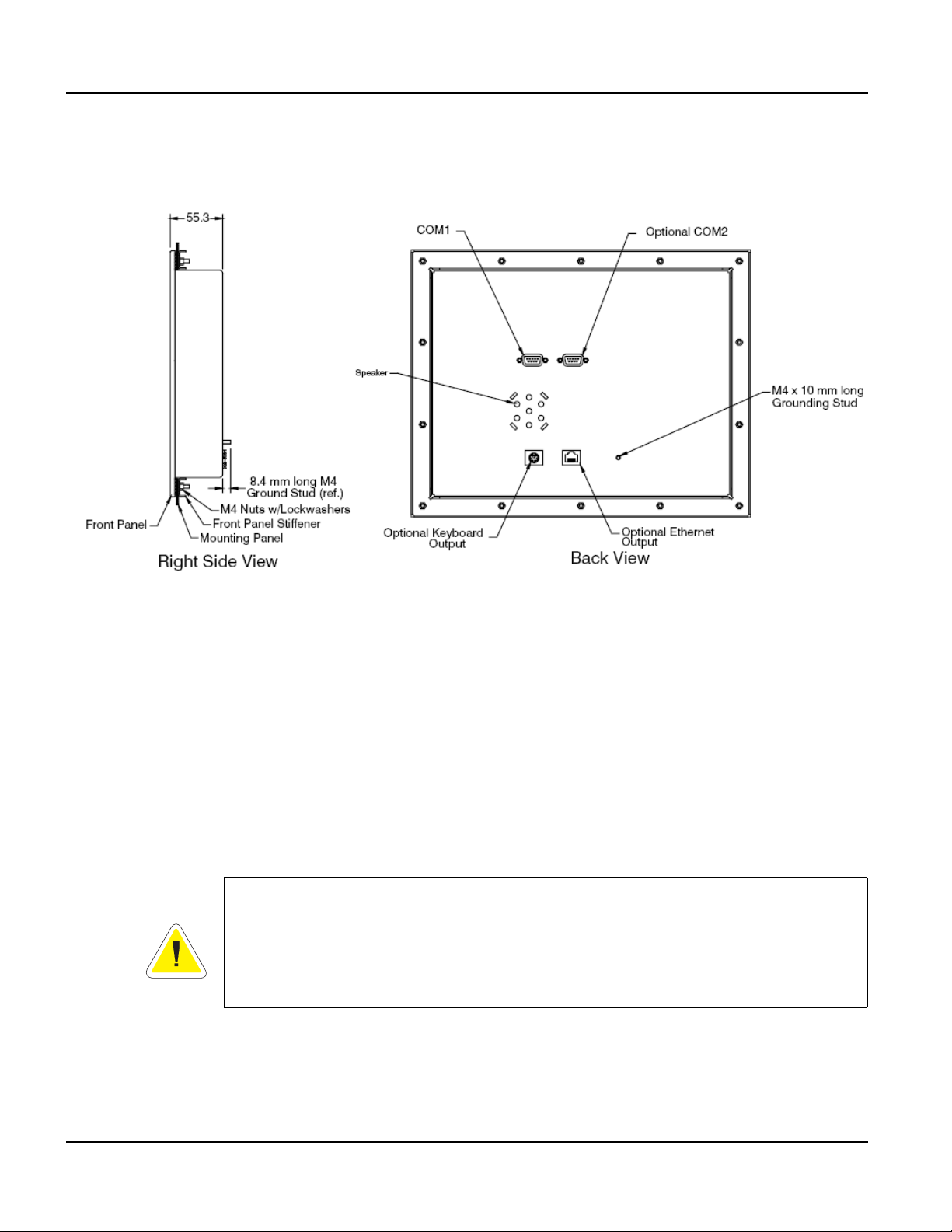
Figure 13 is a diagram of the landscape cutout.
Figure 13
QTERM-G75 Landscape Cutout
26
File any rough edges smooth, especially on the face of the panel.
Qlarity-Based Terminal Hardware
Page 39

QTERM-G75 Terminal Installing to NEMA-4 Specifications
2.4.2 Installing the Terminal
Take the following steps to install the terminal.
1. Verify that the panel surface around the cutout and mounting holes is clean and free of
rough edges. A gasket built into the terminal will seal against this surface. Dirt or imperfections on the panel may prevent a proper seal.
2. Place the terminal into the panel cutout (inserting the studs into the mounting holes) and
verify that the terminal is oriented correctly. The touch screen legend may indicate the orientation. If not, you can determine which side should be at the top by the position of the
serial port on the back panel as follows:
• Landscape
When looking at the front of the unit, the back panel serial port(s) should be near the top
of the terminal.
• Portrait
When looking at the front of the unit, the back panel serial port(s) should be on the right
side of the terminal.
Refer to Figure 14.
Figure 14
QTERM-G75 Front Panel Mount
Qlarity-Based Terminal Hardware 27
Page 40
Installing to NEMA-4 Specifications QTERM-G75 Terminal
3. On the back of the panel, align the terminal mounting bracket holes with the mounting
studs and place the bracket against the back of the panel. Refer to Figure 15.
4. Attachments with lockwashers (supplied with the terminal) onto each of the fourteen
mounting studs. Tighten all nuts to create the seal betwee n the terminal gasket and the
panel. Avoid overtightening the nuts.
2.4.3 Applying Power
Power is supplied to the QTERM-G75 terminal via the primary serial port connector. Refer to
section 2.2.1, “Serial Ports” for the pin assignments for po wer and ground . DC power must be
in the range of 8 to 26 volts (the current will vary depending on the input voltage; see table
below).
CAUTION
QTERM-G75 power must come from an SELV (Safety Extra Low Voltage) power source
and should have a current limit on its output of 5 Amperes. It must provide a minimum of 8
volts DC power and be limited to a maximum of 26 volts DC. Limiting may be inherent to
the supply or may be provided by supplementary overcurrent devices. If the QTERM-G75
does not respond or exhibits abnormal behavior on power up, disconnect power and contact
Beijer Electronics for technical support.
Figure 15
QTERM-G75 Back Panel Mount
28
Qlarity-Based Terminal Hardware
Page 41

QTERM-G75 Terminal Installing to NEMA-4 Specifications
Current Consumption
Terminal 12 VDC 24 VDC
Standard unit idle 950 mA 475 mA
Enhanced unit idle 1.0 A 500 mA
Standard unit, active add 100 mA add 60 mA
Enhanced unit, active add 100 mA add 60 mA
With keyboard option and keyboard attached add 70 mA add 35 mA
With Ethernet option and connection add 40 mA add 20 mA
2.4.4 Powering On the Terminal for the First Time
When you connect power to the QTERM-G75 terminal, it automatically loads the application
saved in flash memory into RAM memory and executes the application. If no application is
present, the terminal display is blank but the back-lighting verifies that it is powered on.
When you power on the terminal for the f irst time, a demo application (or a special appli cation
custom designed for your company) loads. The demo application will help you verify that the
terminal is operating properly. Follow the on-screen prompts or any documentation accompanying the program to guide you through tests or demonstrations designed to verify terminal
operation.
Once you have v erified that the terminal is functioning properly, refer to Chapter 8, “Power On
Setup” for information on configuring your terminal. The Power On Setup utility includes
functions to do the following:
• Change orientation of the terminal (portrait or landscape)
• Download a new user application to the terminal
• Select the application mode
• Set up communications settings for the terminal
• Adjust display contrast or backlight
• Enter network (Ethernet) settings
• Enter/change password (if used)
• Set the real-time clock
Qlarity-Based Terminal Hardware 29
Page 42

Installing to NEMA-4 Specifications QTERM-G75 Terminal
Notes
30
Qlarity-Based Terminal Hardware
Page 43

CHAPTER 3
QTERM-G55 TERMINAL
3.1 Product Description
The QTERM-G55 is a rugged, handheld or panel-mount Ethernet-enabled graphic terminal
with object-based programming. It features a robust list of industrial grade hardware features
and options.
The QTERM-G55 features a QVGA, 320x240 pixel, LCD transflective FSTN, grayscale (16
shades) display or optional active-matrix TFT (256 colors) display. Both displays use a light
emitting diode (LED) backlight. The LED provides reasonable contrast at low power consumption and easy readability . The FSTN contrast is softw are-controlled and compensated for
temperature. The transflective display provides excellent contrast in sunlight and high ambient
light environments.
The QTERM-G55 comes equipped with one serial port using an EIA-232, EIA-422, or
EIA-485 interface. A second serial port or an Ethernet or Power-over-Ethernet port are available as options. Units with the emergency stop (E-stop) option may be equipped with a single
serial port, Ethernet or Power-over-Ethernet.
User input occurs through a rugged 24-key or 40-key membrane keypad with steel snap
domes. The top row of keys are commonly used as soft keys to navigate through a set of
changing menus at the bottom of the display. The standard keypad comes with four or five
LEDs under the soft keys that can be used as status or alarm indicators. Power and shift buttons with LEDs are included on both keypad configurations. The power button puts the terminal into a sleep mode for low power consumption and provides instant-on function with no
loss of program state.
The 40-key keypad allows for function / softkeys, eight-way directional control and numeric
entry in the unshifted mode and alphanumeric data entry in the shifted mode. Keys can perform alternate functions when the shift key is enabled. Both the power and shift functions can
be enabled or disabled in software.
The keypad legend can be customized with your logo/name and custom keys.
The QTERM-G55 terminal stores the firmware and the user application in a compressed format in flash memory and then transfers them to RAM memory when the terminal is powered
on. The terminal is equipped with two megabytes of flash memory and sixteen megabytes of
RAM memory.
The QTERM-G55 terminal includes a switching power supply with a wide input voltage range
of 8 to 32 VDC. Typically, power is supplied thro ug h th e 1 2-pin circular con nect or or i ntegral
cable (handheld) or the primary serial port (panel-mount). If the Power-over-Ethernet (PoE)
option is selected, power is supplied through the Ethernet cable and your PoE-compliant hub.
Qlarity-Based Terminal Hardware 31
Page 44

Product Description QTERM-G55 Terminal
3.1.1 Specifications
The following tables contain the technical specifications for the QTERM-G55.
TERMINAL DISPLAY
Grayscale (standard) FSTN 16 shades of gray
Active Matrix Color (optional) TFT 256 colors
Pixels 320 x 240
Dot Pitch
FSTN Contrast Software-controlled, temperature compensated
Lighting Light emitting diode brightness is software-controllable
Backlight Brightness
24- or 40-keys
Steel snap domes in membrane
Lighted keypad with electroluminescent lighting (optional)
Optional emergency stop switch (2-pole, normally closed)
Standard EIA-232 serial port with hardware or software handshaking
Baud rates 600 – 115,200 bps
None
Flow control
Data formats
Connector
Options
XonXoff (software)
RTS/CTS (hardware)
7 or 8 data bits
1 or 2 stop bits
Even, odd, or no parity
(PC Tools support only 8 data bits)
Handheld - 12-pin round (Hirose HR30-8R-12SC)
Integral cable with DB15f
Panel-mount - DB9f (2 with optional second serial port)
8-pin modular (RJ45) with Ethernet option
Primary serial port configurable as EIA-232, EIA-422, or EIA-485
Secondary serial port available (EIA-232, EIA-422, or EIA-485)
Ethernet 10Base-T with support for TCP/IP networking
Power-over-Ethernet
FSTN 0.24 mm
TFT 0.227 mm
FSTN 10 nits typical
TFT 200 nits typical
KEYPAD
INTERFACE
32
Qlarity-Based Terminal Hardware
Page 45

QTERM-G55 Terminal Product Description
MEMORY
Standard 2 Mbytes flash and 16 Mbytes SDRAM
SPEAKER
Standard Software programmable pitch and duration
Optional Audio (.wav) decoder
REAL-TIME CLOCK
Optional Independent processor-based, real-time clock equipped with a battery backup
PHYSICAL
Configuration
Housing
Panel-mount
Handheld
Handheld - ABS/bicarbonate case with molded rubber boot
Panel-mount - ABS/poly carbonate case with rubber overmold trim
Size
Mass
Processor ARM720T 77 Mhz
Sealing
Temperature
Humidity 0 to 95%, non-condensing
Vibration 5 to 2000 Hz, 4 g RMS
Shock 20 g, 3 ms, any axis
8 to 32 VDC (See section 3.4.3 for current consumption)
PoE (Power-over-Ethernet)
Handheld - 129 x 234 x 43 mm
Panel-mount - 127 x 228.6 x 95.6 mm
Handheld - 520 g
Panel-mount
- 700 g
ENVIRONMENTAL
Handheld - NEMA-12 (Standard)
NEMA-4 (optional)
Panel-mount - NEMA-4
Operating: -20 to 60
Storage: -40 to 85 °C
POWER
°C
SOFTWARE
Programming language Qlarity (object-based)
Design environment Qlarity Foundry (Windows)
Command line compiler Qlarify (Win32 or Linux)
Qlarity-Based Terminal Hardware 33
Page 46

Supported Interfaces QTERM-G55 Terminal
CUSTOMIZING
Keypad legend Customize with logo/name or graphics
CERTIFICATION
FCC Part 15, Class B (Class A with Ethernet or PoE option)
CE Certification
3.2 Supported Interfaces
3.2.1 Handheld Connector Interface
The QTERM-G55 handheld terminal comes standard with one serial port through a 12-pin
round connector (Hirose HR30-8R-12SC) or integral cable with strain relief, terminated with a
DB15f connector. The serial port interface can be EIA-232, EIA-422 or EIA-485. A second
serial port is available as on option on non-E-stop units.
EIA-232
EIA-422 permits operation at distances up to 2,000 meters
EIA-485 permits multiple terminals to be connected in a multi-drop chain
Figure 16 shows the handheld unit connector orientation.
with proper cables and grounding the terminal can communicate up to five
meters at a top speed of 115,200 bps
Figure 16
QTERM-G55 Handheld Connector
34
Qlarity-Based Terminal Hardware
Page 47

QTERM-G55 Terminal Supported Interfaces
3.2.1.1 Power Interface
The following table shows the pinout for each type of power interface.
Pin Regulated (standard) 5 Volt Unregulated Power-over-Ethernet
1 8 - 32 VDC 4.5 - 5.5 VDC No connect
2 Ground Ground Ground
11 No connect No connect PoE V+
12 No connect No connect PoE V-
The Power-o ver-Ethernet voltage difference [(PoE V+) -(PoE V-)] is typically 48 VDC. See
the IEEE 802.3af specification for details.
3.2.1.2 Primary Serial Interface
The following table shows the power supply pinout for each type of primary serial interface.
Pin EIA-232 EIA-422 EIA-485
3 Tx Tx+ RTx+
4 RTS (out) Tx- R Tx 5 Rx Rx+ No conn ect
6 CTS (in) Rx- No connect
3.2.1.3 Secondary Serial Interface or Network Interface
The following table sho ws the power supply pinout for each type of secondary serial interface
or network interface.
Pin EIA-232 EIA-422 EIA-485
7 Tx Tx+ RTx+ Tx+
8 RTS (out) Tx- RTx- Tx-
9 Rx Rx+ No connect Rx+
10 CTS (in) Rx- No connect Rx-
3.2.1.4 E-stop Option
If the terminal is equipped with the E-stop option, the pinout changes to accommodate the
switch signals, as shown below. Note that a secondary serial interface is not available if the
E-stop option is selected.
Ethernet
(including PoE)
Qlarity-Based Terminal Hardware 35
Page 48

Supported Interfaces QTERM-G55 Terminal
3.2.1.4.1 Power Interface with E-stop Option
The following table shows the pinout for each type of power interface when the E-stop option
is selected.
Pin
1 8 - 32 VDC 4.5 - 5.5 VDC No connect
2 Ground Ground Ground
3 No connect No connect PoE V+
4 No connect No connect PoE V-
3.2.1.4.2 Serial or Network Interface with E-stop Option
The following table shows the pinout for each type of serial or network interface.
Pin EIA-232 EIA-422 EIA-485
7Tx Tx+ RTx+ Tx+
8 RTS (out) Tx- RTx- Tx9 Rx Rx+ No connect Rx+
10 CTS (in) Rx- No connect Rx-
3.2.1.4.3 E-stop Switch Interface
Regulated
(standard)
Unregulated
5 Volt
Power-over-Ethernet
Ethernet
(including PoE)
36
The following table sho ws the pinout for the two -pole normally closed E-stop switch. The conductors for each pole (Pole 1 and Pole 2) of the switch are shorted until the switch is activated.
After activation, each pole is an open circuit until the switch is reset.
Pin E-stop Switch
5Pole 1
6Pole 1
11 Pole 2
12 Pole 2
3.2.1.5 Accessory Cable Wire Color Code
The following table shows the wire color code for the 12-pin round co nn ecto r to blank accessory cable. The cable contains fifteen conductors; however, only twelve conductors are connected to pins on the round connector. Six of the fifteen conductors in the cable are wired as
100 ohm twisted pairs, as shown in the table. One of the fifteen conductors is a non-insulated
drain wire which is shorted to the foil shielding in the cable. This drain wire is not connected
to the round connector.
Qlarity-Based Terminal Hardware
Page 49

QTERM-G55 Terminal Supported Interfaces
Round Connector Pin Wire Color Twisted Pairs
1Brown
2 Red with Black Stripe
3Orange
4 Yellow
5 Green with Black Stripe
6Blue
7 Black Pair #1
8 White Pair #1
9RedPair #2
10 Green Pair #2
11 Violet
12 Gray
No Connect White with Red Stripe Pair #3
No Connect White with Green Stripe Pair #3
No Connect Drain
3.2.1.6 Integral Cable
The handheld QTERM-G55 can be optionally equipped with an integral cable (instead of the
12-pin round connector). This cable is terminated with a DB15f connector. Figure 17 shows
the integral cable connector orientation.
Figure 17
QTERM-G55 Integral Cable Connector
Qlarity-Based Terminal Hardware 37
Page 50

Supported Interfaces QTERM-G55 Terminal
3.2.1.6.1 Power Interface with Integral Cable
The following table shows the pinout for each type of power interface when the integral cable
option is selected.
DB15f Pin
9 8 - 32 VDC 4.5 - 5.5 VDC No connect
1 Ground Ground Ground
15 No connect No connect PoE V+
8 No connect No connect PoE V-
3.2.1.6.2 Primary Serial Interface with Integral Cable
The following table shows the pinout for each type of serial interface.
DB15f Pin EIA-232 EIA-422 EIA-485
11 Tx Tx+ RTx+
5 RTS (out) Tx- RTx-
12 Rx Rx+ No connect
4 CTS (in) Rx- No connect
3.2.1.6.3 Secondary Serial Interface or Network Interface with Integral Cable
The following table shows the pinout for each type of secondary serial interface or network
interface.
Regulated
(standard)
5 Volt Unregulated Power-over-Ethernet
38
DB15f Pin EIA-232 EIA-422 EIA-485
7TxTx+RTx+Tx+
14 RTS (out) Tx- RTx- Tx-
6 Rx Rx+ No connect Rx+
13 CTS (in) Rx- No connect Rx-
3.2.1.7 E-stop Option with Integral Cable
If the terminal is equipped with the E-stop option and integral cable, the DB15f pinout changes
to accommodate the switch signals, as shown below. Note that a secondary serial interface is
not available if the E-stop option is selected.
Ethernet
(including PoE)
Qlarity-Based Terminal Hardware
Page 51

QTERM-G55 Terminal Supported Interfaces
3.2.1.7.1 Power Interface with E-stop Option and Integral Cable
The following table shows the pinout for each type of power interface when the E-stop option
and integral cable are selected.
DB15f Pin
9 8 - 32 VDC 4.5 - 5.5 VDC No connect
1 Ground Ground Ground
11 No connect No connect PoE V+
5 No connect No connect PoE V-
3.2.1.7.2 Serial or Network Interface with E-stop Option and Integral Cable
The following table shows the pinout for each type of serial or network interface.
DB15f Pin EIA-232 EIA-422 EIA-485
7Tx Tx+ RTx+ Tx+
14 RTS (out) Tx- RTx- Tx-
6 Rx Rx+ No connect Rx+
13 CTS (in) Rx- No connect Rx-
3.2.1.7.3 E-stop Switch Interface with Integral Cable
Regulated
(standard)
5 Volt Unregulated Power-over-Ethernet
Ethernet
(including PoE)
The following table shows the pinout for the two-pole normally closed E -stop switch when the
integral cable option is selected. The conductors for each pole (Pole 1 and Pole 2) of the switch
are shorted until the switch is activated. After activation, each pole is an open circuit until the
switch is reset.
DB15f Pin E-stop Switch
4Pole 1
12 Pole 1
8Pole 2
15 Pole 2
3.2.1.8 Integral Cable Wire Color Code
The following table shows the wire color code for the DB15f connector on the integral cable;
this information is provided to facilitate removal of the DB15f if desired. Six of the fifteen
conductors in the cable are wired as 100 ohm twisted pairs, as shown in the table. One of the
fifteen conductors is a non-insulated drain wire which is shorted to the foil shielding in the
cable.
Qlarity-Based Terminal Hardware 39
Page 52
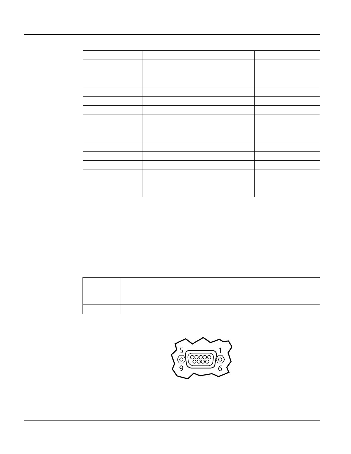
Supported Interfaces QTERM-G55 Terminal
DB15f Pin Wire Color Twisted Pairs
1 Red with Black Stripe
2 White with Red Stripe Pair #3
3 W hite with Green Stripe Pair #3
4Blue
5 Yellow
6RedPair #2
7BlackPair #1
8Gray
9Brown
10 Drain
11 Orange
12 Green with Black Stripe
13 Green Pair #2
No 14 White Pair #1
15 Violet
3.2.2 Panel-mount Connector Interface
The panel-mount QTERM-G55 comes standard with one serial port with DB9f connector. The
serial port interface can be EIA-232, EIA-422, or EIA-485. A second serial port is a v ailable as
an option.
N
OTE
☞
The primary panel-mount and auxiliary serial ports are wired as Data Communications
Equipment (DCE).
EIA-232
EIA-422 permits operation at distances up to 2,000 meters
EIA-485 permits multiple terminals to be connected in a multi-drop chain
Figure 18 shows the panel-mount unit serial connector orientation.
with proper cables and grounding the terminal can communicate up to five
meters at a top speed of 115,200 bps
40
Figure 18
QTERM-G55 Panel-mount Serial Connector
Qlarity-Based Terminal Hardware
Page 53

QTERM-G55 Terminal Supported Interfaces
The following table shows the pinouts for each type of serial interface.
Pin 232 422 485
1 — Tx- RTx2Tx Tx+ RTx+
3Rx Rx+ —
4— — —
5 Ground Ground Ground
6— Rx- —
7CTS (in) —
8RTS (out) —
9Power Power Power
Power is supplied to the terminal through pin 9 and ground is supplied through p in 5 of the primary serial port connector. System ground is also connected to pin 5 of the secondary serial
port connector.
3.2.2.1 Optional Ethernet Port (Panel-mount)
The optional Ethernet port has a standard 10Base-T interface with an 8-pin (RJ-45) modular
jack connector and uses TCP/IP protocol.
The connector orientation and pinout table are shown in Figure 19.
QTERM-G55 Ethernet Port Pinouts
3.2.3 Optional Power-over-Ethernet Module
Figure 19
The optional Power-o ver-Ethernet module allows the user to provide power and communications to the QTERM-G55. The power can be pro vided from an IEEE 802.3af comp liant hub or
switch as well as from a standard power supply.
Qlarity-Based Terminal Hardware 41
Page 54

Supported Interfaces QTERM-G55 Terminal
3.2.3.1 Power Requirements
The optimal power supplied to the QTERM-G55 through the PoE port is 48 The analog-resistive touch screen covers the full viewable area of the display. The touch screen is the primary
mechanism for user input.
For communications, the QTERM-G72 comes equipped with two serial ports. The primary
serial port is software-configurable to EIA-232 (with RTS/CTS flow control), EIA-422 or
EIA-485 interfaces. The secondary serial port uses an EIA-232 interface with hardware
(RTS/CTS) or software flow control. The product also includes one 10/100Base-T Ethernet
(RJ45 connector) and one USB 2.0 full speed port (mass storage devices only). The I/O connectors are accessible at the terminal back panel and are angled towards the bottom of the terminal to facilitate mounting in shallow panels areas.
Other key standard features include a speaker, which has programmable pitch and duration,
and an audio decoder for playing audio wav e fi les. The terminal also includes a battery-backed
real-time clock and a hardware watchdog timer.
The terminal stores the firmware and the user application in a compressed format in flash
memory and then transfers them to RAM memory when the terminal is powered on. The terminal is equipped with four megabytes of flash memory and 32 megabytes of RAM memory.
The QTERM-G72 electronics are packaged in a rugged and attractive black thermoplastic
NEMA-4X housing which accommodates the same panel cutout as our QTERM-G70 terminal. Optional pad printing of the front bezel with logo/name or graphics is available as an
option.
The QTERM-G72 terminal requires a DC power source in a range of 10 to 32 VDC. This
power can be supplied either via the main DB9 serial connector or the 3-pin power terminal
strip (which includes power input, return and chassis ground).
DC, although the unit will operate with a power input as low as 36 VDC, or as high as 57 VDC
(see IEEE 802.3af specification). The power required to operate the terminal with out any
additional options is listed below.
3.2.3.2 Pinouts (Panel-mount)
In accordance with the PoE standard (IEEE 802.3af), the PoE port is insensitive to polarity of
the power supply and can receive power in either mode A (superimposed on the transmit and
receive twisted pair conductors) or mode B (using the additional tw isted pair conductors). This
Current Consumption
Terminal 48VDC
G55 STN Idle 70 mA
Active Add +10 mA
42
Qlarity-Based Terminal Hardware
Page 55

QTERM-G55 Terminal Terminal Components
yields four possible ways to apply power to the PoE port as shown in the following table. The
table also shows the conductor assignment for the transmit and receive lines as a reference.
Port Pin Assignment
Conductor Data
1Tx+
2Tx3Rx+
4PoE V+
5
6Rx7PoE V8
N
OTE
☞
The pinouts for the PoE option on the handheld terminal are shown in section 3.2.1, “Hand-
held Connector Interface.”
3.3 Terminal Components
3.3.1 Display
The standard QTERM-G55 features a QVGA, 320x240 pixel, LCD transflective FSTN, grayscale (16 shades) display. It uses a light emitting diode (LED) backlight. The LED provides
reasonable contrast at low power consumption and easy readability. The contrast is software-controlled and compensated for temperature. The transflectiv e display provides e xcellent
contrast in sunlight and high ambient light environments. Refer to Figure 20.
Figure 20
QTERM-G55 Display
Qlarity-Based Terminal Hardware 43
Page 56

Terminal Components QTERM-G55 Terminal
The QTERM-G55 may be optionally equipped with a color QVGA, 320x240 pixel,
active-matrix TFT LCD (256 colors). It also uses a light emitting diode (LED) backlight, wit h
a typical brightness of 200 nits.
3.3.2 Keypad
User input occurs through a rugged 24-key or 40-key membrane keypad with steel snap
domes. The top row of keys a commonly used as soft keys to navigate through a set of changing menus at the bottom of the display. The standard keypad comes with four or five LEDs
under the soft keys that can be used as status or alarm indicators. Power and shift buttons with
LEDs are included on both keypad configurations. The power button puts the terminal into a
sleep mode for low power consumption and provides instant-on function with no loss of program state.
The 40-key keypad allows for function / softkeys, eight-way directional control and numeric
entry in the unshifted mode and alphanumeric data entry in the shifted mode. Keys can perform alternate functions when the shift key is enabled. The power and shift functions can be
enabled or disabled in software.
3.3.3 Speaker
The keypad legend can be customized with your logo/name and custom keys.
A speaker is built into the QTERM-G55 terminal and faces to the back of the unit. Audio can
be linked to events or actions (e.g., screen press, timer, etc.). Pitch and duration of a sound are
controlled by API functions called from the user application. Refer to “Controlling the
Speaker” section in the Qlarity-based Terminal Progr ammer's Refer ence Manual. Newer mod-
els also include a course volume control that is accessible via software.
Optionally, an audio (.wav) decoder can be added to the QTERM-G55 to allow the speaker to
play audio files. The audio decoder supports wave files meeting the following criteria:
• Sample rate of 8 kHz, 11.025 kHz, 16 kHz or 22.050 kHz
• Resolution of 8 or 16 bits per sample.
The audio decoder circuit amplifies the signal to 0.5 W rms at the speaker .
44
Qlarity-Based Terminal Hardware
Page 57

QTERM-G55 Terminal Installing to NEMA-4 Specifications
3.3.4 Real-Time Clock
The QTERM-G55 terminal can be optionally equipped with a battery-backed, real-time clock.
The real-time clock can be used to time/date stamp messages or for timed polling and program
execution.
WARNING
There may be danger of leakage if the battery is incorrectly replaced, creating a potential
health hazard. Replace the battery only with the same (CR1220) or equivalent type as recommended by the manufacturer. Dispose of used batteries according to the manufacturer’s
instructions.
3.3.5 System Memory
The QTERM-G55 terminal stores the firmware and user applications in a compressed format
in flash memory and then transfers them to RAM memory when the terminal is powered on.
Two megabytes of flash memory and sixteen megabytes of RAM memory are standard.
For information on using resources efficiently to conserve memory when creating a user application, refer to “Edit Resources” section in the Qlarity Foundry User Guide.
For information on downloading new f irmw are, downloading a user application, and determining the size of a user application, refer to the Qlarity Foundry User Guide.
3.4 Installing to NEMA-4 Specifications
A QTERM-G55 terminal uses a rugged ABS poly carbonate with rubber overmold case
designed to mount into a panel. When properly installed in a NEMA-4 rated panel, the
QTERM-G55 meets all NEMA-4 specifications including hose-down, icing, and salt spray.
A QTERM-G55 terminal can be installed in either a landscape or portrait orientation. When
installing a terminal, you generally take the following steps.
• Decide whether you want to mount and use the terminal in a portrait or landscape orienta-
tion. “Portrait” means that the longest dimension is vertical; “landscape” means that the
longest dimension is horizontal.
• Cut a hole in the panel. See section 3.4.1, “Cutout for Panel Mount Configuration” for spec-
ifications.
• Install the QTERM-G55 terminal in the panel. See section 3.4.2, “Installing the Panel
Mount Terminal” for instructions.
• Connect cables to the terminal. Verify that the thumb screws are tight or the locks snapped
into place for each cable used.
• Apply DC power to the QTERM-G55 terminal. See section 3.4.3, “Applying Power” for
information.
Qlarity-Based Terminal Hardware 45
Page 58

Installing to NEMA-4 Specifications QTERM-G55 Terminal
3.4.1 Cutout for Panel Mount Configuration
The QTERM-G55 terminal can be mounted in panels from 0 to 7 mm thick. No screw holes
need to be drilled to install the terminal in the panel.
Make a rectangular hole in the panel using the following dimensions.
Horizontal: 117.2 ± 1 mm
Vertical: 212.6 ± 1 mm
File any rough edges smooth, especially on the face of the panel.
Figure 21 is a diagram of the panel mount cutout.
3.4.2 Installing the Panel Mount Terminal
46
NOTE
☞
Use of an anti-static strap is recommended when performing installation and maintenance.
Take the following steps to install the terminal. Refer to the illustrations on the next page.
1. Verify that the panel surface around the cutout is clean and free of rough edges. A gasket
built into the terminal will seal against this surface. Dirt or imperfections on the panel may
prevent a proper seal.
2. Place the terminal into the panel cutout and verify that the terminal is oriented correctly.
Figure 21
QTERM-G55 Panel Mount Cutout
Qlarity-Based Terminal Hardware
Page 59

QTERM-G55 Terminal Installing to NEMA-4 Specifications
3. On the back of the panel, place the terminal mount in bracket against the back of the terminal, and align it with the back panel.
4. Fasten the six screws (supplied with the terminal).
3.4.3 Applying Power
Power is supplied to the QTERM-G55 terminal via the 12-pin round connector (handheld) or
the primary serial port connector (panel-mount). Refer to section 3.2.1, “Handheld Connector
Interface” or section 3.2.2, “Panel-mount Connector Interface” for the pin assignments for
power and ground. DC power must be in the range of 8 to 32 volts (the current will vary
depending on the input voltage; see following table).
CAUTION
QTERM-G55 power must come from an SELV (Safety Extra Low Voltage) power source
and should have a current limit on its output of 5 Amperes. It must provide a minimum of 8
volts DC power and be limited to a maximum of 32 volts DC. Limiting may be inherent to
the supply or may be provided by supplementary overcurrent devices. If the QTERM-G55
does not respond or exhibits abnormal behavior on power up, disconnect power and contact
Beijer Electronics for technical support.
Current Consumption
Terminal 12 VDC 24 VDC PoE
Standard unit (grayscale, no options), idle 120 mA 70 mA 70 mA
Standard TFT unit (color), idle 170 mA 92 mA 90 mA
Standard unit, active add 90 mA add 40 mA add 10 mA
Standard TFT unit (TFT, no options), active add 90 mA add 40 mA add 20 mA
With Ethernet option and connection add 50 mA add 20 mA N/A
Standard unit, sleep mode 12 mA 7 mA 30 mA
Standard TFT unit, sleep mode 60 mA 35 mA 50 mA
3.4.4 Powering On the Terminal for the First Time
When you connect power to the QTERM-G55 terminal, it automatically loads the application
saved in flash memory into RAM memory and executes the application. If no application is
present, the terminal display may be blank but the backlighting verifies it is powered on.
When you power on the terminal for the first time, a demo application (or a custom application
designed for your company) loads. The demo application will help you verify that the terminal
is operating properly. Follow the on-screen prompts or any documentation accompanying the
program to guide you through tests or demonstrations designed to verify terminal operation.
Qlarity-Based Terminal Hardware 47
Page 60

Installing to NEMA-4 Specifications QTERM-G55 Terminal
Once you have v erified that the terminal is functioning properly, refer to Chapter 8, “Power On
Setup” for information on configuring your terminal. The Power On Setup utility includes
functions to do the following:
• Change orientation of the terminal (portrait or landscape)
• Download a new user application to the terminal
• Select the application mode
• Set up communications settings for the terminal
• Adjust display contrast or backlight
• Enter network (Ethernet) settings
• Enter/change password (if used)
• Set the real-time clock (if available)
48
Qlarity-Based Terminal Hardware
Page 61

CHAPTER 4
QTERM-G56 TERMINAL
4.1 Product Description
The QTERM-G56 is a rugged handheld color LCD graphic terminal with object-based programming. It features a robust list of industrial-grade hardware features and options, including
wired Ethernet.
The QTERM-G56 features a QVGA (320x240 pixel) transflective color TFT liquid crystal display (LCD, 256 colors) with integrated 4-wire analog-resistive touch screen. The display
includes a light emitting diode (LED) backlight with software-controlled dimming capability.
The LED provides reasonable contrast at low power consumption and easy readability.
transflective displa y pro vides ex cellent contrast in sunlig ht and high ambient light environments.
The QTERM-G56 is equipped with one serial “multiprotocol port,” which is a software-selectable EIA-232/422/485 serial port. The multiprotocol port 485 interface supports software-selectable AC terminations and a fail-safe network, which holds the 485 signal lines in a
known state when no transceiver is transmitting. The terminal may optionally include one
wired 10/100Base-T Ethernet interface. The QTERM-G56 (without the Ethernet option)
includes one EIA-232 serial port with RTS/CTS flow control.
The
User input occurs through the touch screen and a rugged 24-key or 40-key membrane keypad
with steel snap domes. The top row of keys are commonly used as soft keys to navigate
through a set of changing menus at the bottom of the display . The standard ke ypad comes with
four or fiv e LEDs under the soft k e ys that can be used as status or alarm indi cators. Power and
shift buttons with LEDs are included on both keyp ad configurations . The power b utton enables
and disables the internal power supply for low power consumption. The terminal may optionally include a software-enabled electroluminescent keypad backlight.
The standard 40-key keypad legend allows for function/soft keys, eight-way directional control and numeric entry in the unshifted mode and alphanumeric data entry in the shifted mode.
Keys can perform alternate functions when the shift key is enabled. Both the power and shift
functions can be enabled or disabled in software. The keypad legend can be customized with
your logo/name and custom keys.
The QTERM-G56 terminal stores the firmware and the user application in a compressed format in flash memory and then transfers them to RAM memory when the terminal is powered
on. The terminal is equipped with 4 MB of NOR flash memory (for firmware and application),
32 MB of RAM memory , and 256 MB of internal NAND flash memory for mass storage. The
NAND memory is accessible as a FA T-formatted file system both from the application and via
the USB device interface (although not simultaneously).
The QTERM-G56 terminal includes a switching power supply with a wide input voltage range
of 8 to 32 VDC. Typically, power is supplied through the 12-pin circular push-lock connector
or integral cable. The unit may also be powered from a 5 volt USB host port.
Qlarity-Based Terminal Hardware 49
Page 62

Product Description QTERM-G56 Terminal
Other features include a speaker with software-controlled note pitch, duration, and volume.
The terminal may optionally include an audio decoder for .wav f ile playback. All units feature
a real-time clock with one second resolution and battery backup po wer. The terminal may
optionally include an integral cable. T erminal s with the inte gral cable may optionally include a
2-pole, normally closed emergency stop switch.
4.1.1 Specifications
The following tables contain the technical specifications for the QTERM-G56.
TERMINAL DISPLAY
Active Matrix Color TFT 256 colors transflective
Pixels 320 x 240
Pixel Pitch 0.2235 mm
Lighting Light emitting diode brightness is software-controllable
Backlight Brightness 200 cd/m2 typical
Contrast
Analog-resistive operation
Transparent touch area over viewable display
24 or 40 keys
Steel snap domes in membrane
Lighted keypad with electroluminescent lighting (optional)
Optional emergency stop switch (2-pole, normally closed; a vailable with integral cable only)
Serial
Serial (second port, without
Ethernet option)
Baud Rates 600 – 115200 bps
Flow control
Transmissive: 150:1 typical
Reflective: 15:1 typical
TOUCH SCREEN
KEYPAD
INTERFACE
Software-selectable EIA-232/422/485 serial port with selectable 485 AC terminations and fail-safe network
EIA-232 serial port with hardware (RTS/CTS) or software
(XON/XOFF) handshaking (RTS/CTS not available with integral cable option)
None
XON/XOFF (software)
RTS/CTS (hardware)
50
Qlarity-Based Terminal Hardware
Page 63
QTERM-G56 Terminal Product Description
INTERFACE (continued)
7 or 8 data bits
Data formats
Connector
Ethernet (optional) 10/100Base-T with support for TCP/IP
1 or 2 stop bits
Even, odd, or no parity
(Development tools support only 8 data bits)
12-pin round (Hirose HR30-8R-12SC)
Integral cable with DB15f (optional)
USB device
Standard
Software programmable pitch and duration
Audio (.wav) decoder (optional)
Standard
Housing ABS/polycarbonate case with molded rubber boot
Size 129 x 234 x 43 mm
Mass 510 g
Processor ARM926EJ-S 192 Mhz
4 MB flash and 32MB SDRAM
256 MB NAND flash accessible as FAT-formatted file system
Independent processor-based real-time clock with battery backup, 1 second
resolution
USB 2.0 full speed (12 megabits/second) for access to internal
NAND flash file system
MEMORY
SPEAKER
REAL-TIME CLOCK
PHYSICAL
ENVIRONMENTAL
Sealing
Temperature
Humidity 0 to 95%, non-condensing
Vibration 5 to 2000 Hz, 4 g RMS
Shock 20 g, 6 ms, 6 axis
8 to 32 VDC (See section 4.3.7 for current consumption)
5 VDC USB Host Port
Qlarity-Based Terminal Hardware 51
NEMA-12 (Standard)
NEMA-4 (optional)
Operating: -20 to 60 °C
Storage: -40 to 85 °C
POWER
Page 64

Supported Interfaces QTERM-G56 Terminal
SOFTWARE
Programming language Qlarity (object-based)
Design environment Qlarity Foundry (Windows)
Command line compiler Qlarify (Win32 or Linux)
CUSTOMIZING
Keypad legend Customize with logo/name or graphics
CERTIFICATION
FCC Part 15, Class A
CE Certification
4.2 Supported Interfaces
4.2.1 Connector Interface
The QTERM-G56 handheld terminal comes with one serial multiprotocol port through a
12-pin round connector (Hirose HR30-8R-12SC) or integral cable with strain relief, terminated with a DB15f connector. The multiprotocol port interface is software-selectable to
EIA-232, EIA-422 or EIA-485. The EIA-485 interface includes AC terminations and a
fail-safe network, each of which can be set in software. Units without the Ethernet option also
include one serial EIA-232 auxiliary port.
EIA-232
EIA-422 permits operation at distances up to 2,000 meters
EIA-485 permits multiple terminals to be connected in a multi-drop chain
Figure 22 shows the handheld unit connector orientation.
with proper cables and grounding the terminal can communicate up to five
meters at a top speed of 115,200 bps
52
Figure 22
QTERM-G56 Handheld Connector
Qlarity-Based Terminal Hardware
Page 65

QTERM-G56 Terminal Supported Interfaces
4.2.1.1 Power and USB Device Interfaces
The following table shows the pinout for the power and USB device interfaces.
Pin
1 8 - 32 VDC 4.5 - 5.5 VDC
2 Ground Ground
11 N/A USB D+
12 N/A USB D-
Regulated
(standard)
4.2.1.2 Serial Multiprotocol Port Interface
The following table shows the connector pinout for the selected type of serial interface on the
multiprotocol port.
Pin EIA-232 EIA-422 EIA-485
3 Tx Tx- RTx4 RTS (out) Tx+ RTx+
5 Rx Rx+ No signal
6 CTS (in) Rx- No signal
4.2.1.3 Additional Serial Interface (without Ethernet option)
PC USB
Host Port
The following table shows the connector pinout for the G56L EIA-232 serial interface.
Pin EIA-232
7Tx
8RTS (out)
9Rx
10 CTS (in)
4.2.1.4 Network Interface (with Ethernet option)
The following table shows the cable pinout for the 10/100Base-T network interface.
Pin Ethernet
7Tx+
8Tx9Rx+
10 Rx-
Qlarity-Based Terminal Hardware 53
Page 66

Supported Interfaces QTERM-G56 Terminal
4.2.1.5 Accessory Cable Wire Color Code and Demo Cable Pinout
The following table shows the wire color code for the 12-pin roun d connector to unterminated
(“blank”) accessory cable and the pinout to the demo cable, which terminates in a 15-pin
female D subminiature connector (DB15f); see section 4.2.2, “Integral Cable” for a diagram
showing the DB15f orientation. The cable contains fifteen conductors; however, only twelve
conductors are connected to pins on the round connector and DB15f. Ten of the fifteen conductors in the cable are wired as 100 ohm twisted pairs, as shown in the table. One of the fifteen conductors is a non-insulated drain wire that is shorted to the foil shielding in the cable.
This drain wire is not connected to the round connector or DB15f connector.
Round
Connector Pin
1Brown –9
2 Red with Black Stripe – 1
3 Black Pair #1 4
4 White Pair #1 5
5 Red Pair #2 10
6 Green Pair #2 11
7 White with Red Stripe Pair #3 7
8 White with Green Stripe Pair #3 14
9 Yellow Pair #4 6
10 Blue Pair #4 13
11 Orange P air #5 2
12 Gray Pair #5 3
No Connect Violet – 8
No Connect Green with Black Stripe – 12
No Connect Drain – 15
Wire Color Twisted Pairs
Demo Cable
DB15f Pin
4.2.2 Integral Cable
54
The QTERM-G56 can be optionally equipped with an integral cable (instead of the 12-pin
round connector). This cable is terminated with a DB15f connector. Figure 23 shows the integral cable connector orientation.
Qlarity-Based Terminal Hardware
Page 67

QTERM-G56 Terminal Supported Interfaces
Figure 23
QTERM-G56 Integral Cable Connector
4.2.2.1 Power and USB Device Interfaces with Integral Cable
The following table shows the pinout for the power and USB device interfaces when the integral cable option is selected.
DB15f Pin Regulated (standard) 5 Volt USB Host
9 8 - 32 VDC 4.5 - 5.5 VDC
1 Ground Ground
2 N/A USB D+
3 N/A USB D-
4.2.2.2 Serial Interface with Integral Cable
The following table shows the pinout for the selected typed of serial interface on the multiprotocol port.
DB15f Pin EIA-232 EIA-422 EIA-485
4Tx Tx- RTx-
5 RTS (out) Tx+ RTx+
10 Rx Rx+ No connect
11 CTS (in) Rx- No connect
4.2.2.3 Additional Serial Interface with Integral Cable (without Ethernet option)
The following table shows the pinout for the EIA-232 serial interface with integral cable.
Pin EIA-232
7Tx
14 RTS (out)
6Rx
13 CTS (in)
Qlarity-Based Terminal Hardware 55
Page 68

Supported Interfaces QTERM-G56 Terminal
4.2.2.4 Network Interface with Integral Cable (with Ethernet option)
The following table shows the pinout for the 10/100Base-T network interface.
DB15f Pin Ethernet
7Tx+
14 Tx-
6Rx+
13 Rx-
4.2.2.5 E-stop Option with Integral Cable
If the terminal is equipped with the E-stop option (which requires the integral cable), the
DB15f pinout changes to accommodate the switch signals, as shown below.
4.2.2.6 Power and USB Device Interfaces with E-stop Option and Integral Cable
The following table shows the pinout for the power and USB device interfaces when the
E-stop option and integral cable are selected.
DB15f Pin Regulated (standard) 5 Volt USB Host
9 8 - 32 VDC 4.5 - 5.5 VDC
1 Ground Ground
2 N/A USB D+
3 N/A USB D-
4.2.2.7 Serial Interface with E-Stop Option and Integral Cable (without Ethernet option)
The following table shows the pinout for the selected typed of serial interface on the multiprotocol port with integral cable and E-stop option.
DB15f EIA-232 EIA-422 EIA-485
4TxTx-Rtx14 RTS (out) Tx+ Rtx+
10 Rx Rx+ No connect
13 CTS (in) Rx- No connect
56
Qlarity-Based Terminal Hardware
Page 69

QTERM-G56 Terminal Supported Interfaces
4.2.2.8 Additional Serial Interface with E-Stop Option and Integral Cable (without Ethernet option)
The following table shows the pinout for the EIA-232 serial interface with integral cable and
E-stop option.
Pin EIA-232
7Tx
6Rx
4.2.2.9 Network Interface with E-Stop Option and Integral Cable (with Ethernet option)
The following table shows the pinout for the 10/100Base-T network interface with integral
cable and E-stop option.
DB15f Pin Ethernet
7Tx+
14 Tx-
6Rx+
13 Rx-
4.2.2.10Serial Interface with E-stop Option and Integral Cable (with Ethernet option)
The following table shows the pinout for each type of serial or network interface.
DB15f Pin EIA-232
4Tx
10 Rx
N
OTE
☞
Due to pin constraints, the EIA-422 and EIA-485 multiprotocol serial port interfaces are not
available with the E-stop/integral cable/Ethernet options, and the EIA-232 interface does not
have RTS/CTS flow control. The terminal should be set in software or Power On Setup to
EIA-232 only with no hardware handshaking
4.2.2.11E-stop Switch Interface with Integral Cable
The following table shows the integral cabl e pino ut for the two-pole normally closed E-stop
switch. The conductors for each pole (Pole 1 and Pole 2) of the switch are shorted until the
switch is activated. After activation, each pole is an open circuit until the switch is reset.
DB15f Pin E-stop Switch
5Pole 1
8Pole 1
11 Pole 2
12 Pole 2
Qlarity-Based Terminal Hardware 57
Page 70

Terminal Components QTERM-G56 Terminal
4.2.2.12Integral Cable Wire Color Code
The following table shows the wire color code for the DB15f connector on the integral cable;
this information is provided to facilitate removal of the DB15f if desired. Ten of the fifteen
conductors in the cable are wired as 100 ohm twisted pairs, as shown in the table. One of the
fifteen conductors is a non-insulated drain wire that is shorted to the foil shielding in the cable.
DB15f Pin Wire Color Twisted Pairs
1 Red with Black Stripe –
2Orange Pair #5
3 Gray Pair #5
4Black Pair #1
5 White Pair #1
6 Yellow Pair #4
7 White with Red Stripe Pair #3
8Violet –
9Brown –
10 Red Pair #2
11 Green Pair #2
12 Green with Black Stripe –
13 Blue Pair #4
14 Whit e with Green Stripe Pair #3
15 Violet –
4.3 Terminal Components
4.3.1 Display
The standard QTERM-G56 features a QVGA (320x240 pixel) transflective color TFT LCD
(256 colors). The display includes a light emitting diode (LED) backlight with software-controlled dimming capability . The LED backlight pro vides reasonable contrast at lo w po wer consumption and easy readability . The transflecti v e display provides e xcellent contrast in sunlight
and high ambient light environments. Refer to Figure 24.
58
Qlarity-Based Terminal Hardware
Page 71

QTERM-G56 Terminal Terminal Components
Figure 24
QTERM-G56 Display
4.3.2 Touch Screen
The QTERM-G56 touch screen provides user input through an y number of touch keys located
on the display. Touch keys can be defined in your user applications at any location on the display and may be any size. Most visible objects in the Qlarity Object libraries are inherently
touch-sensitive. The touch screen functionality can also be enabled or disabled in software
(either in the user application or via the Power On Setup utility).
4.3.3 Keypad
4.3.4 Speaker
User input also occurs through a rugged 24-key or 40-key membrane keypad with steel snap
domes. The top row of keys are commonly used as soft keys to navigate through a set of
changing menus at the bottom of the display. The standard keypad comes with four or five
LEDs under the soft keys that can be used as status or alarm indicators. Power and shift buttons with LEDs are included on both keypad configurations. The power button enables and
disables the internal power supply for true shutdown.
The standard 40-key keypad legend allows for function / soft keys, eight-way directional control and numeric entry in the unshifted mode and alphanumeric data entry in the shifted mode.
Keys can perform alternate functions when the shift key is enabled. The power and shift functions can be enabled or disabled in software.
The keypad legend can be customized with your logo/name and custom keys.
A speaker is built into the QTERM-G56 terminal and faces to the back of the unit. Audio can
be linked to events or actions (e.g., key press, timer, etc.). Pitch and duration of a note are controlled by API functions called from the user application. Refer to the “Controlling the
Speaker” section in the Qlarity-based Terminal Programmer’s Reference Manual. Volume
control is also accessible via software.
Qlarity-Based Terminal Hardware 59
Page 72

Terminal Components QTERM-G56 Terminal
The terminal may optionally include an audio decoder that allows the terminal to play PCM
audio (.wav) files. The audio decoder supports wave files meeting the following criteria:
• Sample rate of 8 kHz, 11.025 kHz, 16 kHz or 22.050 kHz
• Resolution of 8 or 16 bits per sample.
4.3.5 Real-Time Clock
The QTERM-G56 terminal includes a battery-backed real- time clock. The real-tim e clock can
be used to time/date stamp messages or for timed polling and program execution.
WARNING
There may be danger of leakage if the battery is incorrectly replaced, creating a potential
health hazard. Replace the battery only with the same (CR2032) or equivalent type as recommended by the manufacturer. Dispose of used batteries according to the manufacturer’s
instructions.
4.3.6 System Memory
The QTERM-G56 terminal stores the firmware and user applications in a compressed format
in flash memory and then transfers them to RAM memory when the terminal is powered on.
Four MB of flash memory and 32 MB of RAM memory are standard.
For information on using resources efficiently to conserve memory when creating a user application, refer to the “Edit Resources” section in the Qlarity Foundry User Guide.
For information on downloading new f irmw are, downloading a user application, and determining the size of a user application, refer to the Qlarity Foundry User Guide.
The QTERM-G56 also includes 256 MB of internal NAND flash which is accessible as a
FAT-formatted file system both from the application and the USB device port (but not simultaneously). Refer to section 4.4.1 for information on accessing the internal flash memory using
the USB device port.
60
Qlarity-Based Terminal Hardware
Page 73

QTERM-G56 Terminal Powering On the Terminal for the First Time
4.3.7 Applying Power
Power is supplied to the QTERM-G56 terminal via the 12-pin round connector or integral
cable. DC power must be in the range of 8 to 32 volts (the current will vary depending on the
input voltage; see the following table).
CAUTION
QTERM-G56 power must come from an SELV (Safety Extra Low Voltage) power source
and should have a current limit on its output of 5 Amperes. It must provide a minimum of 8
volts DC power and be limited to a maximum of 32 volts DC. Limiting may be inherent to
the supply or may be provided by supplementary overcurrent devices. If the QTERM-G56
does not respond or exhibits abnormal behavior on power up, disconnect power and contact
Beijer Electronics for technical support.
Current Consumption
Terminal 12 VDC 24 VDC
Power off 2 mA 5 mA
Idle 75 mA 50 mA
Ethernet option, active 155 mA 90 mA
Ethernet option, idle 130 mA 80 mA
Active 200 mA 115 mA
EL Keypad Backlight add 10 mA add 6 mA
4.4 Powering On the Terminal for the First Time
When you connect power to the QTERM-G56 terminal, the unit will remain unpowered until
you press the power button on the keypad. The unit is turned on or off by pressing the power
button. When the unit is powered on, it automatically loads the application saved in flash
memory into RAM memory and executes the application. If no application is present, the
Application Loader banner should appear on the display.
When you power on the terminal for the f irst time, a demo application (or a special appli cation
custom designed for your company) automatically loads. The demo application will help you
verify that the terminal is operating properly. Follow the on-screen prompts or any documentation accompanying the program to guide you through tests or demonstrations designed to verify terminal operation.
Once you have v erified that the terminal is functioning properly, refer to Chapter 8, “Power On
Setup” for information on configuring your terminal. The Power On Setup utility includes
functions to do the following:
• Change orientation of the terminal display (portrait or landscape)
• Download a new user application to the terminal
Qlarity-Based Terminal Hardware 61
Page 74

Powering On the Terminal for the First Time QTERM-G56 Terminal
• Select the application mode
• Set up communications settings for the terminal
• Adjust display backlight
• Enter network (Ethernet) settings
• Enter/change password (if used)
• Set the real-time clock
• Set speaker volume
• Adjust settings for the keypad and keypad backlight (if available)
4.4.1 Accessing The Internal Mass Storage Via US B
The QTERM-G56 includes internal NAND flash for mass storage. This storage memory is
accessible from both the application and the USB device interface, where it appears as a
FAT-formatted file system to the USB host.
To access the internal mass storage via USB, connect the terminal to a PC or other USB host
using the QTERM-G56 Programming Cable accessory. The USB host will enumerate the terminal, which should appear as a removable disk mounted to the host’s file system. The file system may take several seconds to become available for viewing or modification. Files may be
stored or retrieved using file access software on the PC, as with any USB mass storage device.
Note that many operating systems recommend or require that a USB remov able disk be ejected
before it is removed. See the documentation for your PC operating system for more details.
62
Qlarity-Based Terminal Hardware
Page 75

CHAPTER 5
QTERM-G58 TERMINAL
5.1 Product Description
The QTERM-G58 is a rugged handheld color LCD graphic terminal with object-based programming. It features a robust list of industrial-grade hardware features and options, including
wireless (802.11b/g) Ethernet and battery power.
The QTERM-G58 features a QVGA (320x240 pixel) transflective color TFT liquid crystal display (LCD, 256 colors) with integrated 4-wire analog-resistive touch screen. The display
includes a light emitting diode (LED) backlight with software-controlled dimming capability.
The LED provides reasonable contrast at low power consumption and easy readability. The
transflective display provides excellent contrast in sunlight and high ambient light environments.
The QTERM-G58 is equipped with one serial “multiprotocol port,” which is a software-selectable EIA-232/422/485 serial port. The multiprotocol port 485 interface supports software-selectable AC terminations and a fail-safe network, which holds the 485 signal lines in a
known state when no transceiver is transmitting. The G58 also integrates an internal lithium-polymer battery pack for portable operation. The G58 may optionally include an
802.11b/g wireless Ethernet interface.
User input occurs through the touch screen and a rugged 24-key or 40-key membrane keypad
with steel snap domes. The top row of keys are commonly used as soft keys to navigate
through a set of changing menus at the bottom of the display . The standard ke ypad comes with
four or fiv e LEDs under the soft k e ys that can be used as status or alarm indi cators. Power and
shift buttons with LEDs are included on both keyp ad configurations . The power b utton enables
and disables the internal power supply for low power consumption (and extended battery life).
The terminal may optionally include a software-enabled electroluminescent keypad backlight.
The standard 40-key keypad legend allows for function / soft keys, eight-way directional control and numeric entry in the unshifted mode and alphanumeric data entry in the shifted mode.
Keys can perform alternate functions when the shift key is enabled. Both the power and shift
functions can be enabled or disabled in software.
The keypad legend can be customized with your logo/name and custom keys.
The QTERM-G58 terminal stores the firmware and the user application in a compressed format in flash memory and then transfers them to RAM memory when the terminal is powered
on. The G58 is equipped with 4 MB of NOR flash memory (for firmware and application), 32
MB of RAM memory, and 256 MB of internal NAND flash memory for mass storage. The
NAND memory is accessible as a FA T-formatted file system both from the application and via
the USB device interface (although not simultaneously).
Qlarity-Based Terminal Hardware 63
Page 76

Product Description QTERM-G58 Terminal
The QTERM-G58 terminal includes a switching power supply with a wide input voltage range
of 8 to 32 VDC. Typically, power is supplied through the 12-pin circular push-lock connector
or integral cable. The unit may also be powered from a 5 volt USB host port – in this case, the
optional 802.11b/g wireless Ethernet interface is not accessible due to USB power supply limitations.
Other features include a speaker with software-controlled note pitch, duration, and volume.
The terminal may optionally include an audio decoder for .wav f ile playback. All units feature
a real-time clock with one second resolution and battery backup power.
5.1.1 Specifications
The following tables contain the technical specifications for the QTERM-G58.
TERMINAL DISPLAY
Active Matrix Color TFT 256 colors transflective
Pixels 320 x 240
Pixel Pitch 0.2235 mm
Lighting Light emitting diode brightness is software-controllable
Backlight Brightness 200 cd/m2 typical
Contrast
Analog-resistive operation
Transparent touch area over viewable display
24 or 40 keys
Steel snap domes in membrane
Lighted keypad with electroluminescent lighting (optional)
Serial
Baud Rates 600 – 115200 bps
Flow control
Transmissive: 150:1 typical
Reflective: 15:1 typical
TOUCH SCREEN
KEYPAD
INTERFACE
Software-selectable EIA-232/422/485 serial port with selectable 485 AC terminations and fail-safe network
None
XON/XOFF (software)
RTS/CTS (hardware)
64
Qlarity-Based Terminal Hardware
Page 77

QTERM-G58 Terminal Product Description
INTERFACE (continued)
7 or 8 data bits
Data formats
Connector 12-pin round (Hirose HR30-8R-12SC)
Wireless Ethernet (optional)
USB device
Standard
Software programmable pitch and duration
Audio (.wav) decoder (optional)
4 MB flash and 32MB SDRAM
256 MB NAND flash accessible as FAT-formatted file system
1 or 2 stop bits
Even, odd, or no parity
(Development tools support only 8 data bits)
802.11b/g
Infrastructure or Ad Hoc mode
Encryption: 128-bit WEP, WPA, WPA2 (TKIP/AES)
Dual internal antennas for receive diversity
USB 2.0 full speed (12 megabits/second) for access to internal
NAND flash file system
MEMORY
SPEAKER
REAL-TIME CLOCK
Standard
Housing ABS/polycarbonate case with molded rubber boot
Size 129 x 234 x 50 mm
Mass 650 g
Processor ARM926EJ-S 192 Mhz
Sealing NEMA-4
Temperature
Humidity 0 to 95%, non-condensing
Vibration 5 to 2000 Hz, 4 g RMS
Shock 20 g, 6 ms, 6 axis
Independent processor-based real-time clock with battery backup, 1 second
resolution
PHYSICAL
ENVIRONMENTAL
Operating: -20 to 60 °C (-20 to 55 °C with Wireless Ethernet option)
Storage: -40 to 85 °C
Battery charge: 0 to 40 °C
Qlarity-Based Terminal Hardware 65
Page 78
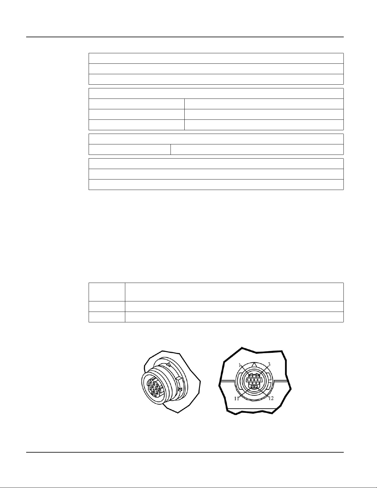
Supported Interfaces QTERM-G58 Terminal
POWER
8 to 32 VDC (See section 5.3.7 for current consumption)
5 VDC USB Host Port (Wireless Ethernet disabled)
SOFTWARE
Programming language Qlarity (object-based)
Design environment Qlarity Foundry (Windows)
Command line compiler Qlarify (Win32 or Linux)
CUSTOMIZING
Keypad legend Customize with logo/name or graphics
CERTIFICATION
FCC Part 15, Class A
CE Certification
5.2 Supported Interfaces
5.2.1 Connector Interface
The QTERM-G58 handheld terminal comes with one serial multiprotocol port through a
12-pin round connector (Hirose HR30-8R-12SC). The multiprotocol port interface is software-selectable to EIA-232, EIA-422 or EIA-485. The EIA-485 interface includes AC terminations and a fail-safe network, each of which can be set in software.
EIA-232
EIA-422 permits operation at distances up to 2,000 meters
EIA-485 permits multiple terminals to be connected in a multi-drop chain
Figure 25 shows the handheld unit connector orientation.
with proper cables and grounding the terminal can communicate up to five
meters at a top speed of 115,200 bps
66
Figure 25
QTERM-G58 Handheld Connector
Qlarity-Based Terminal Hardware
Page 79
QTERM-G58 Terminal Supported Interfaces
5.2.1.1 Power and USB Device Interfaces
The following table shows the pinout for the power and USB device interfaces.
Pin
1 8 - 32 VDC 4.5 - 5.5 VDC
2 Ground Ground
11 N/A USB D+
12 N/A USB D-
Regulated
(standard)
PC USB
Host Port
5.2.1.2 Serial Multiprotocol Port Interface
The following table shows the connector pinout for the selected type of serial interface on the
mulitport.
Pin EIA-232 EIA-422 EIA-485
3 Tx Tx- RTx4 RTS (out) Tx+ RTx+
5 Rx Rx+ No signal
6 CTS (in) Rx- No signal
5.2.1.3 Accessory Cable Wire Color Code and Demo Cable Pinout
The following table shows the wire color code for the 12-pin roun d connector to unterminated
(“blank”) accessory cable and the pinout to the demo cable, which terminates in a 15-pin
female D subminiature connector (DB15f). The cable contains fifteen conductors; however,
only twelve conductors are connected to pins on the round connector and DB15f. Ten of the
fifteen conductors in the cable are wired as 100 ohm twisted pairs, as shown in the table. One
of the fifteen conductors is a non-insulated drain wire that is shorted to the foil shielding in the
cable. This drain wire is not connected to the round connector or DB15f connector.
Round
Connector Pin
1Brown –9
2 Red with Black Stripe – 1
3 Black Pair #1 4
4 White Pair #1 5
5 Red Pair #2 10
6 Green Pair #2 11
7 White with Red Stripe Pair #3 7
8 White with Green Stripe Pair #3 14
Wire Color Twisted Pairs
Demo Cable
DB15f Pin
Qlarity-Based Terminal Hardware 67
Page 80

Terminal Components QTERM-G58 Terminal
Round
Connector Pin
9 Yellow Pair #4 6
10 Blue Pair #4 13
11 Orange P air #5 2
12 Gray Pair #5 3
No Connect Violet – 8
No Connect Green with Black Stripe – 12
No Connect Drain – 15
5.3 Terminal Components
5.3.1 Display
The standard QTERM-G58 features a QVGA (320x240 pixel) transflective color TFT LCD
(256 colors). The display includes a light emitting diode (LED) backlight with software-controlled dimming capability . The LED backlight pro vides reasonable contrast at lo w po wer consumption and easy readability . The transflecti v e display provides e xcellent contrast in sunlight
and high ambient light environments. Refer to Figure 26.
Wire Color Twisted Pairs
Demo Cable
DB15f Pin
5.3.2 Touch Screen
68
Figure 26
QTERM-G58 Display
The QTERM-G58 touch screen provides user input through an y number of touch keys located
on the display. Touch keys can be defined in your user applications at any location on the display and may be any size. Most visible objects in the Qlarity Object libraries are inherently
touch-sensitive. The touch screen functionality can also be enabled or disabled in software
(either in the user application or via the Power On Setup utility).
Qlarity-Based Terminal Hardware
Page 81

QTERM-G58 Terminal Terminal Components
5.3.3 Keypad
User input occurs through a rugged 24-key or 40-key membrane keypad with steel snap
domes. The top row of keys are commonly used as soft keys to navigate through a set of
changing menus at the bottom of the display. The standard keypad comes with four or five
LEDs under the soft keys that can be used as status or alarm indicators. Power and shift buttons with LEDs are included on both keypad configurations. The power button enables and
disables the internal power supply for true shutdown.
The standard 40-key keypad legend allows for function/soft keys, eight-way directional control and numeric entry in the unshifted mode and alphanumeric data entry in the shifted mode.
Keys can perform alternate functions when the shift key is enabled. The power and shift functions can be enabled or disabled in software.
The keypad legend can be customized with your logo/name and custom keys.
5.3.4 Speaker
A speaker is built into the QTERM-G58 terminal and faces to the back of the unit. Audio can
be linked to events or actions (e.g., key press, timer, etc.). Pitch and duration of a note are controlled by API functions called from the user application. Refer to the “Controlling the
Speaker” section in the Qlarity-based Terminal Programmer’s Reference Manual. Volume
control is also accessible via software.
The terminal may optionally include an audio decoder that allows it to play PCM audio (.w a v)
files. The audio decoder supports wave files meeting the following criteria:
• Sample rate of 8 kHz, 11.025 kHz, 16 kHz or 22.050 kHz
• Resolution of 8 or 16 bits per sample.
5.3.5 Real-Time Clock
The QTERM-G58 terminal includes a battery-backed real-t ime clock. The real-tim e clock can
be used to time/date stamp messages or for timed polling and program execution.
WARNING
There may be danger of leakage if the battery is incorrectly replaced, creating a potential
health hazard. Replace the battery only with the same (CR2032) or equivalent type as recommended by the manufacturer. Dispose of used batteries according to the manufacturer’s
instructions.
Qlarity-Based Terminal Hardware 69
Page 82

Terminal Components QTERM-G58 Terminal
5.3.6 System Memory
The QTERM-G58 terminal stores the firmware and user applications in a compressed format
in flash memory and then transfers them to RAM memory when the terminal is powered on.
Four MB of flash memory and 32 MB of RAM memory are standard.
For information on using resources efficiently to conserve memory when creating a user application, refer to the “Edit Resources” section in the Qlarity Foundry User Guide.
For information on downloading new f irmw are, downloading a user application, and determining the size of a user application, refer to the Qlarity Foundry User Guide.
The QTERM-G58 also includes 256 MB of internal NAND flash which is accessible as a
FAT-formatted file system both from the application and the USB device port (but not simultaneously). Refer to section 5.4.2 for information on accessing the internal flash memory using
the USB device port.
5.3.7 Applying Power
CAUTION
Power is supplied to the QTERM-G58 terminal via the 12-pin round connector or integral
cable. DC power must be in the range of 8 to 32 volts (the current will vary depending on the
input voltage; see the following table).
QTERM-G58 power must come from an SELV (Safety Extra Low Voltage) power source
and should have a current limit on its output of 5 Amperes. It must provide a minimum of 8
volts DC power and be limited to a maximum of 32 volts DC. Limiting may be inherent to
the supply or may be provided by supplementary overcurrent devices. If the QTERM-G58
does not respond or exhibits abnormal behavior on power up, disconnect power and contact
Beijer Electronics for technical support.
Current Consumption
Terminal 12 VDC 24 VDC Battery
Power off 2 mA 5 mA —
Idle 100 mA 65 mA 110 mA
Active 180 mA 100 mA 195 mA
Charging add 1200 mA max — —
Wireless Ethernet add 95 mA add 50 mA add 125 mA
EL Keypad Backlight add 10 mA add 6 mA add 13 mA
70
Qlarity-Based Terminal Hardware
Page 83

QTERM-G58 Terminal Powering On the Terminal for the First Time
5.4 Powering On the Terminal for the First Time
When you connect power to the QTERM-G58 terminal, the unit will remain unpowered until
you press the power button on the keypad. The unit is turned on or off by pressing the power
button. When the unit is powered on, it automatically loads the application saved in flash
memory into RAM memory and executes the application. If no application is present, the
Application Loader banner should appear on the display.
When you power on the terminal for the f irst time, a demo application (or a special appli cation
custom designed for your company) automatically loads. The demo application will help you
verify that the terminal is operating properly. Follow the on-screen prompts or any documentation accompanying the program to guide you through tests or demonstrations designed to verify terminal operation.
Once you have v erified that the terminal is functioning properly, refer to Chapter 8, “Power On
Setup” for information on configuring your terminal. The Power On Setup utility includes
functions to do the following:
• Change orientation of the terminal display (portrait or landscape)
• Download a new user application to the terminal
• Select the application mode
• Set up communications settings for the terminal
• Adjust display backlight
• Enter network (Wireless Ethernet) settings
• Enter/change password (if used)
• Set the real-time clock
• Set speaker volume
• Adjust settings for the keypad and keypad backlight (if available)
5.4.1 Powering and Charging the Battery Powered QTERM-G58
WARNING
The QTERM-G58 internal battery pack is not user-serviceable. Contact Beijer Electronics
for battery service or replacement.
DO NOT attempt to remove the battery pack from the terminal housing.
DO NOT puncture, bend, or place mechanical strain on the battery pack.
DO NOT attempt to charge the battery pack by any means other than the battery charge circuitry included on the QTERM-G58 circuit board.
The QTERM-G58 includes an internal rechargeable battery pack for untethered operation.
Press the power button on the keypad to power the terminal on and off. The Qlarity Object
Qlarity-Based Terminal Hardware 71
Page 84

Powering On the Terminal for the First Time QTERM-G58 Terminal
Library contains objects to indicate the current charge level of the battery, power source (external or battery), and other information. Refer to the Qlarity Foundry documentation for details.
Power (8 to 32 VDC) may be connected to the G58 terminal at any time. When external po wer
is detected, the terminal will use external power instead of the battery for operation.
The internal battery is charged by connecting a 12 VDC supply and ground to the power pins
of the terminal. Beijer Electronics offers charging cable accessories for standard AC mains
power (with optional international plug kit) and a vehicle cigarette lighter adapter . If the terminal is powered off at connection, the power and shift LEDs on the keypad will light, and the
display will show a battery charging icon. The icon and shift LED will flash during charging.
A continuously lit shift LED and static battery icon on the display indicate that charging is
complete. If the unit is powered on when the charge power supply is connected, the application
can detect and indicate charge status if desired.
5.4.2 Accessing The Internal Mass Storage Via US B
The QTERM-G58 includes internal NAND flash for mass storage. This storage memory is
accessible from both the application and the USB device interface, where it appears as a
FAT-formatted file system to the USB host.
N
OTE
☞
To access the internal mass storage via USB, connect the terminal to a PC or other USB host
using the QTERM-G58 Programming Cable accessory. The USB host will enumerate the terminal, which should appear as a removable disk mounted to the host’s file system. The file system may take several seconds to become available for viewing or modification. Files may be
stored or retrieved using file access software on the PC, as with any USB mass storage device.
Note that many operating systems recommend or require that a USB remov able disk be ejected
before it is removed. See the documentation for your PC operating system for more details.
The QTERM-G58 terminal is a self-powered USB device and draws ne gligible power from the
USB bus. Battery drain is comparable to untethered operation.
72
Qlarity-Based Terminal Hardware
Page 85

CHAPTER 6
QTERM-Z60 TERMINAL
6.1 Product Description
The QTERM-Z60 terminal is an econo mical graphic terminal with object-based programming.
T wo dif ferent models of the QTERM-Z60 e xist to suit any en vironment and b udget. In general,
the Z60/H version is NEMA-4 rated and has a user-selectable serial port while the Z60/L is
NEMA-12 rated, has one EIA-232 serial port and a slightly different display.
The QTERM-Z60 features a QVGA, 320x240 pixel, 256 co lor STN color LCD display. It uses
a cold-cathode fluorescent backlight (CCFL). The CCFL provides high contrast and easy readability and is replaceable. The contrast is software controlled and temperature compensated.
The analog-resistive touch screen covers the full viewable area of the display as well as the
pre-labeled legend underlay around the display.
The QTERM-Z60/H is equipped with one user-selectable serial port (EIA-232, EIA-422, or
EIA-485). The interface is selected using DIP switches. The QTERM-Z60/L is equipped with
one EIA-232 serial port.
A speaker, which has programmable pitch and duration, comes standard as does a 5 VDC 200
mA output from the interface connector to power external devices. An external reset signal
also comes standard to allow other devices to reset the QTERM-Z60.
The QTERM-Z60 terminal stores firmware and user applications in a compressed format in
flash memory and then transfers them to RAM memory when the terminal is powered on. The
terminal is equipped with two megabytes of flash memory and sixteen megabytes of RAM
memory.
The QTERM-Z60 terminal requires a DC power source ranging from 8 to 32 VDC. This
power is supplied via the main interface connector.
6.1.1 Specifications
The following tables contain the technical specifications for the QTERM-Z60.
Standard STN 256 colors
Pixels 320 x 240
Dot Pitch 0.36 mm
Contrast Software controlled, temperature compensated
TERMINAL DISPLAY
Qlarity-Based Terminal Hardware 73
Page 86

Product Description QTERM-Z60 Terminal
TERMINAL DISPLAY
Lighting Cold-cathode fluorescent, brightness is software-controllable
Backlight Brightness 200 nits typical
TOUCH SCREEN
Analog-resistive operation
Transparent touch area over viewable display
Labeled touch underlay area on each side of d isplay
INTERFACE
Z60/H EIA-232, -422 or -485 serial port
Z60/L E IA-232 serial port
Baud rates 600 – 115,200 bps
7 or 8 data bits
Data formats
Connector Molex 43045-1218
Mating Connector Mole x 43 025 -12 00
1 or 2 stop bits
Even, odd, or no parity
(PC To ols supports only 8 data bits)
Mating Connector Pins Molex 43 030 -00 01
MEMORY
Standard 2 Mbytes flash and 16 Mbytes SDRAM
SPEAKER
Standard Software programmable pitch and duration
PHYSICAL
Configuration Panel-mount
Housing
Size 215 x 161 x 50 mm
Weight 0.98 kg
Processor ARM 720T 77 MHz
QTERM-Z60/H Sealing NEMA-4 front panel
QTERM-Z60/L Sealing NEMA-12/13 front panel
Temperature
Glass-filled polyester, UL 94V-0 flame rating, accommodates panels
from 0 to 7 mm thick with standard screws
ENVIRONMENTAL
Operating: 0 to 50
Storage: -10 to 60 °C
°C
74
Humidity 0 to 95%, non-condensing
Qlarity-Based Terminal Hardware
Page 87

QTERM-Z60 Terminal Supported Interfaces
ENVIRONMENTAL
Vibration 5 to 5000 Hz, 4 g RMS
Shock 20 g, 3 ms, any axis
POWER
8 to 32 VDC (See section 6.4.3 for current consumption)
SOFTWARE
Programming language Qlarity (object-based)
Design environment Qlarity Foundry (Windows)
Command line compiler Qlarify (Win32 or Linux)
CERTIFICATION
FCC Part 15, Class A
CE Certification
6.2 Supported Interfaces
6.2.1 Serial Ports
The QTERM-Z60/H comes standard with one user-selectable serial port. The serial port interface can be selected via dip switc he s (EIA-2 32, EIA-422 or EIA-485). The QTERM-Z60/L is
equipped with one EIA-232 serial port.
N
OTE
☞
The serial port is wired as Data Communications Equipment (DCE)
The interface is selected using DIP switches. The following table shows the dip switch settings.
EIA-232 off off off off off on off off
EIA-422 off off off off on off off off
EIA-485onononononoffoffoff
Dip Switch Settings
12345678
Qlarity-Based Terminal Hardware 75
Page 88

Supported Interfaces QTERM-Z60 Terminal
Figure 27 shows the serial connector’s orientation.
Figure 27
QTERM-Z60 Serial Connector
EIA-232
EIA-422 permits operation at distances up to 2,000 meters
EIA-485 permits multiple terminals to be connected in a multi-drop chain
The following table shows the pinouts for the interface connector.
with proper cables and grounding the terminal can communicate up to
five meters at a top speed of 115,200 bps
Pin Function
1Power In
2 RS-232 TX (out)
3 EIA-422 TX+ (out)
4 EIA-422 RX+ (in), or EIA-485 RTX+
5 5 VDC output
6 No Connect
7Ground
8 RS-232 RX (in)
9 EIA-422 TX- (out)
10 EIA-422 RX- (in), or EIA-485 RTX11 External Reset (in)
12 No Connect
6.2.2 Five Volt Power Supply Output
Pin 5 of the interface connector is a 5 VDC power supply and can supply up to 200 mA current
to a serial peripheral device (such as a barcode reader). The ground return for the supply is on
pin 7 of the interface connector.
76
Qlarity-Based Terminal Hardware
Page 89

QTERM-Z60 Terminal Terminal Components
6.2.3 External Reset Input
Pin 11 of the interface connector is a reset signal compatible with 5 VDC and 3.3 VDC logic
signals. By applying a 3.3 VDC or 5 VDC pulse to this input, the terminal will perform a complete hardware reset.
6.3 Terminal Components
6.3.1 Touch Screen
The QTERM-Z60 touch screen provides user input through any numb er of touch keys located
on or around the display. The standard key legend shown in Figure 28 provides areas for five
soft keys down each side of the d isp lay. A custom legend underlay can be ordered to personalize the terminal for your application for shipments of over one hundred.
Figure 28
QTERM-Z60 Display
Touch keys can also be defined in your user applications at any location on or around the display. Touch keys may be any size.
6.3.2 Speaker
A speaker is built into the QTERM-Z60 terminal and faces to the back of the unit. Audio can
be linked to events or actions (e.g., screen press, timer, etc.). Pitch and duration are controlled
by API functions called from the user application. Refer to the “Controlling the Speaker” section in the Qlarity-based Terminal Programmer's Reference Manual.
Qlarity-Based Terminal Hardware 77
Page 90

Installing to NEMA-4 Specifications QTERM-Z60 Terminal
6.3.3 System Memory
The QTERM-Z60 terminal stores the firmware and user applications in a compressed format
in flash memory and then transfers them to RAM memory when the terminal is powered on.
Two megabytes of flash memory and sixteen megabytes of RAM memory are standard.
For information on using resources efficiently to conserve memory when creating a user application, refer to the “Edit Resources” section in the Qlarity Foundry User Guide.
For information on downloading new f irmw are, downloading a user application, and determining the size of a user application, refer to the Qlarity Foundry User Guide.
6.4 Installing to NEMA-4 Specifications
A QTERM-Z60 terminal uses a rugged, glass-filled polyester (UL 94V-0) case designed to
mount into a panel. When properly installed in a NEMA-4 rated panel, the QTERM-Z60
meets all NEMA-4 specifications including hose-down, icing, and salt spray.
A QTERM-Z60 terminal can be installed in either a landscape or portrait orientation. When
installing a terminal, you generally take the following steps.
• Decide whether you want to mount and use the terminal in a portrait or landscape orienta-
tion. “Portrait” means that the longest dimension is vertical; “landscape” means that the
longest dimension is horizontal.
• Cut a hole in the panel See section 6.4.1, “Cutting Out the Panel” for specifications.
• Install the QTERM-Z60 terminal in the panel. See section 6.4.2, “Installing the Terminal”
for instructions.
• Connect cables to the terminal. Verify that the thumb screws are tight or the locks snapped
into place for each cable used.
Apply DC power to the QTERM-Z60 terminal See section 6.4.3, “Applying Power” for infor-
mation.
6.4.1 Cutting Out the Panel
The QTERM-Z60 terminal can be mounted in panels from 0 to 7 mm thick. No screw holes
need to be drilled to install the terminal in the panel.
78
Make a rectangular hole in the panel using the following dimensions.
Landscape Portrait
Horizontal: 199 ± 1 mm Horizontal: 145 ± 1 mm
Vertical: 145 ± 1 mm Vertical: 199 ± 1 mm
Qlarity-Based Terminal Hardware
Page 91
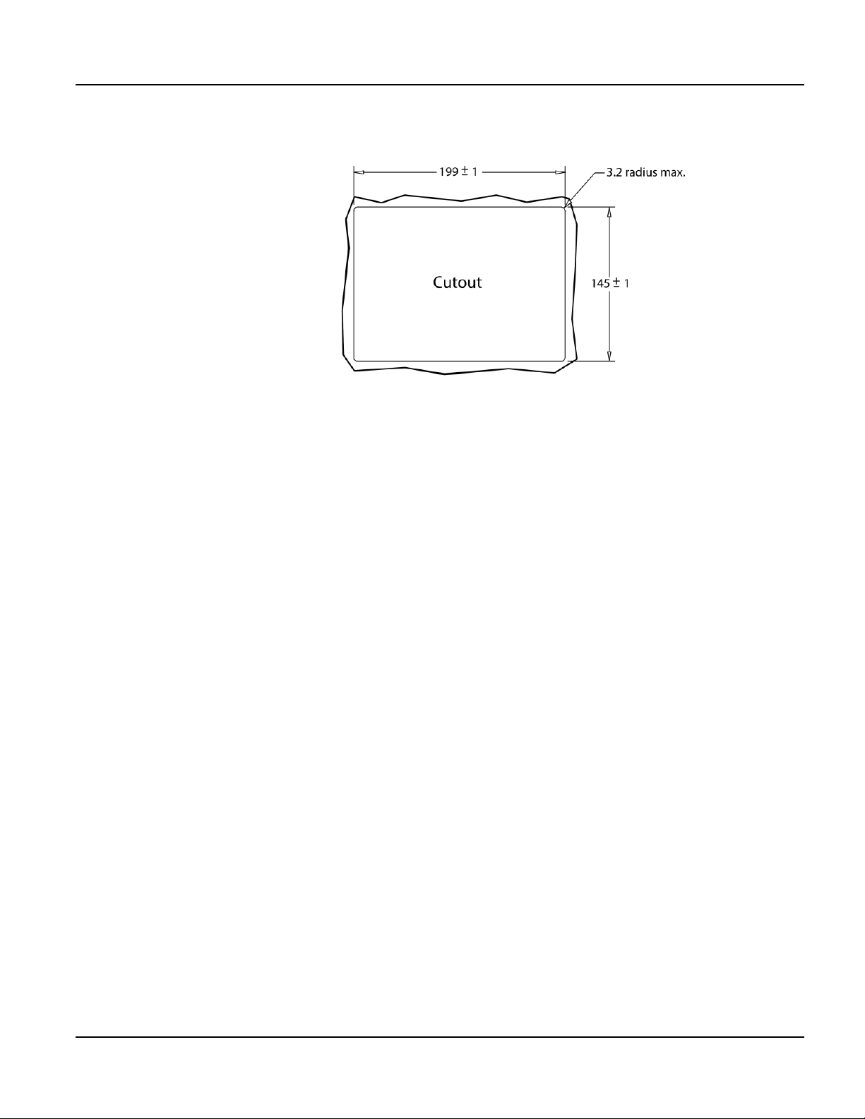
QTERM-Z60 Terminal Installing to NEMA-4 Specifications
Figure 29 is a diagram of the landscape cutout.
Figure 29
QTERM-Z60 Landscape Cutout
File any rough edges smooth, especially on the face of the panel.
6.4.2 Installing the Terminal
NOTE
☞
Use of an anti-static strap is recommended when performing installation and maintenance.
Take the following steps to install the terminal.
1. Verify that the panel surface around the cutout is clean and free of rough edges. A gasket
built into the terminal will seal against this surface. Dirt or imperfections on the panel may
prevent a proper seal.
2. Place the terminal into the panel cutout and verify that the terminal is oriented correctly.
The touch screen legend may indicate the orientation. If not, you can determine which side
should be at the top by the position of the serial port on the back panel as follows:
• Landscape
When looking at the front of the unit, the back panel serial port should be on the top of
the terminal.
• Portrait
When looking at the front of the unit, the back panel serial port should be on the right
side of the terminal.
Refer to Figure 30.
Qlarity-Based Terminal Hardware 79
Page 92

Installing to NEMA-4 Specifications QTERM-Z60 Terminal
Figure 30
QTERM-Z60 Front Panel Mount
3. On the back of the panel, place the terminal mounting bracket against the back of the terminal, and align it with the back panel. Refer to Figure 31.
Figure 31
QTERM-Z60 Back Panel Mount
4. Fasten the six screws (supplied with the terminal).
6.4.3 Applying Power
Power is supplied to the QTERM-Z60 terminal via the interface connector. Refer to
section 6.2.1, “Serial Ports” for the pin assignments for po wer and ground . DC power must be
80
Qlarity-Based Terminal Hardware
Page 93
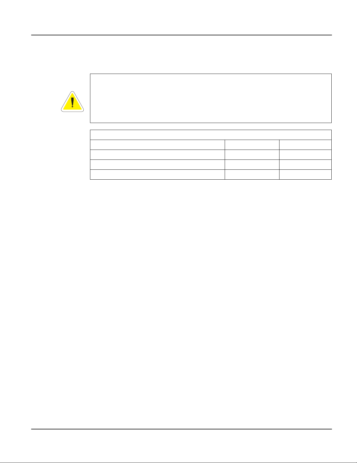
QTERM-Z60 Terminal Installing to NEMA-4 Specifications
in the range of 8 to 32 volts (the current will va ry depending on the input voltage; see t able that
follows.
CAUTION
QTERM-Z60 power must come from an SELV (Safety Extra Low Voltage) power source
and should have a current limit on its output of 5 Amperes. It must provide a minimum of 8
volts DC power and be limited to a maximum of 32 volts DC. Limiting may be inherent to
the supply or may be provided by supplementary overcurrent devices. If the QTERM-Z60
does not respond or exhibits abnormal behavior on power up, disconnect power and contact
Beijer Electronics for technical support.
QTERM-Z60/H / Z60/L Current Consumption
Terminal 12 VDC 24 VD C
Standard unit, idle 390 mA 200 mA
Standard unit, active add 40 mA add 20 mA
Standard unit, 200 mA load on 5 VDC supply add 140 mA add 70 mA
6.4.4 Powering On the Terminal for the First Time
When you connect power to the QTERM-Z60 terminal, it automatically loads the application
saved in flash memory into RAM memory and executes the application. If no application is
present, the terminal display may be blank but the backlighting verifies it is powered on.
When you power on the terminal for the f irst time, a demo application (or a special appli cation
custom designed for your company) loads. The demo application will help you verify that the
terminal is operating properly. Follow the on-screen prompts or any documentation accompanying the program to guide you through tests or demonstrations designed to verify terminal
operation.
Once you have v erified that the terminal is functioning properly, refer to Chapter 8, “Power On
Setup” for information on configuring your terminal. The Power On Setup utility includes
functions to do the following:
• Change orientation of the terminal (portrait or landscape)
• Download a new user application to the terminal
• Select the application mode
• Set up communications settings for the terminal
• Adjust display contrast or backlight
• Enter/change password (if used)
Qlarity-Based Terminal Hardware 81
Page 94

Installing to NEMA-4 Specifications QTERM-Z60 Terminal
Notes
82
Qlarity-Based Terminal Hardware
Page 95

CHAPTER 7
QTERM-G72 TERMINAL
7.1 Product Description
The QTERM-G72 human machine interface terminal is a large display Ethernet-enabled
graphic terminal with object-based programming. It features a robust list of industrial grade
hardware features and options.
The QTERM-G72 features a vivid WVGA (800 x 480), 177 mm (7"), color graphics
TFT-LCD display with 16 bit (65536) color (displayable colors are limited to 256 by Qlarity).
The display includes an LED backlight with software controllable dimming. W ith the incl uded
Ethernet 10/100Base-T interface and two serial ports, this terminal is ready to connect to
nearly any device.
The analog-resistive touch screen cov ers the full view able area of the display . The touch screen
is the primary mechanism for user input.
For communications, the QTERM-G72 comes equipped with two serial ports. The primary
serial port is software-configurable to EIA-232 (with RTS/CTS flow control), EIA-422, or
EIA-485 interfaces. The secondary serial port uses an EIA-232 interface with hardware
(RTS/CTS) or software flow control. The terminal also includes one 10/100Base-T Ethernet
(RJ45 connector) and one USB 2.0 full speed port (mass storage devices only). The I/O connectors are accessible at the terminal back panel and are angled towards the bottom of the terminal to facilitate mounting in shallow panel areas.
Other key standard features include a speaker, which has programmable pitch and duration,
and an audio decoder for playing audio wav e fi les. The terminal also includes a battery-backed
real-time clock and a hardware watchdog timer.
The terminal stores the firmware and the user application in a compressed format in flash
memory and then transfers them to RAM memory when the terminal is powered on. The terminal is equipped with four megabytes of flash memory and 32 megabytes of RAM memory.
The QTERM-G72 electronics are packaged in a rugged and attractive black thermoplastic
NEMA-4X housing that accommodates the same panel cutout as our QTERM-G70 terminal.
The QTERM-G72 terminal requires a DC power source in a range of 10 to 32 VDC. This
power can be supplied either via the main DB9 serial connector or the 3-pin power terminal
strip (which includes power input, return, and chassis ground).
Qlarity-Based Terminal Hardware 83
Page 96

Product Description QTERM-G72 Terminal
7.1.1 Specifications
The following tables contain the technical specifications for the QTERM-G72.
TERMINAL DISPLAY
Type TFT 16 bit (65536) color limited to 256 by Qlarity
Resolution WVGA 800 x 480 (approximately 16:9 aspect ratio)
Dot pitch 0.19 mm x 0.19 mm
Lighting White LED, brightness software-controllable
Backlight brightness 500 nits typical
Contrast ratio 500:1 (minimum)
TOUCH SCREEN
Analog-resistive operation
Transparent touch area over viewable display
INTERFACE
Primary serial port
User-configurable EIA-232, EIA-422, or EIA-485 interface with
selectable 485 AC terminations and fail-safe network
Secondary serial port
Baud rates 600 – 115,200 bps
Flow control
Data formats
Ethernet 10/100Base-T interface, supports TCP/IP and UDP protocol
USB host USB 2.0 full speed (12 Mb/sec), supports only mass storage devices
Power connector
Connectors
Standard
EIA-232 serial port with hardware or software flow control
None
Xon/Xoff (software)
RTS/CTS (hardware)
7 or 8 data bits
1 or 2 stop bits
Even, odd, or no parity
(PC development tool supports only 8 data bits)
3-pin, 5.0 mm pitch terminal block. (Phoenix Contact MSTBVA 2,5/
3-G – 1755529)
2 DB9f
1 8-pin modular (RJ45) for Ethernet
1 USB type-A
1 3-pin terminal strip
MEMORY
4 Mbytes NOR flash
32 Mbytes SDRAM
84
Qlarity-Based Terminal Hardware
Page 97

QTERM-G72 Terminal Product Description
SPEAKER
Standard Software programmable pitch and duration with audio (.wav) decoder
REAL-TIME CLOCK
Independent processor-based, real-time clock with battery backup, 1 second resolution
PHYSICAL
Configuration Panel-mount
Size 224 (W) x 154 (H) x 60 (D) mm
Weight 1 kg
Processor ARM926EJ-S 192 MHz
ENVIRONMENTAL
Sealing NEMA-4X front panel
Temperature
Humidity 5 to 95%, non-condensing
Vibration
Shock 40 g, 11 ms, common orthogonal axis
ESD
10 to 32 VDC (See section 7.4.3 for current consumption)
Programming language Qlarity (object-based)
Design environment Qlarity Foundry (Windows)
Command line compiler Qlarify (Win32 or Linux)
FCC Part 15, Class A
CE Certification EN-55022, EN-55024 and EN-60950
UL Listed
Operating: -20 to 70
Storage: -30 to 85 °C
10 to 1500 Hz, 4 g, 0.5 octave/minute sweep
5 to 500 Hz, 1.5 g RMS
8 kV contact
15 kV air
CERTIFICATION
°C
POWER
SOFTWARE
Qlarity-Based Terminal Hardware 85
Page 98

Product Description QTERM-G72 Terminal
CHEMICAL RESISTANCE
Plastic Enclosure
Chemical Class Effects
Acids
Alcohols
Alkalis
Aliphatic Hydrocarbons Generally compatible.
Amines Surface crystallization and chemical attack. Avoid.
Aromatic Hydrocarbons
Detergents and Cleaners
Esters Cause severe crystallization. Partial solvents. Avoid
Greases and Oils
Halogenerated Hydrocarbons Solvents. Avoid.
Ketones
No significant effect under most typical conditions of concentration and temperature.
Generally compatible at low concentration and room temperature. Higher concentrations and elevated temperatures can
result in etching and attack evidenced by decomposition.
Generally compatible at low concentration and room temperature. Higher concentrations and elevated temperatures can
result in etching and attack evidenced by decomposition.
Partial solvents and severe stress cracking agents (i.e.,
xylene, toluene). Avoid.
Mild soap solutions are generally compatible. Strong alkaline
materials should be avoided.
Pure petroleum types generally compatible. Many additives
used with them are not.
Cause severe crystallization and stress cracking. Partial solvents. Avoid.
Silicone Oil and Greases
Industrial chemicals: acetone, methylene chloride, methyl ethyl ketone, isopropyl alcohol,
hexane, turpentine, mineral spirits, unleaded gasoline, diesel fuel, motor oil, transmission
fluid, antifreeze. Food service chemicals: vinegar, coffee, tea, grease, cooking oil, salt, plus
most commercial cleaners including ammonia-based glass cleaner, and laundry detergent.
Generally compatible up to 185
hydrocarbons which should be avoided.
Touchscreen
°F. Some contain aromatic
86
Qlarity-Based Terminal Hardware
Page 99

QTERM-G72 Terminal Supported Interfaces
7.2 Supported Interfaces
PWR Terminal Strip Chassis GND
Primary Serial
Secondary Serial USB
Figure 32
QTERM-G72 Supported Interfaces
Ethernet
7.2.1 Primary Serial Port (Multiprotocol Port Interface)
The primary serial port is user configurable to EIA-232, EIA-422, or EIA-485 interface.
OTE
N
☞
Qlarity-Based Terminal Hardware 87
The primary and secondary serial ports are wired as Data Communications Equipment
(DCE).
EIA-232
EIA-422 permits operation at distances up to 2,000 meters
EIA-485 permits multiple terminals to be connected in a multi-drop chain
with proper cables and grounding the terminal can communicate up to five
meters at a top speed of 115,200 bps
Page 100

Supported Interfaces QTERM-G72 Terminal
Figure 33 shows the serial connector’s orientation.
Figure 33
QTERM-G72 Serial Connector
The table below shows the pinouts for each type of serial interface on the primary serial port.
Pin EIA-232 EIA-422 EIA-485
1———
2 TX TX- RTX3RX RX+ —
4———
5 Ground Ground Ground
6———
7CTS (in) RX- —
8 RTS (out) TX+ RTX+
9 Power In Power In Power In
Power can be supplied to the terminal through pin 9 and ground return through pin 5 of the primary serial port connector.
CAUTION
Although the terminal includes protection circuitry to prevent power supply contention,
power should not be simultaneously connected to both the 3-pin terminal strip and the primary DB9 connectors.
7.2.2 Secondary Serial Port
The secondary serial port on the QTERM-G72 is configured as EIA-232 only with hardware
or software handshaking. The pins are defined below.
Figure 34
QTERM-G72 Serial Connector
88
Qlarity-Based Terminal Hardware
 Loading...