

Page 1
1 MODBUS Programmable I/O NA-9379 FnIO S-Series
2014 CREVIS Co.,Ltd
NA-9379
User Manual
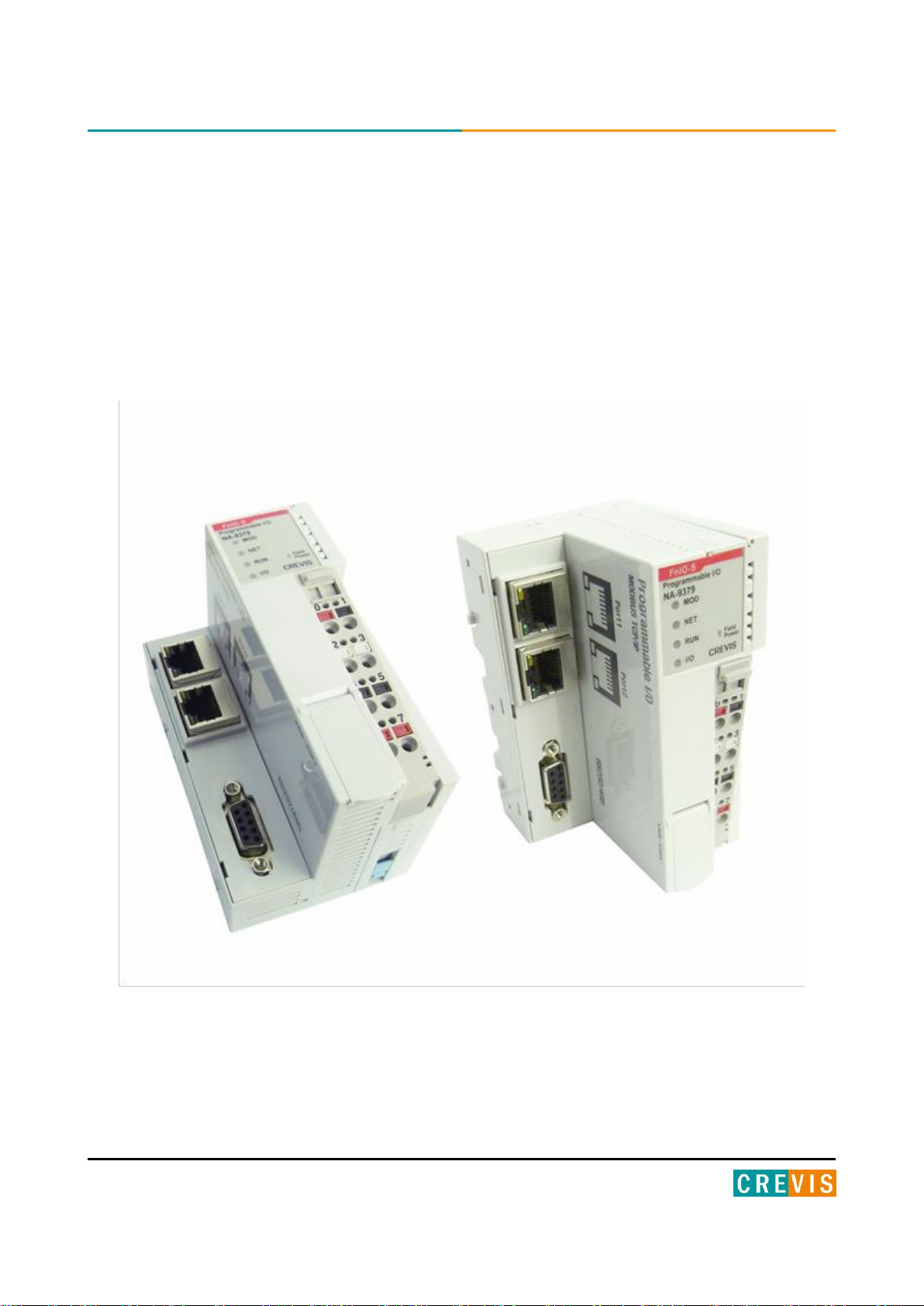
MODBUS Programmable I/O
Copyright(C) CREVIS Co.,Ltd Support +82-31-899-4599 URL : www.crevis.co.kr
Version 1.03
Page 2

2 MODBUS Programmable I/O NA-9379 FnIO S-Series
DOCUMENT CHANGE SUMMARY
REV
PAGE
REMARKS
DATE
EDITOR
1.0
New Document
Draft
2013/04/05
JE Kang
1.01
Reorganize
Draft
2014/03/25
YMKIM
1.02 Modify the Pin Description
2014/05/08
YMKIM
1.03
Reorganize2
Draft
2014/05/29
YMKIM
Copyright(C) CREVIS Co.,Ltd Support +82-31-899-4599 URL : www.crevis.co.kr
Page 3

3 MODBUS Programmable I/O NA-9379 FnIO S-Series
CONTENTS
1. Important Notes ......................................................................................................................................................... 7
1.1. Safety Instruction ...................................................................................................................................... 8
1.1.1. Symbols ......................................................................................................................................................... 8
1.1.2. Safety Notes ................................................................................................................................................ 8
1.1.3. Certification (TBD) ..................................................................................................................................... 8
2. S-Series System ........................................................................................................................................................... 9
2.1. Electrical Interface ..................................................................................................................................... 9
2.2. I/O Process Image Map ....................................................................................................................... 10
3. Specification ................................................................................................................................................................ 11
3.1. General Specification ............................................................................................................................. 11
3.2. Interface Specification........................................................................................................................... 12
4. Module Description ................................................................................................................................................. 13
4.1. NA-9379 (MODBUS Programmable I/O) ...................................................................................... 13
4.2. LED Indicator ............................................................................................................................................. 14
3.2.1. Indicator Status and Flash Rates ...................................................................................................... 14
3.2.2. Module Status LED (MOD) ................................................................................................................. 15
3.2.3. Network Status LED (NET) .................................................................................................................. 15
3.2.4. PLC Run/Stop Status LED (RUN) ...................................................................................................... 15
3.2.5. Extension Module Status LED (I/O) ................................................................................................ 16
3.2.6. Field Power Status LED ........................................................................................................................ 16
3.3. RJ-45 Socket , RS232/485 Port ......................................................................................................... 17
3.4. Toggle Switch , Push Button ............................................................................................................. 17
Copyright(C) CREVIS Co.,Ltd Support +82-31-899-4599 URL : www.crevis.co.kr
Page 4

4 MODBUS Programmable I/O NA-9379 FnIO S-Series
3.5. RTB Terminal Block ................................................................................................................................ 18
3.6. Pin Description ......................................................................................................................................... 18
3.7. Dimension .................................................................................................................................................. 19
4. Mechanical Setup ..................................................................................................................................................... 20
4.3. Inserting and Removing the Module. ............................................................................................ 20
4.4. Removable Terminal Block (RTB) ..................................................................................................... 21
4.5. Method of Wiring. .................................................................................................................................. 21
5. Various Functions of PIO (With IO Guide Pro) ........................................................................................... 22
5.1. Connect IO Guide Pro (MODBUS Serial) ...................................................................................... 22
5.2. Confirmation of Network Information. ......................................................................................... 25
5.3. BootP/DHCP Setting .............................................................................................................................. 27
5.4. Setup IP Address ..................................................................................................................................... 29
5.5. Serial Communication Settings......................................................................................................... 32
5.6. Memory Reset .......................................................................................................................................... 34
5.7. RTC(Real Time Clock) Function ......................................................................................................... 35
6. Programing the PIO (CoDeSys) .......................................................................................................................... 36
6.1. Download and Install the CoDeSys ................................................................................................ 36
6.2. The Basic Configuration CoDeSys ................................................................................................... 37
6.2.1. Installation of XML ................................................................................................................................. 37
6.2.2. Created Project ........................................................................................................................................ 41
6.2.3. CoDeSys User Interface ........................................................................................................................ 42
6.2.4. Setup I/O .................................................................................................................................................... 43
6.3. MODBUS TCP Setting ........................................................................................................................... 46
Copyright(C) CREVIS Co.,Ltd Support +82-31-899-4599 URL : www.crevis.co.kr
Page 5

5 MODBUS Programmable I/O NA-9379 FnIO S-Series
6.4. Network Variable .................................................................................................................................... 50
6.5. Download and Monitoring ................................................................................................................. 53
7. Upgrade Firmware ................................................................................................................................................... 54
7.1. Using IAP over Ethernet....................................................................................................................... 54
8. Trouble Shooting ...................................................................................................................................................... 56
8.1. How to diagnose by LED indicator ................................................................................................. 56
8.2. How to diagnose when device couldn’t communicate network ....................................... 57
APPENDIX A - MODBUS INTERFACE ........................................................................................................................ 58
A.1 MODBUS Interface Register / Bit Map .......................................................................................... 58
A.2 MODBUS Transmission Mode ........................................................................................................... 59
A.2.1. RTU Transmission Mode ..................................................................................................................... 59
A.2.2. ASCII Transmission Mode ................................................................................................................... 59
A.3 Supported MODBUS Function Codes ............................................................................................ 59
A.3.1. 1 (0x01) Read Coils ................................................................................................................................ 60
A.3.2. 2 (0x02) Read Discrete Inputs .......................................................................................................... 61
A.3.3. 3 (0x03) Read Holding Registers ..................................................................................................... 62
A.3.4. 4 (0x04) Read Input Registers .......................................................................................................... 63
A.3.5. 5 (0x05) Write Single Coil ................................................................................................................... 64
A.3.6. 6 (0x06) Write Single Register .......................................................................................................... 65
A.3.7. 8 (0x08) Diagnostics .............................................................................................................................. 66
A.3.8. 15 (0x0F) Write Multiple Coils .......................................................................................................... 69
A.3.9. 16 (0x10) Write Multiple Registers ................................................................................................. 70
A.3.10. 23 (0x17) Read/Write Multiple Registers .................................................................................... 71
Copyright(C) CREVIS Co.,Ltd Support +82-31-899-4599 URL : www.crevis.co.kr
Page 6

6 MODBUS Programmable I/O NA-9379 FnIO S-Series
A.4 MODBUS Special Register Map........................................................................................................ 72
A.4.1. Adapter Register Mapping ................................................................................................................. 72
A.4.2. Adapter Identification Special Register (0x1000, 4096) ........................................................ 72
A.4.3. Adapter Watchdog Time, other Time Special Register (0x1020, 4128) ......................... 73
A.4.4. Adapter Information Special Register (0x1100, 4352) ........................................................... 74
A.4.5. Adapter Setting Special Register (0x1600, 5632) ..................................................................... 75
A.4.6. Expansion Slot Information Special Register (0x2000, 8192) ............................................. 76
A.5 Example ....................................................................................................................................................... 78
A.5.1. Example of Input Process Image(Input Register) Map .......................................................... 78
A.5.2. Example of Output Process Image(Output Register) Map .................................................. 80
A.6 Error Response ......................................................................................................................................... 82
A.7 MODBUS Reference ............................................................................................................................... 83
APPENDIX B - Product List ........................................................................................................................................... 84
Copyright(C) CREVIS Co.,Ltd Support +82-31-899-4599 URL : www.crevis.co.kr
Page 7

7 MODBUS Programmable I/O NA-9379 FnIO S-Series
Warning!
Caution!
1. Important Notes
Solid state equipment has operational characteristics differing from those of electromechanical equipment.
Safety Guidelines for the Application, Installation and Maintenance of Solid State Controls describes some important
differences between solid state equipment and hard-wired electromechanical devices.
Because of this difference, and also because of the wide variety of uses for solid state equipment, all persons
responsible for applying this equipment must satisfy themselves that each intended application of this equipment is
acceptable.
In no event will CREVIS be responsible or liable for indirect or consequential damages resulting from the use or
application of this equipment.
The examples and diagrams in this manual are included solely for illustrative purposes. Because of the many variables
and requirements associated with any particular installation, CREVIS cannot assume responsibility or liability for actual
use based on the examples and diagrams.
If you don’t follow the directions, it could cause a personal injury, damage to the equipment or explosion
• Do not assemble the products and wire with power applied to the system. Else it may cause an electric arc, which
can result into unexpected and potentially dangerous action by field devices. Arching is explosion risk in
hazardous locations. Be sure that the area is non-hazardous or remove system power appropriately before
assembling or wiring the modules.
• Do not touch any terminal blocks or IO modules when system is running. Else it may cause the unit to an electric
shock or malfunction.
• Keep away from the strange metallic materials not related to the unit and wiring works should be controlled by the
electric expert engineer. Else it may cause the unit to a fire, electric shock or malfunction.
If you disobey the instructions, there may be possibility of personal injury, damage to equipment or
explosion. Please follow below Instructions.
• Check the rated voltage and terminal array before wiring. Avoid the circumstances over 55℃ of temperature.
Avoid placing it directly in the sunlight.
• Avoid the place under circumstances over 85% of humidity.
• Do not place Modules near by the inflammable material. Else it may cause a fire.
• Do not permit any vibration approaching it directly.
• Go through module specification carefully, ensure inputs, output connections are made with the specifications. Use
standard cables for wiring.
• Use Product under pollution degree 2 environment.
Copyright(C) CREVIS Co.,Ltd Support +82-31-899-4599 URL : www.crevis.co.kr
Page 8
8 MODBUS Programmable I/O NA-9379 FnIO S-Series
1.1. Safety Instruction
1.1.1. Symbols
Identifies information about practices or circumstances that can cause an explosion in a
hazardous environment, which may lead to personal injury or death property damage or
economic loss.
Identifies information that is critical for successful application and understanding of the
product.
Identifies information about practices or circumstances that can lead to personal
injury, property damage, or economic loss.
Attentions help you to identity a hazard, avoid a hazard, and recognize the consequences.
1.1.2. Safety Notes
The modules are equipped with electronic components that may be destroyed by electrostatic
discharge. When handling the modules, ensure that the environment (persons, workplace and
packing) is well grounded. Avoid touching conductive components.
1.1.3. Certification (TBD)
Copyright(C) CREVIS Co.,Ltd Support +82-31-899-4599 URL : www.crevis.co.kr
Page 9
9 MODBUS Programmable I/O NA-9379 FnIO S-Series
2. S-Series System
2.1. Electrical Interface
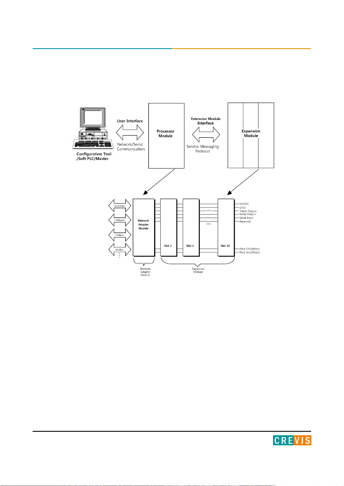
• Network Adapter Module
The Network Adapter Module forms the link between the field bus and the field devices with the Expansion Modules.
The connection to different field bus systems can be established by each of the corresponding Network Adapter
Module, e.g. for SyncNet, PROFIBUS, CANopen, DeviceNet, Ethernet/IP, CC-Link, MODBUS/Serial,
MODBUS/TCP etc.
• Expansion Module
The Expansion Modules are supported a variety of input and output field devices. There are digital and analog
input/output modules and special function modules.
• Two types of Message
Service Messaging / I/O Messaging
Copyright(C) CREVIS Co.,Ltd Support +82-31-899-4599 URL : www.crevis.co.kr
Page 10
10 MODBUS Programmable I/O NA-9379 FnIO S-Series
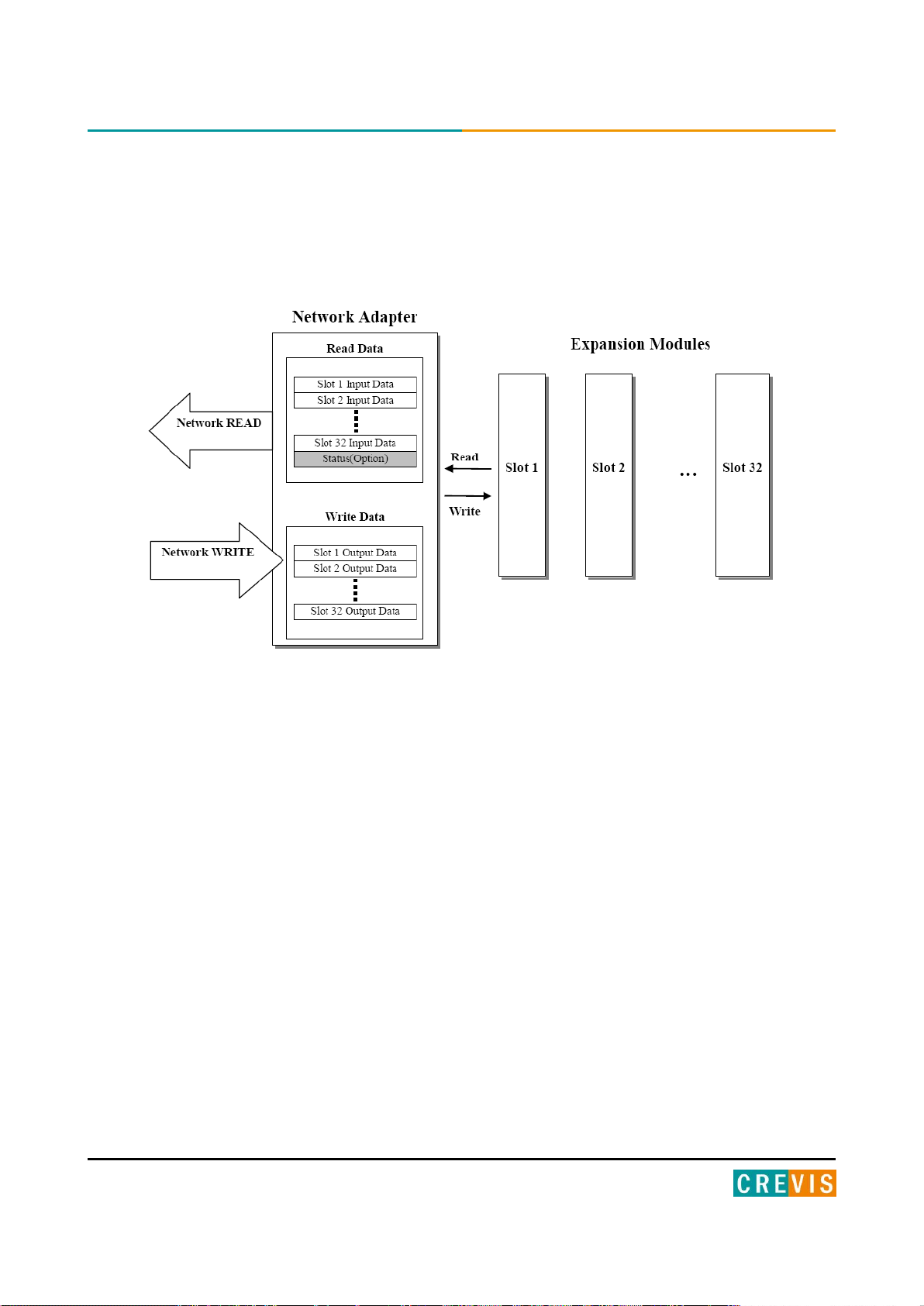
2.2. I/O Process Image Map
An expansion module may have 3 types of data as I/O data, configuration parameter and memory register.
The data exchange between network adapter and expansion modules is done via an I/O process image data by
internal-protocol. The following figure shows the data flow of process image between network adapter and
expansion modules.
Copyright(C) CREVIS Co.,Ltd Support +82-31-899-4599 URL : www.crevis.co.kr
Page 11

11 MODBUS Programmable I/O NA-9379 FnIO S-Series
General Specification
System Power
Supply voltage : 24Vdc nominal
Supply voltage range : 11~28.8Vdc
Protection : Output current limit (Min. 1.5A)
Reverse polarity protection
Power Dissipation
110mA typical @ 24Vdc
Current for I/O Module
1.5A @5Vdc
Isolation
System power to internal logic : Non-isolation
System power I/O driver : Isolation
Field Power
Supply voltage : 24Vdc nominal
Supply voltage range : 11~28Vdc
Max. Current Field Power Contact
DC 10A Max.
Weight
172g
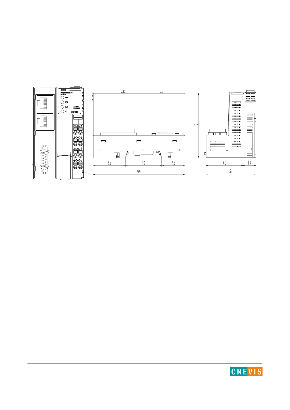
Module Size
54mm x 99mm x 70mm
Environment Condition
Environmental Specifications
Operating Temperature
Storage Temperature
Relative Humidity
Mounting
-20℃~60℃
-40℃~85℃
5% ~ 90% non-condensing
DIN rail
General Specifications
Shock Operating
IEC 60068-2-6
Vibration/shock resistance
Based on IEC 60068-2-6
Sine Vibration
- 10 ~ 25 Hz : 0.5mm
- 50 ~ 150 Hz : 5g
- 150 ~ 1000 Hz : 2g
- Sweep Rate : 1 Oct/min, 50 cycles
Sine Vibration
- 10 ~ 25 Hz : 0.03 g²/Hz
- 25 ~ 50 Hz : 0.05 g²/Hz
- 50 ~ 150 Hz : 0.15 g²/Hz
- 150 ~ 1000 Hz : 0.01 g²/Hz
- Test time : 5hrs for each test
EMC resistance burst/ESD
EN 61000-6-2 : 2005
EN 61000-6-4/ALL : 2011
Installation Pos. / Protect. Class
Variable/IP20
Product Certifications
TBD
3. Specification
3.1. General Specification
Copyright(C) CREVIS Co.,Ltd Support +82-31-899-4599 URL : www.crevis.co.kr
Page 12

12 MODBUS Programmable I/O NA-9379 FnIO S-Series
Programmable Specification
Programming
CoDeSys V3.5 SP3 Patch 1
Program Memory
512 Kbytes
Data Memory
512 Kbytes
%IW0~%IW639 (640 word Input and Internal memory)
%QW0~%QW639 (640 word Output and Internal memory)
%MW0~%MW639 (640 word Internal memory)
Non-Volatile Memory
32 Kbytes (Retain : 16Kbytes, Flag : 16Kbytes
Run-Time system
Multiple PLC Task
Program Languages
IEC 61131-3 (LD, IL, ST, FBD, SFC)
RTC
Retain Time : 6 days
Accuracy : <2min/month
Max. Task
2
Max. Cycle Task
2
Max. Status Task
1
Process Time
3us (100Instruction)
Interface Specification
Adapter Type
Master & Slave Node (MODBUS TCP)
Max. Expansion Module
32 slots
Max. Input Size
126 Words (252 Byte)
Max. Output Size
126 Words (252 Byte)
Max. Nodes
Limited by Ethernet Specification
Baudrate
10/100Mps, Auto-negotiation, Full Duplex
Interface Connector
RJ-45 socket * 2pcs
Protocol
MODBUS TCP, DHCP, BOOTP, SNMP
Max. Socket
18 (UDP : 6, TCP : 12, TCP_LISTEN : 6)
Other Serial Port
RS232/485 for MODBUS RTU, Touch Pannel or IOGuide
Serial Configuration (RS232/485)
Node : 1(default)
Baudrate : 38400(default)
Data bit : 8(default)
Parity bit : No parity(default)
Stop bit : 1(default)
Indicator
4 LEDs (NET LED is Not used)
1 Green/Red, Module Status (MOD)
1 Green/Red, Run Status (RUN)
1 Green/Red, Extension Module Status (I/O)
1 Green, Field Power Status
3.2. Interface Specification
Copyright(C) CREVIS Co.,Ltd Support +82-31-899-4599 URL : www.crevis.co.kr
Page 13
13 MODBUS Programmable I/O NA-9379 FnIO S-Series
4. Module Description
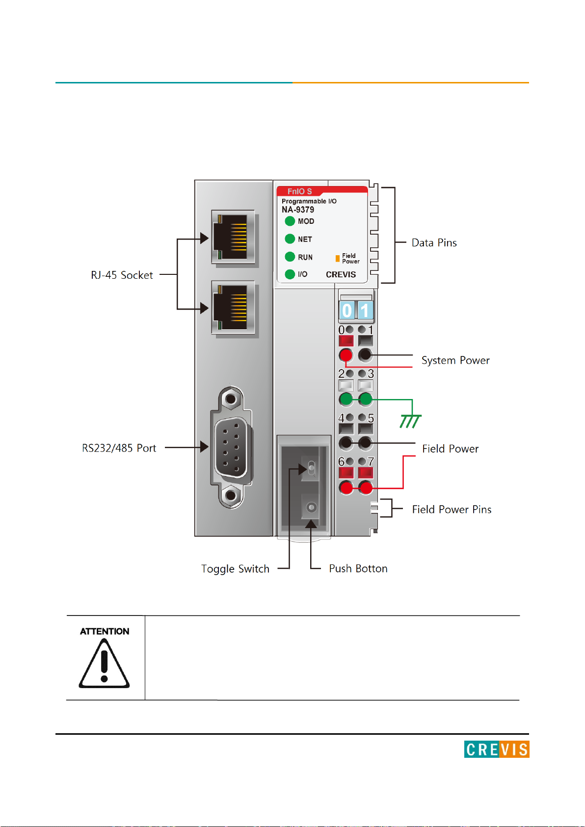
4.1. NA-9379 (MODBUS Programmable I/O)
The modules are not hot swappable and should be not removed in power on condition.
Copyright(C) CREVIS Co.,Ltd Support +82-31-899-4599 URL : www.crevis.co.kr
Page 14
14 MODBUS Programmable I/O NA-9379 FnIO S-Series
LED is:
Constantly on
LED Off
Constantly off
LED Flickering
Equal on and off times with a frequency of approximately 10 Hz: on for approximately
50ms and off for approximately 50ms.
LED Blinking
Equal on and off times with a frequency of approximately 2, 5Hz: on for approximately
200ms followed by off for approximately 200ms.
LED Single flash
One short flash (approximately 200ms) followed by a long off phase (approximately
1000ms)
LED Double flash
A sequence of two short flashes (approximately 200ms), separated by an off phase
(approximately 200ms). The sequence is finished by a long off phase (approximately
1000ms).
LED Triple flash
A sequence of three short flashes (approximately 200ms), separated by an off phase
(approximately 200ms). The sequence is finished by a long off phase (approximately
1000ms).
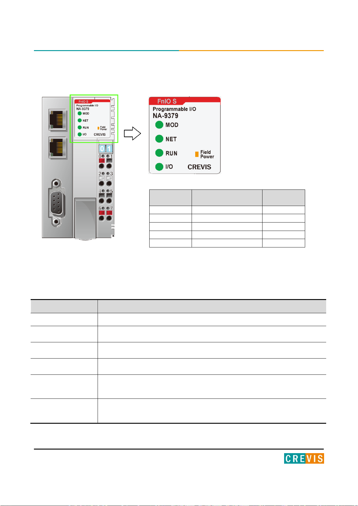
LED No.
LED Function /
Description
LED Color
MOD
Module Status
Green/Red
NET
Not Used
-
RUN
Error Status
Green/Red
I/O
Extension module Status
Green/Red
Field Power
Field Power Enable
Green
4.2. LED Indicator
3.2.1. Indicator Status and Flash Rates
Copyright(C) CREVIS Co.,Ltd Support +82-31-899-4599 URL : www.crevis.co.kr
Page 15

15 MODBUS Programmable I/O NA-9379 FnIO S-Series
State
LED is :
To indicate :
No Power
Off
No power is supplied to the unit.
Device Operational
Green
The unit is operating in normal condition.
Device in Standby
Blinking Green
The EEPROM parameter is not initialized yet.
Serial Number is zero value (0x00000000)
IAP Mode
Flashing Green
IAP Mode : Available for firmware download using FireFox.
Minor Fault
Blinking Red
The unit has occurred recoverable fault in self-testing.
- EEPROM checksum fault
Unrecoverable Fault
Red
The unit has occurred unrecoverable fault in self-testing.
- Firmware fault
State
LED is :
To indicate :
Not Used
State
LED is :
To indicate :
Not Programmed
OFF
Not Power is supplied or the unit or Not programmed
Run
ON
PLC Run
Stop
Blinking Green
PLC Stop
Error
Blinking Red
Failure of Module Configuration
3.2.2. Module Status LED (MOD)
3.2.3. Network Status LED (NET)
3.2.4. PLC Run/Stop Status LED (RUN)
Copyright(C) CREVIS Co.,Ltd Support +82-31-899-4599 URL : www.crevis.co.kr
Page 16

16 MODBUS Programmable I/O NA-9379 FnIO S-Series
State
LED is :
To indicate :
Not Powered
No Expansion Module
Off
Device has no expansion module or may not be powered
On-line,
Do not Exchanging I/O
Flashing Green
Extension module is normal but does not exchanging I/O data
(Passed the expansion module configuration).
Connection,
Run Exchanging IO
Green
Exchanging I/O data
Connection fault
during exchanging IO
Red
One or more expansion module occurred in fault state.
- Changed expansion module configuration.
- expansion module communication failure.
Expansion
Configuration Failed
Flashing Red
Failed to initialize expansion module
- Detected invalid expansion module ID.
- Overflowed Input / Output Size
- Too many expansion module
- Initial protocol failure
- Mismatch vendor code between adapter and expansion module.
State
LED is :
To indicate :
Not Supplied Field Power
Off
Not supplied 24V dc field power, 5Vdc System Power.
Supplied Field Power
Green
Supplied 24V dc field power, 5Vdc System Power.
3.2.5. Extension Module Status LED (I/O)
3.2.6. Field Power Status LED
Copyright(C) CREVIS Co.,Ltd Support +82-31-899-4599 URL : www.crevis.co.kr
Page 17
17 MODBUS Programmable I/O NA-9379 FnIO S-Series
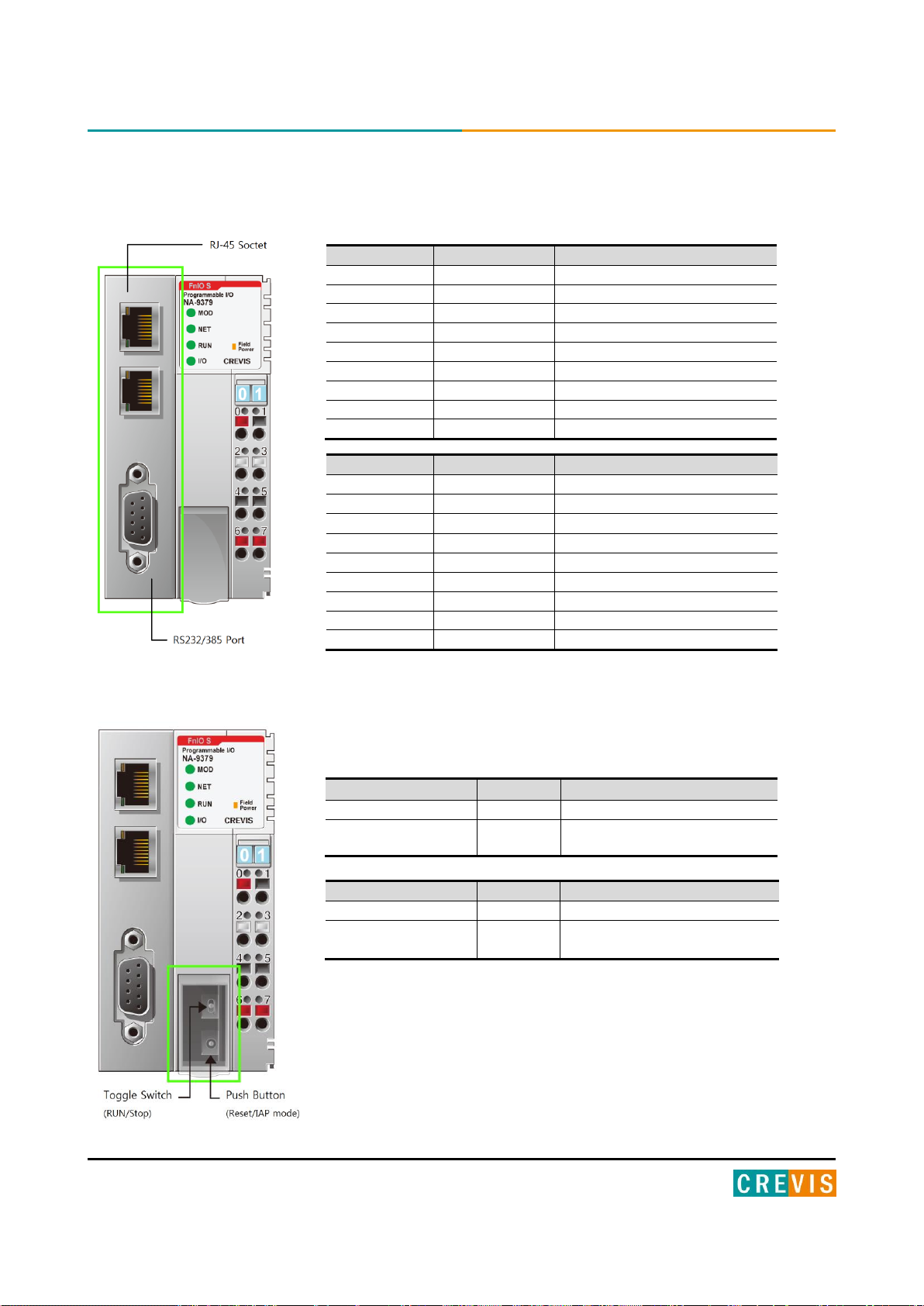
RJ-45
Signal Name
Description
1
TD+
Transmit + 2 TD-
Transmit - 3 RD+
Receive + 4 - 5
-
6
RD-
Receive -
7
- 8
-
Case
Shield
RS 232/485
Signal Name
Description
1
-
2
RXD
RS232 RXD
3
TXD
RS232 TXD
4
-
5
GND
RS232 GND
6
D+
RS 485 D+ 7 - 8
D-
RS485 D- 9 -
Toggle Switch Status
Module is
Description
UP
RUN
PLC Run
DOWN
STOP
PLC Stop
(Fault Action is performed)
Push Button
Module is
Description
Press and release.
Reset
Reset the PLC and then stop.
Hold down and reset
the power.
IAP mode
Available for firmware download
using FireFox
3.3. RJ-45 Socket , RS232/485 Port
3.4. Toggle Switch , Push Button
Copyright(C) CREVIS Co.,Ltd Support +82-31-899-4599 URL : www.crevis.co.kr
Page 18
18 MODBUS Programmable I/O NA-9379 FnIO S-Series
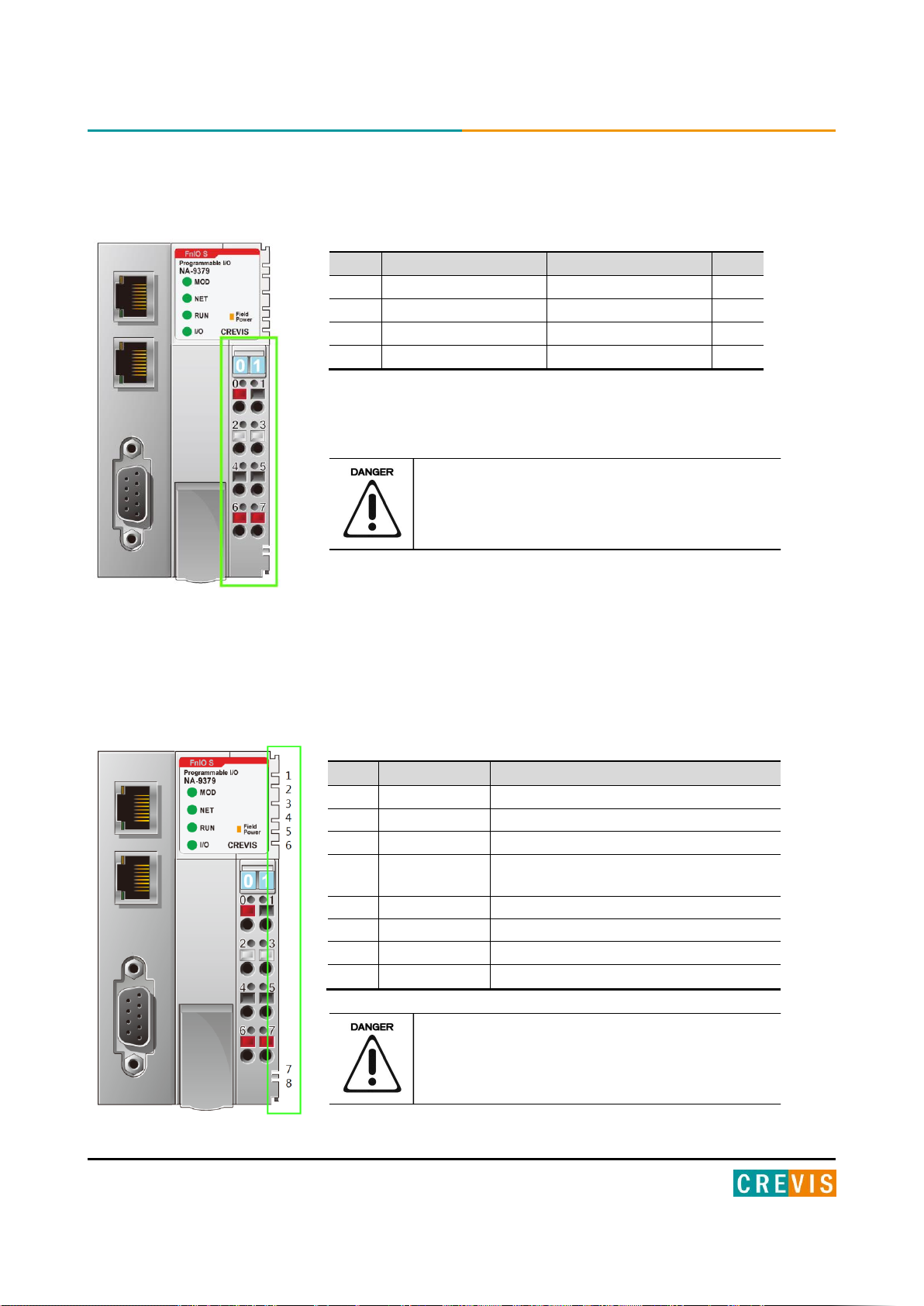
Pin
Signal Description
Signal Description
Pin
0
System Power 24V
System Power 0V
1
2
F.G
F.G
3 4 Field Power 0V
Field Power 0V
5
6
Field Power 24V
Field Power 24V
7
No.
Name
Description
1
System Vcc
System supply voltage (5V dc).
2
System GND
System Ground.
3
Token Output
Token output port of Processor module.
4
Serial Output
Transmitter output port of Processor
module.
5
Serial Input
Receiver input port of Processor module.
6
Reserved
Reserved for bypass Token.
7
Field GND
Field Ground.
8
Field Vcc
Field supply voltage (24Vdc).
3.5. RTB Terminal Block
- System Power: The power for starting up CPU.
- Field Power: The power for input and output line.
Do not use an incorrect voltage/frequency!
The use of an incorrect supply voltage or frequency
can cause severe damage to the component.
3.6. Pin Description
Communication between the Network adapter and the expansion module as well as system / field power supply of the
bus modules is carried out via the internal bus. It is comprised of 6 data pin and 2 field power pin.
Do not touch data and field power pins in order to
avoid soiling and damage by ESD noise.
Copyright(C) CREVIS Co.,Ltd Support +82-31-899-4599 URL : www.crevis.co.kr
Page 19
19 MODBUS Programmable I/O NA-9379 FnIO S-Series
3.7. Dimension
(mm)
Copyright(C) CREVIS Co.,Ltd Support +82-31-899-4599 URL : www.crevis.co.kr
Page 20
20 MODBUS Programmable I/O NA-9379 FnIO S-Series
4. Mechanical Setup
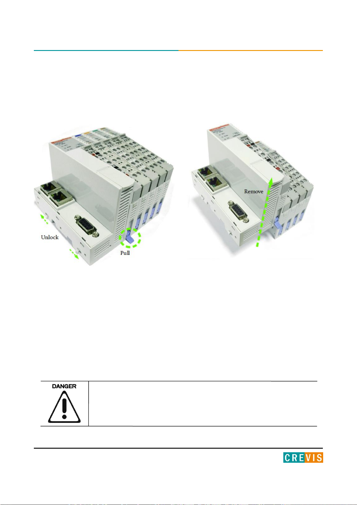
4.3. Inserting and Removing the Module.
As above figure in order to safeguard the FnIO module from jamming, it should be fixed onto the DIN rail with locking
level. To do so, fold on the upper of the locking lever.
To pull out the FnIO module, unfold the locking lever as below figure.
Before work is done on the components, the voltage supply must be turned off.
Copyright(C) CREVIS Co.,Ltd Support +82-31-899-4599 URL : www.crevis.co.kr
Page 21
21 MODBUS Programmable I/O NA-9379 FnIO S-Series
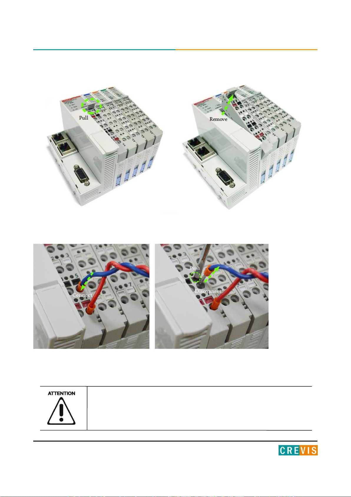
4.4. Removable Terminal Block (RTB)
4.5. Method of Wiring.
Connecting or removing the cable by pushing the terminal button for the relevant points.
The use of an incorrect supply voltage or frequency can cause severe damage to the
component.
Copyright(C) CREVIS Co.,Ltd Support +82-31-899-4599 URL : www.crevis.co.kr
Page 22
22 MODBUS Programmable I/O NA-9379 FnIO S-Series
5. Various Functions of PIO (With IO Guide Pro)
Crevis IO Guide Pro is compatible with the PIO(NA-9379).
The basic parameter set-up and configuration for the PIO is available via the IO Guide Pro.
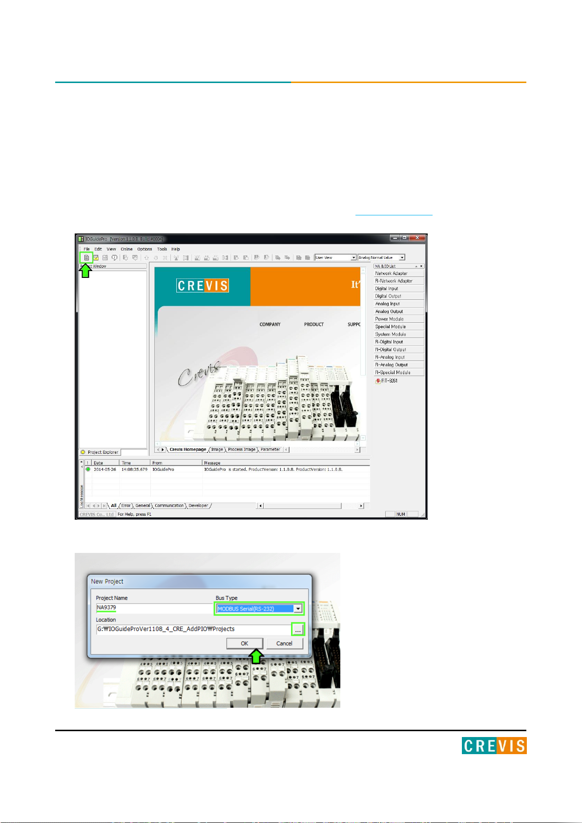
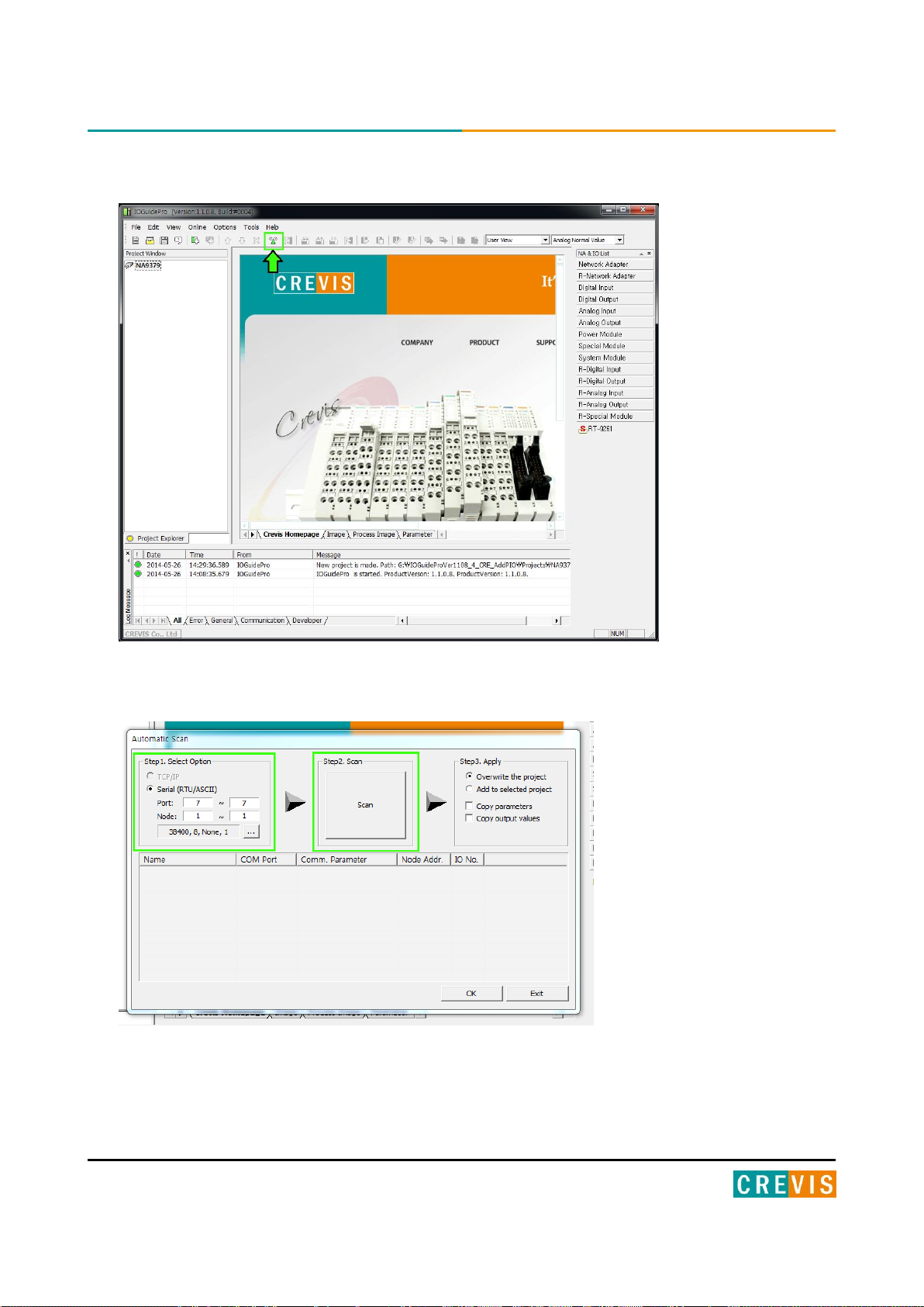
5.1. Connect IO Guide Pro (MODBUS Serial)
(1) Installation program-IO Guide Pro that provides CREVIS(www.crevis.co.kr).
(2) Open the IO Guide and Click on the ‘New project’ Icon.
(2) Write the ‘Project Name’ and Select of bus type Specify the local and Click on the ‘OK’ button.
Copyright(C) CREVIS Co.,Ltd Support +82-31-899-4599 URL : www.crevis.co.kr
Page 23
23 MODBUS Programmable I/O NA-9379 FnIO S-Series
(1) After creating a project and click the ‘Automatic scan’ Icon.
(4) Write the value(Port, node, Baudrate) click the ‘Automatic scan’ button.
Copyright(C) CREVIS Co.,Ltd Support +82-31-899-4599 URL : www.crevis.co.kr
Page 24
24 MODBUS Programmable I/O NA-9379 FnIO S-Series
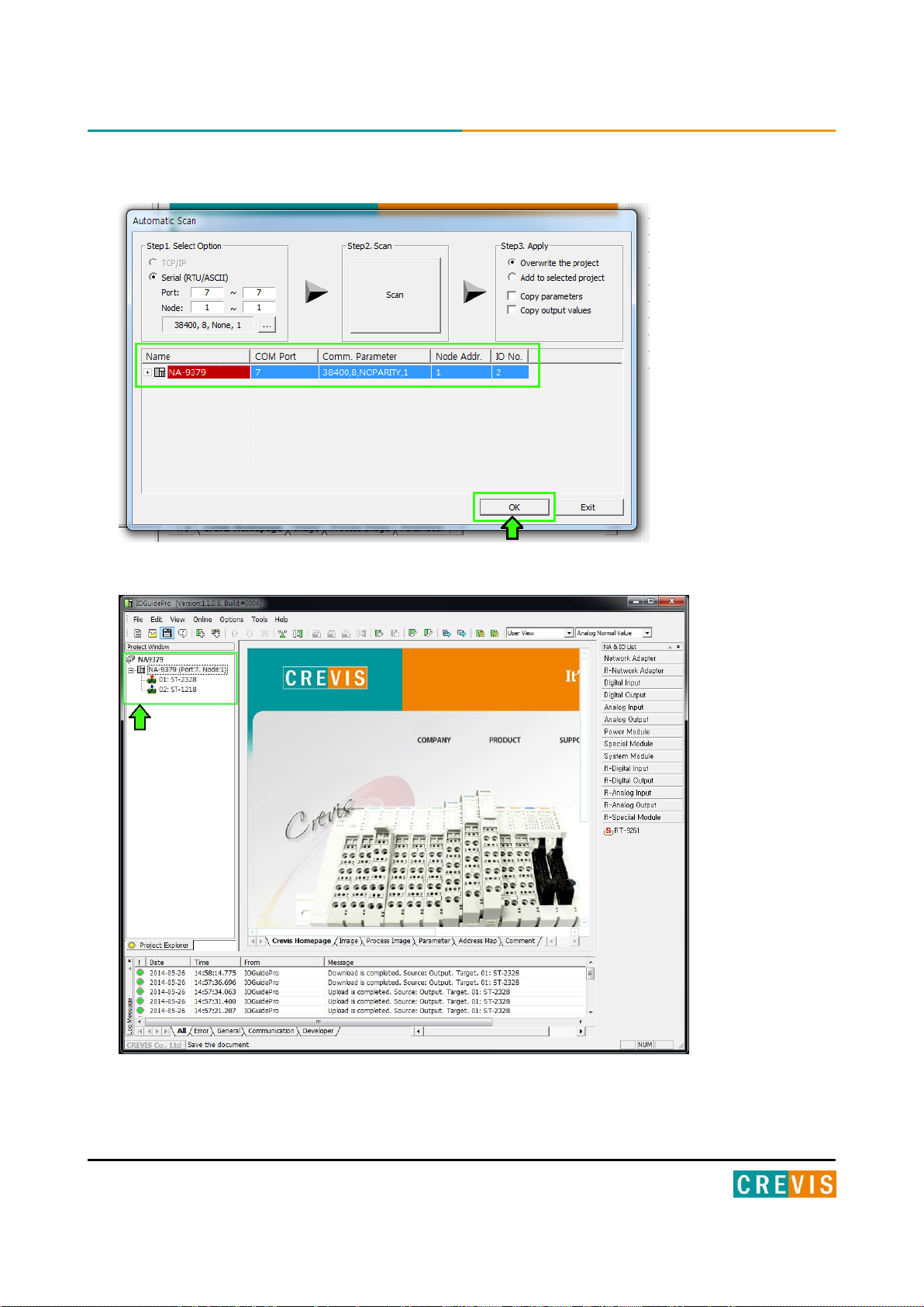
(1) After the scan completes, click the ‘OK’ button.
(1) It is ready to use the IO Guide Pro.
Copyright(C) CREVIS Co.,Ltd Support +82-31-899-4599 URL : www.crevis.co.kr
Page 25
25 MODBUS Programmable I/O NA-9379 FnIO S-Series
5.2. Confirmation of Network Information.
You can see by checking the IP Address , Subnet Mask, Gate Way, Mac Address of NA-9379 .
* IP Address : Also known as an "IP number" or simply an "IP," this is a code made up of numbers separated by
three dots that identifies a particular computer on the Internet. Every computer, whether it be a Web server or the
computer you're using right now, requires an IP address to connect to the Internet. IP addresses consist of four sets
of numbers from 0 to 255, separated by three dots.
* Subnet Mask : A subnet mask is a number that defines a range of IP addresses that can be used in a network. (It
is not something you wear on your head to keep subnets out.) Subnet masks are used to designate sub networks, or
subnets, which are typically local networks LANs that are connected to the Internet. Systems within the same
subnet can communicate directly with each other, while systems on different subnets must communicate through a
router.
* Gate Way : A gateway is either hardware or software that acts as a bridge between two networks so that data can
be transferred between a number of computers.
* Mac Address : A MAC address is a hardware identification number that uniquely identifies each device on a
network. The MAC address is manufactured into every network card, such as an Ethernet card or Wi-Fi card, and
therefore cannot be changed.
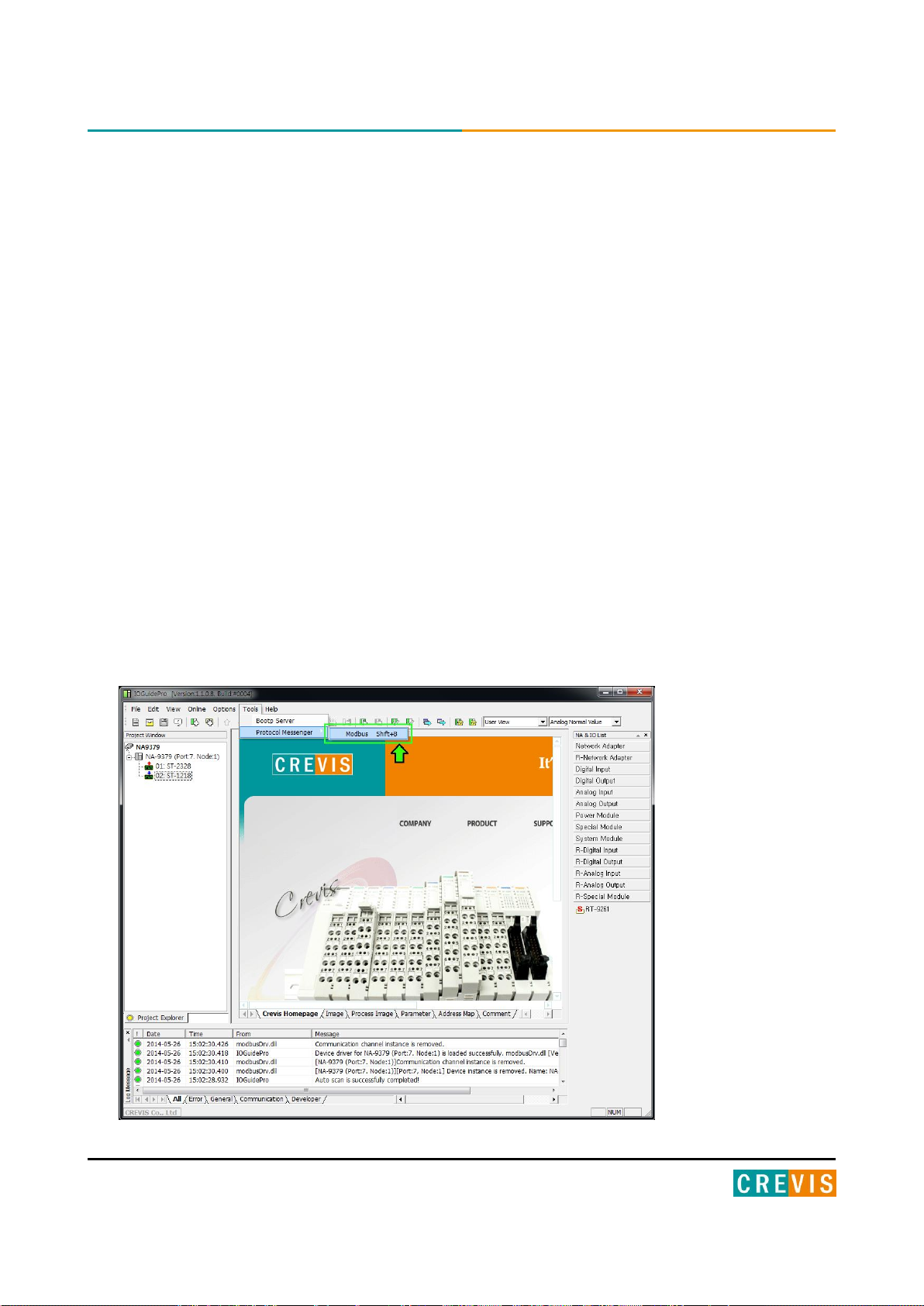
(1) Run ‘[Crevis] -> [IOGuidePro] -> [Protocol Messenger] -> [Modbus]’
Copyright(C) CREVIS Co.,Ltd Support +82-31-899-4599 URL : www.crevis.co.kr
Page 26
26 MODBUS Programmable I/O NA-9379 FnIO S-Series
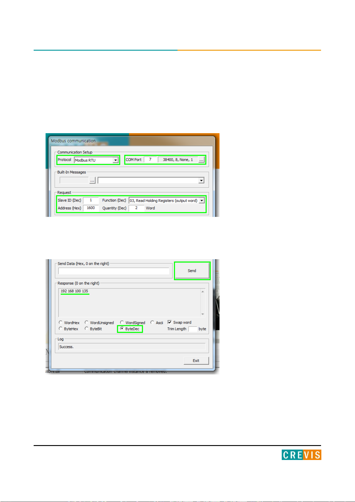
(2) Write the value of each.
*Protocol : Modbus RTU
*ComPort : User Port / Baudrate : 38400(default)
*Address(Hex) : 1600 (IP Address Register)
:1602 (IP Subnet Mask Register)
:1604 (Gate way Register)
:1610 (Mac Address Register)
*Function(Dec) : 03, Read Holding Registers
(3) After clicking the ‘send’ button and confirm the necessary information.
If you choose to 'ByteDec', More easy to see.
Copyright(C) CREVIS Co.,Ltd Support +82-31-899-4599 URL : www.crevis.co.kr
Page 27

27 MODBUS Programmable I/O NA-9379 FnIO S-Series
5.3. BootP/DHCP Setting
You can selected to ‘IP Setting method’.
* BOOTP: short for Bootstrap Protocol, is a UDP network protocol used by a network client to obtain its IP
address automatically. This is usually done in the bootstrap process of computers or operating systems running on
them. The BOOTP servers assign the IP address from a pool of addresses to each client.
* DHCP: set of rules used by communications devices such as a computer, router or network adapter to allow the
device to request and obtain an IP address from a server which has a list of addresses available for assignment.
(1) Run ‘[Crevis] -> [IOGuidePro] -> [Protocol Messenger] -> [Modbus]’
Copyright(C) CREVIS Co.,Ltd Support +82-31-899-4599 URL : www.crevis.co.kr
Page 28

28 MODBUS Programmable I/O NA-9379 FnIO S-Series
(2) Write the value of each.
*Protocol : Modbus RTU
*ComPort : User Port / Baudrate : 38400(default)
*Address(Hex) : 160B (IP Setting Method Register)
*Function(Dec) : 16, Write Multiple registers
(3) Write the register value and click the ‘Send’ button.
*Not Use : 0000 / *BootP Setting : 8000 / *DHCP Setting : 8001
Copyright(C) CREVIS Co.,Ltd Support +82-31-899-4599 URL : www.crevis.co.kr
Page 29

29 MODBUS Programmable I/O NA-9379 FnIO S-Series
5.4. Setup IP Address
You can assign the IP Address manually via the setting of Bootp server.
Default IP Address is 192.168.100.100
(1) Run ‘[Crevis] [IOGuidePro] [Bootp Server]’
NA9379 is a model that supports DHCP and Bootp.
If you have a DHCP server on the same communications,
IP settings from Bootp is impossible.
In this case, set the IP from the DHCP server.
Copyright(C) CREVIS Co.,Ltd Support +82-31-899-4599 URL : www.crevis.co.kr
Page 30

30 MODBUS Programmable I/O NA-9379 FnIO S-Series
(2) Power on the NA9379, and Click the ‘Start Bootp’ button.
(3) Double Click ‘MAC address of NA9379’
Turn on the power of NA-9379, and Retry 2imes for 4 seconds.
IP settings will be within that time.
Copyright(C) CREVIS Co.,Ltd Support +82-31-899-4599 URL : www.crevis.co.kr
Page 31

31 MODBUS Programmable I/O NA-9379 FnIO S-Series
(4) Set the IP, and click ‘OK’.
(5) Finish
Subnet Mask and Gateway is
assigned automatically by the value that is set in the computer.
Copyright(C) CREVIS Co.,Ltd Support +82-31-899-4599 URL : www.crevis.co.kr
Page 32

32 MODBUS Programmable I/O NA-9379 FnIO S-Series
0x160A
15
14
13
12
11
10 9 8 7 6 5 4 3 2 1 0
- 1 nibble : Data bit(0 : 8bit(default), 1 : 9bit)
- 2 nibble : Stop bit(0 : 1bit(default), 1 : 2bit)
- 3 nibble : Parity bit(0 : none(default), 1: even, 2 : odd)
- 4 nibble : Reserve
0x1607
15
14
13
12
11
10 9 8 7 6 5 4 3 2 1 0
0x1609
15
14
13
12
11
10 9 8 7 6 5 4 3 2 1 0
1 : 2400 2 : 4800 3 : 9600 4 : 19200
5 : 38400 (default) 6 : 57600 7 : 115200
5.5. Serial Communication Settings
Setting according to the each communication state is possible Because NA-9379 is available the
RS232 and RS485 Serial Communications.
• Station Setting
The following illustration is an area of Register 0x160A address that can be used to set the code of Serial
communication. High 1byte is the area of rs232, and Low 1byte is the area of rs485.
It is possible to set a maximum of 247 for each area. (default : 1)
MSB LSB
RS232C Modbus station RS485 Modbus station
• RS232/ RS485 Communication setting
The options for the communication can be selected.
RS232 can be selected from the register address, “0x1606”.
RS485 can be selected from the register address, “0x1608”.
MSB LSB
Data bit Stop bit Parity bit Reserve
MSB LSB
Data bit Stop bit Parity bit Reserve
RS485
• Baudrate setting
The baudrate from 1200bps to 115200bps is supported.
RS232 can be selected from the register address, “0x1606”.
RS485 can be selected from the register address, “0x1608”.
RS232
Copyright(C) CREVIS Co.,Ltd Support +82-31-899-4599 URL : www.crevis.co.kr
Page 33

33 MODBUS Programmable I/O NA-9379 FnIO S-Series
(1) Run ‘[Crevis] -> [IOGuidePro] -> [Protocol Messenger] -> [Modbus]’
(2) Write the value of each.
*Protocol : Modbus RTU
*ComPort : User Port / Baudrate : 38400(default)
*Address(Hex) : 1606 (RS232 Baudrate Register)
:1607 (RS232 Use bit Setting Register)
:1608 (RS485 Baudrate Register)
:1609 (RS485 Use bit Setting Register)
*Function(Dec) : When the value is write - 16, Write Multiple registers
When the value is read - 03, Read Holding Registers
(3) confirm the necessary information.
*When the value is write *When the value is read
write the desired value and click the Send button. Click the Send button and confirm the value.
Copyright(C) CREVIS Co.,Ltd Support +82-31-899-4599 URL : www.crevis.co.kr
Page 34

34 MODBUS Programmable I/O NA-9379 FnIO S-Series
5.6. Memory Reset
data field 0x55AA makes the remote device to restart with factory default setup of EEPROM.
*All expansion slot configuration parameters are cleared.
(1) Run ‘[Crevis] -> [IOGuidePro] -> [Protocol Messenger] -> [Modbus]’
(2) Write the value of each.
*Protocol : Modbus RTU
*ComPort : User Port / Baudrate : 38400(default)
*Address(Hex) : 0001 (Factory default setup)
*Function(Dec) : When the value is write – 08, Diagnostics
(3) Write the register value and click the ‘Send’ button.
*Value : 0x55AA
Copyright(C) CREVIS Co.,Ltd Support +82-31-899-4599 URL : www.crevis.co.kr
Page 35

35 MODBUS Programmable I/O NA-9379 FnIO S-Series
5.7. RTC(Real Time Clock) Function
A real-time clock (RTC) is a computer clock (most often in the form of an integrated circuit) that keeps
track of the current time. RTC information of NA-9379 is stored in address 0x1620 in the Register,
also can be read.
(1) Run ‘[Crevis] -> [IOGuidePro] -> [Protocol Messenger] -> [Modbus]’
(2) Write the value of each.
*Protocol : Modbus RTU
*ComPort : User Port / Baudrate : 38400(default)
*Address(Hex) : 1620 (RTC Register)
*Function(Dec) : When the value is write - 16, Write Multiple registers
When the value is read - 03, Read Holding Registers
(3) confirm the necessary information.
*When the value is write *When the value is read
write the desired value and click the Send button. Click the Send button and confirm the value.
Copyright(C) CREVIS Co.,Ltd Support +82-31-899-4599 URL : www.crevis.co.kr
Page 36

36 MODBUS Programmable I/O NA-9379 FnIO S-Series
6. Programing the PIO (CoDeSys)
6.1. Download and Install the CoDeSys
Please use the CoDeSys version V3.5.3.1 (V3.5 SP3 Patch 1)
Except for the above version, any versions including the latest version
will not be allowed for PIO(NA-9379).
Unzip the downloaded file, and Installation ‘Setup_CoDeSysV35SP3Patch1.exe’
Copyright(C) CREVIS Co.,Ltd Support +82-31-899-4599 URL : www.crevis.co.kr
Page 37

37 MODBUS Programmable I/O NA-9379 FnIO S-Series
6.2. The Basic Configuration CoDeSys
6.2.1. Installation of XML
(1) Run the CoDeSys program
(2) [Tools] [Options], Click ‘Predefined feature sets…’
(3) Standard Professional, Click ‘OK’
Copyright(C) CREVIS Co.,Ltd Support +82-31-899-4599 URL : www.crevis.co.kr
Page 38

38 MODBUS Programmable I/O NA-9379 FnIO S-Series
(4) Click ‘OK’
(5) [Tools] [Device Repository], Click ‘PLCs’ and select PIO Description (download to CREVIS
website), Install…
(ProgrammableIO_NA9379.devdesc.xml)
Copyright(C) CREVIS Co.,Ltd Support +82-31-899-4599 URL : www.crevis.co.kr
Page 39

39 MODBUS Programmable I/O NA-9379 FnIO S-Series
*Please check whether they are installed correctly or not.
Copyright(C) CREVIS Co.,Ltd Support +82-31-899-4599 URL : www.crevis.co.kr
Page 40

40 MODBUS Programmable I/O NA-9379 FnIO S-Series
(6) [Tools] [Device Repository], Click ‘Miscellaneous’ and install the slot description and I/O
Description (download to CREVIS website).
(ST-xxxx.devdesc.xml)
*Please check whether they are installed correctly or not.
(CVSRACK.devdesc.xml)
Copyright(C) CREVIS Co.,Ltd Support +82-31-899-4599 URL : www.crevis.co.kr
Page 41

41 MODBUS Programmable I/O NA-9379 FnIO S-Series
6.2.2. Created Project
(1) Run the CoDeSys program.
(2) [File] [New Project], select ‘Standard project’. Write the Project Name and Location.
Click ‘OK’
(3) Select Device : NA9379, select the Programming Language.
Copyright(C) CREVIS Co.,Ltd Support +82-31-899-4599 URL : www.crevis.co.kr
Page 42

42 MODBUS Programmable I/O NA-9379 FnIO S-Series
6.2.3. CoDeSys User Interface
Copyright(C) CREVIS Co.,Ltd Support +82-31-899-4599 URL : www.crevis.co.kr
Page 43

43 MODBUS Programmable I/O NA-9379 FnIO S-Series
6.2.4. Setup I/O
(1) Additional Device
Click on the model you want to use, and click ‘Plug Device’.
For the normal operation, you must select the module image in order through the CoDeSys
like the user configuration.
Auto Scan is not supported.
Copyright(C) CREVIS Co.,Ltd Support +82-31-899-4599 URL : www.crevis.co.kr
Page 44

44 MODBUS Programmable I/O NA-9379 FnIO S-Series
(2) Setting Device Parameter and IO Mapping
Click IO Right click Click ‘Edit object’.
• Parameter setting
Click ‘Digital IOs Configuration’
* The setting unit of the parameter is bytes.
Copyright(C) CREVIS Co.,Ltd Support +82-31-899-4599 URL : www.crevis.co.kr
Page 45

45 MODBUS Programmable I/O NA-9379 FnIO S-Series
• IO Mapping
Click ‘Digital IOs I/O Mapping’
If there are no set values in the red square, you can program the variable area set by the address.
If you use the variable set by the POU or GVL, you can use the variable area after deleting the variable in the
address.
Copyright(C) CREVIS Co.,Ltd Support +82-31-899-4599 URL : www.crevis.co.kr
Page 46

46 MODBUS Programmable I/O NA-9379 FnIO S-Series
6.3. MODBUS TCP Setting
(1) Add Device
Click Device(NA9379) right click Click ‘Add Device…’.
(2) Add Ethernet Adapter
Click ‘Fieldbus’ ‘Ethernet Adapter’ ‘Ethernet’ and ‘Add Device’ Click.
Copyright(C) CREVIS Co.,Ltd Support +82-31-899-4599 URL : www.crevis.co.kr
Page 47

47 MODBUS Programmable I/O NA-9379 FnIO S-Series
(3) Add Device after Selecting Ethernet and Add MODBUS TCP Master
Click Ethernet (Ethernet) right click Click ‘Add Device’
Click ‘Fieldbuses’ ‘Modbus TCP Master’ ‘Modbus TCP Master’ and ‘Add Device’ Click.
Copyright(C) CREVIS Co.,Ltd Support +82-31-899-4599 URL : www.crevis.co.kr
Page 48

48 MODBUS Programmable I/O NA-9379 FnIO S-Series
(4) Add Device after adding MODBUS TCP Master and Add Modbus TCP Slave
Click Modbus_TCP_Master right click Click ‘Add Device’
Click ‘Fieldbuses’ ‘Modbus’ ‘Modbus TCP Slave’ ‘Modbus TCP Slave’ and ‘Add Device’ Click.
Copyright(C) CREVIS Co.,Ltd Support +82-31-899-4599 URL : www.crevis.co.kr
Page 49

49 MODBUS Programmable I/O NA-9379 FnIO S-Series
(5) Configuration the ModbusTCP Slave
Click ‘Modbus_TCP_Slave’(Modbus TCP Slave)
Write Slave IP Address (NA-9379)
Click ‘Modbus Slave Channel’
Add a channel of NA-9379 and Modify Cycle Time
* Default Cycle Time(ms) : 100ms.
Copyright(C) CREVIS Co.,Ltd Support +82-31-899-4599 URL : www.crevis.co.kr
Page 50

50 MODBUS Programmable I/O NA-9379 FnIO S-Series
6.4. Network Variable
(1) Click ‘Application’ Right click and click ‘Add Object’ Click ‘Network Variable List (Sender)’.
* You have to add one more devices in the devices tree.
(2) Define the network properties of the sender GVL
* You have to select UDP as network type.
* List identifier and Node ID is the same concept.
Copyright(C) CREVIS Co.,Ltd Support +82-31-899-4599 URL : www.crevis.co.kr
Page 51

51 MODBUS Programmable I/O NA-9379 FnIO S-Series
(3) Add a Global Network Variable List in the Receiver
* You find a selection list of all GVLs with network properties currently available in the project.
Copyright(C) CREVIS Co.,Ltd Support +82-31-899-4599 URL : www.crevis.co.kr
Page 52

52 MODBUS Programmable I/O NA-9379 FnIO S-Series
(4) Created by Global Variables.
(5) It is possible to create a program using a global variable.
- in prog_sender in the sender application enter the following use of variable iglobvar.
- in prog_Receiver in the receiver application also use variable iglobvar.
Copyright(C) CREVIS Co.,Ltd Support +82-31-899-4599 URL : www.crevis.co.kr
Page 53

53 MODBUS Programmable I/O NA-9379 FnIO S-Series
6.5. Download and Monitoring
(1) Scan network
[Device] [Communication Settings], click ‘Scan network’.
After completing the search, double click the Gateway icon to make it activated.
(2) Login
[Online] [Login] Download to Application Entry into Monitoring Mode [Debug] [RUN]
Copyright(C) CREVIS Co.,Ltd Support +82-31-899-4599 URL : www.crevis.co.kr
Page 54

54 MODBUS Programmable I/O NA-9379 FnIO S-Series
7. Upgrade Firmware
7.1. Using IAP over Ethernet
Using Firefox, can download the firmware.
(1) Apply a power with pushing a reset button.
(2) Execute Firefox
(3) Connect to 192.168.100.10 and login (User ID :1 / Password : 1)
(4) Search the file to download using a search button.
Copyright(C) CREVIS Co.,Ltd Support +82-31-899-4599 URL : www.crevis.co.kr
Page 55

55 MODBUS Programmable I/O NA-9379 FnIO S-Series
(5) Click a Upload Button.
(6) If it finish, you can see a below message (File Upload Done!)
And click a ‘reset mcu’ button.
Copyright(C) CREVIS Co.,Ltd Support +82-31-899-4599 URL : www.crevis.co.kr
Page 56

56 MODBUS Programmable I/O NA-9379 FnIO S-Series
LED Status
Cause
Action
All LED turns off
- No power
- Check main power Cable
- System power is not supplied.
- Contact Sales team and send module
for repair.
MOD LED flashes green
- Failure of initialization EEPROM
parameter.
- Contact Sales team and send module
for repair.
MOD LED flashes red
- Excess of expansion slot
- Excess of IO size
- Wrong IO composition
- Occurrence of EEPROM checksum
error
- Use expansion slot up to 32.
- Compose that IO total size is not
excess.
- Check composition I/O Module
MOD LED is red
- Wrong address ID
- Occurrence critical error in firmware
- Contact Sales team and send module
for repair.
I/O LED turns off
- Failure of realization expansion Module
- None expansion Module
- Check connector status both NA
series and expansion module.
I/O LED flashes red
-Failure of configuration baud rate
- Check communication cable with
Master
- Check power for master.
-Failure of initialization I/O
- Use expansion slot up to 32.
- Compose that IO total size is not
excess.
NA series notice unidentified
expansion module ID. Check status of
expansion module.
I/O LED is red
-Failure of exchanging I/O data
Check status of expansion IO
connection.
RUN LED flashed red
-Failure of Module Configuration
Check the module hardware and
software configurations are the same.
8. Trouble Shooting
8.1. How to diagnose by LED indicator
Copyright(C) CREVIS Co.,Ltd Support +82-31-899-4599 URL : www.crevis.co.kr
Page 57

57 MODBUS Programmable I/O NA-9379 FnIO S-Series
8.2. How to diagnose when device couldn’t communicate network
Inspection of wrong or omission cable connection.
- Check status of cable connection for each node.
- Check that all color matches between connector and cable.
- Check wire omission.
Terminator resistor
- If terminator resistor is not installed, install terminator resistor
- Check location of terminator resistor
Configuration of Node address
- Check duplication node address.
Configuration of Master
- Check configuration of master
- Check whether to do download or don’t
- Check composition is right
Configuration of communication baudrate
I/O size
Configuration of each node
Ground and environment
- Check ground is contacted
- Check environment factor (temperature, humidity, etc.) is in less than regular limit
Copyright(C) CREVIS Co.,Ltd Support +82-31-899-4599 URL : www.crevis.co.kr
Page 58

58 MODBUS Programmable I/O NA-9379 FnIO S-Series
Start Address
Read/Write
Description
Func. Code
0x0000 ~
Read
Process input image registers (Real Input Register)
4, 23
0x0800 ~
Read/Write
Process output image registers (Real Output Register)
3, 16, 23
0x1000 ~
Read
Adapter Identification special registers.
3, 4, 23
0x1020 ~
Read/Write
Adapter Watchdog, other time special register.
3, 4, 6, 16,
23
0x1100 ~
Read/Write
Adapter Information special registers.
3, 4, 6, 16,
23
0x2000 ~
Read/Write
Expansion Slot Information special registers.
3, 4, 6, 16,
23
Start Address
Read/Write
Description
Func. Code
0x0000 ~
Read
Process input image bits
All input registers area is addressable by bit address.
Size of input image bit is size of input image register * 16.
2
0x0800 ~
Read/Write
Process output image bits
All output registers area is addressable by bit address.
Size of output image bit is size of output image register * 16.
1, 5, 15
APPENDIX A - MODBUS INTERFACE
A.1 MODBUS Interface Register / Bit Map
• Register Map
• Bit Map
* The special register map must be accessed by read/write of every each address (one address).
Copyright(C) CREVIS Co.,Ltd Support +82-31-899-4599 URL : www.crevis.co.kr
Page 59

59 MODBUS Programmable I/O NA-9379 FnIO S-Series
Start
Address
Function
Data
CRC Check
End
≥ 3.5 chars
1 char
1 char
Up to 252 chars
2 chars
≥ 3.5 chars
Start
Address
Function
Data
CRC Check
End
1 char
2 chars
2 chars
Up to 252 chars
2 chars
2 chars CR,LF
Function Code
Function
Description
Unicast / Broadcast
1 (0x01)
Read Coils
Read output bit
Unicast
2 (0x02)
Read Discrete Inputs
Read input bit
Unicast
3 (0x03)
Read Holding Registers
Read output word
Unicast
4 (0x04)
Read Input Registers
Read input word
Unicast
5 (0x05)
Write Single Coil
Write one bit output
Unicast / Broadcast
6 (0x06)
Write Single Register
Write one word output
Unicast / Broadcast
8 (0x08)
Diagnostics (Serial Line only)
Read diagnostic register
Unicast
15 (0x0F)
Write Multiple Coils
Write a number of output bits
Unicast / Broadcast
16 (0x10)
Write Multiple registers
Write a number of output words
Unicast / Broadcast
23 (0x17)
Read / Write Multiple register
Read a number of input words /
Write a number of output words
Unicast
A.2 MODBUS Transmission Mode
Two different serial transmission modes are defined: The RTU mode and the ASCII mode. It defines the bit
contents of message fields transmitted serially on the line. It determines how information is packed into the
message fields and decoded.
A.2.1. RTU Transmission Mode
When devices communicate on a MODBUS serial line using the RTU (Remote Terminal Unit) mode, each 8–bit
byte in a message contains two 4–bit hexadecimal characters. The main advantage of this mode is that its greater
character density allows better data throughput than ASCII mode for the same baudrate. Each message must be
transmitted in a continuous stream of characters.
A.2.2. ASCII Transmission Mode
When devices are setup to communicate on a MODBUS serial line using ASCII (American Standard Code for
Information Interchange) mode, each 8–bit byte in a message is sent as two ASCII characters. This mode is used
when the physical communication link or the capabilities of the device does not allow the conformance with RTU
mode requirement regarding timers management.
A.3 Supported MODBUS Function Codes
- Refer to MODBUS APPLICATION PROTOCOL SPECIFICATION V1.1a
Copyright(C) CREVIS Co.,Ltd Support +82-31-899-4599 URL : www.crevis.co.kr
Page 60

60 MODBUS Programmable I/O NA-9379 FnIO S-Series
Field name
Example
RTU
ASCII
ASCII (bus line)
Start of Frame
-
t1-t2-t3
“,”
0x3A
Slave Address
0x07
0x07
“07”
0x30, 0x37
Function Code
0x01
0x01
“01”
0x30, 0x31
Starting Address Hi
0x10
0x10
“10”
0x31, 0x30
Starting Address Lo
0x00
0x00
“00”
0x30, 0x30
Quantity of Outputs Hi
0x00
0x00
“00”
0x30, 0x30
Quantity of Outputs Lo
0x0A
0x0A
“0A”
0x30, 0x41
Error Check (CRC/LRC)
-
0xB8, 0xAB
“DE”
0x44, 0x45
End of Frame
-
t1-t2-t3
CR, LF
0x0D, 0xA
Field name
Example
RTU
ASCII
ASCII (bus line)
Start of Frame
-
t1-t2-t3
“,”
0x3A
Slave Address
0x07
0x07
“07”
0x30, 0x37
Function Code
0x01
0x01
“01”
0x30, 0x31
Byte Count
0x02
0x02
“02”
0x30, 0x32
Output Status
0x55
0x55
“55”
0x35, 0x35
Output Status
0x02
0x02
“02”
0x30, 0x32
Error Check (CRC/LRC)
-
0x8F, 0x6D
“9F”
0x39, 0x46
End of Frame
-
t1-t2-t3
CR, LF
0x0D, 0xA
A.3.1. 1 (0x01) Read Coils
This function code is used to read from 1 to 2000 contiguous status of coils in a remote device. The Request PDU
specifies the starting address, i.e. the address of the first coil specified, and the number of coils. In the PDU Coils
are addressed starting at zero. Therefore coils numbered 1-16 are addressed as 0-15. The coils in the response
message are packed as one coil per bit of the data field. Status is indicated as 1= ON and 0= OFF.
• Request
• Response
* In case of address 0x1015~0x1000 output bit value: 00000010_01010101.
Copyright(C) CREVIS Co.,Ltd Support +82-31-899-4599 URL : www.crevis.co.kr
Page 61

61 MODBUS Programmable I/O NA-9379 FnIO S-Series
Field name
Example
RTU
ASCII
ASCII (bus line)
Start of Frame
-
t1-t2-t3
“,”
0x3A
Slave Address
0x07
0x07
“07”
0x30, 0x37
Function Code
0x02
0x02
“02”
0x30, 0x32
Starting Address Hi
0x00
0x00
“00”
0x30, 0x30
Starting Address Lo
0x00
0x00
“00”
0x30, 0x30
Quantity of Inputs Hi
0x00
0x00
“00”
0x30, 0x30
Quantity of Inputs Lo
0x0A
0x0A
“0A”
0x30, 0x41
Error Check (CRC/LRC)
-
0xF8, 0x6B
“ED”
0x45, 0x44
End of Frame
-
t1-t2-t3
CR, LF
0x0D, 0xA
Field name
Example
RTU
ASCII
ASCII (bus line)
Start of Frame
-
t1-t2-t3
“,”
0x3A
Slave Address
0x07
0x07
“07”
0x30, 0x37
Function Code
0x02
0x02
“02”
0x30, 0x32
Byte Count
0x02
0x02
“02”
0x30, 0x32
Input Status
0x80
0x80
“80”
0x38, 0x30
Input Status
0x00
0x00
“00”
0x30, 0x30
Error Check (CRC/LRC)
-
0x50, 0x78
“75”
0x37, 0x35
End of Frame
-
t1-t2-t3
CR, LF
0x0D, 0xA
A.3.2. 2 (0x02) Read Discrete Inputs
This function code is used to read from 1 to 2000 contiguous status of discrete inputs in a remote device. The
Request PDU specifies the starting address, i.e. the address of the first input specified, and the number of inputs. In
the PDU Discrete Inputs are addressed starting at zero. Therefore Discrete inputs numbered 1-16 are addressed as
0-15. The discrete inputs in the response message are packed as one input per bit of the data field.
Status is indicated as 1= ON; 0= OFF.
• Request
• Response
- In case of address 0x0015~0x0000 output bit value: 00000000_10000000.
Copyright(C) CREVIS Co.,Ltd Support +82-31-899-4599 URL : www.crevis.co.kr
Page 62

62 MODBUS Programmable I/O NA-9379 FnIO S-Series
Field name
Example
RTU
ASCII
ASCII (bus line)
Start of Frame
-
t1-t2-t3
“,”
0x3A
Slave Address
0x07
0x07
“07”
0x30, 0x37
Function Code
0x03
0x03
“03”
0x30, 0x33
Starting Address Hi
0x08
0x08
“08”
0x30, 0x38
Starting Address Lo
0x00
0x00
“00”
0x30, 0x30
Quantity of Register Hi
0x00
0x00
“00”
0x30, 0x30
Quantity of Register Lo
0x02
0x02
“02”
0x30, 0x32
Error Check (CRC/LRC)
-
0xC6, 0x0D
“EC”
0x45, 0x43
End of Frame
-
t1-t2-t3
CR, LF
0x0D, 0xA
Field name
Example
RTU
ASCII
ASCII (bus line)
Start of Frame
-
t1-t2-t3
“,”
0x3A
Slave Address
0x07
0x07
“07”
0x30, 0x37
Function Code
0x03
0x03
“03”
0x30, 0x33
Byte Count
0x04
0x04
“04”
0x30, 0x34
Output Register #0 Hi
0x11
0x11
“11”
0x31, 0x31
Output Register #0 Lo
0x22
0x22
“22”
0x32, 0x32
Output Register #1 Hi
0x33
0x33
“33”
0x33, 0x33
Output Register #1 Lo
0x44
0x44
“44”
0x34, 0x34
Error Check (CRC/LRC)
-
0x2D, 0xC6
“38”
0x33, 0x38
End of Frame
-
t1-t2-t3
CR, LF
0x0D, 0xA
A.3.3. 3 (0x03) Read Holding Registers
This function code is used to read the contents of a contiguous block of holding registers in a remote device. The
Request PDU specifies the starting register address and the number of registers.
The register data in the response message are packed as two bytes per register, with the binary contents right
justified within each byte. For each register, the first byte contains the high order bits and the second contains the
low order bits.
• Request
• Response
- In case of address 0x0800, 0x0801 output register value: 0x1122, 0x3344.
Copyright(C) CREVIS Co.,Ltd Support +82-31-899-4599 URL : www.crevis.co.kr
Page 63

63 MODBUS Programmable I/O NA-9379 FnIO S-Series
Field name
Example
RTU
ASCII
ASCII (bus line)
Start of Frame
-
t1-t2-t3
“,”
0x3A
Slave Address
0x07
0x07
“07”
0x30, 0x37
Function Code
0x04
0x04
“04”
0x30, 0x34
Starting Address Hi
0x00
0x00
“00”
0x30, 0x30
Starting Address Lo
0x00
0x00
“00”
0x30, 0x30
Quantity of Register Hi
0x00
0x00
“00”
0x30, 0x30
Quantity of Register Lo
0x02
0x02
“02”
0x30, 0x32
Error Check (CRC/LRC)
-
0x71, 0xAD
“F3”
0x46, 0x33
End of Frame
-
t1-t2-t3
CR, LF
0x0D, 0xA
Field name
Example
RTU
ASCII
ASCII (bus line)
Start of Frame
-
t1-t2-t3
“,”
0x3A
Slave Address
0x07
0x07
“07”
0x30, 0x37
Function Code
0x04
0x04
“04”
0x30, 0x34
Byte Count
0x04
0x04
“04”
0x30, 0x34
Input Register #0 Hi
0x00
0x00
“00”
0x30, 0x30
Input Register #0 Lo
0x80
0x80
“80”
0x38, 0x30
Input Register #1 Hi
0x00
0x00
“00”
0x30, 0x30
Input Register #1 Lo
0x00
0x00
“00”
0x30, 0x30
Error Check (CRC/LRC)
-
0x9C, 0x6C
“71”
0x37, 0x31
End of Frame
-
t1-t2-t3
CR, LF
0x0D, 0xA
A.3.4. 4 (0x04) Read Input Registers
This function code is used to read from 1 to approx. 125 contiguous input registers in a remote device. The
Request PDU specifies the starting register address and the number of registers. The register data in the response
message are packed as two bytes per register, with the binary contents right justified within each byte. For each
register, the first byte contains the high order bits and the second contains the low order bits.
• Request
• Response
- In case of address 0x0000, 0x0001 input register value: 0x0080, 0x0000.
Copyright(C) CREVIS Co.,Ltd Support +82-31-899-4599 URL : www.crevis.co.kr
Page 64

64 MODBUS Programmable I/O NA-9379 FnIO S-Series
Field name
Example
RTU
ASCII
ASCII (bus line)
Start of Frame
-
t1-t2-t3
“,”
0x3A
Slave Address
0x07
0x07
“07”
0x30, 0x37
Function Code
0x05
0x05
“05”
0x30, 0x35
Starting Address Hi
0x10
0x10
“10”
0x31, 0x30
Starting Address Lo
0x01
0x01
“01”
0x30, 0x31
Quantity of Outputs Hi
0xFF
0xFF
“FF”
0x46, 0x46
Quantity of Outputs Lo
0x00
0x00
“00”
0x30, 0x30
Error Check (CRC/LRC)
-
0xD9, 0x5C
“E4”
0x45, 0x34
End of Frame
-
t1-t2-t3
CR, LF
0x0D, 0xA
Field name
Example
RTU
ASCII
ASCII (bus line)
Start of Frame
-
t1-t2-t3
“,”
0x3A
Slave Address
0x07
0x07
“07”
0x30, 0x37
Function Code
0x05
0x05
“05”
0x30, 0x35
Output Address Hi
0x10
0x10
“10”
0x31, 0x30
Output Address Lo
0x01
0x01
“01”
0x30, 0x31
Output Value Hi
0xFF
0xFF
“FF”
0x46, 0x46
Output Value Lo
0x00
0x00
“00”
0x30, 0x30
Error Check (CRC/LRC)
-
0xD9, 0x5C
“E4”
0x45, 0x34
End of Frame
-
t1-t2-t3
CR, LF
0x0D, 0xA
A.3.5. 5 (0x05) Write Single Coil
This function code is used to write a single output to either ON or OFF in a remote device. The requested ON/OFF
state is specified by a constant in the request data field. A value of FF 00 hex requests the output to be ON. A value
of 00 00 requests it to be OFF. All other values are illegal and will not affect the output.
• Request
• Response
- Output bit of address 0x1001 turns ON.
Copyright(C) CREVIS Co.,Ltd Support +82-31-899-4599 URL : www.crevis.co.kr
Page 65

65 MODBUS Programmable I/O NA-9379 FnIO S-Series
Field name
Example
RTU
ASCII
ASCII (bus line)
Start of Frame
-
t1-t2-t3
“,”
0x3A
Slave Address
0x07
0x07
“07”
0x30, 0x37
Function Code
0x06
0x06
“06”
0x30, 0x36
Starting Address Hi
0x08
0x08
“08”
0x30, 0x38
Starting Address Lo
0x00
0x00
“00”
0x30, 0x30
Quantity of Outputs Hi
0x11
0x11
“11”
0x31, 0x31
Quantity of Outputs Lo
0x22
0x22
“22”
0x32, 0x32
Error Check (CRC/LRC)
-
0x07, 0x85
“B8”
0x42, 0x38
End of Frame
-
t1-t2-t3
CR, LF
0x0D, 0xA
Field name
Example
RTU
ASCII
ASCII (bus line)
Start of Frame
-
t1-t2-t3
“,”
0x3A
Slave Address
0x07
0x07
“07”
0x30, 0x37
Function Code
0x06
0x06
“06”
0x30, 0x36
Output Address Hi
0x08
0x08
“08”
0x31, 0x38
Output Address Lo
0x00
0x00
“00”
0x30, 0x30
Output Value Hi
0x11
0x11
“11”
0x31, 0x31
Output Value Lo
0x22
0x22
“22”
0x32, 0x32
Error Check (CRC/LRC)
-
0x07, 0x85
“B8”
0x42, 0x38
End of Frame
-
t1-t2-t3
CR, LF
0x0D, 0xA
A.3.6. 6 (0x06) Write Single Register
This function code is used to write a single holding register in a remote device. Therefore register numbered 1 is
addressed as 0. The normal response is an echo of the request, returned after the register contents have been
written.
• Request
• Response
- In case of address 0x0800 outputs register value: 0x0000 changes to 0x1122.
Copyright(C) CREVIS Co.,Ltd Support +82-31-899-4599 URL : www.crevis.co.kr
Page 66

66 MODBUS Programmable I/O NA-9379 FnIO S-Series
Field name
Example
RTU
ASCII
ASCII (bus line)
Start of Frame
-
t1-t2-t3
“,”
0x3A
Slave Address
0x07
0x07
“07”
0x30, 0x37
Function Code
0x08
0x08
“08”
0x30, 0x38
Sub-Function Hi
0x00
0x00
“00”
0x30, 0x30
Sub-Function Lo
0x00
0x00
“00”
0x30, 0x30
Data Hi
0x11
0x11
“11”
0x31, 0x31
Data Lo
0x22
0x22
“22”
0x32, 0x32
Error Check (CRC/LRC)
-
0x6C, 0x24
“BE”
0x42, 0x45
End of Frame
-
t1-t2-t3
CR, LF
0x0D, 0xA
A.3.7. 8 (0x08) Diagnostics
MODBUS function code 08 provides a series of tests for checking the communication system between a client
(Master) device and a server (Slave), or for checking various internal error conditions within a server.
The function uses a two–byte sub-function code field in the query to define the type of test to be performed. The
server echoes both the function code and sub-function code in a normal response. Some of the diagnostics cause
data to be returned from the remote device in the data field of a normal response.
• Request
• Response
Copyright(C) CREVIS Co.,Ltd Support +82-31-899-4599 URL : www.crevis.co.kr
Page 67

67 MODBUS Programmable I/O NA-9379 FnIO S-Series
Sub-function
Data Field (Request)
Data Field (Response)
Description
0x0000(0)
Any
Echo Request Data
Sub-function
Data Field (Request)
Data Field (Response)
Description
0x0001(1)
0x0000, 0xFF00
Echo Request Data
Reset
0x0001(1)
0x55AA
Echo Request Data
Reset with Factory Default*
Sub-function
Data Field (Request)
Data Field (Response)
Description
0x000A(10)
0x0000
Echo Request Data
Sub-function
Data Field (Request)
Data Field (Response)
Description
0x000B(11)
0x0000
Total Message Count
Sub-function
Data Field (Request)
Data Field (Response)
Description
0x000C(12)
0x0000
CRC Error Count
Sub-function
Data Field (Request)
Data Field (Response)
Description
0x000D(13)
0x0000
Exception Error Count
Sub-function
Data Field (Request)
Data Field (Response)
Description
0x000E(14)
0x0000
Slave Message Count
Sub-function 0x0000(0) Return Query Data
The data passed in the request data field is to be returned (looped back) in the response.
The entire response message should be identical to the request.
Sub-function 0x0001(1) Restart Communications Option
The remote device could be initialized and restarted, and all of its communications event counters are cleared.
Especially, data field 0x55AA makes the remote device to restart with factory default setup of EEPROM.
*All expansion slot configuration parameters are cleared.
Sub-function 0x000A(10) Clear Counters and Diagnostic Register
The goal is to clear all counters and the diagnostic register. Counters are also cleared upon power–up.
Sub-function 0x000B(11) Return Bus Message Count
The response data field returns the quantity of messages that the remote device has detected on the
communications system since its last restart, clear counters operation, or power–up.
Sub-function 0x000C(12) Return Bus Communication Error Count
The response data field returns the quantity of CRC errors encountered by the remote device since its last restart,
clear counters operation, or power–up.
Sub-function 0x000D(13) Return Bus Exception Error Count
The response data field returns the quantity of MODBUS exception responses returned by the remote device since
its last restart, clear counters operation, or power–up.
Exception responses are described and listed in section 6.2.11.
Sub-function 0x000E(14) Return Slave Message Count
The response data field returns the quantity of messages addressed to the remote device, or broadcast, that the
remote device has processed since its last restart, clear counters operation, or power–up.
Copyright(C) CREVIS Co.,Ltd Support +82-31-899-4599 URL : www.crevis.co.kr
Page 68

68 MODBUS Programmable I/O NA-9379 FnIO S-Series
Sub-function
Data Field (Request)
Data Field (Response)
Description
0x000F(15)
0x0000
Slave No Response Count
Sub-function
Data Field (Request)
Data Field (Response)
Description
0x0064(100)
0x0000
MODBUS,
Extension module Status
Same as status 1word
Sub-function
Data Field (Request)
Data Field (Response)
Description
0x0065(101)
0x0000
Watchdog Error Count
Sub-function
Data Field (Request)
Data Field (Response)
Description
0x0066(102)
0x0000
Echo Request Data
Ready output,
Automatically turns
Normal output
0x0066(102)
0x0001, 0x0002, 0x0003
Echo Request Data
Clear output
0x0066(102)
0x0004
Echo Request Data
Normal output
0x0066(102)
0x0005, 0x0006, 0x0007
Echo Request Data
Fault output
Sub-function 0x000F(15) Return Slave No Response Count
The response data field returns the quantity of messages addressed to the remote device for which it has returned no
response (neither a normal response nor an exception response), since its last restart, clear counters operation, or power–up.
Sub-function 0x0064(100) Return Slave MODBUS, Extension module Status
The response data field returns the status of MODBUS and Extension module addressed to the remote device.
This status values are identical with status 1word of input process image. Refer to 5.3.1.
Sub-function 0x0065(101) Return Slave MODBUS, Error Count
The response data field returns the quantity of watchdog error addressed to the remote device since its last restart,
clear counters operation, or power–up.
Sub-function 0x0066(102) Change Slave IO Output Status
The sub-function with data fields is to clear watchdog counter and change IO output status. This may be used to simulate
Clear output and fault output.
Copyright(C) CREVIS Co.,Ltd Support +82-31-899-4599 URL : www.crevis.co.kr
Page 69

69 MODBUS Programmable I/O NA-9379 FnIO S-Series
Field name
Example
RTU
ASCII
ASCII (bus line)
Start of Frame
-
t1-t2-t3
“,”
0x3A
Slave Address
0x07
0x07
“07”
0x30, 0x37
Function Code
0x0F
0x0F
“0F”
0x30, 0x46
Starting Address Hi
0x10
0x10
“10”
0x31, 0x30
Starting Address Lo
0x00
0x00
“00”
0x30, 0x30
Quantity of Outputs Hi
0x00
0x00
“00”
0x30, 0x30
Quantity of Outputs Lo
0x0A
0x0A
“0A”
0x30, 0x41
Byte Count
0x02
0x02
“02”
0x30, 0x32
Output Value #0
0x55
0x55
“55”
0x35, 0x35
Output Value #1
0x01
0x01
“01”
0x30, 0x31
Error Check (CRC/LRC)
-
0x21, 0XC9
“78”
0x37, 0x38
End of Frame
-
t1-t2-t3
CR, LF
0x0D, 0xA
Field name
Example
RTU
ASCII
ASCII (bus line)
Start of Frame
-
t1-t2-t3
“,”
0x3A
Slave Address
0x07
0x07
“07”
0x30, 0x37
Function Code
0x0F
0x0F
“0F”
0x30, 0x46
Starting Address Hi
0x10
0x10
“10”
0x31, 0x30
Starting Address Lo
0x00
0x00
“00”
0x30, 0x30
Quantity of Outputs Hi
0x00
0x00
“00”
0x30, 0x30
Quantity of Outputs Lo
0x0A
0x0A
“0A”
0x30, 0x41
Error Check (CRC/LRC)
-
0xD1, 0x6A
“D0”
0x44, 0x30
End of Frame
-
t1-t2-t3
CR, LF
0x0D, 0xA
A.3.8. 15 (0x0F) Write Multiple Coils
This function code is used to force each coil in a sequence of coils to either ON or OFF in a remote device. The
Request PDU specifies the coil references to be forced. Coils are addressed starting at zero. A logical '1' in a bit
position of the field requests the corresponding output to be ON. A logical '0' requests it to be OFF.
The normal response returns the function code, starting address, and quantity of coils forced.
• Request
• Response
- In case of address 0x1015~0x1000 output bit value: 00000000_00000000 changes to 00000001_01010101.
Copyright(C) CREVIS Co.,Ltd Support +82-31-899-4599 URL : www.crevis.co.kr
Page 70

70 MODBUS Programmable I/O NA-9379 FnIO S-Series
Field name
Example
RTU
ASCII
ASCII (bus line)
Start of Frame
-
t1-t2-t3
“,”
0x3A
Slave Address
0x07
0x07
“07”
0x30, 0x37
Function Code
0x0F
0x0F
“0F”
0x30, 0x46
Starting Address Hi
0x08
0x08
“08”
0x30, 0x38
Starting Address Lo
0x00
0x00
“00”
0x30, 0x30
Quantity of Registers Hi
0x00
0x00
“00”
0x30, 0x30
Quantity of Registers Lo
0x02
0x02
“02”
0x30, 0x32
Byte Count
0x04
0x04
“04”
0x30, 0x34
Register Value #0 Hi
0x11
0x11
“11”
0x31, 0x31
Register Value #0 Lo
0x22
0x22
“22”
0x32, 0x32
Register Value #1 Hi
0x33
0x33
“33”
0x33, 0x33
Register Value #1 Lo
0x44
0x44
“44”
0x34, 0x34
Error Check (CRC/LRC)
-
0x3B, 0x12
“31”
0x33, 0x31
End of Frame
-
t1-t2-t3
CR, LF
0x0D, 0xA
Field name
Example
RTU
ASCII
ASCII (bus line)
Start of Frame
-
t1-t2-t3
“,”
0x3A
Slave Address
0x07
0x07
“07”
0x30, 0x37
Function Code
0x0F
0x0F
“0F”
0x30, 0x46
Starting Address Hi
0x08
0x08
“08”
0x30, 0x38
Starting Address Lo
0x00
0x00
“00”
0x30, 0x30
Quantity of Outputs Hi
0x00
0x00
“00”
0x30, 0x30
Quantity of Outputs Lo
0x02
0x02
“02”
0x30, 0x32
Error Check (CRC/LRC)
-
0x43, 0xCE
“DF”
0x44, 0x46
End of Frame
-
t1-t2-t3
CR, LF
0x0D, 0xA
A.3.9. 16 (0x10) Write Multiple Registers
This function code is used to write a block of contiguous registers (1 to approx. 120 registers) in a remote device.
The requested written values are specified in the request data field. Data is packed as two bytes per register.
The normal response returns the function code, starting address, and quantity of registers written.
• Request
• Response
- In case of address 0x0800, 0x0801 output register value: 0x0000, 0x0000 changes to 0x1122, 0x3344.
Copyright(C) CREVIS Co.,Ltd Support +82-31-899-4599 URL : www.crevis.co.kr
Page 71

71 MODBUS Programmable I/O NA-9379 FnIO S-Series
Field name
Example
RTU
ASCII
ASCII (bus line)
Start of Frame
-
t1-t2-t3
“,”
0x3A
Slave Address
0x07
0x07
“07”
0x30, 0x37
Function Code
0x17
0x17
“17”
0x31, 0x37
Read Starting Address Hi
0x08
0x08
“08”
0x30, 0x38
Read Starting Address Lo
0x00
0x00
“00”
0x30, 0x30
Quantity of Read Hi
0x00
0x00
“00”
0x30, 0x30
Quantity of Read Lo
0x02
0x02
“02”
0x30, 0x32
Write Starting Address Hi
0x08
0x08
“08”
0x30, 0x38
Write Starting Address Lo
0x00
0x00
“00”
0x30, 0x30
Quantity of Write Hi
0x00
0x00
“00”
0x30, 0x30
Quantity of Write Lo
0x02
0x02
“02”
0x30, 0x32
Byte Count
0x04
0x04
“04”
0x30, 0x34
Write Reg. Value #0 Hi
0x11
0x11
“11”
0x31, 0x31
Write Reg. Value #0 Lo
0x22
0x22
“22”
0x32, 0x32
Write Reg. Value #1 Hi
0x33
0x33
“33”
0x33, 0x33
Write Reg. Value #1 Lo
0x44
0x44
“44”
0x34, 0x34
Error Check (CRC/LRC)
-
0x88, 0x3F
“20”
0x32, 0x30
End of Frame
-
t1-t2-t3
CR, LF
0x0D, 0xA
Field name
Example
RTU
ASCII
ASCII (bus line)
Start of Frame
-
t1-t2-t3
“,”
0x3A
Slave Address
0x07
0x07
“07”
0x30, 0x37
Function Code
0x17
0x17
“17”
0x31, 0x37
Byte Count
0x04
0x04
“04”
0x30, 0x34
Write Reg. Value #0 Hi
0x11
0x11
“11”
0x31, 0x31
Write Reg. Value #0 Lo
0x22
0x22
“22”
0x32, 0x32
Write Reg. Value #1 Hi
0x33
0x33
“33”
0x33, 0x33
Write Reg. Value #1 Lo
0x44
0x44
“44”
0x34, 0x34
Error Check (CRC/LRC)
-
0x2E, 0xD2
“34”
0x33, 0x34
End of Frame
-
t1-t2-t3
CR, LF
0x0D, 0xA
A.3.10. 23 (0x17) Read/Write Multiple Registers
This function code performs a combination of one read operation and one write operation in a single MODBUS
transaction. The write operation is performed before the read. The request specifies the starting address and
number of holding registers to be read as well as the starting address, number of holding registers, and the data to
be written. The byte count specifies the number of bytes to follow in the write data field.
The normal response contains the data from the group of registers that were read. The byte count field specifies the
quantity of bytes to follow in the read data field.
• Request
• Response
- In case of address 0x0800, 0x0801 output register value: 0x0000, 0x0000 changes to 0x1122, 0x3344.
Copyright(C) CREVIS Co.,Ltd Support +82-31-899-4599 URL : www.crevis.co.kr
Page 72

72 MODBUS Programmable I/O NA-9379 FnIO S-Series
Address
IEC Address
Contents
0x0000~0x027F
%IW0~%IW639
640 word Input and Internal memory (Area is write-protected)
0x0280~0x07FF
-
Illegal data address
0x0800~0x0A7F
%QW0~%QW639
640 word Output and Internal memory (Area is write-enabled)
0x0A80~0x0FFF
-
Illegal data address
0x1000~0x1FFF
-
Special Function Register (PIO Information)
0x2000~0x2FFF
-
Special Function Register (Slot Information)
0x4000~0x427F
%MW0~%MW639
640 word Internal memory (Area is write-enabled)
Address
Access
Type, Size
Description
0x1000(4096)
Read
1 word
Vendor ID = 0x02E5 (741), Crevis. Co., Ltd.
0x1001(4097)
Read
1 word
Device type = 0x000C, Network Adapter
0x1002(4098)
Read
1 word
Product code. 0x2000
0x1003(4099)
Read
1 word
Firmware revision, if 0x0101, revision 1.01
0x1004(4100)
Read
2 words
Product unique serial number
0x1005(4101)
Read
String up to
34bytes
Product name string
First 1word is length of valid character string
Example) response as following
“00 12 4E 41 39 33 37 39 5F 50 49 4F 5F 41 64 61 70 74 65 72 00 00 00 00 00 00 00 00 00
00 00 00 00 00”
Valid character size = 0x0017 =29 characters
“NA-9379_PIO_Adapter”
0x1006(4102)
Read
1 word
Sum check of EEPROM
0x1010(4112)
Read
2 words
Firmware release date
0x1011(4113)
Read
2 words
Product manufacturing inspection date
0x1012(4114)
Read
String up
to 34bytes
Vendor name string
First 1word is length of valid character string.
0x101E(4126)
Read
15words
7words
Composite Id of following address
0x1050(4176),0x1051(4177),0x1052(4178),0x1053(4179),
0x1000(4096),0x1001(4097),0x1002(4098),0x1003(4099),0x1004(4100)
A.4 MODBUS Special Register Map
The special register map can be accessed by function code 3, 4, 6 and 16. Also the special register map must be
accessed by read/write of every each address (one address).
A.4.1. Adapter Register Mapping
A.4.2. Adapter Identification Special Register (0x1000, 4096)
* String Type consists of valid string length (first 1word) and array of characters.
Copyright(C) CREVIS Co.,Ltd Support +82-31-899-4599 URL : www.crevis.co.kr
Page 73

73 MODBUS Programmable I/O NA-9379 FnIO S-Series
Address
Access
Type, Size
Description
0x1020(4128)
Read/Write
1 word
Watchdog time value 16bit unsigned.
The time value is represented by multiples of 100msec.
The 0 (watchdog timeout disabled) is default value.
A changing of watchdog time value resets watchdog error and
counter.
0x1021(4129)
Read
1 word
Watchdog timer remain value
This value is decreased every 100msec
0x1022(4130)
Read
1 word
Watchdog error counter, it is cleared by writing address
0x1020
0x1023(4131)
Read/Write
1 word
Enable/disable auto recovery Watchdog error when receiving
new frame.
0:Disable, 1:Enable(default). Its value is stored in EEPROM.
0x1028(4136)
Read
4 words
I/O update time, Expansion Module Process time, CoDeSys
update time, CoDeSys Process Time. (1usec unit)
A.4.3. Adapter Watchdog Time, other Time Special Register (0x1020, 4128)
A watchdog timer can be configured for timeout periods up to 65535(1unit=100msec). The Watchdog timer will
timeout (timer decreased, reached 0) if MODBUS operation to the slave node does not occur over the configured
watchdog value, then the slave adapter forces that slot output value is automatically set to user-configured fault
actions and values.
Copyright(C) CREVIS Co.,Ltd Support +82-31-899-4599 URL : www.crevis.co.kr
Page 74

74 MODBUS Programmable I/O NA-9379 FnIO S-Series
Address
Access
Type, Size
Description
0x1100(4352)
Read/Write
1 word
Reserved.
0x1101(4353)
Read
1 word
Reserved.
0x1102(4354)
Read
1 word
Start address of input image word register. =0x0000
0x1103(4355)
Read
1 word
Start address of output image word register. =0x0800
0x1104(4356)
Read
1 word
Size of input image word register.
0x1105(4357)
Read
1 word
Size of output image word register.
0x1106(4358)
Read
1 word
Start address of input image bit. = 0x0000
0x1107(4359)
Read
1 word
Start address of output image bit. =0x1000
0x1108(4360)
Read
1 word
Size of input image bit.
0x1109(4361)
Read
1 word
Size of output image bit.
0x110D(4365)
Read/Write
1word
Enable/Disable Auto Reboot when expansion module,
0:Disable(Default)
0x110E(4366)
Read
Up to 33 word
Expansion slot’s ST-number including NA
First 1word is adapter’s number, if NA-9379, then 0x9379
0x1110(4368)
Read
1 word
Number of expansion slot
0x1111(4369)
Read
1 word
Number of active slot
0x1112(4370)
Read
1 word
Number of inactive slot
0x1113(4371)
Read
Up to
33 word
Expansion slot Module Id. Refer to Appendix B.1 Product List.
First 1word is adapter’s module id.
0x1114(4372)*
Read/Write
1 word
Input process image mode. The default value is 2.
Valid value range is from 0 to 3.
0x1115(4373)*
Read/Write
1 word
Output process image mode. The default value is 0.
Valid value range is from 0 to 1.
0x1116(4374)**
Read/Write
2 words
Inactive slot list, The corresponding bit represents slot position.
0: Active slot, 1: Inactive slot.
Ex) if value is 0x0001, 0x8000, then slot#1,#32 are inactive slots
0x1117(4375)
Read
2 words
Live slot list. , The corresponding bit represents slot position.
1: live slot, 0: not live slot
0x1118(4376)
Read
2 words
Alarm slot list. The corresponding bit represents slot position.
1: Alarm slot, 0: Normal slot
0x1119(4377)
Read
1 word
Hi byte is MODBUS status, low byte is expansion module status.
It is identical with address 0x1040.
0x111A(4378)
Write
1 word
Reserved. Adapter Scan command.
0x111B(4379)
Read/Write
1 word
Reserved. IO State machine.
0x111C(4380)
Read
2 words
Reserved. Runtime fault code.
0x111D(4381)
Read
1 word
Adapter Revision. If 0x013C, Revision is 1.60
0x111E(4382)
Read
1 word
Reserved. Adapter IO identification vendor code.
0x111F(4383)
Read
5 word
LED Display Value and Status Code
A.4.4. Adapter Information Special Register (0x1100, 4352)
* After the system is reset, the new “Set Value” action is applied.
* If the slot location is changed, set default value automatically (all expansion slots are live).
Copyright(C) CREVIS Co.,Ltd Support +82-31-899-4599 URL : www.crevis.co.kr
Page 75

75 MODBUS Programmable I/O NA-9379 FnIO S-Series
Address
Access
Type, Size
Description
0x1600(5632)
Read
2word
IP Address. (ex : C0A8 6464 = 192.168.100.100)
0x1602(5634)
Read
2word
Subnet Mask. (ex : FFFF FF00 = 255.255.255.0)
0x1604(5636)
Read
2word
Gate way. (ex : C0A8 0001 = 192.168.0.1)
0x1606(5638)
Read/Write
1word
RS-232 Baudrate. (1200bps~115200bps)
1 : 2400 2 : 4800 3 : 9600 4 : 19200
5 : 38400 (default) 6 : 57600 7 : 115200
0x1607(5639)
Read/Write
1word
RS-232 Setting.
- 1 nibble : Data bit(0 : 8bit(default), 1 : 9bit)
- 2 nibble : Stop bit(0 : 1bit(default), 1 : 2bit)
- 3 nibble : Parity bit(0 : none(default), 1: even, 2 : odd)
- 4 nibble : Reserve
0x1608(5640)
Read/Write
1word
RS-485 Baudrate. (1200bps~115200bps)
1 : 2400 2 : 4800 3 : 9600 4 : 19200
5 : 38400 (default) 6 : 57600 7 : 115200
0x1609(5641)
Read/Write
1word
RS-485 Setting.
- 1 nibble : Data bit(0 : 8bit(default), 1 : 9bit)
- 2 nibble : Stop bit(0 : 1bit(default), 1 : 2bit)
- 3 nibble : Parity bit(0 : none(default), 1: even, 2 : odd)
- 4 nibble : Reserve
0x160A(5642)
Read/Write
1word
MODBUS Station.
- High 1byte : Station No. of RS-232C (default : 1)
- Low 1byte : Station No. of RS-485 (default : 1)
0x160B(5643)
Read/Write
1word
IP Setting Method.
- Not Use : 0x0000 - BootP : 0x8000 (default)
- DHCP : 0x8001
0x1610(5648)
Read
3word
Mac Address (ex : 0014 F700 0101 = 00.14.F7.00.01.01)
0x1620(5664)
Read/Write
4word
RTC
- 1 word : 00ss (ss : sec)
- 2 word : hhmm (hh : hour, mm : min)
- 3 word : mmdd (mm : month, dd : day)
- 4 word : yyyy (yyyy : year)
(ex : 07D8 0514 0F19 0006 = 2008. 05.20. 15.25. 06)
A.4.5. Adapter Setting Special Register (0x1600, 5632)
Copyright(C) CREVIS Co.,Ltd Support +82-31-899-4599 URL : www.crevis.co.kr
Page 76

76 MODBUS Programmable I/O NA-9379 FnIO S-Series
Address
Offset
Expansion
Slot#1
Expansion
Slot#2
Expansion
Slot#3
……..
Expansion
Slot#31
Expansion
Slot#32
+ 0x00(+0)
0x2000(8192)
0x2020(8224)
0x2040(8256)
…….
0x23C0(9152)
0x23E0(9184)
+ 0x01(+1)
0x2001(8193)
0x2021(8225)
0x2041(8257)
…….
0x23C1(9153)
0x23E1(9185)
+ 0x02(+2)
0x2002(8194)
0x2022(8226)
0x2042(8258)
…….
0x23C2(9154)
0x23E2(9186)
+ 0x03(+3)
0x2003(8195)
0x2023(8227)
0x2043(8259)
…….
0x23C3(9155)
0x23E3(9187)
+ 0x04(+4)
0x2004(8196)
0x2024(8228)
0x2044(8260)
…….
0x23C4(9156)
0x23E4(9188)
+ 0x05(+5)
0x2005(8197)
0x2025(8229)
0x2045(8261)
…….
0x23C5(9157)
0x23E5(9189)
+ 0x06(+6)
0x2006(8198)
0x2026(8230)
0x2046(8262)
…….
0x23C6(9158)
0x23E6(9190)
+ 0x07(+7)
0x2007(8199)
0x2027(8231)
0x2047(8263)
…….
0x23C7(9159)
0x23E7(9191)
+ 0x08(+8)
0x2008(8200)
0x2028(8232)
0x2048(8264)
…….
0x23C8(9160)
0x23E8(9192)
+ 0x09(+9)
0x2009(8201)
0x2029(8233)
0x2049(8265)
…….
0x23C9(9161)
0x23E9(9193)
+ 0x0A(+10)
0x200A(8202)
0x202A(8234)
0x204A(8266)
…….
0x23CA(9162)
0x23EA(9194)
+ 0x0B(+11)
0x200B(8203)
0x202B(8235)
0x204B(8267)
…….
0x23CB(9163)
0x23EB(9195)
+ 0x0C(+12)
0x200C(8204)
0x202C(8236)
0x204C(8268)
…….
0x23CC(9164)
0x23EC(9196)
+ 0x0D(+13)
0x200D(8205)
0x202D(8237)
0x204D(8269)
…….
0x23CD(9165)
0x23ED(9197)
+ 0x0E(+14)
0x200E(8206)
0x202E(8238)
0x204E(8270)
…….
0x23CE(9166)
0x23EE(9198)
+ 0x0F(+15)
0x200F(8207)
0x202F(8239)
0x204F(8271)
…….
0x23CF(9167)
0x23EF(9199)
+ 0x10(+16)
0x2010(8208)
0x2030(8240)
0x2050(8272)
…….
0x23D0(9168)
0x23F0(9200)
+ 0x11(+17)
0x2011(8209)
0x2031(8241)
0x2051(8273)
…….
0x23D1(9169)
0x23F1(9201)
+ 0x12(+18)
0x2012(8210)
0x2032(8242)
0x2052(8274)
…….
0x23D2(9170)
0x23F2(9202)
+ 0x13(+19)
0x2013(8211)
0x2033(8243)
0x2053(8275)
…….
0x23D3(9171)
0x23F3(9203)
+ 0x14(+20)
0x2014(8212)
0x2034(8244)
0x2054(8276)
…….
0x23D4(9172)
0x23F4(9204)
+ 0x15(+21)
0x2015(8213)
0x2035(8245)
0x2055(8277)
…….
0x23D5(9173)
0x23F5(9205)
+ 0x16(+22)
0x2016(8214)
0x2036(8246)
0x2056(8278)
…….
0x23D6(9174)
0x23F6(9206)
+ 0x17(+23)
0x2017(8215)
0x2037(8247)
0x2057(8279)
…….
0x23D7(9175)
0x23F7(9207)
+ 0x18(+24)
0x2018(8216)
0x2038(8248)
0x2058(8280)
…….
0x23D8(9176)
0x23F8(9208)
+ 0x19(+25)
0x2018(8217)
0x2038(8249)
0x2058(8281)
…….
0x23D9(9177)
0x23F9(9209)
+ 0x1A(+26)
0x201A(8218)
0x203A(8250)
0x205A(8282)
…….
0x23DA(9178)
0x23FA(9210)
+ 0x1B(+27)
0x201B(8219)
0x203B(8251)
0x205B(8283)
…….
0x23DB(9179)
0x23FB(9211)
+ 0x1C(+28)
0x201C(8220)
0x203C(8252)
0x205C(8284)
…….
0x23DC(9180)
0x23FC(9212)
+ 0x1D(+29)
0x201D(8221)
0x203D(8253)
0x205D(8285)
…….
0x23DD(9181)
0x23FD(9213)
+ 0x1E(+30)
0x201E(8222)
0x203E(8254)
0x205E(8286)
…….
0x23DE(9182)
0x23FE(9214)
+ 0x1F(+31)
0x201F(8223)
0x203F(8255)
0x205F(8287)
…….
0x23DF(9183)
0x23FF(9215)
A.4.6. Expansion Slot Information Special Register (0x2000, 8192)
Each expansion slot has 0x20(32) address offset and same information structure.
Slot#1 0x2000(8192) ~0x201F (8223) Slot#17 0x2200(8704) ~0x221F (8735)
Slot#2 0x2020(8224) ~0x203F (8255) Slot#18 0x2220(8736) ~0x223F (8767)
Slot#3 0x2040(8256) ~0x205F (8287) Slot#19 0x2240(8768) ~0x225F (8799)
Slot#4 0x2060(8288) ~0x207F (8319) Slot#20 0x2260(8800) ~0x227F (8831)
Slot#5 0x2080(8320) ~0x209F (8351) Slot#21 0x2280(8832) ~0x229F (8863)
Slot#6 0x20A0 (8352) ~0x20BF (8383) Slot#22 0x22A0 (8864) ~0x22BF (8895)
Slot#7 0x20C0 (8384) ~0x20DF (8415) Slot#23 0x22C0 (8896) ~0x22DF (8927)
Slot#8 0x20E0 (8416) ~0x20FF (8447) Slot#24 0x22E0 (8928) ~0x22FF (8959)
Slot#9 0x2100(8448) ~0x211F (8479) Slot#25 0x2300(8960) ~0x231F (8991)
Slot#10 0x2120(8480) ~0x213F (8511) Slot#26 0x2320(8992) ~0x233F (9023)
Slot#11 0x2140(8512) ~0x215F (8543) Slot#27 0x2340(9024) ~0x235F (9055)
Slot#12 0x2160(8544) ~0x217F (8575) Slot#29 0x2360(9056) ~0x237F (9087)
Slot#13 0x2180(8576) ~0x219F (8607) Slot#20 0x2380(9088) ~0x239F (9119)
Slot#14 0x21A0 (8608) ~0x21BF (8639) Slot#30 0x23A0 (9120) ~0x23BF (9151)
Slot#15 0x21C0 (8640) ~0x21DF (8671) Slot#31 0x23C0 (9152) ~0x23DF (9183)
Slot#16 0x21E0 (8672) ~0x21FF (8703) Slot#32 0x23E0 (9184) ~0x23FF (9215).
Copyright(C) CREVIS Co.,Ltd Support +82-31-899-4599 URL : www.crevis.co.kr
Page 77

77 MODBUS Programmable I/O NA-9379 FnIO S-Series
Item
#15
#14
#13
#12
#11
#10
#9
#8
#7
#6
#5
#4
#3
#2
#1
#0
Word
Field
Output IO code
Input IO code
Field
Date Type
Data Length
Date Type
Data Length
Example)
ST-3214
0 0 0 0 0 0 0 0 1 0 0 0 0 1 0 0 0x0084
ST-1224
0 0 0 0 0 0 0 0 1 1 0 0 0 1 0 0 0x00C4
ST-1228
0 0 0 0 0 0 0 0 0 1 0 0 0 0 0 1 0x0041
ST-4123
1 0 0 0 0 0 1 0 0 0 0 0 0 0 0 0 0x8200
ST-221F
0 1 0 0 0 0 0 1 0 0 0 0 0 0 0 0 0x4200
ST-2324
1 1 0 0 0 1 0 0 1 1 0 0 0 1 0 0 0xC4C4
Address Offset
Access
Type,
Size
Description
+ 0x00(+0)
Read
1word
Slot module id. Refer to Appendix A.1 Product List.
+ 0x01(+1)
Read
1word
Expansion Slot IO code. Refer to Table IO Data Code Format.
+ 0x02(+2) **
Read
1word
Input start register address of input image word this slot.
+ 0x03(+3) **
Read
1word
Input word’s bit offset of input image word this slot.
+ 0x04(+4) **
Read
1word
Output start register address of output image word this slot.
+ 0x05(+5) **
Read
1word
Output word’s bit offset of output image word this slot.
+ 0x06(+6) **
Read
1word
Input bit start address of input image bit this slot.
+ 0x07(+7) **
Read
1word
Output bit start address of output image bit this slot.
+ 0x08(+8) **
Read
1word
Size of input bit this slot
+ 0x09(+9) **
Read
1word
Size of output bit this slot
+ 0x0A(+10)**
Read
n word
Read input data this slot
+ 0x0B(+11)**
Read/Write
n word
Read/write output data this slot
+ 0x0C(+12) *
Read/Write
1word
Inactive slot, 0x0000:active, 0x0001:inactive
+ 0x0E(+14)
Read
1word
ST-number, if ST-1218, returns 0x1218
+ 0x0F(+15)
Read
String
Up to
74byte
First 1word is length of valid character string.
If ST-1218, returns
“00 1E 52 54 2D 31 32 33 38 2C 20 38 44 49 2C 20 32 34 56 64
63 2C 20 55 6E 69 76 65 72 73 61 6C 00 00”
Valid character size = 0x001E =30 characters,
“ST-1218, 8DI, 24Vdc, Sink”
+ 0x10(+16)
Read
1word
Size of configuration parameter byte
+ 0x11(+17)**
Read/Write
n word
Read/write Configuration parameter data, up to 8byte. ***
+ 0x12(+18)
Read
1word
Size of memory byte.
+ 0x13(+19)**
Read/Write
n word
Read/write Memory data. Offset of memory is fixed with 0
+ 0x14(+20)**
Read/Write
n word
Read/write Memory data. First 2byte of write data is memory
offset.
+ 0x15(+21)
Read
2word
Product code Refer to Appendix B.1 Product List.
+ 0x16(+22)
Read
2word
Catalog number. Refer to Appendix B.1 Product List.
+ 0x17(+23)
Read
1word
Firmware Revision
+ 0x18(+24)
Read
1word
Expansion Module Revision
+ 0x1A(+26)
Read/Write
n word
Reserved. Read/write expansion class access. (vendor only)
+ 0x1B(+27)
Read/Write
n word
Reserved. Read/write maintenance data access. (vendor only)
* After the system is reset, the new “Set Value” action is applied.
** Nothing of output, input, and memory or configuration parameter corresponding slot returns Exception 02.
*** Slot Configuration parameter saved by internal EEPROM during power cycle until slot position changed.
*** All of output modules and special modules have the slot configuration parameter data. Refer to Document.
(FnIO_Configuration_Parameter_Memory_Register_Rev1.01)
• IO Data Code Format (1 word)
Input/output Data Type: 0 0: No I/O Data / 0 1: Byte Data / 1 0: Word Data / 1 1: Bit Data
Input/output Data Length: 0 0 0 0 0 0 0: 0 Bit/Byte/Word / 0 0 0 0 0 0 1: 1 Bit/Byte/Word / 0 0 0 0 0 1 0: 2 Bit/Byte/Word /0 0 0 0 0 1 1: 3 Bit/Byte/Word / 0 0 0 0 0 1 1: 3 Bit/Byte/Word
Copyright(C) CREVIS Co.,Ltd Support +82-31-899-4599 URL : www.crevis.co.kr
Page 78

78 MODBUS Programmable I/O NA-9379 FnIO S-Series
Addr.
#15
#14
#13
#12
#11
#10
#9
#8
#7
#6
#5
#4
#3
#2
#1
#0
0x0000
EW 0 0 0 0 0 0 0 FP
Internal protocol Status
0x0001
Discrete In 8pts (Slot#2)
Empty, Always 0
Discrete In 4pts (Slot#1)
0x0002
Analog Input Ch0 high byte (Slot#3)
Analog Input Ch0 low byte (Slot#3)
0x0003
Analog Input Ch1 high byte (Slot#3)
Analog Input Ch1 low byte (Slot#3)
0x0004
Discrete In high 8pts (Slot#4)
Discrete In low 8pts (Slot#4)
0x0005
Discrete In 8pts (Slot#6)
Empty, Always 0
Discrete In 4pts (Slot#5)
0x0006
Analog Input Ch0 low byte (Slot#8)
Empty, Always 0
Discrete In 4pts (Slot#7)
0x0007
Analog Input Ch1 low byte (Slot#8)
Analog Input Ch0 high byte (Slot#8)
0x0008
Discrete In low 8pts (Slot#9)
Analog Input Ch1 high byte (Slot#8)
0x0009
Empty, Always 0
Discrete In 4pts (Slot#10)
Discrete In high 8pts (Slot#9)
Slot Address
Module Description
#0
MODBUS Adapter
#1
4-discrete input
#2
8-discrete input
#3
2-analog input
#4
16-discrete input
#5
4-discrete input
#6
8-discrete input
#7
4-discrete input
#8
2-analog input
#9
16-discrete input
#10
4-discrete input
Status
(1word)
A.5 Example
A.5.1. Example of Input Process Image(Input Register) Map
Input image data depends on slot position and expansion slot data type. Input process image data is only ordered
by expansion slot position when input image mode is uncompressed (mode 0, 2). But, when input image mode is
compressed (mode 1, 3), input process image data is ordered by expansion slot position and slot data type.
Input process image mode can be set by special register 0x1114(4372). Refer to 6.3.3.
• For example slot configuration
• Input Process Image Mode#0 (Status(1word) + Uncompressed Input Processing Data)
Expansion Module Status :
0: Normal Operation 1: Internal protocol Standby
2: Internal protocol Communication Fault 3: Slot Configuration Failed
4: No Expansion Slot
FP (Field Power) :
0: 24Vdc Field Power On. 1: 24Vdc Field Power Off
EW (MODBUS Error Watchdog) :
0: No Error Watchdog
1: Error Watchdog once more since its last restart, clear counters operation, or power-up.
Copyright(C) CREVIS Co.,Ltd Support +82-31-899-4599 URL : www.crevis.co.kr
Page 79

79 MODBUS Programmable I/O NA-9379 FnIO S-Series
Addr.
#15
#14
#13
#12
#11
#10
#9
#8
#7
#6
#5
#4
#3
#2
#1
#0
0x0000
EW 0 0 0 0 0 0 0 FP
Internal protocol Status
0x0001
Analog Input Ch0 high byte (Slot#3)
Analog Input Ch0 low byte (Slot#3)
0x0002
Analog Input Ch1 high byte (Slot#3)
Analog Input Ch1 low byte (Slot#3)
0x0003
Analog Input Ch0 high byte (Slot#8)
Analog Input Ch0 low byte (Slot#8)
0x0004
Analog Input Ch1 high byte (Slot#8)
Analog Input Ch1 low byte (Slot#8)
0x0005
Discrete In low 8pts (Slot#4)
Discrete In 8pts (Slot#2)
0x0006
Discrete In 8pts (Slot#6)
Discrete In high 8pts (Slot#4)
0x0007
Discrete In high 8pts (Slot#9)
Discrete In low 8pts (Slot#9)
0x0008
Discrete In 4pts (Slot#10)
Discrete In 4pts (Slot#7)
Discrete In 4pts (Slot#5)
Discrete In 4pts (Slot#1)
Addr.
#15
#14
#13
#12
#11
#10
#9
#8
#7
#6
#5
#4
#3
#2
#1
#0
0x0000
Discrete In 8pts (Slot#2)
Empty, Always 0
Discrete In 4pts (Slot#1)
0x0001
Analog Input Ch0 high byte (Slot#3)
Analog Input Ch0 low byte (Slot#3)
0x0002
Analog Input Ch1 high byte (Slot#3)
Analog Input Ch1 low byte (Slot#3)
0x0003
Discrete In high 8pts (Slot#4)
Discrete In low 8pts (Slot#4)
0x0004
Discrete In 8pts (Slot#6)
Empty, Always 0
Discrete In 4pts (Slot#5)
0x0005
Analog Input Ch0 low byte (Slot#8)
Empty, Always 0
Discrete In 4pts (Slot#7)
0x0006
Analog Input Ch1 low byte (Slot#8)
Analog Input Ch0 high byte (Slot#8)
0x0007
Discrete In low 8pts (Slot#9)
Analog Input Ch1 high byte (Slot#8)
0x0008
Empty, Always 0
Discrete In 4pts (Slot#10)
Discrete In high 8pts (Slot#9)
Addr.
#15
#14
#13
#12
#11
#10
#9
#8
#7
#6
#5
#4
#3
#2
#1
#0
0x0000
Analog Input Ch0 high byte (Slot#3)
Analog Input Ch0 low byte (Slot#3)
0x0001
Analog Input Ch1 high byte (Slot#3)
Analog Input Ch1 low byte (Slot#3)
0x0002
Analog Input Ch0 high byte (Slot#8)
Analog Input Ch0 low byte (Slot#8)
0x0003
Analog Input Ch1 high byte (Slot#8)
Analog Input Ch1 low byte (Slot#8)
0x0004
Discrete In low 8pts (Slot#4)
Discrete In 8pts (Slot#2)
0x0005
Discrete In 8pts (Slot#6)
Discrete In high 8pts (Slot#4)
0x0006
Discrete In high 8pts (Slot#9)
Discrete In low 8pts (Slot#9)
0x0007
Discrete In 4pts (Slot#10)
Discrete In 4pts (Slot#7)
Discrete In 4pts (Slot#5)
Discrete In 4pts (Slot#1)
Status
(1word)
• Input Process Image Mode#1 (Status(1word) + Compressed Input Processing Data)
Input Assembly Priority :
1) Analog Input Data (Word type)
2) 8 or 16 points Discrete Input Data (Byte type)
3) 4 points Input Data (Bit type)
4) 2 points Input Data (Bit type)
• Input Process Image Mode#2 (Uncompressed Input Processing Data without Status), default input image
• Input Process Image Mode#3 (Compressed Input Processing Data without Status)
* S-Series uses the byte-oriented register mapping.
* Size of input image bit is size of input image register *16.
Copyright(C) CREVIS Co.,Ltd Support +82-31-899-4599 URL : www.crevis.co.kr
Page 80

80 MODBUS Programmable I/O NA-9379 FnIO S-Series
Addr.
#15
#14
#13
#12
#11
#10
#9
#8
#7
#6
#5
#4
#3
#2
#1
#0
0x0800
Discrete out 8pts (Slot#2)
Empty, Don’t care
Discrete out 4pts (Slot#1)
0x0801
Analog out Ch0 high byte (Slot#3)
Analog out Ch0 low byte (Slot#3)
0x0802
Analog out Ch1 high byte (Slot#3)
Analog out Ch1 low byte (Slot#3)
0x0803
Discrete out high 8pts (Slot#4)
Discrete out low 8pts (Slot#4)
0x0804
Discrete out 8pts (Slot#6)
Empty, Don’t care
Discrete out 4pts (Slot#5)
0x0805
Empty, Don’t care
Discrete
out 2pts
(Slot#8)
Empty, Don’t care
Discrete
out 2pts
(Slot#7)
0x0806
Analog out Ch0 high byte (Slot#9)
Analog out Ch0 low byte (Slot#9)
0x0807
Analog out Ch1 high byte (Slot#9)
Analog out Ch1 low byte (Slot#9)
0x0808
Discrete out high 8pts (Slot#10)
Discrete out low 8pts (Slot#10)
0x0809
Empty, Don’t care
Empty, Don’t care
Discrete out 4pts
(Slot#11)
Slot Address
Module Description
#0
MODBUS Adapter
#1
4-discrete output
#2
8-discrete output
#3
2-analog output
#4
16-discrete output
#5
4-discrete output
#6
8-discrete output
#7
2-relay output
#8
2-relay output
#9
2-analog output
#10
16-discrete output
#11
4-discrete output
Input Assembly Priority :
1) Analog Input Data (Word type)
2) 8 or 16 points Discrete Input Data (Byte type)
3) 4 points Input Data (Bit type)
4) 2 points Input Data (Bit type)
A.5.2. Example of Output Process Image(Output Register) Map
Output image data depends on slot position and expansion slot data type. Output process image data is only
ordered by expansion slot position when output image mode is uncompressed (mode 0). But, when output image
mode is compressed (mode 1), output process image data is ordered by expansion slot position and slot data type.
Output process image mode can be set by special register 0x1115(4373). Refer to 6.3.3.
• For example slot configuration
• Output Process Image Mode#0 (Uncompressed Output
Processing Data), default output image
Copyright(C) CREVIS Co.,Ltd Support +82-31-899-4599 URL : www.crevis.co.kr
Page 81

81 MODBUS Programmable I/O NA-9379 FnIO S-Series
Addr.
#15
#14
#13
#12
#11
#10
#9
#8
#7
#6
#5
#4
#3
#2
#1
#0
0x0800
Analog out Ch0 high byte (Slot#3)
Analog out Ch0 low byte (Slot#3)
0x0801
Analog out Ch1 high byte (Slot#3)
Analog out Ch1 low byte (Slot#3)
0x0802
Analog out Ch0 high byte (Slot#9)
Analog out Ch0 low byte (Slot#9)
0x0803
Analog out Ch1 high byte (Slot#9)
Analog out Ch1 low byte (Slot#9)
0x0804
Discrete out low 8pts (Slot#4)
Discrete out 8pts (Slot#2)
0x0805
Discrete out 8pts (Slot#6)
Discrete out high 8pts (Slot#4)
0x0806
Discrete out high 8pts (Slot#10)
Discrete out low 8pts (Slot#10)
0x0807
Discrete
Out 2pts
(Slot#8)
Discrete
Out 2pts
(Slot#7)
Discrete out 4pts
(Slot#11)
Discrete out 4pts (Slot#5)
Discrete out 4pts (Slot#1)
• Output Process Image Mode#1 (Compressed Output Processing Data)
* S-Series uses the byte-oriented register mapping.
* Size of input image bit is size of input image register *16.
Output Assembly Priority :
1) Analog Output Data (Word type)
2) 8 or 16 points Discrete Output Data (Byte type)
3) 4 points Output Data (Bit type)
4) 2 points Output Data (Bit type)
Copyright(C) CREVIS Co.,Ltd Support +82-31-899-4599 URL : www.crevis.co.kr
Page 82

82 MODBUS Programmable I/O NA-9379 FnIO S-Series
Field name
Example
RTU
ASCII
ASCII (bus line)
Start of Frame
-
t1-t2-t3
“,”
0x3A
Slave Address
0x07
0x07
“07”
0x30, 0x37
Function Code
0x81
0x81
“81”
0x38, 0x31
Exception Code
0x02
0x02
“02”
0x30, 0x32
Error Check (CRC/LRC)
-
0x22, 0xC0
“76”
0x37, 0x36
End of Frame
-
t1-t2-t3
CR, LF
0x0D, 0xA
Exception
Code
Name
Description
01
Illegal Function
The function code received in the query is not an allowable action
for the server (or slave).
02
Illegal Data Address
The data address received in the query is not an allowable address
for the server (or slave).
03
Illegal Data Value
A value contained in the query data field is not an allowable value
for server (or slave).
04
Slave Device Failure
An unrecoverable error occurred while the server (or slave) was
attempting to perform the requested action.
05
Acknowledge
The server (or slave) has accepted the request and is processing it,
but a long duration of time will be required to do so.
06
Slave Device Busy
Specialized use in conjunction with programming commands.
The server (or slave) is engaged in processing a long–duration
program command. The client (or master) should retransmit the
message later when the server (or slave) is free.
08
Memory Parity Error
The server (or slave) attempted to read record file, but detected a
parity error in the memory. The client (or master) can retry the
request, but service may be required on the server (or slave)
device.
0A
Gateway Path Unavailable
Specialized use in conjunction with gateways, indicates that the
gateway was unable to allocate an internal communication path
from the input port to the output port for processing the request.
A.6 Error Response
In an exception response, the server sets the MSB of the function code to 1. This makes the function code value in
an exception response exactly 80 hexadecimal higher than the value would be for a normal response.
• Exception Response Example
• Exception Codes
- NA-9171, NA-9173 response exception code 01, 02, 03, 04 and 06.
Copyright(C) CREVIS Co.,Ltd Support +82-31-899-4599 URL : www.crevis.co.kr
Page 83

83 MODBUS Programmable I/O NA-9379 FnIO S-Series
A.7 MODBUS Reference
MODBUS Reference Documents
http://www.modbus.org
MODBUS Tools
http://www.modbustools.com , MODBUS poll
http://www.win-tech.com , MODSCAN32
Copyright(C) CREVIS Co.,Ltd Support +82-31-899-4599 URL : www.crevis.co.kr
Page 84

84 MODBUS Programmable I/O NA-9379 FnIO S-Series
No.
ST-Number
Description
ID(hex)
Production
Status
Digital Input Module
ST-1114
4 Points, Sink(Positive), 5Vdc,
41 00 01
Active
ST-111F
16 Points, Sink(Positive), 5Vdc,
41 01 19
Active
ST-1124
4 Points, Source(Negative), 5Vdc,
41 00 02
Active
ST-112F
16 Points, Source(Negative), 5Vdc,
41 01 1A
Active
ST-1214
4 Points, Sink(Positive), 12V/24Vdc,
41 00 03
Active
ST-1218
8 Points, Sink(Positive), 12V/24Vdc,
41 00 07
Active
ST-121F
16 Points, Sink(Positive), 12V/24Vdc,
41 01 13
Active
ST-1224
4 Points, Source(Negative), 12V/24Vdc,
41 00 04
Active
ST-1228
8 Points, Source(Negative), 12V/24Vdc,
41 00 08
Active
ST-122F
16 Points, Source(Negative), 12V/24Vdc,
41 01 14
Active
ST-1314
4 Points, Sink(Positive), 48Vdc,
41 00 05
Active
ST-131F
16 Points, Sink(Positive), 48Vdc,
41 01 17
Active
ST-1324
4 Points, Source(Negative), 48Vdc,
41 00 06
Active
ST-132F
16 Points, Source(Negative), 48Vdc,
41 01 18
Active
ST-1804
4 Points, 110Vac,
41 00 09
Active
ST-1904
4 Points, 220Vac,
41 00 0A
Active
Digital Output Module
ST-2114
4 Points TTL Inverting, 5Vdc/20mA,
81 00 0D
Active
ST-2124
4 Points TTL Non-Inverting, 5Vdc/20mA,
81 00 0F
Active
ST-221F
16 Points Sink(Negative Logic), 24Vdc/0.5A,
81 01 15
Active
ST-222F
16 Points Source(Positive Logic), 24Vdc/0.5A,
81 01 16
Active
ST-2314
4 Points Sink(Negative Logic), 24Vdc/0.5A,
81 00 0E
Active
ST-2318
8 Points Sink(Negative Logic), 24Vdc/0.5A,
81 00 11
Active
ST-2324
4 Points Source(Positive Logic), 24Vdc/0.5A,
81 00 10
Active
ST-2328
8 Points Source(Positive Logic), 24Vdc/0.5A,
81 00 12
Active
ST-2414
4 Points Sink(Negative Logic), 24Vdc/0.5A, Diagnostics
81 00 08
Active
ST-2424
4 Points Source(Positive Logic),24Vdc/0.5A, Diagnostics
C1 00 00 38
Active
ST-2514
4 Points Sink(Negative Logic), 24Vdc/2A, Diagnostics
C1 00 00 35
Active
ST-2524
4 Points Source(Positive Logic), 24Vdc/2A, Diagnostics
C1 00 00 36
Active
ST-2614
4 Points Sink(Negative Logic), 24Vdc/2A,
81 00 3B
Active
ST-2624
4 Points Source(Positive Logic), 24Vdc/2A,
81 00 3C
Active
ST-2742
2 Points, 230Vac/2A, 24Vdc/2A, Relay
81 00 0B
Active
ST-2744
4 Points, 230Vac/2A, 24Vdc/2A, Relay
81 00 51
Active
ST-2748
8 Points, 230Vac/2A, 24Vdc/2A, Relay
81 00 50
Active
ST-2792
2 Points, 230Vac/2A, 24Vdc/2A, Relay, Manual/Auto
C1 00 01 BE
Active
ST-2852
2 Points, 12~125Vac/0.5A, Triac
81 00 0C
Active
Analog Input Module
ST-3114
4 Channels, Current, 0~20mA, 12bit
41 43 1C
Active
APPENDIX B - Product List
Copyright(C) CREVIS Co.,Ltd Support +82-31-899-4599 URL : www.crevis.co.kr
Page 85

85 MODBUS Programmable I/O NA-9379 FnIO S-Series
ST-3118
8 Channels, Current, 0~20mA, 12bit
41 47 82
Active
ST-3134
4 Channels, Current, 0~20mA, 14bit
41 43 1E
Active
ST-3214
4 Channels, Current, 4~20mA, 12bit
41 43 1D
Active
ST-3218
8 Channels, Current, 4~20mA, 12bit
41 47 83
Active
ST-3234
4 Channels, Current, 4~20mA, 14bit
41 43 1F
Active
ST-3424
4 Channels, Voltage, 0~10Vdc, 12bit
41 43 20
Active
ST-3428
8 Channels, Voltage, 0~10Vdc, 12bit
41 47 22
Active
ST-3444
4 Channels, Voltage, 0~10Vdc, 14bit
41 43 22
Active
ST-3524
4 Channels, Voltage, -10Vdc~10Vdc, 12bit
41 43 21
Active
ST-3544
4 Channels, Voltage, -10Vdc~10Vdc, 14bit
41 43 23
Active
ST-3624
4 Channels, Voltage, 0~5Vdc, 12bit
41 43 24
Active
ST-3644
4 Channels, Voltage, 0~5Vdc, 14bit
41 43 25
Active
ST-3702
2 Channels, RTD, Status
41 41 28
Active
ST-3704
4 Channels, RTD, Status
41 43 64
Active
ST-3708
8 Channels, RTD, Status
41 47 65
Active
ST-3802
2 Channels, TC
41 41 2A
Active
ST-3804
4 Channels, TC
41 43 66
Active
ST-3808
8 Channels, TC
41 47 67
Active
Analog Output Module
ST-4112
2 Channels, Current, 0~20mA, 12bit
81 41 2C
Active
ST-4114
4 Channels, Current, 0~20mA, 12bit
81 43 6D
Active
ST-4212
2 Channels, Current, 4~20mA, 12bit
81 41 2D
Active
ST-4214
4 Channels, Current, 4~20mA, 12bit
81 43 6E
Active
ST-4422
2 Channels, Voltage, 0~10Vdc, 12bit
81 41 2E
Active
ST-4424
4 Channels, Voltage, 0~10Vdc, 12bit
81 43 6A
Active
ST-4491
1 Channel, Voltage, 0~10Vdc, 12bit, Manual Type
C1 40 41 BF
Active
ST-4522
2 Channels, Voltage, -10~10Vdc, 12bit
81 41 2F
Active
ST-4622
2 Channels, Voltage, 0~5Vdc, 12bit
81 41 30
Active
Special Module
ST-5101
1 Channel, High Speed Counter, 5V Input
C1 01 05 34
Active
ST-5111
1 Channel, High Speed Counter, 24V Input
C1 01 05 39
Active
ST-5112
2 Channel, High Speed Counter, 24V Sink Input
C1 01 07 4D
Active
ST-5114
4 Channel, High Speed Counter, 24V Sink Input
C1 03 0F 4C
Active
ST-5211
RS232 Communication, 1Channel, RTS/CTS Flow Control
C1 05 05 42
Active
ST-5212
RS232 Communication, 2Channel
C1 0B 0B 43
Active
ST-5221
RS422 Communication, 1Channel
C1 05 05 44
Active
ST-5231
RS485 Communication, 1Channel
C1 05 05 45
Active
ST-5232
RS485 Communication, 2Channel
C1 0B 0B 46
Active
ST-5351
SSI Interface 1CH
C1 01 09 9E
Active
ST-5422
2 CH PWM output, 1.5A/24Vdc, source
C1 05 01 57
Active
ST-5442
2 CH PWM output, 0.5A/24Vdc, source
C1 05 01 56
Active
Copyright(C) CREVIS Co.,Ltd Support +82-31-899-4599 URL : www.crevis.co.kr
Page 86

86 MODBUS Programmable I/O NA-9379 FnIO S-Series
ST-5444
4 CH PWM output, 0.5A/24Vdc, source
C1 0B 03 54
Active
ST-5641
1 CH Pulse output, 0.5A/24Vdc, source
C1 05 03 92
Active
ST-5642
2 CH Pulse output, 0.5A/24Vdc, source
C1 09 07 90
Active
ST-5651
1 CH Pulse output, RS422
C1 05 03 98
Active
Power Module
ST-7408
8 Channels, Shield, ID Type
02 00 E4
Active
ST-7508
8 Channels, Common, 0Vdc, ID Type
02 00 E5
Active
ST-7511
1 Channel, Expansion Power, Input 24Vdc, Output
1.0A/5Vdc, ID Type
02 00 E0
Active
ST-7518
8 Channels, Common, 24Vdc, ID Type
02 00 E6
Active
ST-7588
8 Channels, Common, 0Vdc and 24Vdc, ID Type
02 00 E7
Active
ST-7641
1 Channel, Field Distributor, 5Vdc~48Vdc,
110Vac~220Vac, ID Type
02 00 E2
Active
Copyright(C) CREVIS Co.,Ltd Support +82-31-899-4599 URL : www.crevis.co.kr
 Loading...