

Page 1

MAEN983B, 2010-08
MTe Nautic
Installation Manual
English
Page 2

Foreword
© Beijer Electronics AB, MAEN983B, 2010-08
Please read the entire installation manual prior to installing and using this equipment. Only qualified
personnel may install, operate or repair this equipment. Beijer Electronics AB, including all its group
companies is not responsible for modified, altered or renovated equipment. Because the equipment has a
wide range of applications, users must acquire the appropriate knowledge to use the equipment properly
in their specific applications.
Persons responsible for the application and the equipment must themselves ensure that each application
is in compliance with all relevant requirements, standards and legislation in respect to configuration and
safety. Only parts and accessories manufactured according to specifications set by Beijer Electronics AB
may be used.
BEIJER ELECTRONICS AB, INCLUDING ALL ITS GROUP COMPANIES, SHALL NOT BE
LIABLE TO ANYONE FOR ANY DIRECT, INDIRECT, SPECIAL, INCIDENTAL OR CONSEQUENTIAL DAMAGES RESULTING FROM THE INSTALLATION, USE OR REPAIR OF THIS
EQUIPMENT, WHETHER ARISING IN TORT, CONTRACT, OR OTHERWISE. BUYER'S
SOLE REMEDY SHALL BE THE REPAIR, REPLACEMENT, OR REFUND OF PURCHASE
PRICE, AND THE CHOICE OF THE APPLICABLE REMEDY SHALL BE AT THE SOLE DISCRETION OF BEIJER ELECTRONICS AB.
MTe Nautic Monitor Series Installation Manual
Foreword
The MTe Nautic Monitor series affords excellent quality displays of nautical
charts or machine data. The series operates with or without touch, features nonreflective glass for easy daylight viewing and offers infinitely adjustable dimming
to zero while delivering the specific functions to enable automation and navigational tasks.
Dimming can be carried out by buttons on the front, or remotely via a serial,
USB or optionally via a LAN port.
Video out signal is available through VGA, DVI, USB or optionally via LAN.
With shallow depth for easy installation, the MTe Nautic can be utilized in
combination with the EPC-box Nautic or third party computers. All models are
fully certified according to all major nautical classification societies.
This manual describes each model and gives instructions on installation, operation and service.
Beijer Electronics, MAEN983B
Page 3

Contents
Contents
1 Safety Precautions................................................................................... 5
1.1 Nautic Approvals and Certificates .......................................................5
1.2 General ............................................................................................... 7
1.3 During Installation..............................................................................8
1.4 During Use .........................................................................................8
1.5 Service and Maintenance.....................................................................9
1.6 Dismantling and Scrapping.................................................................9
2 Product Naming ................................................................................... 11
3 Supplied Equipment ............................................................................. 11
4 Compass Safety Distance ...................................................................... 12
5 Description of Parts.............................................................................. 13
5.1 Communication Ports.......................................................................15
5.2 Assembly........................................................................................... 16
5.3 Power Supply ....................................................................................16
5.4 Earthing System ................................................................................17
5.5 Buzzer In/Out................................................................................... 17
5.6 Remote Power Out ...........................................................................18
5.7 AC Power Out ..................................................................................18
6 Operation ............................................................................................. 19
6.1 Touch Screen Installation..................................................................19
6.2 On Screen Display Menu..................................................................23
6.2.1 OSD Functionality ...........................................................................23
6.2.2 System Messages ...............................................................................24
6.2.3 Input Selection Menu .......................................................................24
6.2.4 Brightness Control Menu..................................................................25
6.2.5 Color Control Menu.........................................................................26
6.2.6 Image Adjustment Menu ..................................................................28
6.2.7 Tools Menu ......................................................................................30
6.2.8 Exit ...................................................................................................30
Beijer Electronics, MAEN983B
Page 4

Contents
6.3 USB Graphic Driver..........................................................................31
6.3.1 System Requirements ........................................................................31
6.3.2 Software Installation..........................................................................32
6.3.3 Uninstalling the Graphics Software ...................................................36
6.3.4 Using the Software ............................................................................37
6.3.5 Controlling the Display.....................................................................39
6.3.6 General Characteristics ......................................................................40
6.4 USB Server Driver.............................................................................41
6.4.1 Software Installation..........................................................................41
6.4.2 Using the Software ............................................................................42
6.5 Dimming ..........................................................................................46
6.6 Cable Fixing Points ...........................................................................46
7 Technical Data ..................................................................................... 47
8 Drawings .............................................................................................. 49
8.1 MTe 150/T150 Nautic Front View...................................................49
8.2 MTe 150/T150 Nautic Cut Out Drawing ........................................50
8.3 MTe 150/T150 Nautic Outline Drawings ........................................51
8.4 MTe 170/T170 Nautic Front View...................................................52
8.5 MTe 170/T170 Nautic Cut Out Drawing ........................................53
8.6 MTe 170/T170 Nautic Outline Drawings ........................................54
8.7 MTe 190/T190 Nautic Front View...................................................55
8.8 MTe 190/T190 Nautic Cut Out Drawing ........................................56
8.9 MTe 190/T190 Nautic Outline Drawings ........................................57
Beijer Electronics, MAEN983B
Page 5

Safety Precautions
1Safety Precautions
Both the installer and the owner and/or operator of the monitor must read and
understand this installation manual.
1.1 Nautic Approvals and Certificates
The MTe Nautic Monitor series are certified according to the following list.
Some approvals are in progress. Please visit our web site for the latest information.
Model ABS BV CE DNV EN 60945 GL LR RS
MTe 150 Nautic AC XXXX X* XXX
MTe 1 50 Nautic DC X X X X X* X X X
MTe 150 E Nautic ACXXXX X* XXX
MTe 150 E Nautic DCXXXX X* XXX
MTe T150 Nautic ACXXXX X* XXX
MTe T150 Nautic DC X X X X X* X X X
MTe T150 E Nautic ACXXXX X* XXX
MTe T150 E Nautic DCXXXX X* XXX
MTe 170 Nautic AC XXXX X* XXX
MTe 1 70 Nautic DC X X X X X* X X X
MTe 170 E Nautic ACXXXX X* XXX
MTe 170 E Nautic DCXXXX X* XXX
MTe T170 Nautic ACXXXX X* XXX
MTe T170 Nautic DC X X X X X* X X X
MTe T170 E Nautic ACXXXX X* XXX
MTe T170 E Nautic DCXXXX X* XXX
MTe 190 Nautic AC XXXX X* XXX
MTe 1 90 Nautic DC X X X X X* X X X
MTe 190 E Nautic ACXXXX X* XXX
MTe 190 E Nautic DCXXXX X* XXX
MTe T190 Nautic ACXXXX X* XXX
MTe T190 Nautic DC X X X X X* X X X
MTe T190 E Nautic ACXXXX X* XXX
MTe T190 E Nautic DCXXXX X* XXX
* Also for bridge applications
Beijer Electronics, MAEN983B 5
Page 6

Safety Precautions
Approval/Certificate Abbreviation
American Bureau of Shipping ABS
Bureau Veritas BV
Conformité Européenne CE
Det Norske Veritas DNV
European Standard EN 60945
Germanischer Lloyd GL
Lloyd’ s Register LR
Russian Maritime Register of Shipping RS
6 Beijer Electronics, MAEN983B
Page 7

Safety Precautions
1.2 General
– The monitor is intended for industrial use only.
– The monitor is constructed for naval applications and for indoor use accord-
ing to IEC 60945.
– Read the safety precautions carefully.
– Check the delivery for transportation damage. If damage is found, notify the
supplier as soon as possible.
– Do not use the monitor in an environment with high explosive hazards.
– The supplier is not responsible for modified, altered or reconstructed equip-
ment.
– Use only parts and accessories manufactured according to specifications of the
supplier.
– Read the installation and operating instructions carefully before installing, us-
ing or repairing the monitor.
– Never allow fluids, metal filings or wiring debris to enter any openings in the
monitor. This may cause fire or electrical shock.
– Only qualified personnel may operate the monitor.
– Storing the monitor where the temperature is lower/higher than recommend-
ed in this manual can cause the LCD display liquid to congeal/become isotopic.
– The LCD display liquid contains a powerful irritant. In case of skin contact,
wash immediately with plenty of water. In case of eye contact, hold the eye
open, flush with plenty of water and get medical attention.
– The figures in this manual serves an illustrative purpose. Because of the many
variables associated with any particular installation, the supplier cannot assume responsibility for actual use based on the figures.
– The supplier neither guarantees that the monitor is suitable for your particu-
lar application, nor assumes responsibility for your product design, installation or operation.
Beijer Electronics, MAEN983B 7
Page 8

Safety Precautions
1.3 During Installation
– The monitor is designed for stationary installation on a plane surface, where
the following conditions are fulfilled:
• no high explosive risks
• no strong magnetic fields
•no direct sunlight
• no large, sudden temperature changes
– Install the monitor according to the accompanying installation instructions.
– Ground the monitor according to the accompanying installation instruc-
tions.
– Only qualified personnel may install the monitor.
– Separate the high voltage, signal and supply cables.
– Make sure that the voltage and polarity of the power source is correct before
connecting the monitor to the power outlet.
– Peripheral equipment must be appropriate for the application and location.
– The controlling transformer has to comply with EN60742.
1.4 During Use
– Keep the monitor clean.
– Emergency stop and other safety functions may not be controlled from the
monitor.
– Do not use too much force or sharp objects when touching the keys, touch
screen etc.
8 Beijer Electronics, MAEN983B
Page 9

Safety Precautions
1.5 Service and Maintenance
– Only qualified personnel should carry out repairs.
– The agreed warranty applies.
– Before carrying out any cleaning or maintenance operations, disconnect the
equipment from the electrical supply.
– Clean the display and surrounding front cover with a soft cloth and mild de-
tergent.
– Replacing the battery incorrectly may result in explosion. Only use batteries
recommended by the supplier.
1.6 Dismantling and Scrapping
– The monitor or parts thereof shall be recycled according to local regulations.
– The following components contain substances that might be hazardous to
health and the environment: lithium battery, electrolytic capacitor and display.
Beijer Electronics, MAEN983B 9
Page 10

Safety Precautions
10 Beijer Electronics, MAEN983B
Page 11
Product Naming
2Product Naming
The naming of the monitors is constructed with a number of parameters that
indicate the characteristics of each model, for example MTe T170 E Nautic DC
according to below:
MTe T 170 E Nautic DC
Monitor
series
Optional
touch screen
Screen
size
Optional
Ethernet
Main
usage
Type of
power suppl y
3 Supplied Equipment
Part Description
CD; driver software Driver software CD for touch screen installation etc .
Power cab l e Standard power cable (European or US sta nda rd ) fo r
units with 230 V AC power supply.
Length: approximately 3.0 m.
24 V DC units are delivered without cable.
A variety of cables are available separately.
Installation manual This manual describes specific information about Be ije r
Electronics products only – not about third party compo-
nents.
Mounting kit Screws, nuts etc.
Sticker Device sticker with device name and part number
Note:
Place the sticker on the front of the device when mount-
ing, to identify device while ins ta l l ing and at sta r tup.
Beijer Electronics, MAEN983B 11
Page 12
Compass Safety Distance
4 Compass Safety Distance
The MTe Nautic Monitors are certified according to EN 60945 for bridge applications. The tests include a compass safety distance test.
Electrical devices, such as the MTe Nautic Monitor, must be kept in a safe distance to a compass in operation according to the following table:
Compass type Minimum distance to MTe Nautic Monitor
Steering compass 1 meter in all direction s
Emergency compass
Standard compass 1.45 meter in all directions
12 Beijer Electronics, MAEN983B
Page 13
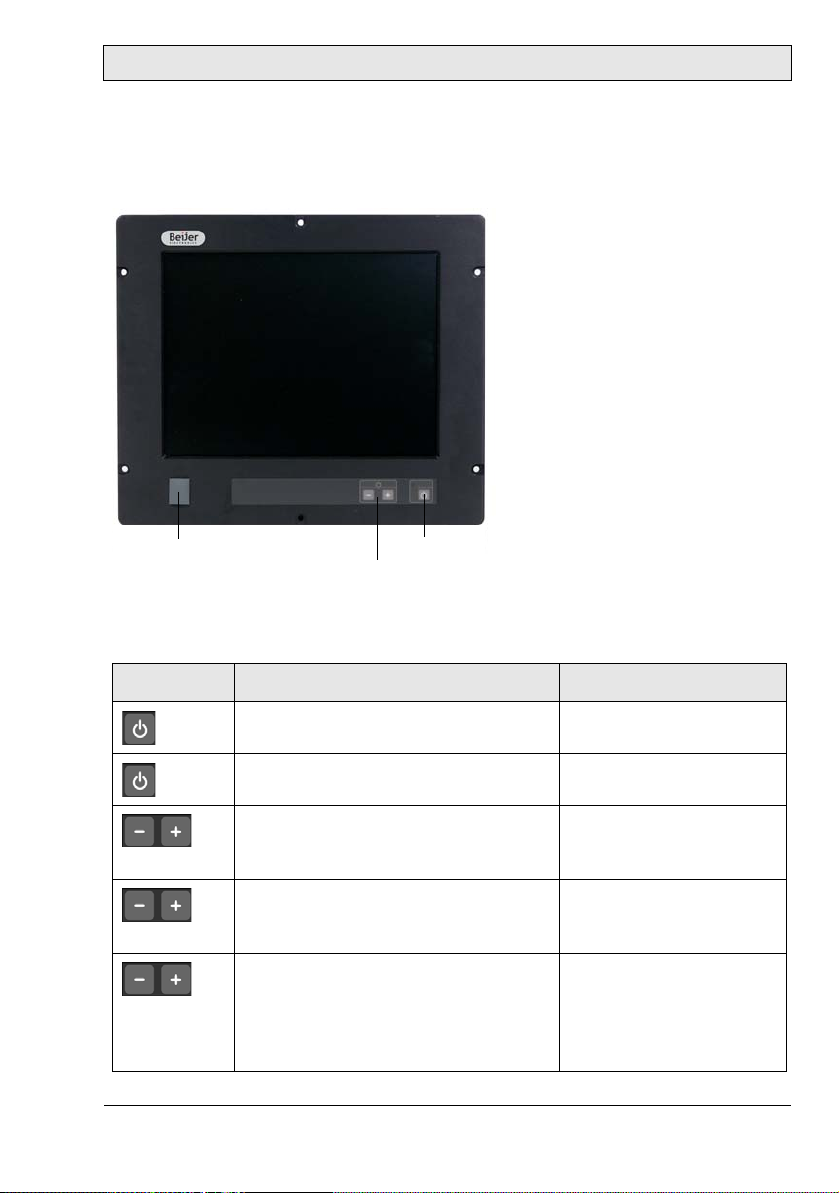
Description of Parts
USB port
Dimmer buttons
Power button
5Description of Parts
Monitor sizes 15", 17"and 19" are available.
The front includes a USB-port under hatch, a power button with a LED, and a
set of dimmer buttons. The buttons are explained below:
Button Instruction Description
Press the power button for more than
one second
Press the power button for more than
one second
Press - (brightness down) on the dimmer button (single step or automatic
repeating after one second)
Press + (brightness up) on the dimmer
button (single step or automatic
repeating after one second)
Press + and - simultaneously for more
than one second
Turns the monitor off
Turns the monitor on
Makes the display darker
Makes the display brighter
Tu rn s on fu ll b rightness
quickly (default - this may
be configured according
to RBC software manual
MAEN986)
Beijer Electronics, MAEN983B 13
Page 14
Description of Parts
LED Description
The power LED can assume the following statuses in monitors with Ethernet:
LED Description
Green Normal operation
- The monitor is turned off
The power LED can assume the following statuses in monitors without Ethernet:
LED Description
Green Signal detected – normal operation
Blinking green/orange Resolution out of range
Orange No input signal availa ble
Blinking orange No input cable or signal detected
Red Display refresh rate out of range
14 Beijer Electronics, MAEN983B
Page 15
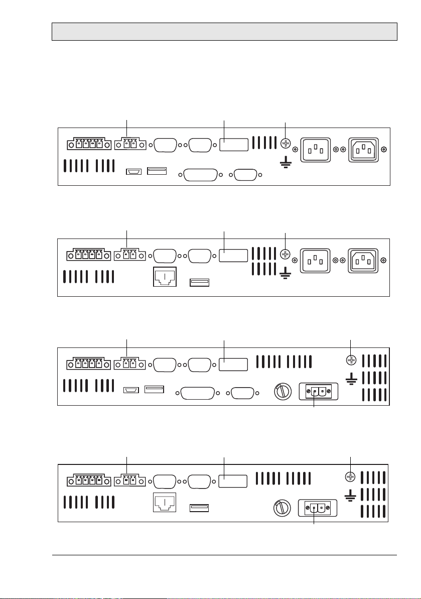
Description of Parts
Power remote
DVI VGA
USB
Power
Buzzer in/out
AC out
Power
Mini USB
COM A COM B
DIP
switches
Earth screw
AC in
Power remote
USB
Power
Buzzer in/out
AC out
Power
Ethernet
COM A COM B
DIP
switches
Earth screw
AC in
Power remote
Power DC
Buzzer in/out
Fuse
COM A COM B
DIP
switches
Earth screw
Mini USB USB
DVI VGA
Power remote
USB
Power DC
Buzzer in/out
Fuse
Ethernet
COM A COM B
DIP
switches
Earth screw
5.1 Communication Ports
Communication Ports 230 V AC without Ethernet
1
1
4 2
ON
51
OFF
Communication Ports 230 V AC with Ethernet
1
1
4 2
ON
51
OFF
Communication Ports 24 V DC without Ethernet
1
1
4 2
OFF
ON
51
0 V +24 V
Communication Ports 24 V DC with Ethernet
1
1
4 2
Beijer Electronics, MAEN983B 15
ON
51
OFF
0 V +24 V
Page 16

Description of Parts
5.2 Assembly
A free space of 100 mm, for air circulation, has to be provided around the appliance, to dissipate the heat generated during operation.
The monitor is assembled with hexagon nuts (included in the supplied mounting kit).
Note:
Possible risk of damage to the appliance!
Protectio n class IP65 for the front panel i s only guaranteed with a perf ect fitting seal.
Pay attenti on to the to rque when fi xi ng the fr o nt pa nel .
5.3 Power Supply
The MTe Nautic monitors are available with 230 V AC or 24 V DC power system.
The power supply for 24 V DC is carried out via a double-pole connector
(Phoenix MST BT 2,5/2).
The monitors are certified for the connection to protective grounded power supply according to EN60950. The controlling transformer has to comply with
EN60742.
Note:
Check the power supply system with the relevant data on the type plate.
16 Beijer Electronics, MAEN983B
Page 17
Description of Parts
5.4 Earthing System
The following items have to be observed to guarantee a safe dissipation of electronic interference:
– Appliance and switch board have to be connected to the nearest possible cen-
tral earthing point.
– Make sure of a possibly low inductive connection between appliance and
switch board.
– All data cables connected to the appliance have to be of the shield type.
– The screens have to be earthed on both sides. A low ohm connection between
the connected systems is essential. Avoid high equalizing currents through the
cable screen due to voltage fluctuations.
– The earthing connection is to be carried out with min. 4 mm² cross section.
5.5 Buzzer In/Out
There is a buzzer integrated in the front behind the front foil. The buzzer can be
activated with a Beijer Electronics RBC software command or with a buzzer-in
signal. Buzzer-out is a relay contact parallel to the integrated buzzer that can be
used to switch an external signal device.
The buzzer-in and -out can be connected to the 4-pole Phoenix connector:
Buzzer Connection Comment
Buzzer-out P in 1 and pin 2 NO-contact, max. load 1 A @ 24 V DC
Buzzer-in Pin 3 + 24 V DC / pin 4 ground
Please see the RBC software manual MAEN986 for further information.
Beijer Electronics, MAEN983B 17
Page 18

Description of Parts
5.6 Remote Power Out
Remote power out is a relay contact that is closed after the power button on the
front side is pressed for more than one second. It is opened after the button is
released. With the remote power out signal, it is possible to switch an external
Beijer Electronics EPC Nautic on and off. The EPC has a corresponding ATX
power remote input. To use this function, connect the double-pole Phoenix connector to the corresponding connector on the EPC.
5.7 AC Power Out
The AC power out terminal on the 230 V AC-models is internally connected to
the AC power in terminal through a double-pole relay. This makes it possible to
connect an external AC powered device such as a PC (max. 6 A). The AC power
out is active only when the monitor is on.
18 Beijer Electronics, MAEN983B
Page 19

Operation
6Operation
6.1 Touch Screen Installation
Perform the SETUP.EXE under:
–CD-ROM: \MTe_Nautic_Monitors\Driver\Touch\UniWinDriver631a.
Beijer Electronics, MAEN983B 19
Page 20

Operation
1. Follow the instructions on the screen and press Next.
2. Accept the license provisions.
20 Beijer Electronics, MAEN983B
Page 21

3. Select Autodetect or manually select the technical connection data.
Operation
Beijer Electronics, MAEN983B 21
Page 22

Operation
4. Press Finish and follow the instructions for a re-start.
5. After a re-start of the operating system you will find Hampshire Control
Panel among the programs.
6. Calibrate the touch screen with your finger or with a rounded pointed
touch pen.
22 Beijer Electronics, MAEN983B
Page 23

Operation
6.2 On Screen Display Menu
Note:
The On Screen Display menu is supported only for monitors without an Ethernet
connection.
BUTTON
SOURCE
ESC
ENTER
RIGHT
UP
DOWN
LEFT
ON / OFF
STATUS LED
The On Screen Display (OSD) menu is controlled via the
OSD buttons.
It is opened by the Enter button.
The following controls are available for selection from the
OSD menu: Input Selection, Brightness Control, Color
Control, Image Adjustment and To o l s .
6.2.1 OSD Functionality
The following table describes differences in keypad functions with and without
activating OSD:
Key Function - OSD active Functio n - OS D no t active
POWER Switch power on/off Switch power on/off
LEFT Decrease Value Decrease Value
RIGHT Increase Value Increase Value
UP Not used Scroll up (Esc)
DOWN Shortcut black level and brightness con-
trol
ESCape Not used Escape
ENTER Enter Enter
SOURCE Toggle Input Source ----
Scroll down (Enter)
For a description of the power LED, see section LED Description .
Beijer Electronics, MAEN983B 23
Page 24

Operation
6.2.2 System Messages
The following system messages may be displayed:
System message Description
The system is booting up.
There is no signal at DVI or RGB input.
Reason: PC is off or in sleep mode or cable is not connected to graphics card
There is no cable connected to the RGB input.
There is no cable connected to the DVI input.
There is no cable connected to the USB input.
Provided signal/resolution at DVI or RGB input is not
supported.
6.2.3 Input Selection Menu
Press Enter or down to enter the Input
Selection menu.
Use left or right buttons to select RGB Analog, DVI or UGA (USB) input.
Select Exit or up to return to the icon bar.
24 Beijer Electronics, MAEN983B
Page 25

6.2.4 Brightness Control Menu
Press Enter or down to enter the Brightness
Control menu.
Use left or right buttons to adjust Blacklevel
& Brightness, Contrast or Blacklevel.
Select Exit or up to return to the icon bar.
Blacklevel & Brightness
Use left or right buttons to decrease or
increase panel brightness.
• Blacklevel adjustment: 0-128
• Brightness adjustment: 128-256
Press Enter or down to confirm, or Esc to
cancel.
Operation
Contrast
Use left or right buttons to decrease or
increase display contrast.
Press Enter or down to confirm, or Esc to
cancel.
Beijer Electronics, MAEN983B 25
Page 26

Operation
Blacklevel
Use up or down buttons to select red, green
or blue.
Use left or right buttons to decrease or
increase the selected color value.
Press Enter or down to confirm, or Esc to
cancel.
6.2.5 Color Control Menu
Press Enter or down to enter the Color
Control menu.
Use left or right buttons to adjust Color
Auto-adjust, Color or Color Temperature.
Select Exit or up to return to the icon bar.
Note:
Color Auto-adjust is availab le only if RGB analog is se l ected
as input. This func t ion adjusts the analog input in t e rface to
the used graphic board. The result has to be confirmed by
selecting either Yes or No using the left or right buttons.
26 Beijer Electronics, MAEN983B
Page 27

Color
Color Temperature
Operation
Press Enter or down to enter the Color
menu.
Use left or right buttons to select a value, or
to enter the Color Temperature panel.
• Color Temperature panel
• 4200K
• 5000K
• 6500K
• 9300K
Select Exit or up to return to the icon bar.
Use up or down buttons to select red, green
or blue.
Use left or right buttons to decrease or
increase the selected color value.
Press Enter or down to confirm, or Esc to
cancel.
Beijer Electronics, MAEN983B 27
Page 28

Operation
6.2.6 Image Adjustment Menu
The Image Adjustment settings are available only if RGB analog is selected as
input.
Press Enter or down to enter the Image
Adjustment menu.
Use left or right buttons to select Image
Auto-adjust, Horizontal Width, Phase,
Horizontal Position or Ve rti ca l Pos iti on.
Press Enter or down to confirm.
Select Exit or up to return to the icon bar.
Note:
Image Auto-adjust is availab l e on l y if RGB analog is select e d
as input. This function adj usts the image on the d isplay including phase and horizontal/vertical position. The r es u lt h as to
be confirmed by selecting either Yes or No using the left or
right buttons.
Horizontal Width
Use left or right buttons to adjust the image
size manually.
Press Enter or down to confirm, or Esc to
cancel.
28 Beijer Electronics, MAEN983B
Page 29

Phase
Horizontal Position
Operation
Use left or right buttons to adjust the phase
manually.
Press Enter or down to confirm, or Esc to
cancel.
Use left or right buttons to adjust the
position manually.
Press Enter or down to confirm, or Esc to
cancel.
Vertical Position
Use left or right buttons to adjust the
position manually.
Press Enter or down to confirm, or Esc to
cancel.
Beijer Electronics, MAEN983B 29
Page 30

Operation
6.2.7 Tools Menu
Factory Default Settings
Reset complete factory default settings
Reset color factory default settings
Press Enter or down to enter the Tools
menu.
Use left or right buttons to select one of the
factory default settings Complete Reset,
Color Reset or Image Reset.
Press Enter or down to confirm.
Select Exit or up to return to the icon bar.
Reset image factory default settings
6.2.8 Exit
Use left or right buttons to select Exit.
Press Enter to save changes and close OSD.
30 Beijer Electronics, MAEN983B
Page 31

Operation
6.3 USB Graphic Driver
The monitor can be configured either to mirror your primary screen, or to extend Windows. The USB to VGA driver used to control the extra screens uses
little PC resource and offers a vast array of screen resolutions and color depths.
6.3.1 System Requirements
The d.client USB software can be installed on any desktop or laptop PC running
one of the following operating systems:
Operating system Service pack/driver requirement
Windows XP Home Service Pack 2 and 3
Windows XP Professional Service Pack 2 and 3
Windows 2000 Service Pack 4
Windows Vista Basic Driver revision 4.3 or higher
Windows Vista Aero Driver revision 4.3 or higher
Up to six monitors configured as d.client USB units can be connected to the PC
at a time.
Beijer Electronics, MAEN983B 31
Page 32

Operation
6.3.2 Software Installation
The following example is for Windows XP - there are some differences in terminology and user interface on Windows 2000/Vista, but the basic steps are the
same. You can select to first connect the monitor to the PC, or to first install the
software and then connect the monitor.
Installation of Connected Hardware
With this method, the monitor is connected prior to installing the drivers.
1. Insert the software installation CD, or if your software was downloaded,
unzip it to a convenient folder.
2. Connect the monitor to the PC via USB. When the Found New Hardware
Wizard starts, follow its instructions:
3. Select No, not this time.
32 Beijer Electronics, MAEN983B
Page 33

Operation
4. Select Install from a list or a specific location (Advanced), and point the
wizard at the software.
Beijer Electronics, MAEN983B 33
Page 34

Operation
Installation without Connected Hardware
With this method, the drivers are installed before connecting the monitor to the
PC.
1. Navigate to the d.client USB installation directory on your PC or CD and
double-click on Setup.exe to start installing the drivers.
2. Once the drivers are installed, connect the monitor to the PC via USB. The
PC will automatically detect the new USB device and start the Found New
Hardware Wizard. Follow the instructions of the wizard:
3. Select No, not this time.
34 Beijer Electronics, MAEN983B
Page 35

4. Select Install the software automatically (Recommended).
Operation
Beijer Electronics, MAEN983B 35
Page 36

Operation
6.3.3 Uninstalling the Graphics Software
The d.client USB software can be removed using the Add or Remove Programs
utility in Windows control panel. In Windows Vista this is called Programs and
Features.
1. Open Add or Remove Programs.
2. Locate the d.client USB entry and click Remove.
3. Click Yes to confirm that you want to remove it.
The software will then uninstall automatically.
36 Beijer Electronics, MAEN983B
Page 37

Operation
6.3.4 Using the Software
The behavior of the d.client USB software is configured through Windows Display Properties dialog box.
1. To access the Display Properties dialog, right-click on the desktop and
select Properties.
2. Select the Settings tab.
3. Locate d.client USB in the Display drop-down list. Its mode, resolution,
color quality and position can all be controlled from here.
Beijer Electronics, MAEN983B 37
Page 38

Operation
Setting the Display in Extended Mode
In extended mode, the d.client USB forms part of the extended Windows desktop.
1. To set the display in this mode, check the Extend my Windows desktop
onto this monitor box (marked 1 in previous figure).
2. Configure screen resolution and color quality using the appropriate controls
(2 and 3), and arrange its position with respect to the other monitors on the
extended desktop in using the drag area (4).
3. For more detailed mode settings, including the refresh rate, click on the
Advanced button, then the Adapter tab and finally the List all modes…
button. All valid combinations of resolution, color quality and refresh rate
are listed.
Setting the Display in Mirror Mode
In mirror mode, the d.client USB simply copies what is on the main (primary)
display.
1. To set the display in this mode, uncheck the Extend my Windows desktop
onto this monitor box (marked 1 in previous figure).
The resolution, color depth and refresh rate of the primary screen are replicated
on the d.client USB.
If the d.client USB display unit supports a lower resolution than the primary display, the on board scaling engine will downscale the image to the native panel
resolution.
Setting the Display as the Primary Display
To make the d.client USB unit the primary display, check the Use this device as
the primary monitor (marked 1 in previous figure). On some PCs it is necessary
to disable the main display (i.e. unchecking the box marked Extend my Windows desktop onto this monitor for the main display) as part of the same set-
tings change. The d.client USB display stays primary if the PC enters hibernate
or suspend mode or is rebooted. If the d.client is detached, the main display becomes primary again.
38 Beijer Electronics, MAEN983B
Page 39

Operation
6.3.5 Controlling the Display
The d.client unit can also be configured from the d.client Icon application.
When devices are attached, an icon in the notification area indicates that the
program is running. Clicking on it displays a menu to control attached devices:
The menu contains many of the settings that can be configured via Windows
Display Properties, in addition to some other settings:
Menu item Description
Screen Rotation Rotates Windows desktop (90, 180 or 270 degrees)
Extend To Chang es the dev ice to extende d mode, a nd places i t to the
left of/right of/above/below the primary monitor
Off Switches the disp lay off on an adapter
Advanced Opens the Windows Display Properties dialog
Beijer Electronics, MAEN983B 39
Page 40

Operation
6.3.6 General Characteristics
Standby and Hibernate, Shut Down and Restart
If the PC that the d.client USB is connected to is set in standby or hibernate
mode, the display goes blank. When the PC is powered up again (and unlocked
if necessary), the connected display returns to the same mode as before standby
or hibernation.
If the PC is shut down, restarted and logged in to, the connected display returns
to the same mode as before shutdown.
d.client USB with Multiple Users
d.client USB work with multiple users on the PC. The mode settings are saved
for each user, thus allowing individual desktop configuration.
Disconnecting the d.client USB
If the d.client USB is powered off or the USB cable is removed from the PC, the
display goes blank. All windows and icons move to the primary screen. On reconnection or powering up of the d.client USB, the display returns to the same
mode as before disconnection.
However, windows and icons that were previously on the screen will not be
moved back.
40 Beijer Electronics, MAEN983B
Page 41

Operation
6.4 USB Server Driver
6.4.1 Software Installation
Note:
The USB Server driver is supported only for monitors with an Ethernet connection.
The default IP address of the monitor is 192.168.0.1; the default subnet mask is
255.255.255.0.
1. Navigate to the USB server installation directory MTe_Nautic_Monitors\
Driver\USB_Server_Driver on your PC or CD and double-click on the
USB Server setup file to start the installation.
The installation starts automatically.
2. Click Finish when the installation is complete.
Beijer Electronics, MAEN983B 41
Page 42

Operation
6.4.2 Using the Software
The USB Server program starts automatically in the background. An icon in the
notification area indicates that the program is running.
If you have disabled the autostart option, double-click on the Launch USB
Server shortcut on the desktop to start running the program in the background.
Main Menu
Right-click on the USB Server icon in the notification area and select Open Display Solution USB Server to display the main menu.
42 Beijer Electronics, MAEN983B
Page 43

Operation
Status of USB Servers and Devices
The tree view displays the status of all USB servers and devices that you can access. A USB Server is either accessible or inaccessible. An inaccessible server is
either disconnected from the network, powered off or suffers other technical difficulties that prevent it from being accessed by your PC. An inaccessible server
will not show up on the tree view.
Each status is represented by an icon of different color:
Color Status Comment
Green Ready The device is unoccupied and ready for connection
Orange Connected Connection established
Red Occupied by
Others with Error
Beijer Electronics, MAEN983B 43
A problem has occurred for the device that is occupied by another user
Page 44

Operation
It is also p ossib le to s ee al l con nected devic es by right- clicki ng o n the U SB Ser ver
icon in the notification area and selecting Connect.
Right-clicking on a device in the tree view, and selecting Details, displays additional information about the selected device:
Manual Disconnect and Connect
You can disconnect or connect to a device manually, by clicking on its icon in
the tree view.
44 Beijer Electronics, MAEN983B
Page 45

Operation
Exit Program
The program is stopped by right-clicking on the USB Server icon in the notification area and selecting Exit.
This will shut down the server. If devices are connected, you must confirm disconnecting them.
Beijer Electronics, MAEN983B 45
Page 46

Operation
6.5 Dimming
The monitor can be dimmed in different ways:
– Local, using the dimmer buttons on the front panel
– Remote, using the serial port, a USB port or Ethernet
Please see the RBC software manual MAEN986 for further information about
remote dimming.
6.6 Cable Fixing Points
When connecting interface cables such as RS232, USB, LAN or VGA, the cables must be fixed at the cable fixing points, to avoid that the cables loosen because of vibrations.
46 Beijer Electronics, MAEN983B
Page 47

Te ch n ic a l D a t a
7 Technical Data
Please see chapter 2 Product Naming for a description of how products are
named.
MTe 150 Nautic
Parameter
Size, W x H x D 412 x 351 x 81 mm 430 x 390 x 81 mm 483.2 x 444 x 81 mm
Mounting depth 80 mm
Front panel seal IP65
Rear panel seal IP20
Weight 6.5 kg 7.5 kg 10.0 kg
USB port 1 x USB 2.0 on front side behind hatch
Graphic port VGA/DVI/USB or Ethernet
Power c onsump-
tion at rated
voltage
Fuse 1 AT (230 V AC) / 4 AT (24 V DC)
Power s upply
options
Active area of
display
Pixels 1024 x 768 1280 x 1024 1280 x 1024
Pixel pitch (RGB) 0.297 x 0.297 mm 0.264 x 0.264 mm 0.294 x 0.294 mm
Max. number of
colors
View angle (up/
down/left/right)
(typical)
MTe T150 Nautic
MTe 150 E Nautic
MTe T150 E Nautic
(130 mm including clearance)
1 x USB 2.0 on back side
45 W
115-230 V AC ± 15%. 1 A max (switch on peak 30 A).
24 V DC ± 15%. 2.4 A max (switch on peak 12 A).
304.1 x 228.1 mm 337.9 x 270.3 mm 376.3 x 301.1 mm
16.7 million
50/60/75/75 ° 89/89/89/89 °
MTe 170 Nautic
MTe T170 Nautic
MTe 170 E Nautic
MTe T170 E Nautic
MTe 190 Nautic
MTe T190 Nautic
MTe 190 E Nautic
MTe T190 E Nautic
Beijer Electronics, MAEN983B 47
Page 48

Technical Data
MTe 150 Nautic
Parameter
Light intensity
(typical)
Contrast ratio 450:1 1500:1 1000:1
Response time 6 ms / 19 ms 15 ms / 10 ms 13 ms / 7 ms
Display technol-
ogy
Touch screen
technology
Touch screen
resolution
Supported signal
resolution
Ambient temper-
ature
Relative ambi-
ent humidity
Storage temper-
ature
Relative storage
humidity
Basic RBC soft-
ware version
* Only applies to MTe T150/T170/T190 Nautic and MTe T150/T170/T190 E Nautic
MTe T150 Nautic
MTe 150 E Nautic
MTe T150 E Nautic
250 cd/m
TN PVA SPVA
Resistive*
4096 x 4096 points*
640 x 480 to 1600 x 1200
-15 ° to +55 °C
30% to 90% non-condensed
-20 ° to +70 °C
10% to 90% non-condensed
V0003 May 28, 2009
Please contact Beijer Electronics/Elektronik-Systeme Lauer for
information about current version.
2
MTe 170 Nautic
MTe T170 Nautic
MTe 170 E Nautic
MTe T170 E Nautic
MTe 190 Nautic
MTe T190 Nautic
MTe 190 E Nautic
MTe T190 E Nautic
48 Beijer Electronics, MAEN983B
Page 49

Drawings
8 Drawings
8.1 MTe 150/T150 Nautic Front View
412
206
351
222
64.5
394
6 x hole Ø 6.5
R10
Beijer Electronics, MAEN983B 49
Page 50

Drawings
222
333
197
394
6 x holes Ø 6.5 mm
369+1 0
324
+1
0
55.5
197
8.2 MTe 150/T150 Nautic Cut Out Drawing
Cut out dimensions: 369.0 x 324.0 mm, tolerance +1 mm. 15 mm is required
for mounting screws on all sides = 399.0 x 354.0 mm.
Front plate dimensions: 412.0 x 351.0, tolerance ±0.2 mm.
Mounting method: 6 x M6x25 steel screws DIN 6912. Screws and o-ring seals
are included.
Max. 8 mm thick mounting frame.
50 Beijer Electronics, MAEN983B
Page 51

8.3 MTe 150/T150 Nautic Outline
24.5
31
41
371
381
387.5
R3
15" MDD/Z300
19.5
333
12
Drawings
Bottom view
Rear view Side view
R10
15" MDD/Z300
Drawings
Beijer Electronics, MAEN983B 51
Page 52

Drawings
8.4 MTe 170/T170 Nautic Front V iew
430
414
200
390
180
8 x holes Ø 6.5 mm
105
R10
52 Beijer Electronics, MAEN983B
Page 53

Drawings
8.5 MTe 170/T170 Nautic Cut Out Drawing
Cut out dimensions: 396.0 x 364.0 mm, tolerance +1 mm. 15 mm is required
for mounting screws on all sides = 426.0 x 394.0 mm
374
180
+1
0
364
8 x holes Ø 6.5 mm
92
200
396+1 0
414
Front plate dimensions: 430.0 x 390.0, tolerance ±0.2 mm.
Mounting method: 8 x M6x25 steel screws DIN 6912. Screws and o-ring seals
are included.
Max. 8 mm thick mounting frame.
Beijer Electronics, MAEN983B 53
Page 54

Drawings
17 Zoll MDD/Z301
17 Zoll FP 17/Z200
8.6 MTe 170/T170 Nautic Outline Drawings
Bottom view
412
390
50
40
18
Rear view Side view
380
R3
17 Zoll MDD/Z301
17 Zoll FP 17/Z200
R10
353
37
15
12
54 Beijer Electronics, MAEN983B
Page 55

Drawings
Frontplatte Nautic FP_19/Z200
8.7 MTe 190/T190 Nautic Front View
R10
Frontplatte Nautic FP_19/Z200
104.6
235
444
104.4
126.6
230
483.2
126.6
Beijer Electronics, MAEN983B 55
Page 56

Drawings
8.8 MTe 190/T190 Nautic Cut Out Drawing
Cut out dimensions: 438.0 x 416.0 mm, tolerance +1 mm. 15 mm is required
for mounting screws on all sides = 468.0 x 446.0 mm
235
+1
0
416
426
8 x holes Ø 6.5 mm
90.4
230
438+1 0
465.2
Front plate dimensions: 483.2 x 444.0, tolerance ±0.2 mm.
Mounting method: 8 x M6x25 steel screws DIN 6912. Screws and o-ring seals
are included.
Max. 8 mm thick mounting frame.
56 Beijer Electronics, MAEN983B
Page 57

Drawings
19 Zoll Nautic MDD/Z302
MDD/Z310_19 Zoll
19 Zoll Nautic FP 19/Z200
8.9 MTe 190/T190 Nautic Outline Drawings
Bottom view
458.1
416.6
76.6
66.6
25.1
12
Rear view Side view
19 Zoll Nautic FP 19/Z200
406.6
R3
R10
19 Zoll Nautic MDD/Z302
MDD/Z310_19 Zoll
411
Mounting method: 8 x M6x25 V2A-screws DIN 6912. Screws and o-ring seals
are included.
Beijer Electronics, MAEN983B 57
Page 58

Head Office
Sweden
Beijer Electronics Products AB
Box 426
201 24 Malmö, SWEDEN
Tel: +46 40 35 86 00
Fax: +46 40 93 23 01
info@beijerelectronics.com
Subsidiaries
Germany
Elektronik-Systeme Lauer GmbH & Co. KG
Kelterstraße 59
72669 Unterensingen, GERMANY
Tel.: +49 70 22/96 60 0
Fax: +49 70 22/96 60-103
info@lauer-hmi.com
USA
Beijer Electronics Inc.
939 N. Plum Grove Road, Suite F
Schaumburg, IL 601 73, USA
Tel: +1 847 619 6068
Fax: +1 847 619 6674
info.usa@beijerelectronics.com
China
Beijer Electronics Co. Ltd
Room 201, Buildning B, No. 1618,
Yishan Road, Shanghai 201103, CHINA
Tel: +86 21 6145 0400
Fax: +86 21 6145 0499
info@beijerelectronics.cn
Taiw an
Beijer Electronics Corp.
7 & 8 F, No. 108 Minquan Rd.
Xindian City, Taipei County, TAIWAN
23141
Tel: +886-2-2218-3600
Fax: +886-2-2218-9547
info.tw@beijerelectronics.com
 Loading...