

Page 1

MAEN956, 2008-09
MT 230 Nautic Monitor
Installation Manual
English
Page 2

Foreword
MT 230 Nautic Monitor Installation Manual
Foreword
The MT 230 Nautic Monitor affords an excellent quality display of nautical
charts or machine data. It features non-reflective glass for easy daylight viewing
and offers infinitely adjustable dimming while delivering the specific functions
such as ECDIS/RADAR compliance to enable automation and navigational
tasks.
With shallow depth for easy installation, the MT 230 Nautic Monitor can be
utilized in combination with the EPC-box Nautic or third party computers.
This manual describes the MT 230 Nautic Monitor and gives instructions on
installation, operation and service.
© Beijer Electronics AB, MAEN956, 2008-09
Please read the entire installation manual prior to installing and using this equipment. Only qualified
personnel may install, operate or repair this equipment. Beijer Electronics AB is not responsible for
modified, altered or renovated equipment. Because the equipment has a wide range of applications, users
must acquire the appropriate knowledge to use the equipment properly in their specific applications.
Persons responsible for the application and the equipment must themselves ensure that each application
is in compliance with all relevant requirements, standards and legislation in respect to configuration and
safety. Only parts and accessories manufactured according to specifications set by Beijer Electronics AB
may be used.
BEIJER ELECTRONICS AB SHALL NOT BE LIABLE TO ANYONE FOR ANY DIRECT,
INDIRECT, SPECIAL, INCIDENTAL OR CONSEQUENTIAL DAMAGES RESULTING FROM
THE INSTALLATION, USE OR REPAIR OF THIS EQUIPMENT, WHETHER ARISING IN
TORT, CONTRACT, OR OTHERWISE. BUYER'S SOLE REMEDY SHALL BE THE REPAIR,
REPLACEMENT, OR REFUND OF PURCHASE PRICE, AND THE CHOICE OF THE APPLICABLE REMEDY SHALL BE AT THE SOLE DISCRETION OF BEIJER ELECTRONICS AB.
Beijer Electronics, MAEN956
Page 3

Contents
Contents
1 Safety Precautions................................................................................... 5
1.1 Nautic Approvals and Certificates .......................................................5
1.2 General ...............................................................................................6
1.3 During Installation..............................................................................7
1.4 During Use .........................................................................................7
1.5 Service and Maintenance.....................................................................8
1.6 Dismantling and Scrapping.................................................................8
2 Technical Introduction ........................................................................... 9
3 Supplied Equipment ............................................................................. 10
4 Description of Parts.............................................................................. 11
5 Quick OSD Menu ................................................................................ 12
6 OSD Menu........................................................................................... 13
7 Picture in Picture Possibilities .............................................................. 23
8 Dimming .............................................................................................. 24
9 Interfaces and Functions ....................................................................... 25
9.1 Composite Video ..............................................................................26
9.2 S-Video .............................................................................................27
9.3 VGA .................................................................................................28
9.4 DVI ..................................................................................................30
9.5 Serial Interfaces .................................................................................32
9.6 LAN/Ethernet (RJ45) .......................................................................34
9.7 USB ..................................................................................................36
9.8 Analog IN .........................................................................................37
9.9 Digital IN .........................................................................................38
9.10 Digital OUT.....................................................................................39
9.11 Remote Power...................................................................................40
Beijer Electronics, MAEN956
Page 4

Contents
10 DIP Switches ........................................................................................ 41
11 Power Supply........................................................................................ 42
11.1 Protected Ground..............................................................................42
12 Technical Data ..................................................................................... 43
13 Drawings .............................................................................................. 45
13.1 Front View ........................................................................................45
13.2 Cut Out Drawing..............................................................................46
13.3 Mounting Drawing ...........................................................................47
13.4 Outline Drawings..............................................................................48
Beijer Electronics, MAEN956
Page 5

Safety Precautions
1 Safety Precautions
Both the installer and the owner and/or operator of the monitor must read and
understand this installation manual.
1.1 Nautic Approvals and Certificates
The MT 230 conforms with the following stated standards:
– EMC Directive 2004/108/EC; Emission EN 61000-6-4:2007;
Immunity EN 61000-6-2: 2005
– Conformance test for use as ECDIS monitor according to IEC 61174,
Edition 2 and IEC 60945, Edition 4
Note:
Complete certification for ECDI S can be made only with complete system and
navigation software.
Beijer Electronics, MAEN956 5
Page 6

Safety Precautions
1.2 General
– Read the safety precautions carefully.
– Check the delivery for transportation damage. If damage is found, notify the
supplier as soon as possible.
– Do not use the monitor in an environment with high explosive hazards.
– The supplier is not responsible for modified, altered or reconstructed equip-
ment.
– Use only parts and accessories manufactured according to specifications of the
supplier.
– Read the installation and operating instructions carefully before installing, us-
ing or repairing the monitor.
– Never allow fluids, metal filings or wiring debris to enter any openings in the
monitor. This may cause fire or electrical shock.
– Only qualified personnel may operate the monitor.
– Storing the monitor where the temperature is lower/higher than recommend-
ed in this manual can cause the LCD display liquid to congeal/become isotopic.
– The LCD display liquid contains a powerful irritant. In case of skin contact,
wash immediately with plenty of water. In case of eye contact, hold the eye
open, flush with plenty of water and get medical attention.
– The figures in this manual serves an illustrative purpose. Because of the many
variables associated with any particular installation, the supplier cannot assume responsibility for actual use based on the figures.
– The supplier neither guarantees that the monitor is suitable for your particu-
lar application, nor assumes responsibility for your product design, installation or operation.
6 Beijer Electronics, MAEN956
Page 7

Safety Precautions
1.3 During Installation
– The monitor is designed for stationary installation on a plane surface, where
the following conditions are fulfilled:
• no high explosive risks
• no strong magnetic fields
• no direct sunlight
• no large, sudden temperature changes
– Install the monitor according to the accompanying installation instructions.
– Ground the monitor according to the accompanying installation instruc-
tions.
– Only qualified personnel may install the monitor.
– Separate the high voltage, signal and supply cables.
– Make sure that the voltage and polarity of the power source is correct before
connecting the monitor to the power outlet.
– Peripheral equipment must be appropriate for the application and location.
– The controlling transformer has to comply with EN60742.
1.4 During Use
– Keep the monitor clean.
– Emergency stop and other safety functions may not be controlled from the
monitor.
– Do not use too much force or sharp objects when touching the keys, touch
screen etc.
Beijer Electronics, MAEN956 7
Page 8

Safety Precautions
1.5 Service and Maintenance
– Only qualified personnel should carry out repairs.
– The agreed warranty applies.
– Before carrying out any cleaning or maintenance operations, disconnect the
equipment from the electrical supply.
– Clean the display and surrounding front cover with a soft cloth and mild de-
tergent.
– Replacing the battery incorrectly may result in explosion. Only use batteries
recommended by the supplier.
1.6 Dismantling and Scrapping
– The monitor or parts thereof shall be recycled according to local regulations.
– The following components contain substances that might be hazardous to
health and the environment: lithium battery, electrolytic capacitor and display.
8 Beijer Electronics, MAEN956
Page 9

Technical Introduction
2 Technical Introduction
The MT 230 Nautic Monitor has a multiple interfaces and coupling possibilities.
Multiple dimming possibilities distinguishes the monitor.
Several video sources allows using Picture in Picture (split screen) as well as other
advanced video functions.
Cross-linking monitors as well as programming and control over serial network
or LAN is possible.
The USB front interface and a USB 2.0 hub permits attaching devices directly
to the monitor.
Analog and digital in- and outputs for several control functions such as dimming
or simultaneously switching power on/off the monitor and the PC, complete the
comprehensive functions.
This manual describes functions, settings, menus, interfaces as well as programming of the monitor. Please read safety precautions, appropriate chapters and
user references before putting the monitor into operation.
Beijer Electronics, MAEN956 9
Page 10

Supplied Equipment
3 Supplied Equipment
Part Description
CD; driver software Driver software CD
Installation manual This manual describes specif ic information about
Beijer Electronics pr o duc ts onl y – no t abo u t t hir d
party components.
Power cable 3 meters
DVI cable 3 meters
VGA cable 3 meters
Serial RS232 cable 3 meters
USB cable 3 meters
Ethernet cross patch cable 3 meters
Mounting kit 8 x M6x25 screws, including nuts, rubber seals and
wave discs
10 Beijer Electronics, MAEN956
Page 11
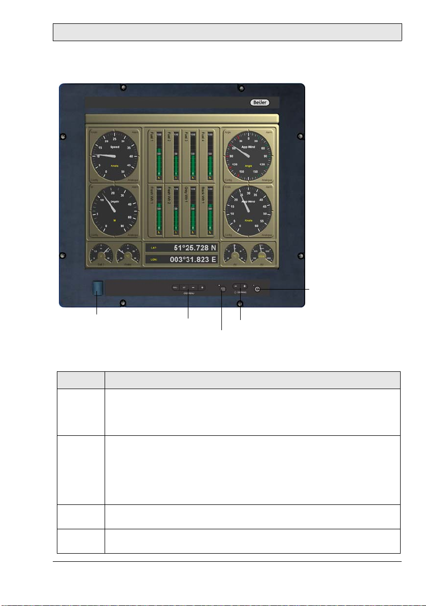
4 Description of Parts
Description of Parts
Power button
USB port
OSD menu
buttons
Dimmer button
ECDIS key
The buttons on the front are explained below:
Button Instruction
OSD menu Press the + or the SET button to open the Quick OSD Menu to make
basic settings.
Press the MENU button to open the full OSD Me n u to make advanced
settings.
ECDIS key With the ECDIS key the brightness as w ell as the c olors a re set o n a cer -
tain default value. The LED is lit when ECDIS mode is on.
Note:
If the ECDIS key is activated (LED on) all other key s (d im m e r, OSD) are
inactivated and cannot be operated. Additionally , no commands and/or
programming over the serial and/or Ethernet interface can be made.
Dimmer
button
Power
button
Beijer Electronics, MAEN956 11
Press the - button to decrease th e contrast.
Press the + button to increase the contrast.
Press the button to turn the monitor on/off without disconnecting the
power supply. The LED is lit when the monitor is on.
Page 12
Quick OSD Menu
5Quick OSD Menu
Press the SET or the + button among the OSD (On Screen Display) menu buttons to make basic settings from the Quick OSD menu. Then use the buttons
for the following functions:
Button Function Explanation
MENU No function in the Quick OSD menu
SET Opens the Quick OSD
menu to adjust contrast, brightness, zoom
and split screen
+Opens the Quick OSD
menu to select input
source or to perform an
automatic screen alignment
Increases values
- Decreases values
Brightness adjustment range: 0-100
Contrast adjustment range: 0-100
Zoom adjustment range: 0-100
Zoom for split screen window is available
from submenu.
Selection for split screen size (PIP): small,
medium or large
Select RGB1, RGB2, Digital, FBAS or S-video
using SET for navigation and + for selection.
Press + again to perform an automatic
screen alignment including frequency, phase
and pictur e position .
12 Beijer Electronics, MAEN956
Page 13
OSD Menu
6OSD Menu
Press the MENU button among the OSD menu buttons to make advanced settings from the OSD menu. Then use the buttons for the following commands:
Button Function
MENU Opens the OSD menu
Submenu selection
SET Enters the main menu
Returns up one level from sub menu
+Increases values
Select menu item to the right
- Decreases values
Select menu item to the left
The OSD varies depending upon the straight represented signal source. The following tables describe the OSD functionality with RGB (VGA) signal and video
(FBAS, S-video) signal.
Beijer Electronics, MAEN956 13
Page 14

OSD Menu
OSD Menu Structure with RGB Signal
Main
menu
Picture Brightness 0-100 Adjusts brightness
Advanced Sharpness 1, 2, 3, 4, 5 Sharpness of the picture by choice
Function Setting/range Explanation
Contrast 0-100 Adjusts contrast
H Position 0-100 Adjusts pi ctu r e h orizontally
V Position 0-100 s Adjusts picture vertically
Phase 0-31 Adjusts phase of the input signal
Frequency 950-1050
(picture dependent)
Scaling Format filling;
(correct aspect ratio);
1:1 representation
Scale Dependent on resolu-
tion of the input signal
Gamma Linear or CRT Gamma curve correction. Color
Color temperature
5000 - 6500 - 9300 - VAR Desired color temperature and/or
Adjusts frequency of input sig n al
Fix, pre-defined s c a ling of the
picture. If Variable is se lected,
the setting can be made manually.
Free, nonlinear scaling of the picture. Available only if the function
Scaling is set to Variable.
one of the five sharpness degrees
(filter). 1=sharp and 5= smoo th
values are provided with a certain
factor and passed on to the display.
color shade.
Three firmly defined and a freely
adjustable color temperature can
be selected.
If VAR is activated for R, G, and B,
in each case an adjustment bar is
shown. Range of adjustment:
0 to 100% (50% factor 1 corresponds).
14 Beijer Electronics, MAEN956
Page 15

OSD Menu
Main
menu
PIP The PIP (Picture In Picture) option is only available if two signals fit.
Function Setting/range Explanation
Size Off, small, medium,
large, user
Position 9 pre-defined window
positions
Source Auto, DVI, VGA 1,
VGA 2, FBAS, S-VHS
Picture Brightness: 0-100 Adjusts brightness of the picture
Contrast: 0-100 Adjusts contrast of the picture in
Color: 0-100 Adjusts color saturation of the pic-
Color shade: 0-100 Adjusts color shade of the picture
PIP H Position: 0-100 Adjusts PIP window position hori-
PIP V Position: 0-100 Shifts picture vertically
PIP Video Format: Auto,
NTSC, PAL, SECAM
PIP Var. Size: 0-100 PIP size variable adjust
PIP Sharpness: 0-100 Adjusts sharpness of the picture in
Size of the PIP window
Selection of the PIP window position
Selection of the input source of
the representation in the PIP window
in the PIP window
the of PIP window
ture in the of PIP window
in the of PIP window
zontally
Selection video format
the of PIP window
Beijer Electronics, MAEN956 15
Page 16

OSD Menu
Main
menu
Options 1 OSD OSD position,
Options 2 DPMS On – Off Switches Display Power Manage-
Function Setting/range Explanation
Select OSD position
9 predefined positions
OSD H Position 0-100 Adjusts OSD menu horizontally
OSD V Position 0-100 Adjusts OSD menu vertically
OSD Duration 5-60 seconds,
in steps of 5 seconds
OSD Background
Backlight 0-100 Adjusts the brightness of the dis-
Signal search On – Off – Standard Selects video source (not relevant
Clear color Red – green – blue –
Display Resolution of display I ndicates the physical resolution
Info Signal
source
Opaque – Transparency Selects background color of the
black
On – Off Switche s sig n al sou rce info dis-
Adjusts the time, after which the
OSD menu is faded out automatically, if no key is pressed.
OSD menu. Transparent or covering background can be selected.
play backl i ght. Thus the to tal
brightness of the picture can be
adapted to the room light.
ment System (DPMS) on or off. If
the DPMS is activated, the monitor
switches off as soon as no more
synchronization signals fit, i.e. the
screen becomes dark.
with only a RGB input).
Default setting = On
Selection of screen background
color if no input signal fits
of the attached display
play on or off.
In case of change of signal source
one of the following messages
appears briefly on the s creen with
current signal source information:
- Signal sour ce (e.g . RGB sim ilarly)
- Mode (number of table entry of
the internal time table)
- Resolution of the input video
source - H and V frequency
16 Beijer Electronics, MAEN956
Page 17

OSD Menu
Main
menu
Options 3 Interference
Function Setting/range Explanation
suppression
RGB Signal 1
lock
RGB Signal 1
unlock
RGB Signal 2
lock
RGB Signal 2
unlock
On – Off Def ault setting: Off .
On: Activates the function for the
suppression of interferences in the
synchronization signals. It prevents a renewed picture a lignment
during the representation of a
video signal when interferences
are on the synchronization signals.
On
press + button
Off
press + button
On
press + button
Off
press + button
Default setting: Off.
On: The straight represented
video timing is stored and processed with a higher tolerance in
H- and V-frequency, i.e. the
actions of this timing is always
used, even if interferences variations in H- and V-frequency arise.
It is prevented when recognizing
one interference af flicted video
signal an incorrect timing recognition e.g. in an incorrect picture
centri ng or pictu re resolu tion pre sents itself.
Default setting: Off.
(releases video timing 1 again)
Default setting: Off.
See RGB Signal 1 lock description
Default setting: Off.
(releases video timing 2 again)
Beijer Electronics, MAEN956 17
Page 18

OSD Menu
Main
menu
Utilities Language English – German Selects language for the operation
Function Setting/range Explanation
of the OSD menu
Picture freeze On - Off Stores (freezes) the picture con-
tents
Factory setting
Mode Video Normal - Extended The extended option activates a
Installation
RGB Mode
Press + button Resets all functi o ns such as bright -
ness, contrast etc. to factory settings.
special interlace algorithm. This
improves representation, particularly of static video pictures and
affects only video signals (PAL,
SECAM, NT SC) in full screen mode
(not PIP).
Press + button to select
from 9 different adjustment possibilities:
H- and V- Frequency Indicates H-/V- frequency of the
H/V-total, H/V-start Indicates the used timing parame-
Options Var. RGB Mode:
Inactive Only uses the internal timing
Mode1 Uses the adjusted parameters with
Mode2 Uses the adjusted parameters with
Mode3 Uses the adjusted parameters with
Adjustment of video signals whose
timing data is not stored (if the
indicated resolutio n at the di sp lay
does not correspond to the resolution of the source).
current video source
ters of the current video source
tables
complete, automatic alignment
(usually used)
complete automatic alignment
without automatic position alignment
completely automatic alignment
without automatic frequency
alignment
18 Beijer Electronics, MAEN956
Page 19

OSD Menu
Main
menu
Utilities Installation
Info Firmware,
Function Setting/range Explanation
RGB Mode
actual working time and
signal information
H-visible
100-2000
V-visible
100-2000
H-totally
100-2000
H-start
0-750
V-start
0-500
Install
Press + button
Test sample
Press + button
Adjusts horizontal picture resolution (very important parameter)
Adjusts vertical picture resolution
(very important parameter)
Adjusts number of entire pixels in
a line (very important parameter)
Number of pixels from H-Syncstart to the beginning of picture
adjustment
Number of lines from V-Sync-start
to the beginning of the picture
adjustment
Adjusted timing parameters are
activated
Representation of a te st picture
Displays firmware conditions,
actual working time and backlight
and signal information such as resolution, H- and V-frequency of
current signal source.
Beijer Electronics, MAEN956 19
Page 20

OSD Menu
OSD Menu Structure with Digital/DVI Signal
Main menu Function Setting/range Explanation
Picture Brightness 0-100 Adjusts brightness
Contrast 0-100 Adjusts contrast
Advanced The options correspond to the OSD m enu struct ure for wi th RGB si gnal
Options 1 The options correspon d to the OSD menu s truct ure for with RGB si gnal
Options 2 The options correspond to the OSD menu str uct ure for with RGB signa l
Options 3 The options correspon d to the OSD menu s truct ure for with RGB si gnal
Utilities The options correspond to the OSD menu structure for with RGB signa l
Info The options corresp ond to the OSD m enu struc ture for with RGB signal
OSD Menu Structure with Video Signal
Main
menu
Screen Brightness 0-100 Adjusts brightness
Advanced The options correspond to the OSD menu structure for with RGB signal
Video Video format Auto, NTSC, PAL, SECAM Selection of video format
PIP The optio n s c orre sp on d to the OSD menu structure for with RGB signal
Function Setting/range Explanation
Contrast 0-100 Adjusts contrast
H Position 0-100 Adjusts pi ctu r e h orizontally
V Position 0-100 Adjusts picture ve rt ically
Phase 0-31 Adjusts phase of the input signal
Frequency 950-1050
(picture dependent)
Scaling Format filling;
(correct aspect ratio);
1:1 representation
Adjusts frequency of input sig n al
Fix, pre-defined s c a ling of the
picture. If Variable is se lected,
the setting can be made manually.
20 Beijer Electronics, MAEN956
Page 21

OSD Menu
Main
menu
Scale Display width 0-100 Adjusts display width
Options 1 OSD OSD position,
Options 2 The options correspond to the OSD menu structure for with RGB signal
Function Setting/range Explanation
H-Linearity 0-100 Adjusts horizontal linearity.
A value >50 compresses the picture in the picture center. Only
active if the display width is larger
than the size of the monitor.
A values <50 stretches the picture
in the picture center.
The display width is not changed.
H-Position 0-100 Adjusts horizontal picture posi-
tion.
Active only if the picture width is
larger than display width of the
screen surface.
Image height 0-100 Setting of image height
V-Linearity 0-100 Adjusts vertical linearity.
A values >50 compresses the pic-
ture in the picture center. Only
active if the display height is
larger than the size of the moni-
tor.
A values <50 stretches the picture
in the picture center. The display
height is not changed.
V-Position 0-100 Adjusts vertical picture position.
Active only if the picture height is
larger than display screen surface.
Select OSD position
9 predefined positions
OSD H Position 0-100 Adjusts OSD menu horizontally
OSD Duration 5-60 second s,
in steps of 5 seconds
OSD Background
Opaque – Transparency Selects background color of the
Adjusts the time , after which the
OSD menu is faded out automatically, if no key is pressed.
OSD menu. Transparent or covering background can be selected.
Beijer Electronics, MAEN956 21
Page 22

OSD Menu
Main
menu
Utilities Language English – German Selects language for the operation
Info The options correspond to the OSD menu struct u re for wi th RG B signal
Function Setting/range Explanation
of the OSD menu
Picture freeze On - Off Stores (freezes) the picture con-
tents
Factory setting
Mode Video Normal - Extended The extended option activates a
Press + button Resets all functions such as bright-
ness, contrast etc. to factory settings.
special interlace algorithm. This
improves representation, particularly of static video pictures and
affects only video signals (PAL,
SECAM, NT SC) in full screen mode
(not PIP).
22 Beijer Electronics, MAEN956
Page 23

Picture in Picture Possibilities
7 Picture in Picture Possibilities
The following combinations are possible:
Signal 1
DVI VGA 1 VGA 2 FBAS S-Video
DVI
VGA 1 XX
VGA 2 XX
Signal 2
FBAS XXX
S-Video XXX
XX
Beijer Electronics, MAEN956 23
Page 24

Dimming
8 Dimming
The following dimming possibilities are available:
1. Dimming using the front keys
2. Remote controlled dimming via serial interface or over Ethernet
3. Dimming using potentiometers directly attached to the analog input
Characteristics:
The control LEDs of the keys are dimmed linear to the display.
Dim value Display Function
00%Dark + backlight off
255 100% Bright
24 Beijer Electronics, MAEN956
Page 25

Interfaces and Functions
9 Interfaces and Functions
Remote power
USB PC
LAN
Ethernet
USB-A/USB-B
Digital OUT
COM A
Digital IN
COM B
Analog IN
DIP switch
DVI
VGA
S-video
Composite
video
Power supply
Earth screw
Interface Description
Analog IN See section 9.8 Analog IN for details.
Composite video Second video source, for Picture in Picture function.
See section 9.1 Composite Video for details.
Digital IN See section 9.9 Digital IN for details.
Digital OUT See section 9.10 Digital OUT for details.
DIP switch Serial mode (RS232/RS485) + monitor address.
See section 10 DIP Switches for details.
DVI First video source alternatively.
See section 9.4 DVI for details.
Earth screw See section 11.1 Protecte d G rou nd for details.
Pow e r supply See section 11 Power Supply for details.
Remote power See section 9.11 Remote Power for details .
S-video Second video source, for picture-in-picture function.
See section 9.2 S-Video fo r de tails.
USB PC USB “connect through” function.
See section 9.7 USB for details.
USB-A/USB-B USB 2.0 hub. See section 9.7 USB for details.
VGA First video source. See section 9.3 VGA fo r details.
Beijer Electronics, MAEN956 25
Page 26

Interfaces and Functions
9.1 Composite Video
Composite video is the format of the analog TV signal, before it is modulated
on a RF carrier (broadcast and/or television frequency). It is mostly in a standard
format like NTSC, PAL or SECAM. It is compound from three source signals,
called Y, U and V (together YUV).
Y represents the brightness of the picture and includes synchronization impulses. Thus this signal alone can be used for the representation of a gray tone picture. U and V are carriers of the color information. It first from two to each other
orthogonal phases of the color carrier signal mixed to a signal, which color value
(chrominance) is designated. Therefore the signals Y and UV are mixed. Since
Y is a baseband signal and is mixed UV with a carrier, the developed signal equivalent is to frequency divided multiplexing.
Function
Connection between a second video source and monitor for transmission of video data e.g. for PIP (Picture in Picture “Split screen”) function.
DVI/VGA signa l 1
Composite
video signal 2
Note:
Selection of videos source(s), synchronization, image position, window position
and other settings are accomplis h ed via the OSD menu.
Composite Video Connection
FBAS composite video connector (male):
Pin Allocation Level Impedance Function
Inside V i deo signal FBAS Y -0.3 V-0.7 V 75 Ohm Combined video signal
brightness, color, sync
Outside Ground for C 0 V Signal amount
26 Beijer Electronics, MAEN956
Page 27

Interfaces and Functions
9.2 S-Video
S-video (also known as Y/C) is a base band analog video format. It offers a signal
of higher quality than composite video, but not as good as RGB- or component
video. The S-video format divides the signal into two channels; brightness (luminance) and color (chroma).
Function
Connection between a second video source and monitor for transmission of video data e.g. for PIP (Picture in Picture “Split screen”) function.
DVI/VGA signa l 1
S-video
signal 2
Note:
Selection of videos source(s), synchronization, image position, window position
and other settings are accomplish e d via t he OSD menu.
S-Video Connection
Pin Function Pin Function
01 Ground luminance (Y) 03 Intensity (luminance) Y
02 Ground chroma (C) 04 Color (chroma) C
Beijer Electronics, MAEN956 27
4
2
3
1
Page 28

Interfaces and Functions
9.3 VGA
VGA is the abbreviation for Video Graphics Adapter or Video Graphics Array.
It defines a computer graphic standard (EISA 1987), concrete combinations of
picture resolution and color’s number (bit depth) as well as repetition frequency
and is practically identical to the MCGA (Multicolor Graphics Adapter) of
IBM.
It also stands simply for the resolution 640 × 480 pixels (aspect ratio 4:3) independent of other parameters.
Function
Connection between the PC (first video source) and the monitor for transmission of video data.
Note:
Selection of videos source(s), synchronization, image position, window position
and other settings are accomplis h ed via the OSD menu.
VGA Connection
5
10
15 11
VGA connector
(monitor = 15-p in female)
Pin Function Pin Function Pin Function
1Red 6GND 11Monitor ID 0
2Green 7GND 12Monitor ID 1
3Blue 8GND 13H-Sync
4 Monitor ID 2 9 - 14 V-Sync
510GND15
1
6
1
6
VGA connector
(15-pin male)
5
10
1511
28 Beijer Electronics, MAEN956
Page 29

Interfaces and Functions
VGA Cable
Cable connection 15-pin to 15-pin (numbering is the same for male or female)
1Red1
2Green2
3Blue3
13 H-Sync 13
14 V-Sync 14
6Red GND6
7 Green GND 7
8Blue GND8
15-pin DSUB (male)
10 Digital GND 10
Cable connection 15-pin to 9-pin (numbering is the same for male or female)
1Red1
2Green2
3Blue3
13 H-Sync 13
14 V-Sync 14
6Red GND6
7 Green GND 7
8Blue GND8
15-pin DSUB (ma le)
10 Digital GND 10
15-pin DSUB (female)
9-pin DSUB (female)
Beijer Electronics, MAEN956 29
Page 30

Interfaces and Functions
9.4 DVI
DVI (Digital Visual Interface) represents an all digital transmission of video data. Thereby become the quality (which losses with the transformation of digital
data into a analog video signal - and with digital image replication devices with
the transformation back in the digital signal) repaired.
Function
Connection between the PC (first video source) and the monitor for transmission of video data.
Note:
Selection of videos source(s), synchronization, image position, window position
and other settings are accomplis h ed via the OSD menu.
DVI Technical Data
Transmission of video data over two TDMS links and in each case 3 channels
Maximum pixel clock per channel: 330 MHz
Data transmission rate up to 1,65 Gbit/s
Resolution when using DVI monitors: 2048 x of 1536 pixels
Single Link up to 1600 x 1200 pixels
Dual Link up to 2048 x 1536 pixels
30 Beijer Electronics, MAEN956
Page 31

Interfaces and Functions
DVI Connection
Pin Function Pin Function Pin Function
1 TDMS-Data 2- 13 TDMS-Data 3+ C1 Analog: Red
2 TDMS-Data 2+ 14 +5 Volt C2 Analog: Green
3 Shield TDMS-Data 2,4 15 Ground for +5 Volt C3 Analog: Blue
4 TDMS-Data 4- 16 Hotplug-Detect C4 Analog: H-Sync
5 TDMS-Data 4+ 17 TDMS-Data 0- C5 Analog: Ground
6 DDC clock 18 TDMS-Data 0+
7 DDC Data 19 Shield TDMS-Data 0,5
8 Analog: V-Sync 20 TDMS-Data 59 TDMS-Data 1- 21 TDMS-Data 5+
10 TDMS-Data 1+ 22 Shield TDMS-clock
11 Shield TDMS-Data 1,3 23 TDMS-c l oc k +
12 TDMS-Data 3- 24 TDMS-clock -
Beijer Electronics, MAEN956 31
Page 32

Interfaces and Functions
9.5 Serial Interfaces
The RS232 interface serves for the data communication. Data will be transferred as ASCII code. The RS232 represents a voltage-referred interface, and is
suited only for short cable lengths by approximately 10-15 meters.
The RS485 bus interface operates as RS422 in opposite clock mode; however
only two lines are needed; these are half duplex. It is possible to connect several
transmitters and receivers via RS485 with the help of a protocol (up to 32 participants). The ISO standard 8482 plans a maximum cable length of 500 meters.
The distance between two terminals can be increased with capacity and/or absorption-poor, in pairs stranded (twisted pair) cable: RS485 supports thus cable
lengths of up to 1.2 km.
Function
Connection between the PC and the monitor to configure, control and read status, either point-to-point with RS232 connection, or connection up to 16 monitors in RS485 mode. Functions such as status read (firmware, version, display
ID), control (brightness, backlight, potentiometer) as well as configuration (IP
address, subfunctions of the OSD menu) are available.
RS232
RS232
RS485
RS4851216...
32 Beijer Electronics, MAEN956
Page 33

Interfaces and Functions
Note:
In RS485 mode the two interfaces can be used as In/ Out, with one cable in the first
COM port and one cable in the second COM port.
In RS232 mode only one of the two interfaces can be used (no matter which) - do
not connect a cable to the unused port.
The mode (RS232/RS485) as well as addressing of monitors is made via DIP
switches. See also section 10 DIP Switches.
DIP switch 1 Mode
ON RS485
OFF RS232 (default)
Serial Connection
5 4 3 2 1 5 4 3 2 1
9 8 7 6 9 8 7 6
COM A DSUB (male) COM B DSUB (female)
RS232 Mode
Pin Designation Function In/Out
1+ 5 V Out
2 TxD, TX, TD Transmit Data Out
3RxD, RX, RD Receive DataIn
5 GND Ground
9 GND Ground
RS485 Mode
Pin Designation Function In/Out
1+ 5 V Out
2 Data + Data In/Out
3 Data - Data In/Out
5 GND Ground
9 GND Ground
Beijer Electronics, MAEN956 33
Page 34

Interfaces and Functions
9.6 LAN/Ethernet (RJ45)
Ethernet is a frame based computer cross-linking technology for local networks
(LAN). It defines cable types and signaling for the bit transmission layer (physical layer) and package formats and protocols for the medium access supervision
(Media Access Control, MAC) Link layer of the OSI Model. Ethernet is as far
as possible in that IEEE standard 802.3 standardizes. Ethernet can be the basis
for network protocols, like e.g. TCP/IP.
Function
Connection between the PC and the monitor to configure, control and read status. Functions such as status read (firmware, version, display ID), control
(brightness, backlight, potentiometer) as well as configuration (IP address, subfunctions of the OSD menu) are available.
Direct Connection
LAN (Ethernet)
Connection via hub/switch
LAN
(Ethernet)
Switch/hub
34 Beijer Electronics, MAEN956
Page 35

Interfaces and Functions
Ethernet Connection
Pin Function Description Pin Function Description
1 Tx(+) Transmit Data + 5 2 Tx(-) Tran smit Data - 6 Rx(- ) Receive Data 3 R x(+) Receive Data + 7 4- 8-
Ethernet Cable
Cross patch cable for connection of two devices, standard EIA/TIA-T456A.
1TD+ TD+
2TD- TD3RD+ RD+
6RD- RD-
Patch cable for connection of devices via hub/switch, standard EIA/TIAT456B.
1 TX_D1+ TX_D1+
2 TX_D1- TX_D13 RX_D2+ RX_D2+
6 RX_D2- RX_D2+
4 BI_D3+ BI_D3+
5 BI_D3- BI_D37 BI_D4+ BI_D4+
8 BI_D4- BI_D4-
Beijer Electronics, MAEN956 35
Page 36

Interfaces and Functions
9.7 USB
USB (Universal Serial Bus) is a bus system for connection of external devices for
data exchange with the PC. A large number of types of mouse devices, keyboards, USB memory sticks and cameras can be connected and automatically
recognized.
The number of USB connections can also increased by USB hub.
Function
The interface labeled USB PC is used to connect the monitor to the PC.
There is also a USB 2.0 hub available on the back for connection of devices
The location of the USB interfaces are described in section 9 Interfaces and
Functions.
Note:
A maximum distance of 5 meters is appropria te for individual devi ces without am plifier.
USB Connection
Front Top Front Top
1
2
4
4321
Pin Function Description Pin Function Description
1VBUS +5 V DC 3D+ Data+
2 D- Data- 4 GND Ground
3
Front USB Port
The USB port on the front is intended for direct connection to devices such as
keyboard, mouse or memory stick, for fast and simple operation and/or data
handling. If the USB slot is not used, IP65 protection is kept with a rubber cap.
36 Beijer Electronics, MAEN956
Page 37

Interfaces and Functions
9.8 Analog IN
Target Application
The analog input can be used for dimming by voltage externally put on. The input dims several monitors at one time.
Alternatively an external potentiometer (approximately 10 kohm - 100 kohm)
can be attached as voltage divider.
Function
10 V = full brightness and 0 V = completely dark if the analog input is activated
by the controller.
Plug
3-pin Phoenix plug with “screw safety lock” RM3,81 for lines to 1.5 mm².
Connection
Pin Function Description
1 AVOUT Analog output voltage
2AIN Analog In
3AGND Analog GND
Connection Data
AVOUT constantly 10 V DC (max. 10 mA) against AGND
AIN 0 V – 10 V against AGND
Beijer Electronics, MAEN956 37
Page 38

Interfaces and Functions
9.9 Digital IN
Target Application
The input controls the buzzer or the digital outputs. It can be also used to activate features e.g. the analog similar dimming. It is also possible to use different
brightness ranges (day, dusk, night) by activating a certain dim value. The exact
function must be programmed into the firmware.
Function
The contacts “Digital IN 1 - 3” are activated by the controller. They can be
linked with the outputs “Digital OUT”, or their conditions can be sent over the
serial or LAN interface.
Plug
4-pin Phoenix plug with “screw safety lock” RM3,81 for lines to 1.5 mm².
Connection
Pin Function Description
1 IN 1 Digital IN 1
2 IN 2 Digital IN 2
3 IN 3 Digital IN 3
4 GND External ground
Connection Data
+24 V DC against External GND. Galvanically separated.
38 Beijer Electronics, MAEN956
Page 39

Interfaces and Functions
9.10 Digital OUT
Target Application
The outputs are used to make e.g. external acoustic or visual (alarm) signals.
Function
The contacts “Digital OUT 1” and “Digital OUT 2” are activated by the controller. They can be linked with the inputs “Digital IN”, or their conditions can
be set over the serial or LAN interface. “Digital OUT1” is coupled directly with
the buzzer on the front plate.
Plug
4-pin Phoenix plug with “screw safety lock” RM3,81 for lines to 1.5 mm².
Connection
Pin Function Description
1 Digital OUT 1 Normally open co ntact 1
2 Digital OUT 1 Normally open co ntact 1
3 Digital OUT 2 Normally open co ntact 2
4 Digital OUT 2 Normally open co ntact 2
Connection Data
Relay contact 24 V DC/1A or 230 V AC/0.1 A.
Beijer Electronics, MAEN956 39
Page 40

Interfaces and Functions
9.11 Remote Power
Target Application
This switch is used to control (off and on) the picture signal giving PCs remotely. The MT 230 Nautic Monitor has an appropriate input, so that the OFF/ON
goes from monitor and PC synchronously, the PC should switch itself on automatically when putting on supply voltage.
Function
The contact is closed if the power key is pressed approximately 1 second, and
opens again if the power key is released.
Plug
2-pin Phoenix plug with “screw safety lock” RM3,81 for lines to 1.5 mm².
Connection
Pin Function Description
1 Remote-Power Normally open contact 1
2 Remote-Power Normally open contact 1
Connection Data
Relay contact 24 V DC/1A or 230 V AC/0.1 A.
40 Beijer Electronics, MAEN956
Page 41

DIP Switches
10 DIP Switches
The serial interfaces mode as well as the monitor address can be adjusted via the
DIP switches.
By default, all DIP switches are set to OFF. This means that the monitor is set
to address 0 and RS232 mode.
4 DIP switches are used to set addresses, and 16 addresses can be realized binary
(0 – 15), which means that 16 monitors can be connected via RS485.
Serial Mode
DIP switch 1 Mode
ON RS485
OFF RS232 (default)
Monitor Addresses
Address DIP switch 2 DIP switch 3 DIP switch 4 DIP switch 5
0 OFF OFF OFF OFF
1 ON OFF OFF OFF
2 OFF ON OFF OFF
3ONONOFFOFF
4 OFF OFF ON OFF
5 ON OFF ON OFF
6 OFF ON ON OFF
7ONONONOFF
8 OFF OFF OFF ON
9ON OFF OFF ON
10 OFF ON OFF ON
11 ON ON OFF ON
12 OFF OFF ON ON
13 ON OFF ON ON
14OFFONONON
15 ON ON ON ON
Beijer Electronics, MAEN956 41
Page 42

Power Supply
11 Power Supply
The MT 230 Nautic Monitor is certified for the connection to protective
grounded supplies according to EN60950.
The power supply is 230 V AC with 1A T fuse.
11.1 Protected Ground
In order to ensure a safe derivative from electrical interferences, the following
points are to be considered:
– Connect device and device cabinet as short as possible with a central point of
grounding.
– Pay attention to a low inductive connection between device and cabinet.
– All data cables attached to the device are to be implemented with protected
shield.
– The shields are to be grounded on both sides
– Between the connected systems a low impedance must exist. High balancing
currents over the shield as consequence from potential differences are to be
excluded.
– Execution of the grounding connection with min. 4 mm² cross section.
42 Beijer Electronics, MAEN956
Page 43

12 Technical Data
Parameter MT 230 Nautic Monitor
Size, W x H x D 584 x 534 x 100 mm
Mounting depth 78.5 mm (130 mm including clearance)
Front panel seal IP65
Rear panel seal IP20
Weight 18 kg
Screen diago n al 23.1 inch (588 mm)
Active area of display 470 x 353 mm
Pixels 1600 x 1200
Pixel pitch 0.294 mm
Max. number of colors 16.7 million
View angle 160° / 160° (V/H)
Light intensity (typi-
cal)
Contrast ratio 500:1
Response time 10/20 ms (off/on)
Display technology MVA
Backlight lifetime 50,000 h
VGA video signal input Level
DVI video signal input TMDS
S-video signal input PAL, NTSC, SECAM
Composite video signal input
0.5 - 220 cd/m
V-Frequency
H-Frequency
Pixel-Frequency
Pixel Frequency
Level
V-Frequency
H-Frequency
PAL, NTSC, SECAM
Level
V-Frequency
H-Frequency
2
0,7 Vpp @ 75 W
50 – 100 Hz
15 – 100 kHz
max. 140 MHz
(DVI1.0)
25 – 165 MHz
1 Vpp @ 75 W
50 / 60 Hz
15,625 / 15,734 kHz
1 Vpp @ 75 W
50 / 60 Hz
15,625 / 15,734 kHz
Te ch n ic a l D a t a
Beijer Electronics, MAEN956 43
Page 44

Technical Data
Parameter MT 230 Nautic Monitor
Ethernet 10/100 Mbit/s
Serial ports RS232 and RS485
Remote power I/O port Max. load: 24 V DC / 1 A or 230 V AC / 0.1 A
Digital OUT I/O port Max. load: 24 V DC / 1 A or 230 V AC / 0.1 A
Digital IN I/O port Input: +24 V DC ± 15% (galvanically isolated)
Analog IN I/O port Output voltag e: 10 V DC, max. 10 mA
Input voltage: 0-10 V
USB ports 2 x USB hub 2.0, 0.5 A, 480 Mbit/s,
1 x USB port for PC connection
1 x USB port on front
Power consumption at
rated voltage
Fuse 1 AT
Power supply 115-230 V ± 15%, max. 1 A
Operating temperature -15 ° to +55 °C
Storage temperature -20 ° to +60 °C
Relative storage
humidity
100 W
10% to 90% non-condensed
44 Beijer Electronics, MAEN956
Page 45

13 Drawings
13.1 Front View
168.5
127
247
Drawings
568
R11.0
534
281
126
168.5
247
518
584
Beijer Electronics, MAEN956 45
Page 46

Drawings
13.2 Cut Out Drawing
Cut out dimensions: 543.0 x 505.0 mm.
543±1.0
518
518
399
258
118
247
568
505±1.0
281
8 x Boreholes
Ø 6.5
46 Beijer Electronics, MAEN956
Page 47

13.3 Mounting Drawing
Wave
M6x25 screw
disc
Drawings
Rubber
seal M6
Front Rear
Cabinet
Nut M6
Mounting method: 8 x M6x25 V2A-screws DIN 6912. Screws and o-ring seals
are included.
Max. 5 mm thick mounting frame.
Beijer Electronics, MAEN956 47
Page 48

Drawings
13.4 Outline Drawings
Bottom view
538
50
Rear view Side view
438
15
R3.0
534
584
78.5
48 Beijer Electronics, MAEN956
488
Page 49

Head Office
Sweden
Beijer Electronics Prod ucts AB
Box 426
201 24 Malmö, SWEDEN
Tel: +46 40 35 86 00
Fax: +46 40 93 23 01
info@beijerelectronics.com
Subsidiaries
Germany
Elektronik-Systeme Lauer GmbH & Co. KG
Kelterstraße 59
72669 Unterensingen, GERMANY
Tel.: +49 70 22/96 60-101
Fax: +49 70 22/96 60-103
info@lauer-hmi.com
USA
Beijer Electronics Inc.
939 N. Plum Grove Road, Suite F
Schaumburg, IL 601 73, USA
Tel: +1 847 619 6068
Fax: +1 847 619 6674
info.usa@beijerelectronics.com
China
Beijer Electronics Co. Ltd
Room 201, Buildning B, No. 1618,
Yishan Road, Shanghai 201103, CHINA
Tel: +86 21 6145 0400
Fax: +86 21 6145 0499
info@beijerelectronics.cn
Taiw an
Hitech Electronics Corp.
7 & 8 F, No. 108 Min-Quan Road
Shin-Tien, Taipei Shien, TAIWAN,
R.O.C. 231
Tel: +886-2-2218-3600
Fax: +886-2-2218-9547
hmi@hitech-lcd.com.tw
 Loading...