

Page 1
Prerelease
MANUAL
reg. 10526/06.07
Version 01.00
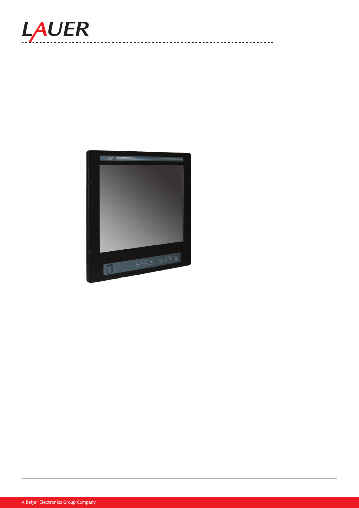
MT 223 NAV Monitor
© Elektronik-Systeme LAUER GmbH & Co. KG • 2007
Page 2

© Elektronik-Systeme LAUER GmbH & Co. KG • 2007
2
Table of content
1. Important notes 3
2. Included in delivery 4
3. Technical Introduction 5
4. Mounting 5
5. Installation 9
6. Functionality 10
6.1. Power On / Off Switch + Power-LED 11
6.2. Brightness 11
6.3. ECDIS-Mode 11
6.4. OSD Menu 11
6.4.1. Quick-OSD-Menu 11
6.4.2. OSD-Menu 12
6.4.3. Structure of the OSD menu (RGB) 13
6.4.4. Structure of the OSD menu (Digital/DVI) 17
6.4.5. Structure of the OSD menu (video) 17
6.4.6. Picture in picture possibilities 18
6.5. Front USB connection 19
6.6. Dimming 19
7. Interfaces and functions 20
7.1. Power Supply 21
7.2. Protected Ground 21
7.3. Composite 21
7.3.1. Composite connection 22
7.4. S-Video 22
7.4.1. S-Video connection: 22
7.5. VGA 23
7.5.1. VGA connection 23
7.5.2. VGA Cable 24
7.6. DVI 25
7.6.1. DVI connection 26
7.7. DIP switch 27
7.8. Serial Interfaces 28
7.9. Serial connection 29
7.10. LAN / Ethernet (RJ45) 30
7.10.1. Ethernet connection 31
7.10.2. Ethernet Cable 31
7.11. USB 32
7.12. USB connection 32
7.13. Analog IN 33
7.14. Digital IN 33
7.15. Digital OUT 34
7.16. Remote Power 34
8. Technical Data 35
9. Details 37
10. Contact 38
Page 3
© Elektronik-Systeme LAUER GmbH & Co. KG • 2007
3
1. Important notes
Please read the manual prior to using for the rst time and keep it in a safe place for future use.
Please check the Produkt and make sure, that it is not demaged.
Icons The following icons are used in the manual to mark certain paragraphs:
Danger!
Means that death or severe injury will occur when the relevant precautionary measures are
not taken
Caution!
Means that death or severe injury may occur when the relevant precautionary measures are
not taken.
Warning!
With warning triangle means that a light injury may occur when the relevant precautionary
measures are not taken.
Attention!
Without warning triangle means that material damage may occur when the relevant
precautionary measures are not taken.
Note!
Means that an undesirable effect or situation may occur if the respective advise is ignored.
The warning advise for the highest level is used if various danger levels occur. When a
warning advise with a warning triangle warns about personal damage then an additional
warning for material damage can be added.
Page 4
© Elektronik-Systeme LAUER GmbH & Co. KG • 2007
4
2. Included in delivery
Monitor Device MT 223
Power cable 3 m
DVI cable 3 m
VGA cable 3 m
Serial RS232 cable 3 m
USB cable 3 m
Ethernet cross patch cable 3 m
Driver manual CD
Mounting kit
Page 5
© Elektronik-Systeme LAUER GmbH & Co. KG • 2007
5
3. Technical Introduction
The MT232 NAV monitor has a multiplicity of interfaces and coupling possibilities.
The multiple possibilities of the dimming distinguish the monitor.
By several video sources e.g. a picture in picture (Split screen) function can be realized.
Also a cross-linking of the monitors as well as programming and control over serial or LAN is possible.
The USB front interface and a USB Hub 2.0 permits to attach directly at the monitor further devices.
Analog and digital in- and outputs for several control functions e.g. switch on/off power simultaneously from monitor
and PC or to dim complete the comprehensive functions
In the following chapters the functions, settings, menus, interfaces as well as the programming of the monitor are
described. Please read before going in operation the appropriate chapters “start-up” as well as the user and safety
references.
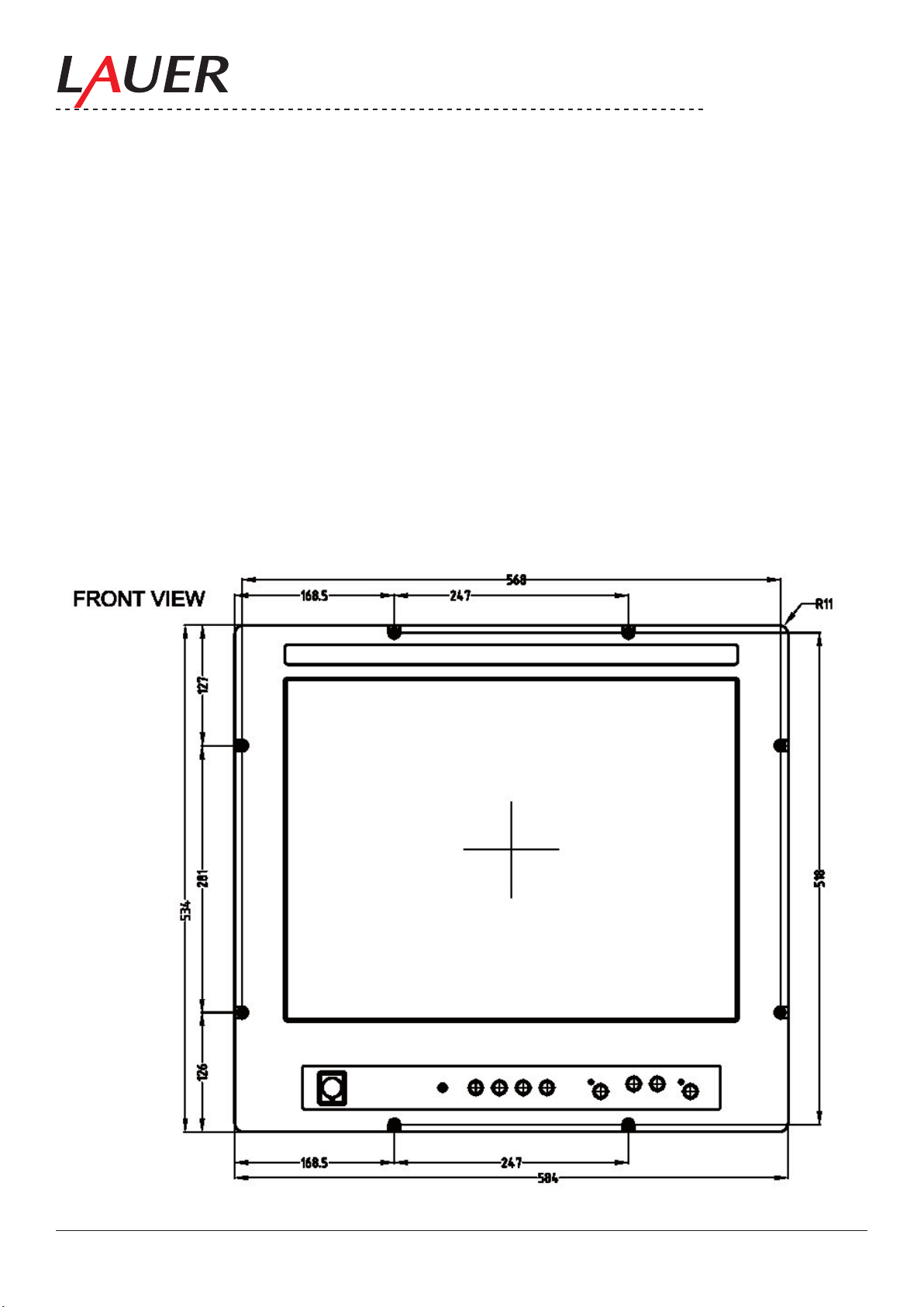
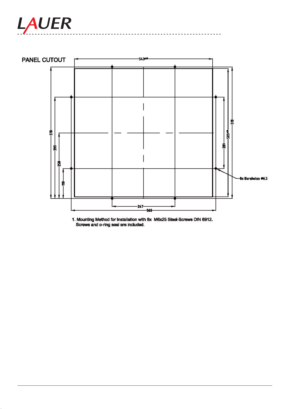
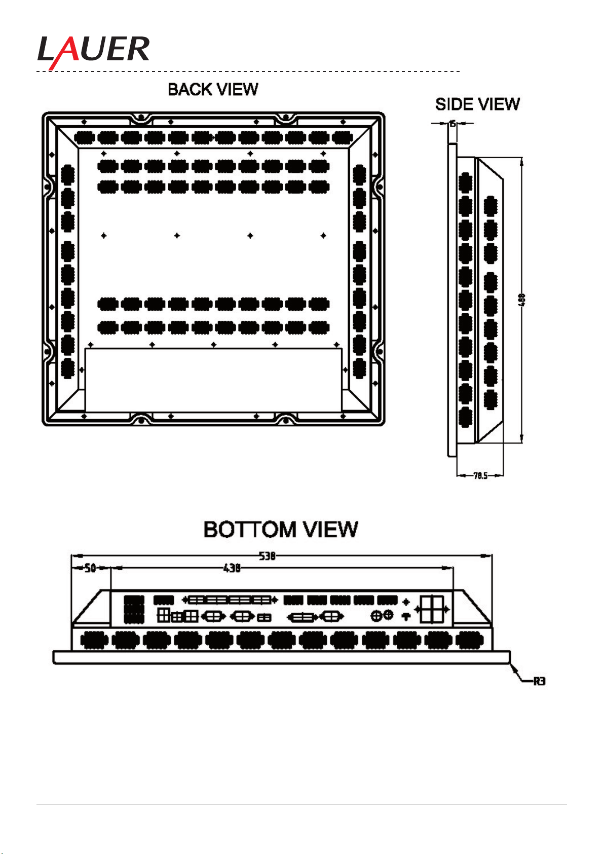
4. Mounting
Monitor Draft
Page 6
© Elektronik-Systeme LAUER GmbH & Co. KG • 2007
6
Page 7
© Elektronik-Systeme LAUER GmbH & Co. KG • 2007
7
Page 8
© Elektronik-Systeme LAUER GmbH & Co. KG • 2007
8
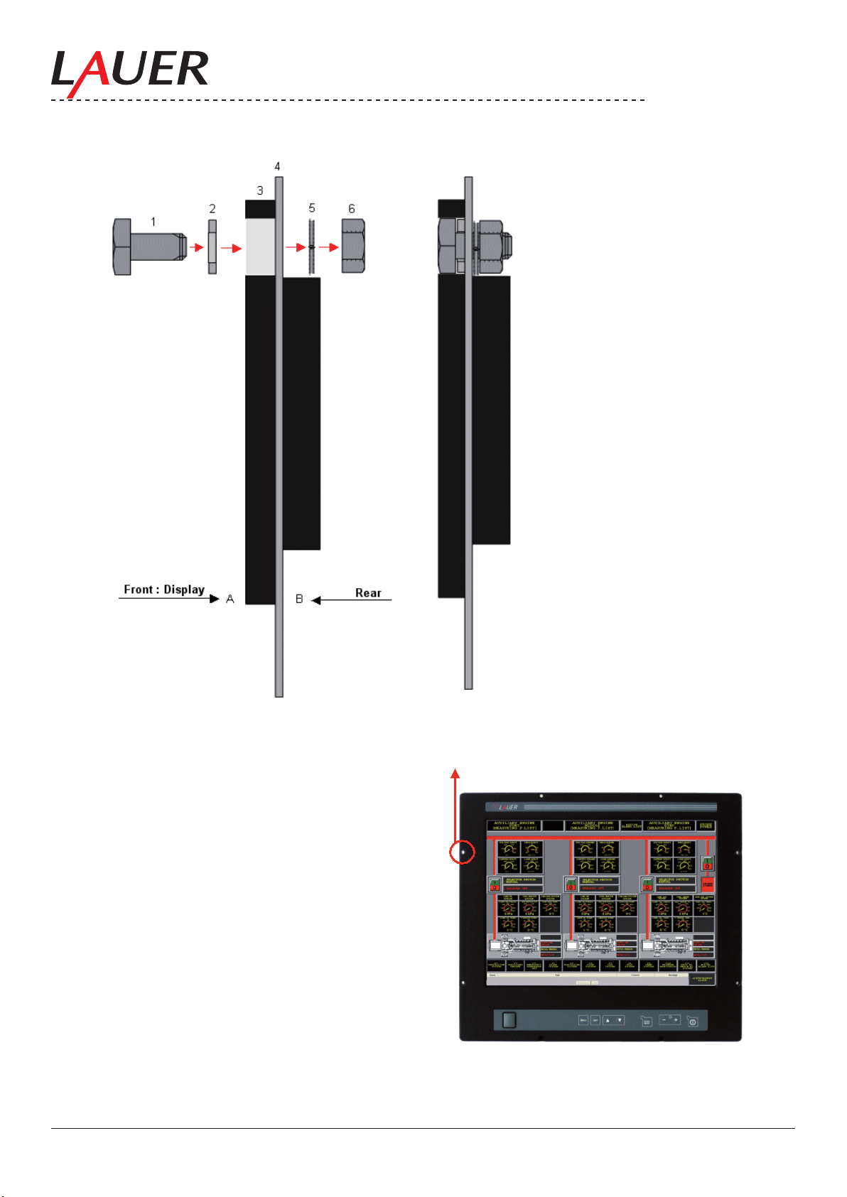
A: Front, Display
B: Rear
1: Screw M6x25
2: Rubber Seal M6
3: Monitor Front
4: Swichgear/ Monitor cabinet
5: Wave-disc
6: Nut/mother M6
Page 9
© Elektronik-Systeme LAUER GmbH & Co. KG • 2007
9
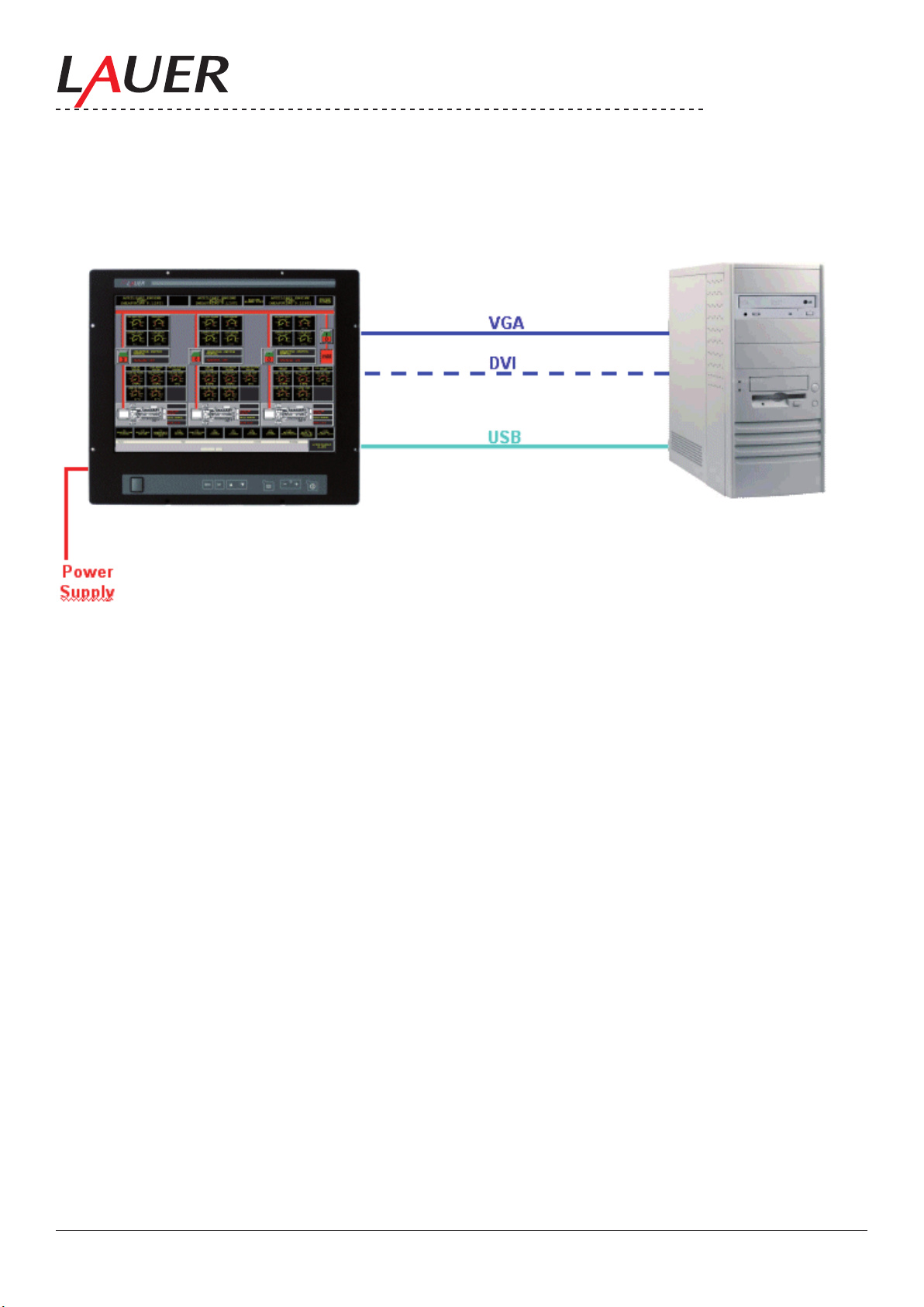
5. Installation
For standard (basis) installation is necessary apart from the current supply a video signal (mostly VGA or DVI), a USB
connection completes the standard installation.
Page 10
© Elektronik-Systeme LAUER GmbH & Co. KG • 2007
10
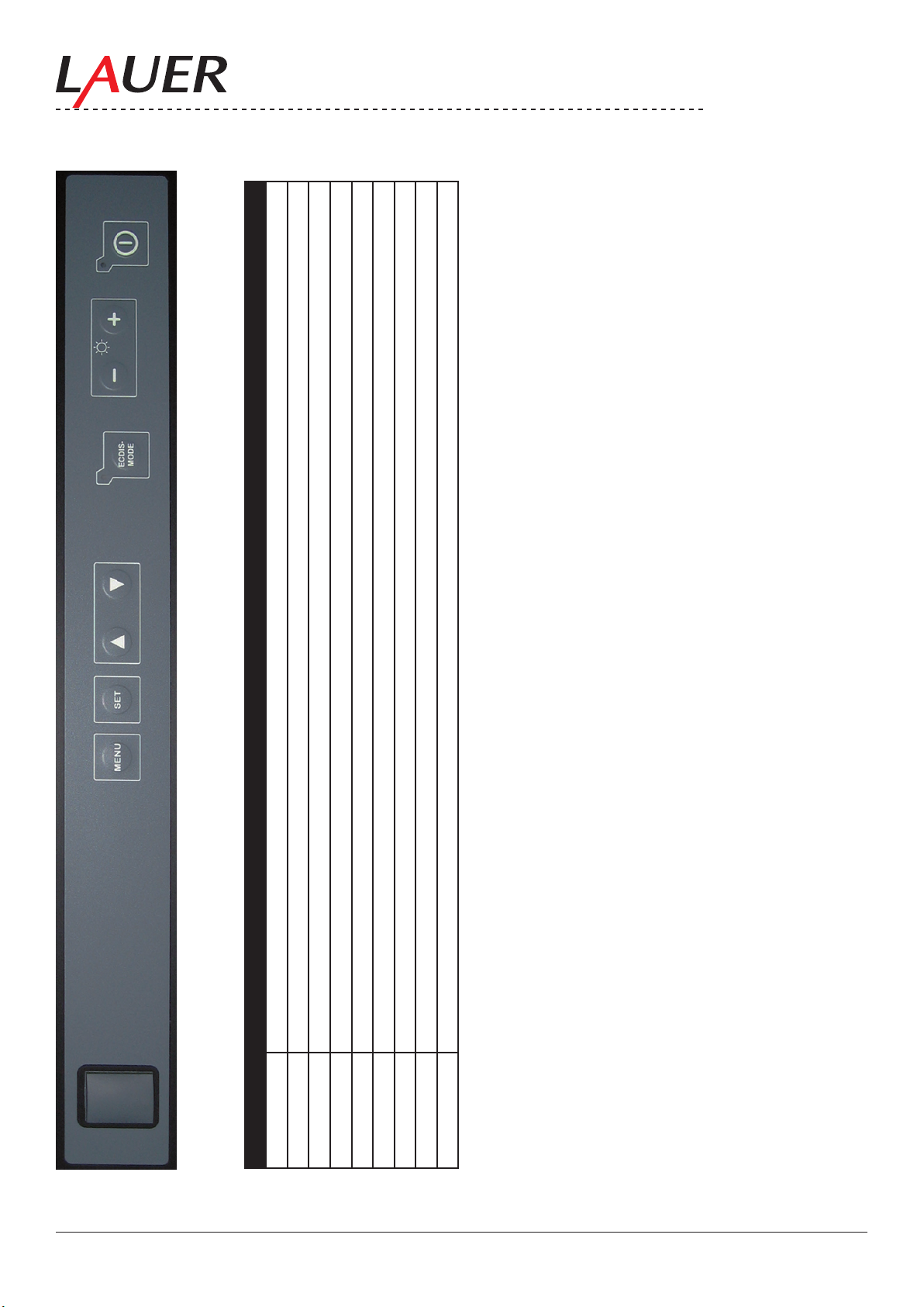
6. Functionality
Number Function
9 8 7 6 5 4 3 2 1
1 Power On/Off Switch + Power-LED
2 Contrast +
3 Contrast -
4 ECDIS Key / ECTIS LED
5 OSD Menu Cursor DOWN
6 OSD Menu Cursor UP
7 OSD Menu Set (Accept)
8 OSD Menu Start
9 Front USB Interface
Page 11
© Elektronik-Systeme LAUER GmbH & Co. KG • 2007
11
6.1. Power On / Off Switch + Power-LED
With the power On / Off switch (1) the monitor will be powered up and shut down, without disconnecting the power
supply . The bright LED indicates the switched on condition.
6.2. Brightness
With the keys (2) contrast+ and (3) contrast– the contrast is regulated.
(2) brightness + increments (increased) the contrast
(3) brightness – decrements (decreased) the contrast
6.3. ECDIS-Mode
With the ECDIS key (4) the brightness as well as the colors are set on a certain default value. See also chapter programming.
The bright LED indicates the switched on ECDIS mode.
ATTENTION:
If the ECDIS key is activated (LED on) automatically all other keys (contrast, OSD..)
are not active and cannot be operated.
Likewise no commands and/or programming over the serial and/or LAN (Ethernet) interface can be sent and accomplished.
6.4. OSD Menu
The OSD menu (on screen display menu) serves for adjustment and alignment of the monitor parameters e.g. contrast, brightness, zoom , video source etc..
The menu is divided into a „Quick OSD menu „ as the parameters brightness as well as contrast can be changed,
and a „OSD menu„ with all parameters are available.
6.4.1. Quick-OSD-Menu
The keys have the following Function(s):
Keys Function
<UP> Quick-OSD-Menu-Start:
Increase the values
Selection of the Input source
Automatic screen alignment accomplish
<DOWN> Adjusting parameter value degrade
MENÜ No function in the Quick OSD menu
SET Quick OSD menu start:
Adjustment of contrast, brightness
Adjustment of contrast, brightness
Adjustment of contrast, brightness
Page 12
© Elektronik-Systeme LAUER GmbH & Co. KG • 2007
12
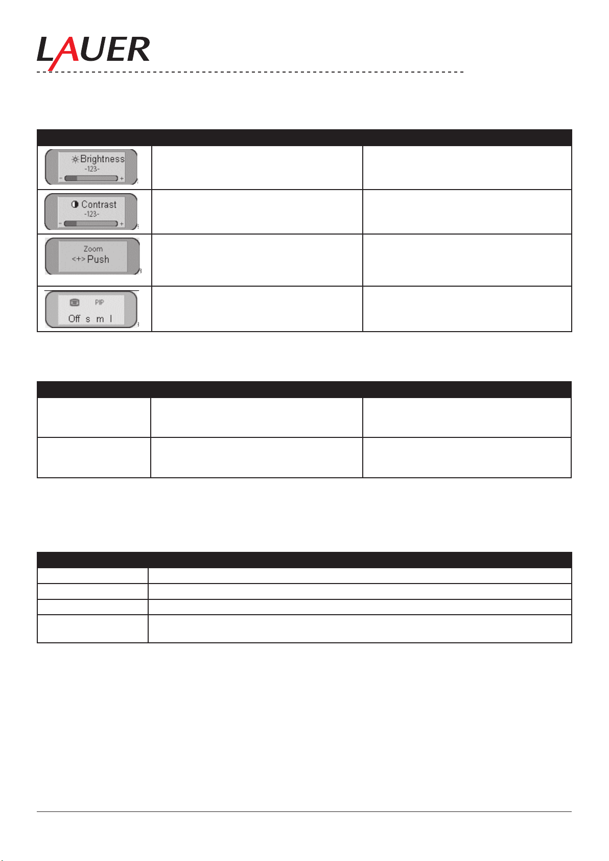
The following settings can be made over the Quick OSD menu:
Start with the key <SET>
Function Adjusting/setting Description
Range of adjustment: 0 to 100 over adjust-
Brightness adjustment:
ment keys (UP / DOWN)
Range of adjustment: 0 to 100 over adjust-
Contrast adjustment
ment keys (UP / DOWN)
Range of adjustment: 0 to 100 over adjustment keys (UP / DOWN)
Zoom adjustment: Enlargement of the
sceen contents. This Quickmenue has
additional submenus, which „zoom“ a shift
screen window is possible.
Range of adjustment small, means, largely Split Screen: select size of the faded in
video picture (PIP)
Start with the key <UP>
Function Adjusting/setting Description
Source RGB1, RGB2,
Digitally, FBAS, SVi-
Selection with key< SET >, selection with
key <UP>
Selection of the Input source
deo
screen alignment Alignment by renewed pressing of the
key<UP>
Accomplishes an automatic screen alignment. Alignment of frequency, phase and
picture position
6.4.2. OSD-Menu
The keys have the following Function(s):
Key Function
<UP> Adjusting parameter value increaseMenu selection to the right
<DOWN> Adjusting parameter value degradeMenu selection to the left
MENÜ OSD StartMain menu/submenu select
SET Entry of the main menu / Submenu from above step downward, select.Start with key
<MENÜ>:
Page 13

© Elektronik-Systeme LAUER GmbH & Co. KG • 2007
13
The OSD varies depending upon the straight represented signal source. The following
chapters describe once OSD functionality with represented RGB (VGA) signal and video (FBAS, s-video) signal.
6.4.3. Structure of the OSD menu (RGB)
Main
Function Adjusting/setting/range of adjustment Description
menue
Picture Brightness Range of adjustment: 0 to 100 over adjust-
Brightness adjustment
ment keys (UP / DOWN)
Contrast Range of adjustment: 0 to 100 over adjust-
Contrast adjustment
ment keys (UP / DOWN)
H Position Range of adjustment: 0 to 100 over adjust-
Picture in horizontal direction shift
ment keys (UP / DOWN)
V-Position Range of adjustment: 0 to 100 over adjust-
Picture in vertical direction shift
ment keys (UP / DOWN)
Phase Range of adjustment: 0 to 31 over adjust-
Phase of the input signal adjust
ment keys (UP / DOWN)
Frequency Range of adjustment:950 to 1050 (picture-
Frequency of the input signal adjust
dependently)over adjustment keys (UP /
DOWN)
Scaling Format lling; (correct aspect ratio); 1:1
representation
Fix, pre-dened scaling of the pictureIf „va-
riable“ is activated, the setting can be made
manually.
Scale dependent on resolution of the input signal Actively only if the function „scaling“ is ad-
justed „variable“. Free, nonlinear scaling of
the picture
Advanced Sharpness 1, 2, 3, 4, 5 Sharpness of the picture by choice one of
the ve sharpness degrees(Filter). 1=sharp
and 5= smoothly
Gamma Linear or CRT Gamma curve correctionColor values are
provided with a certain factor and passed on
to the display
Color temperature
5000 - 6500 – 9300 - VAR Desired color temperature and/or color
shadeThree rmly dened and a freely
adjustable color temperature are selectable.
If „VAR“ is activated for R,G, and B, in each
case an adjusting bar is shown. Range of
adjustment: 0 to 100 % (50% factor 1 corre-
sponds)
Page 14

© Elektronik-Systeme LAUER GmbH & Co. KG • 2007
14
PIP This option is only active if two signals ts.
Size Aus, klein, mittel, groß, user Size of the PIP window (PIP=Picture in
Picture).
Position 9 vordenierte Fensterpositionen Selection of the PIP window position
Source Auto, DVI, VGA 1, VGA 2, FBAS, S-VHS Selection of the input source of the repre-
sentation in the PIP window
Picture
- Brightness:
- Contrast Range of adjustment: 0 to 100 over adjust-
- Color Range of adjustment: 0 to 100 over adjust-
- Color
shade
Range of adjustment: 0 to 100 over adjustment keys (UP / DOWN)
ment keys (UP / DOWN)
ment keys (UP / DOWN)
Range of adjustment: 0 to 100 over adjust-
ment keys (UP / DOWN)
Brightness of the picture in the PIP window
adjust
Contrast of the picture in the PIP window
adjust
Color saturation of the picture in the PIP
window adjust
Color shade of the picture in the PIP window
adjust
PIP...
- H-Posi-
tion
- V-Posi-
tion
- Video
Range of adjustment: 0 to 100 over adjust-
PIP window position horizontal adjust
ment keys (UP / DOWN)
Range of adjustment: 0 to 100 over adjust-
PIP window position vertically adjust
ment keys (UP / DOWN)
Auto, NTSC, PAL, SECAM Selection video format
format
- Var. Size Range of adjustment: 0 to 100 over adjust-
PIP size variable adjust
ment keys (UP / DOWN)
- Sharp-
ness
Options 1 OSD OSD positions dened selection between
Range of adjustment: 0 to 100 over adjustment keys (UP / DOWN)
sharpness of the picture in the PIP window
adjust
Position OSD select
nine rmly
OSD H-
Position
OSD V-
Position
OSD Du-
ration
Range of adjustment: 0 to 100 over adjust-
OSD menu in horizontal direction shift
ment keys (UP / DOWN)
Range of adjustment: 0 to 100 over adjust-
OSD menu in vertical direction shift
ment keys (UP / DOWN)
5 ... 60 Seconds Adjust the time, after which the OSD menu
is faded out automatically, if no key is
pressed.The attitude takes place between 5
and 60 s in steps to 5 s
OSD
Back-
ground
Backlight Range of adjustment: 0 to 100 over adjust-
Opaque – Transparency Background colour of the OSD menu select.
You have the choice between a transparent
or covering background.
Brightness of the display backlight adjust.
ment keys (UP / DOWN)
Thus the total brightness of the picture can
be adapted to the room lighting.
Options 2 DPMS On – Off Display Power Management System
(DPMS) switch on or off. If the DPMS is ac-
tivated, the monitor switches off, as soon as
no more synchronisation signals t i.e. the
screen becomes darkly.
Signal
search
On – Off – Standard Video sources select, (not relevantly there
only a RGB input; default setting = On:
clear color Red – green – blue – black Selection of the background color of the
screen if no input signal ts
Page 15

© Elektronik-Systeme LAUER GmbH & Co. KG • 2007
15
Display Resolution of display Indicate to the physical resolution of the
attached display
Info Signal
source
On – Off Signal source info display switch on or offIn
the case of change one of the following set-
ting appears on the screen briey the signal
source info with the current signal source
information:- Signal source (e.g. RGB simi-
larly)- Mode (number of the table entry of the
internal Time table)- Resolution of the input
video source- H and V frequency
Options 3 Inter-
ference
suppression
On – Off Default setting OFF.ON: Activation of the
function for the suppression of interferences
in the synchronisation signals. It prevents
a renewed picture alignment during the
representation of a video signal when inter-
ferences are on the synchronisation signals.
RGB-Signal 1 lock
ON <UP> Default setting: OFF.ON: The straight
represented Videotiming is stored and
processed with a higher tolerance in H and
V-frequency. I.e. the attitudes of this timings
are always used, even if by interferences
variations in H and V-frequency arise. It pre-
vented when recognizing one interference
aficted video signal an incorrect timing re-
cognition e.g. in an incorrect picture centring
or picture resolution presents itself.
RGB-
Signal 1
OFF <UP> Default setting: OFF.(Video timing 1 again
releases)
unlock
RGB-Si-
gnal 2 lock
ON <UP> Default setting: OFF.ON: The straight
represented Videotiming is stored and
processed with a higher tolerance in H and
V-frequency. I.e. the attitudes of this timings
are always used, even if by interferences
variations in H and V-frequency arise. It pre-
vented when recognizing one interference
aficted video signal an incorrect timing re-
cognition e.g. in an incorrect picture centring
or picture resolution presents itself..
RGB-
Signal 2
OFF <UP> Default setting: OFF.(Videotiming 2 again
releases)
unlock
Utilities Language English – German Language for the operation of the OSD
menu select
Picture
ON – OFF Store (freeze) the picture content
freeze
Factory
setting
Mode
Video
<UP> push Reset all functions such as brightness, con-
trast… on factory settings.
normally, extended The function „extended“ activates a special
interlace algorithm. This attitude improves
the representation, particularly of static
video pictures.This attitude affects only on
video signals (PAL, SECAM,NTSC) which
are in full screen mode (no PIP.
Page 16

© Elektronik-Systeme LAUER GmbH & Co. KG • 2007
16
Installation RGB
Mode
At <+>,
- H- and VFrequency
- H/V-total,
H/V-start
- Options Var. RGB-Mode inactively, Mode1, Mode2,
- H-visible 100 to 2000 over adjustment keys (UP /
- V- visible 100 to 2000 over adjustment keys (UP /
- H- totally 100 to 2000 over adjustment keys (UP /
- H-Start 0 to 750 over adjustment keys (UP / DOWN) Number of pixels from H-Sync-start to the
- V-Start 0 to 500 over adjustment keys (UP / DOWN) Number of lines from V-Sync-start to the
- Install <UP> push Adjusted timing parameter are activated
Test sample
Infos Firmware,
Actual
working
time and
signal information
<UP> push Adjustment to video signals those Timing
data are not stored (if the indicated resoluti-
on at the display does not correspond to the
resolution of the source).With push of the
<+>-key, 9 adjustment possibilities appear
– Indicate H/V frequency of the current video
source
– Indicate the used timing parameters of the
current video source
Inactively: only using the internal timing
Mode3
tables Mode1: use the adjusted parameters
with complete, automatic alignment (usually
used)Mode2: use the adjusted parameters
with complete automatic alignment without
the automatic „position“ alignmentMode3:
use the adjusted parameters with complete-
ly automatic alignment without the automatic
„frequency“ alignment
Horizontal picture resolution adjust (most
DOWN)
important parameter)
Vertical picture resolution adjust (most imDOWN)
portant parameter)
Number of entire pixels in a line adjust (most
DOWN)
important parameter)
beginning of the picture adjust
beginning of the picture adjust
<UP> push Representation of a test picture
– Displaying of the current signal source
represented by rmware conditions, actual
working time and the Backlight and signal
information such as resolution, H and V-
frequency
Page 17

© Elektronik-Systeme LAUER GmbH & Co. KG • 2007
17
6.4.4. Structure of the OSD menu (Digital/DVI)
Main
Function Adjusting/setting/range of adjustment Description
menue
Picture Brightness Range of adjustment: 0 to 100 over adjust-
Brightness adjustment
ment keys (UP / DOWN)
Contrast Range of adjustment: 0 to 100 over adjust-
Contrast adjustment
ment keys (UP / DOWN)
Advanced Structure of menu the same as the structure of the OSD menu (RGB)
Option 1 Structure of menu the same as the structure of the OSD menu (RGB)
Option 2 Structure of menu the same as the structure of the OSD menu (RGB)
Option 3 Structure of menu the same as the structure of the OSD menu (RGB)
Utilities Structure of menu the same as the structure of the OSD menu (RGB)
Info Structure of menu the same as the structure of the OSD menu (RGB)
6.4.5. Structure of the OSD menu (video)
Main me-
Function Adjusting/setting/range of adjustment Description
nue
Screen Bright-
ness
Contrast Range of adjustment: 0 to 100 over adjust-
Range of adjustment: 0 to 100 over adjustment keys (UP / DOWN)
Brightness adjustment
Contrast adjustment
ment keys (UP / DOWN)
H Position Range of adjustment: 0 to 100 over adjust-
Picture in horizontal direction shift
ment keys (UP / DOWN)
V-Position Range of adjustment: 0 to 100 over adjust-
Picture in vertical direction shift
ment keys (UP / DOWN)
Phase Range of adjustment: 0 to 31 over adjust-
Phase of the input signal adjust
ment keys (UP / DOWN)
Frequen-cyRange of adjustment:950 to 1050 (picture-
Frequency of the input signal adjust
dependently)over adjustment keys (UP /
DOWN)
Scaling Format lling; (correct aspect ratio); 1:1
representation
Fix, pre-dened scaling of the pictureIf „va-
riable“ is activated, the setting can be made
manually.
Advanced Structure of menu the same as the structure of the OSD menu (RGB)
Video Video
Auto, NTSC, PAL, SECAM Selection of the video format
format
PIP Structure of menu the same as the structure of the OSD menu (RGB)
Scale Display
width
H- Linea-
rity
Range of adjustment: 0 to 100 over adjustment keys (UP / DOWN)
Range of adjustment: 0 to 100 over adjustment keys (UP / DOWN)
setting of the display width
Attitude of the horizontal linearity. Values
> 50 compress the picture in the picture
center. Only actively if the display width is
larger than the size of the monitor. Values <
50 stretch the picture in the picture center.
The display width is not changed.
H-Posi-
tion
Range of adjustment: 0 to 100 over adjustment keys (UP / DOWN)
Attitude of the horizontal picture position.
Actively only if the picture width is larger
than display width of the screen surface.
Page 18

© Elektronik-Systeme LAUER GmbH & Co. KG • 2007
18
Image
height
V- Linea-
rity
Range of adjustment: 0 to 100 over adjustment keys (UP / DOWN)
Range of adjustment: 0 to 100 over adjustment keys (UP / DOWN)
Einstellung der Bildhöhe
Attitude of the vertical linearity. Values > 50
compress the picture in the picture center.
Only actively if the display hight is larger
than the size of the monitor. Values < 50
stretch the picture in the picture center. The
display hight is not changed
V-Position Range of adjustment: 0 to 100 over adjust-
ment keys (UP / DOWN)
Attitude of the vertical picture position. Ac-
tively only if the picture hight is larger than
display screen surface.
Options 1 OSD OSD positions dened selection between
Position OSD select
nine rmly
OSD H-
Position
OSD
Duration
Range of adjustment: 0 to 100 over adjust-
OSD menu in horizontal direction shift
ment keys (UP / DOWN)
5 ... 60 Seconds Adjust the time, after which the OSD menu
is faded out automatically, if no key is
pressed.The attitude takes place between 5
and 60 s in steps to 5 s
OSD
Back-
ground
Opaque – Transparency Background colour of the OSD menu select.
You have the choice between a transparent
or covering background.
Options 2 Structure of menu the same as the structure of the OSD menu (RGB)
Utilities Language English – German Language for the
Picture
ON – OFF Store (freeze) the picture content
freeze
Factory
setting
Mode
Video
<UP> push Reset all functions such as brightness, con-
trast… on factory settings.
normally, extended The function „extended“ activates a special
interlace algorithm. This attitude improves
the representation, particularly of static
video pictures.This attitude affects only on
video signals (PAL, SECAM,NTSC) which
are in full screen mode (no PIP.
Info Structure of menu the same as the structure of the OSD menu (RGB)
6.4.6. Picture in picture possibilities
X: possible combinations
Page 19

© Elektronik-Systeme LAUER GmbH & Co. KG • 2007
19
6.5. Front USB connection
The front USB connection (9) is to connect directly devices e.g. keyboards, mouse, Memory stick and a fast and
simply operation and/or data handling. If the USB is not used, then this is locked with a rubber cap and thus IP65
protected.
See also chapter interfaces USB
By the interface (11) = USB (PC) the monitor is connected with the PC and thus a connection is realized from the PC
to the monitor front.
Moreover a USB HUB 2.0 is available on the back for further devices.
6.6. Dimming
For the dimming most different possibilities are available:
1. Dimming over the front keys
2. Dimming remote controlled over serial interface as well as over Ethernet
3. Dimming over potentiometers directly attached to the analog input
Characteristic:
The control - LED‘s of the keys are dim linear to the display.
Dim values
Dim value Display Function
0 0% Darkly + backlight off
255 100% Brightly
See also chapter “Interfaces and funktion” as well as chapter “programming”.
Page 20

© Elektronik-Systeme LAUER GmbH & Co. KG • 2007
20
7. Interfaces and functions
16 15 14 13
12 11 10 9 8 7 6 5 4 3 2 1
Nomber Function
1 Power Supply
2 Protected Ground
3 Composite Video second video source, for Picture in Picture function
4 S-Video Video second video source, for Picture in Picture function
5 VGA rst video source
6 DVI rst video source alternatively
7 DIP Switch Serial mode (RS232/485) + Monitor address
8 Serial COM B congure, control, status,
9 Serial COM A congure, control, status
10 LAN (Ethernet) congure, control, status
11 USB (PC) USB “connect through” function
12 USB-A / USB-B USB 2.0 Hub
13 Analog IN control
14 Digital IN control
15 Digital OUT control
16 Remote Power control
Page 21

© Elektronik-Systeme LAUER GmbH & Co. KG • 2007
21
7.1. Power Supply
The MT223 NAV is certied for the connection to protective grounded supplies EN60950.
1 Power supply 230 VAC
with fuse 1A T
7.2. Protected Ground
In order to ensure a safe derivative from electrical interferences,
the following points are to be considered:
• Connect device and device cabinet as short as possible with a central point of grounding.
• Pay attention to a low inductive connection between device and cabinet
• All data cables attached to the device are to be implemented with protected shield.
• The shields are to be grounded on both sites
• Between the connected systems a low impedance must exist. High balancing currents over the shield as consequence from potential differences are to be excluded.
• Execution of the grounding connection with min. 4 mm² cross section.
7.3. Composite
Composite video is the format of the analog TV signal, before it is modulated on a RF carrier (broadcast and/or television frequency). It is mostly in a standard format like NTSC, PAL or SECAM. It is compound from three source signals,
those with Y, U and V (together YUV) to be called. Y called the brightness of the picture and includes synchronization impulses. Thus this signal can be alone already used for the representation of a gray tone picture. U and V are
carriers of the color information. It rst from two to each other orthogonalen phases of the color carrier signal mixed
to a signal, which color value (chrominance) is designated. Therefore the signals Y and UV are mixed. Since Y is a
baseband signal and is mixed UV with a carrier, the developed signal equivalent is to frequency divided Multiplexing.
Function: Connection between second videos source and monitor to the transmission the video data
e.g. for PIP (Picture in Picture „Split screen“) function
Note:
The selection the videos source(s), synchronization, image position, window position as well as further settings are
accomplished in the OSD menu.
Page 22

© Elektronik-Systeme LAUER GmbH & Co. KG • 2007
22
7.3.1. Composite connection
FBAS Composite - Connector (male):
Pin Allocation Level Impedance Function
Inside Video signal
FBAS Y
Outside Ground for C 0 V Signalmasse
-0,3V-0,7 V 75 Ohm Combined video signal brightness, Color,
Sync
7.4. S-Video
S-Video (also known as Y/C) is a base band analog Video format. It offers a qualitatively better signal than Composite
video, nevertheless a worse than RGB - or Component video. The S-Video format divides the signal into two channels: Brightness (Luminance) and Color (Chroma).
Function: Connection between second videos source and monitor to the transmission the video data
e.g. for PIP (Picture in Picture „Split screen“) function
Note:
The selection the videos source(s), synchronization, image position, window position as well as further settings are
accomplished in the OSD menu.
7.4.1. S-Video connection:
Pin Function
01 Ground Luminance (Y)
02 Ground Chroma (C)
03 Intensity (Luminance) Y
04 Color (Chroma) C
Page 23

© Elektronik-Systeme LAUER GmbH & Co. KG • 2007
23
7.5. VGA
VGA is the abbreviation for video Graphics adapter or video Graphics array. It denes a computer graphic standard
(EISA 1987), concrete combinations of Picture resolution and color‘s number (bit depth) as well as repetition frequency and is practically identical to the MCGA (Multicolor Graphics adapter) of IBM. On the other hand it stands also
simply for the resolution 640 × 480 Pixels (aspect ratio 4:3) independently of other parameters.
Function: Connection between PC (rst video source) and monitor to the transmission the video data
Note:
The selection the videos source(s), synchronization, image position, window position as well as further settings are
accomplished in the OSD menu.
7.5.1. VGA connection
VGA- Connector VGA-Connector
(Monitor = 15-pol, female) (15-pol, male)
Pin Function
01 Red
02 Green
03 Blue
04 Monitor ID 2
05
06 GND
07 GND
08 GND
09 10 GND
11 Monitor ID 0
12 Monitor ID 1
13 H-Sync
14 V-Sync
15 –
Page 24

© Elektronik-Systeme LAUER GmbH & Co. KG • 2007
24
7.5.2. VGA Cable
Cable connection 15pol - > 15pol (male or female: Allocation pin number is alike!)
1 red 1
2 green 2
3 blue 3
13 HSYNC 13
14 VSYNC 14
6 red GND 6
7 green GND 7
8 blue GND 8
10 digital GND 10
15 pol DSUB (male) 15 pol DSUB (female)
Cable connection 15pol - > 9pol (male or female: Allocation pin number is alike!)
1 red 1
2 green 2
3 blue 3
13 HSYNC 13
14 VSYNC 14
6 red GND 6
7 green GND 7
8 blue GND 8
10 digital GND 10
15 pol DSUB (male) 9 pol DSUB (female)
Page 25

© Elektronik-Systeme LAUER GmbH & Co. KG • 2007
25
7.6. DVI
DVI (digital Visual interface) represents an all digital transmission of video data. Thereby become the quality (which
losses with the transformation of digital data into a analog video signal - and with digital image replication devices with
the transformation back in the digital signal) repaired.
Function: Connection between PC (rst video source) and monitor to the transmission the video data
Note:
The selection the videos source(s), synchronization, image position, window position as well as further settings are
accomplished in the OSD menu.
DVI: Technical data:
Transmission of video data over two TDMS links and in each case 3 channels
Maximum pixel clock per channel: 330 MHz
Data transmission rate up to 1,65 Gbit/s
Resolution when using DVI monitors: 2048 x of 1536 pixels
Single Link up to 1600 x 1200 pixel
Dual Link up to 2048 x 1536 pixel
Page 26

© Elektronik-Systeme LAUER GmbH & Co. KG • 2007
26
7.6.1. DVI connection
DVI-D (only digital) DVI-I (integrated, analog and digital)
Pin Function Pin Function
01 TDMS-Data 2- C1 Analog: Red
02 TDMS-Data 2+ C2 Analog: Green
03 Shield TDMS-Data 2,4 C3 Analog: Blue
04 TDMS-Data 4- C4 Analog: H-Sync
05 TDMS-Data 4+ C5 Analog: Ground
06 DDC clock
07 DDC Data
08 Analog: V-Sync
09 TDMS-Data 110 TDMS-Data 1+
11 Shield TDMS-Data
1, 3
12 TDMS-Data 3-
13 TDMS-Data 3+
14 +5 Volt
15 Ground for +5 Volt
16 Hotplug-Detect
17 TDMS-Data 0-
18 TDMS-Data 0+
19 Shield TDMS-Data 0,5
20 TDMS-Data 5-
21 TDMS-Data 5+
22 Shield TDMS-clock
23 TDMS-clock +
24 TDMS-clock –
Page 27

© Elektronik-Systeme LAUER GmbH & Co. KG • 2007
27
7.7. DIP switch
Over the DIP switches the serial interfaces mode as well as the monitor address can be adjusted.
With the distribution (default) are all DIP switches on OFF. This meant, the monitor is adjusted in address 0 in RS 232
mode.
4 DIP switches are for coding addresses, 16 addresses can be realized binary (0 – 15).
Therefore it is possible to connect 16 monitors over the RS485 interface.
Serial Mode:
DIP Switch 1 Mode
ON RS 485
OFF RS 232 (default)
Monitor Addresses:
Address DIP Switch 2 DIP Switch 3 DIP Switch 4 DIP Switch 5
0 OFF OFF OFF OFF
1 ON OFF OFF OFF
2 OFF ON OFF OFF
3 ON ON OFF OFF
4 OFF OFF ON OFF
5 ON OFF ON OFF
6 OFF ON ON OFF
7 ON ON ON OFF
8 OFF OFF OFF ON
9 ON OFF OFF ON
10 OFF ON OFF ON
11 ON ON OFF ON
12 OFF OFF ON ON
13 ON OFF ON ON
14 OFF ON ON ON
15 ON ON ON ON
Page 28

© Elektronik-Systeme LAUER GmbH & Co. KG • 2007
28
7.8. Serial Interfaces
RS-232: Interface serves for the data communication. Data will be transfered as ASCII code (American standard code
OF information inter-CHANGE). The RS232 represents a voltage-referred interface, and is thus only for short cable
lengths by approx. 10m - 15m suitably.
RS-485: bus interface operates as RS422 in the opposite clock mode; however only two lines are needed, which are
half duplex. The RS-485 makes connection possible of several transmitters and receivers with the help of a protocol
(up to 32 participants). The ISO standard 8482 plans a maximum cable length of 500 meters. With capacity and/or
absorption-poor, in pairs stranded (twisted pair) cable, can be increased the distance between two terminals: RS485
supports thus cable lengths of up to 1.2 km.
Function: Connection between PC and monitor to congure, control and read status. In the RS232 mode point to
point connection, in the RS485 mode interlacable to 16 monitors. Functions such as status read (rmware, version,
display ID…), control (brightness, backlight, potentiometer…) as well as congure (IP address, subfunctions of the
OSD menu…) are made available. (see chapter programming)
RS232 Mode
RS485 Mode
Note:
In the RS485 mode the two interfaces can be used as (In/Out) that means one cable in the 1st. Com port and one
cable in the 2nd. Com port.
In RS 232 mode only one of the two interfaces can be used (no matter whichone) don’t connect the unused port with
any cable.
The mode (RS232/RS485) as well as an addressing of the monitors are made over DIP switch, see also for this the
chapter “DIP- witches” and “programming”.
Page 29

© Elektronik-Systeme LAUER GmbH & Co. KG • 2007
29
DIP-Switch 1:
Schalter Mode
ON RS 485
OFF RS 232 (default)
7.9. Serial connection
(9) COM A SUB-D (male) (8) COM B SUB-D (female)
RS 232 Mode
PIN 9pol Designation Function In / Out
Pin 1 + 5 V Out
Pin 2 TxD,TX,TD Transmit Data Out
Pin 3 RxD,RX,RD Receive Data In
Pin 5 GND Ground
Pin 9 GND Ground
RS 485 Mode
PIN 9pol Designation Function In / Out
Pin 1 + 5 V Out
Pin 2 Data + Data In/Out
Pin 3 Data - Data In/Out
Pin 5 GND Ground
Pin 9 GND Ground
Page 30

© Elektronik-Systeme LAUER GmbH & Co. KG • 2007
30
7.10. LAN / Ethernet (RJ45)
Ethernet is one frame based computer cross-linking technology for local networks (LAN). It denes cable types and
signaling for the bit transmission layer (physical layer) and package formats and protocols for the medium access
supervision (Media Access Control, MAC) Link layer of the OSI Models. Ethernet is as far as possible in that IEEE
standard 802.3 standardizes. Ethernet can be the basis for network protocols , like e.g. TCP/IP .
Function: Connection between PC and monitor to congure, control and read status.
Functions such as status read (rmware, version, display ID…), control (brightness, backlight, potentiometer…) as
well as congure (IP address, subfunctions of the OSD menu…) are made available. (see chapter programming)
Direct connection
Connection over HUB/SWITCH
Page 31

© Elektronik-Systeme LAUER GmbH & Co. KG • 2007
31
7.10.1. Ethernet connection
Pin Function Description
01 Tx(+) Transmit data +
02 Tx(-) Transmit data 03 Rx(+) Reseive data +
04 -05 -06 Rx(-) Reseive data +
07 -08 --
7.10.2. Ethernet Cable
Crosspatch cable: Standard EIA/TIA-T456A
To connect two devices.
Patch cable: Standard EIA/TIA-T456B
To connect devices by HUB / SWITCH.
Page 32

© Elektronik-Systeme LAUER GmbH & Co. KG • 2007
32
7.11. USB
USB (Universal Serial Bus) is a Bus system for the connection of a Computer with external Devices for the exchange
of data. The USB is by the relatively high possible data rates and the automatic recognition of devices and their
characteristics for the connection of nearly all device types of Mouse and Keyboard up to Non removable disks and
Cameras suitably. The number of USB connections of a computer can also increased by USB HUB.
Function:
11 = USB (PC) “connect through” function of the USB interface of the PC to the monitor front
12 = USB-A / USB-B USB HUB
Note:
The distances of individual devices is without amplier for max. 5m appropriate.
7.12. USB connection
Pin Function Description
1 VBUS +5 VDC
2 D- Data -
3 D+ Data +
4 GND Ground
Page 33

© Elektronik-Systeme LAUER GmbH & Co. KG • 2007
33
7.13. Analog IN
Target application:
The analog input can be used for the dimming by voltage externally put on. The input dims several monitors together.
Alternatively also an external potentiometer (approx. 10kohm 100kohm –) can be attached as voltage dividers.
Function:
If the analog input is evaluated by the controller than is 10V for the full brightness and 0V completely darkly.
Plug:
3 pol Phoenix plug with “screw safety lock” RM3,81 for lines to 1,5mm²
Connection:
Pin Function Description
1 AVOUT Analog Output voltage
2 AIN Analog In
3 AGND Analog GND
Connection data:
AVOUT constantly 10V DC (max. 10mA) against AGND
AIN 0V – 10V against AGND
7.14. Digital IN
Target application:
The input are to be control the Buzzer or the digital outputs. They can be also used to activate features e.g. the analog
similar dimming. It is also conceivable that thereby for different brightness ranges (Day, Dusk, Night) a certain dim
value is activated. The exact function must be programmed into the rmware.
Function:
The contact „digitally in 1 - 3“ is evaluated by the Controller. They can be linked with the outputs „digitally Out“ or their
condition over the serial or LAN interface are sent.
Plug:
4 pol Phoenix plug with “screw safety lock” RM3,81 for lines to 1,5mm²
Connection:
Pin Function Description
1 In 1 Digital In 1
2 In 2 Digital In 2
3 In 3 Digital In 3
4 GND External GND
Connection data:
+24V DC against „external GND“. Galvanical separated.
Page 34

© Elektronik-Systeme LAUER GmbH & Co. KG • 2007
34
7.15. Digital OUT
Target application:
The outputs are used to give around e.g. externally acoustic or visual (alarm) signals.
Function:
The contacts „digitally Out 1“ and „digitally Out 2“ are activated by the controller. They can be linked with the inputs
„digitally in“ or in addition, over the serial or LAN interface to be set. „digitally Out 1“ is directly coupled with the Buzzer
on the front plate.
Plug:
4 pol Phoenix plug with “screw safety lock” RM3,81 for lines to 1,5mm²
Connection:
Pin Function Description
1 Digital Out 1 Normally open contact 1
2 Digital Out 1 Normally open contact 1
3 Digital Out 2 Normally open contact 2
4 Digital Out 2 Normally open contact 2
Connection data:
Relay contact 24V DC/1A or 230V AC/0,1A
7.16. Remote Power
Target application:
This switching contact is meant for remote control (off and on) to the picture signal giving PC‘s. Lauer Nautic PC‘s
have an appropriate input. So that the OFF/ON goes from monitor and PC synchronously, the PC should switch itself
on automatically when putting on supply voltage.
Function:
The contact is closed if the power key approx. 1s is pressed, and opens again if the power key is released.
Plug:
2 pol Phoenix plug with “screw safety lock” RM3,81 for lines to 1,5mm²
Connection:
Pin Function Description
1 Remote-Power Normally open contact
2 Remote-Power Normally open contact
Connection data:
Relay contact 24V DC/1A or 230V AC/0,1A
Page 35

© Elektronik-Systeme LAUER GmbH & Co. KG • 2007
35
8. Technical Data
Display:
Screen diagonal 23,1 inch (588 mm)
Active Area: 470 x 353 mm
Resolution: 1600 x 1200 pixel
Dot Pitch: 0.294 mm
Colours: 16.7 Mio.
Brightness: 0.5 – 220 cd/m²
Contrast Ratio: 500:1
Response Time: 10/20 ms (off/on)
LCD Technlogy: MVA
Viewing Angle: 160° / 160° (V/H)
Backlight Lifetime: 50000h
Video Signal Inputs:
VGA Level 0,7 Vpp @ 75 W
V-Frequency 50 – 100 Hz
H- Frequency 15 – 100 kHz
Pixel- Frequency max. 140 MHz
DVI TMDS (DVI1.0)
Pixel Frequency 25 – 165 MHz
S-Video PAL, NTSC, SECAM
Level 1 Vpp @ 75 W
V- Frequency 50 / 60 Hz
H- Frequency 15,625 / 15,734 kHz
Composite Video PAL, NTSC, SECAM
Level 1 Vpp @ 75 W
V- Frequency 50 / 60 Hz
H- Frequency 15,625 / 15,734 kHz
Remote Control Inputs:
LAN (Ethernet) Speed 10 /100 Mbit
Serial RS232 Baudrate 9600 8N1
Serial RS485 Baudrate 9600 8N1
Page 36

© Elektronik-Systeme LAUER GmbH & Co. KG • 2007
36
I/O-Ports:
Remote Power max Load 24 VDC / 1 A or 230 VAC / 0,1 A
Digital Out max. Load 24 VDC / 1 A or 230 VAC / 0,1 A
Digital In Input Voltage +24 VDC +/-15 % (galvanically isolated)
Analog In Output Voltage 10 VDC (max. 10 mA)
Input Voltage 0 – 10 V
Other Ports:
USB2.0 Speed 480 Mbps
Output Current 0,5 A
Power Supply:
Voltage 115 – 230 V +/-15 %
Current max. 1 A
Power max. 100 W
Environment:
Operating Temperature: - 15° to +55° C
Storage Temperature: - 20° to +60° C
Humidity up to 95 % (non-condensing)
Protection IP65 Front
IP20 Back
Mechanical:
Dimensions 584 x 534 x 100 mm
Weight 18 kg
Page 37

© Elektronik-Systeme LAUER GmbH & Co. KG • 2007
37
9. Details
Qualied personnel The described appliance may only be installed and operated in accordance with this
documentation. Only qualied personnel may put it into operation and operate this appliance.
Qualied personnel are persons, who in accordance with the safety regulations contained in
this documentation, are authorised to put into operation, earth and stamp appliances,
systems and circuits.
Intended use The appliance can only be used for the designated purposes as described in the catalogue
and the technical write up and only in conjunction with external devises i.e. components
recommended and authorised by Elektronik-Systeme LAUER GmbH & Co. KG. The efcient
and safe operation of the appliance presupposes appropriate transport, storage, assembly
and installation as well as accurate handling and maintenance.
Operating instructions, manuals and software are copyrighted. All rights are reserved. Copying, duplicating, translating, transcribing en bloc or partially is prohibited. An exception is the making of a software back up copy for private
use.
• We reserve the right to make amendments to the manual without prior notice.
• We can not guarantee the accuracy and correctness of the programmes and data stored on
the CD-ROM.
• Helpful suggestions, improvements as well as references to errors are welcome at any time.
• The stipulations are also valid for any special annexes to this manual.
Microsoft, Windows 2000, Windows XP and the Windows Logo are either registered trademarks or trademarks of the
Microsoft Corporation in the USA and/or other countries.
The above terms in this documentation can be brands, whose use by third parties can breach the rights of the proprietor.
Page 38

10. Contact
Elektronik Systeme LAUER GmbH & Co. KG
P.O Box 1465
D-72604 Nürtingen
Support contact
Telephone: +49 (0) 7022 / 9660 -209
eMail: Support@systeme-lauer.de
for support inquiries always have the serial number of your appliance at hand!
Up to date driver units, software, driver units, manuals ...and innovations can be found in our download-forum:
http://forum.systeme-lauer.de/
Sales contact
Telephone: +49 (0) 7022 / 9660 -0
eMail: Sales@systeme-lauer.de
Operating instructions: MT 223 NAV Monitor
issue: 29. Juni 2007
editor: Mutter
© Elektronik-Systeme LAUER GmbH & Co. KG • 2007
38
 Loading...