

Page 1

M70
Installation Manual
MAEN843A 2007-12
English
Page 2

Foreword
M70 Installation Manual
Foreword
The handheld operator panel M70 is a portable operating and display device with
rugged design and Windows-CE compatible electronics.
Using a high-performance Intel PXA270 processor and providing a serial interface
or Ethernet, the M70 is ideal for a great variety of applications.
The touch screen and graphic elements in color offer intuitive operation.
High safety is ensured by the emergency stop switch and the enabling switch.
© Beijer Electronics AB, MAEN843A, 2007-12
The information in this document is subject to change without notice and is provided as available at the time
of printing. Beijer Electronics AB reserves the right to change any information without updating this
publication. Beijer Electronics AB assumes no responsibility for any errors that may appear in this document.
Read the entire installation manual prior to installing and using this equipment.
Only qualified personnel may install, operate or repair this equipment. Beijer Electronics AB is not
responsible for modified, altered or renovated equipment.
Because the equipment has a wide range of applications, users must acquire the appropriate knowledge to use
the equipment properly in their specific applications.
Persons responsible for the application and the equipment must themselves ensure that each application is in
compliance with all relevant requirements, standards and legislation in respect to configuration and safety.
Only parts and accessories manufactured according to specifications set by Beijer Electronics AB may be used.
BEIJER ELECTRONICS AB SHALL NOT BE LIABLE TO ANYONE FOR ANY DIRECT, INDIRECT,
SPECIAL, INCIDENTAL OR CONSEQUENTIAL DAMAGES RESULTING FROM THE INSTALLATION, USE OR REPAIR OF THIS EQUIPMENT, WHETHER ARISING IN TORT, CONTRACT, OR
OTHERWISE. BUYER'S SOLE REMEDY SHALL BE THE REPAIR, REPLACEMENT, OR REFUND
OF PURCHASE PRICE, AND THE CHOICE OF THE APPLICABLE REMEDY SHALL BE AT THE
SOLE DISCRETION OF BEIJER ELECTRONICS AB.
Beijer Electronics, MAEN843A
Page 3

Contents
Contents
1 Safety Precautions................................................................................... 5
1.1 General ........................................................................................5
1.2 During Use..................................................................................6
1.3 Service and Maintenance..............................................................7
1.4 Dismantling and Scrapping..........................................................7
2 Hazard and Risk Analysis........................................................................ 8
3 Description of Parts................................................................................9
4 Connection........................................................................................... 10
4.1 Cable Entrance Area ..................................................................10
4.2 RS232C Connection..................................................................12
4.3 Ethernet Connection .................................................................13
5 Emergency Stop....................................................................................15
6 Enabling Switch.................................................................................... 16
6.1 Examples of Connecting the Enabling Switch to Hardware........ 17
7 Touch Screen ........................................................................................19
7.1 Screen Saver............................................................................... 19
8 Key Switch............................................................................................20
8.1 Touch Screen Calibration...........................................................20
8.2 Service Menu .............................................................................20
9 USB Memory Sticks ............................................................................. 22
9.1 Connecting a USB Memory Stick..............................................22
9.2 Recommended USB Memory Sticks ..........................................22
10 Configuration Tool for the Operator Panels ......................................... 23
11 Start-up Procedure................................................................................ 24
11.1 Date and Time Handling in the M70 ........................................24
Beijer Electronics, MAEN843A
Page 4

Contents
12 Technical Data...................................................................................... 25
13 Outline Drawings .................................................................................29
14 Connection Box....................................................................................31
14.1 Technical Data of Connection Box.............................................32
14.2 Connecting M70 to Connection Box.........................................33
14.3 Interior View of Connection Box ...............................................34
14.4 Pin Description of X1 Terminal Block........................................35
14.5 Technical Data of the Connection Terminals..............................35
15 Cables and Accessories ..........................................................................37
15.1 Connection Cable ......................................................................37
15.2 Wall Mounting Kit.....................................................................37
Beijer Electronics, MAEN843A
Page 5

Safety Precautions
1 Safety Precautions
Both the installer and the owner and/or operator of the handheld operator panel
must read and understand this installation manual.
1.1 General
– Only qualified personnel may install or operate the handheld operator panel.
– The handheld operator panel must be installed according to the installation
instructions.
– The handheld operator panel is designed for installation where the following
conditions are fulfilled:
• no high explosive risks
• no strong magnetic fields
•no direct sunlight
• no large, sudden temperature changes
– Never allow fluids, metal filings or wiring debris to enter any openings in the
handheld operator panel. This may cause fire or electrical shock.
– The handheld operator panel fulfills the requirements of article 4 of EMC
directive 89/336/EEC.
– The handheld operator panel meets the protective class III in accordance with
EN61131-2 and EN50178.
– When connecting the handheld operator panel, make sure that all voltages
connected to the handheld operator panel are safety extra low voltages and
isolated from the low voltage supply system by a safety transformer or a similar facility. All supply circuits connected to the handheld operator panel must
be protected with a fuse of a maximum of 3.15 A.
– Storing the handheld operator panel where the temperature is lower/higher
than recommended in this manual can cause the LCD display liquid to
congeal/become isotopic.
– The LCD display liquid contains a powerful irritant. In case of skin contact,
wash immediately with plenty of water. In case of eye contact, hold the eye
open, flush with plenty of water and get medical attention.
– The supplier is not responsible for modified, altered or reconstructed
equipment.
Beijer Electronics, MAEN843A 5
Page 6

Safety Precautions
– Use only parts and accessories manufactured according to specifications of the
supplier.
– Peripheral equipment must be appropriate for the application and location.
– The figures in this manual serves an illustrative purpose. Because of the many
variables associated with any particular installation, the supplier cannot
assume responsibility for actual use based on the figures.
– The supplier neither guarantees that the handheld operator panel is suitable
for your particular application, nor assumes responsibility for your product
design, installation or operation.
1.2 During Use
– Keep the handheld operator panel clean.
– Do not use too much force or sharp objects when touching the keys, display
etc.
– Do not lay the handheld operator panel down with the operating side facing
down, since this may cause unintentional activation of the handheld operator
panel, or damage the operating elements.
Emergency Stop Button
– Not fully functional emergency stop devices may have fatal consequences!
Emergency stop switches which are red-yellow marked must be effective
under all circumstances in all operating modes of a machine or plant.
– Store handheld panels with not operational red-yellow emergency stop
switches on a place where the operator cannot see it, so that he cannot mistake
the device.
– Resetting an activated emergency stop facility must not result in uncontrolled
start-up of machines or installations.
– The emergency stop button does not replace other safety facilities.
– The emergency stop button on the handheld operator panel does not replace
the emergency stop buttons to be mounted directly on the machine.
– Some mechanical errors in emergency stop switches can be recognized at
operation only.
– Test the function of the emergency stop switch if the handheld operator panel
has been exposed to mechanical shock (e.g. fallen on the ground).
6 Beijer Electronics, MAEN843A
Page 7

Safety Precautions
Enabling Switch
– The enabling switch is only suitable as safety function if the operator activat-
ing the enabling switch recognizes the dangerous situation in time so that he
can immediately take the necessary measures to avoid such situations.
– As additional measure reduced speed of the movement can be necessary. The
allowed speed must be determined by means of a risk assessment.
– The enabling switch is only used to enable commands for performing danger-
ous movements. The commands themselves must be activated by a separate
operating element (key on handheld operator panel).
– Only the person who operates the enabling switch is allowed to work in the
dangerous area.
Note:
The enabling switch is hardware dependent, and are separa ted from the soft ware
running in the operator panel. The panel will functio n no rmal ly, regardless of t he
status of the enabling switch. See section Enabling Switch for information.
1.3 Service and Maintenance
– Only qualified personnel should carry out repairs.
– The agreed warranty applies.
– Before carrying out any cleaning or maintenance operations, disconnect the
equipment from the electrical supply.
– Clean the display and surrounding front cover with a soft cloth and mild
detergent.
1.4 Dismantling and Scrapping
– The handheld operator panel or parts thereof shall be recycled according to
local regulations.
– The following components contain substances that might be hazardous to
health and the environment: electrolytic capacitor and display.
Beijer Electronics, MAEN843A 7
Page 8

Hazard and Risk Analysis
2 Hazard and Risk Analysis
For manual control of machines in special operating modes, where safety depends on the timely reaction of the operating staff, it is absolutely essential that
the operator can overlook the operating area.
The handheld operator panel has the advantage that the operator can get very
close to the control panel. At the same time, the danger of misuse increases with
mobility since, in remote locations where it is not possible to observe the operating area, machine movements can also be set in motion with the handheld operator panel, knowingly or unknowingly. The machine operator has to find the
right compromise between necessary flexibility and a reasonable limitation of
the working range when selecting the cable length for the handheld operator
panel.
If the machine or equipment is operated with the handheld operator panel, care
must be taken at this time to ensure that operation can only be controlled by the
handheld panel and cannot be operated from any other point on the equipment.
The hazard zone may only be entered by the person who is operating the handheld panel. If it should be necessary for more than one person to work in the
hazard zone at the same time, each person present requires an enabling device
and machinery movement may only be allowed after all the enabling devices
have been activated.
For the right projecting of the handheld operator panel, a hazard and risk analysis must be carried out. In addition to chapter 1 Safety Precautions, the following safety aspects is to be considered:
– Which is the correct cable length for limitation of work space?
– Is an emergency stop button necessary and permissible?
– Is the safety category for the application sufficient?
The handheld operator panel may be operated in faultless condition only and
the operating instructions must be observed.
Moving around with a cable connected device also requires consideration. To
avoid damage to the cable or the cable sheath, the cable must not be squeezed or
laid over sharp edges.
See also chapters 5 Emergency Stop and 6 Enabling Switch.
8 Beijer Electronics, MAEN843A
Page 9
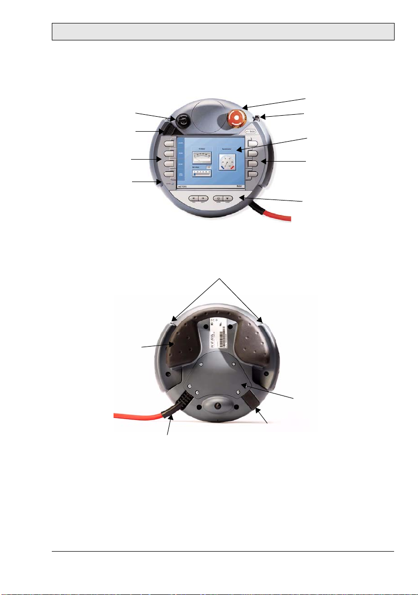
3 Description of Parts
Key switch
USB memory stick
protection cover
4 function keys
Power LED
Two 3-position enabling
switches, twin circuit
Description of Parts
Emergency stop switch
Touch stylus
(integrated in housing)
Color display with touch
screen
4 function keys
4 function keys
Multigrip handle
Cable entrance area
Blind plug for cable outlet not used
Strain relief and bend protection
for connection cable
(to meet protection degree IP 65)
Beijer Electronics, MAEN843A 9
Page 10
Connection
4 Connection
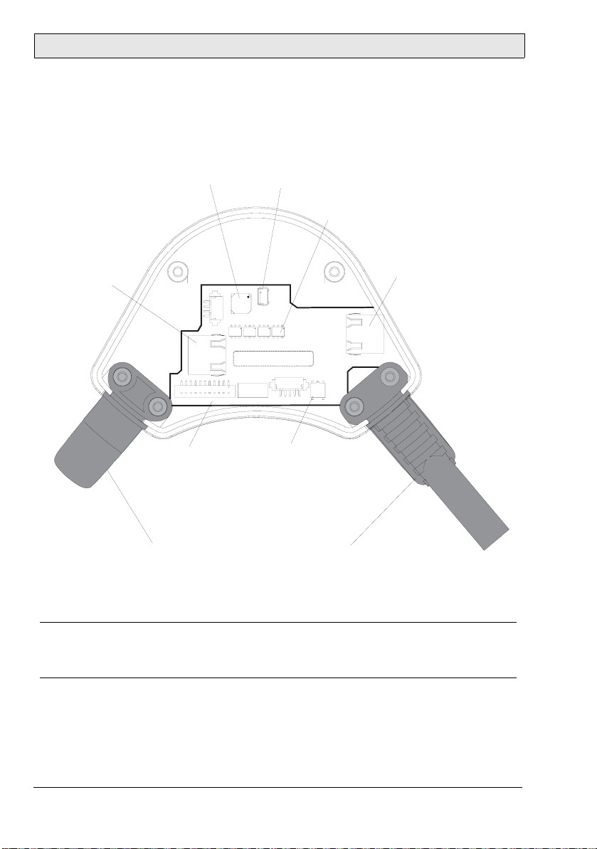
4.1 Cable Entrance Area
RS-232-C (S11)
for data exchange
Summer
S11
Main Plug (S22)
Powersupply,
Enabling device,
E-Stop
Sealing Plug
Must be used
to ensure
impermeability!
1
S20
B4H1B3
Serien-Art.-Nr. E tikett
USB-Client (S12)
S12
B5 B2
CAS-220T B1
CAS-220TB1
S28
S10
Reset button
Restarts device.
All unsa ved data will be lost
Strain Relief of Cable
for connecting cable
(on left or right side).
ATTENTION:
Use blind plug on
cable outlet not used.
Dip switches
Configuration RS-422-A or RS-232-C
(default RS-422-A but only RS-232-C
is supported)
ETHERNET (S4)
for data exchange
S4
B1
Note:
When the cable entrance area is open, the M70 is sensitive to electrostatic discharge.
10 Beijer Electronics, MAEN843A
Page 11
Connection
Cable Routing in Cable Entrance Area
Cable routing makes it possible to adapt the M70 to suit either a right- or lefthanded user better.
After opening the cable entrance area, the connecting lines can be routed as described in the following section. Before opening the M70 please pay attention
to the safety instructions below.
Instructions for opening the cable entrance area:
– Place the M70 with the display facing down onto a plane and clean table
(preferable on ESD pad) and take care not to damage the M70 and its operating elements.
– For opening and closing the cable entrance area a Phillips size 2 screwdriver
is used.
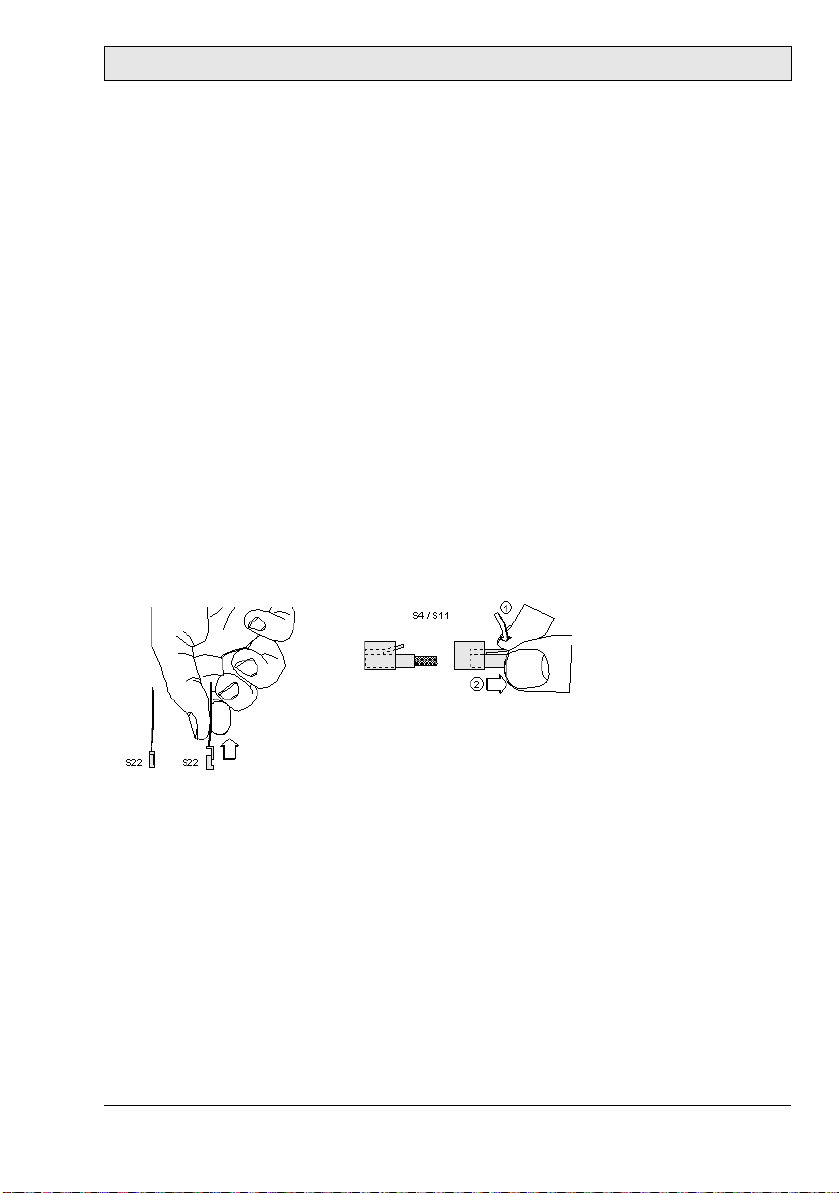
Instructions for modifications in the cable entrance area:
– Unplug the main connector (S22) by pulling on its wires with your fingers.
Do not use any sharp objects.
– For unplugging the RJ-45 jack (S11or S4), actuate the locking lever:
Make sure that the connectors S22 and S4 / S11 correctly snap in when you plug
them in. Otherwise the emergency stop functionality (S22) or the correct shielding (S4 / S11) might not be given anymore.
Instructions for closing the cable entrance area:
– Make sure that the sealing is clean, not damaged and correctly positioned in
the cable entrance area.
– Make sure that no cables are squeezed in.
– Make sure that the cover of the cable entrance area is attached again with all
6 screws (torque: 0.4 - 0.5 Nm).
Otherwise the protection degree cannot be guaranteed.
Beijer Electronics, MAEN843A 11
Page 12
Connection
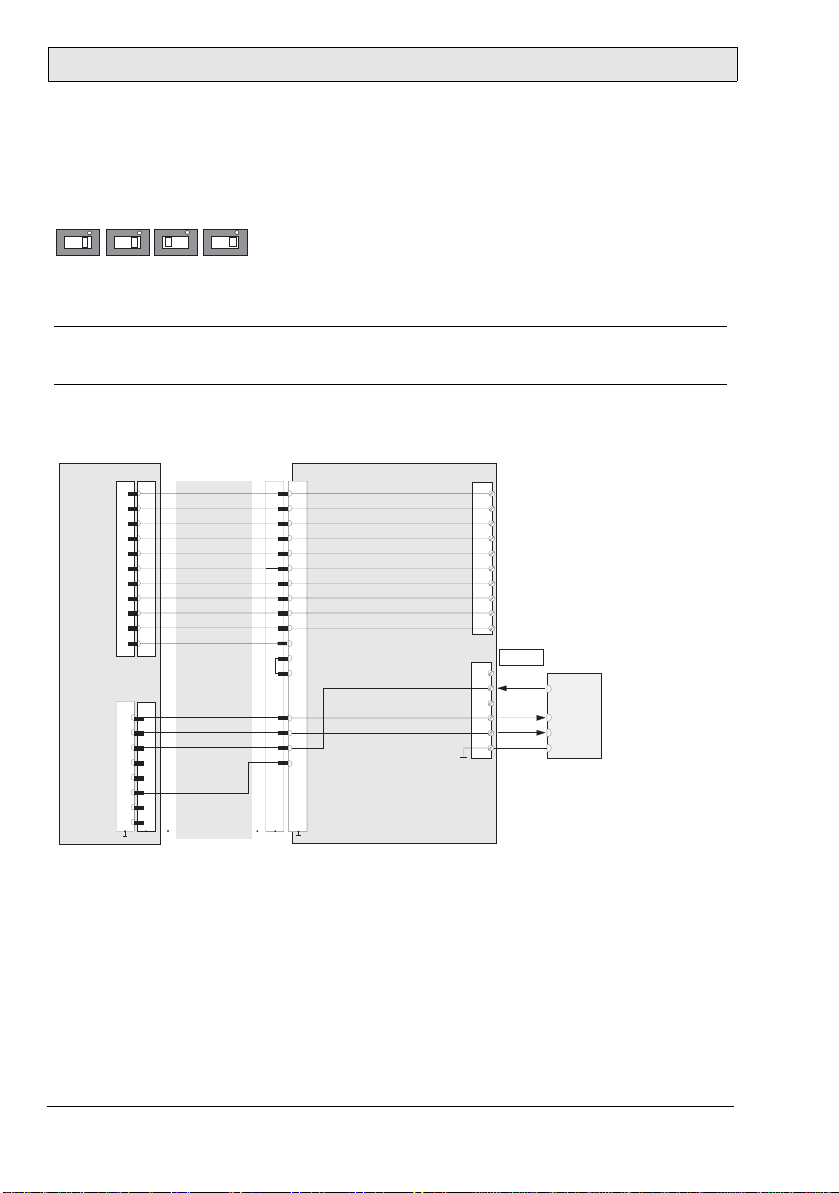
4.2 RS232C Connection
The serial interface is used as an RS232C interface. The dip switches has to be
set according to below for RS232C communication:
B5
B4 B2B3
The COM-SIO connector S11 in the cable entrance area of the M70 is used.
Note:
The RS232C connection cannot be used simultaneously with an Ethernet connection.
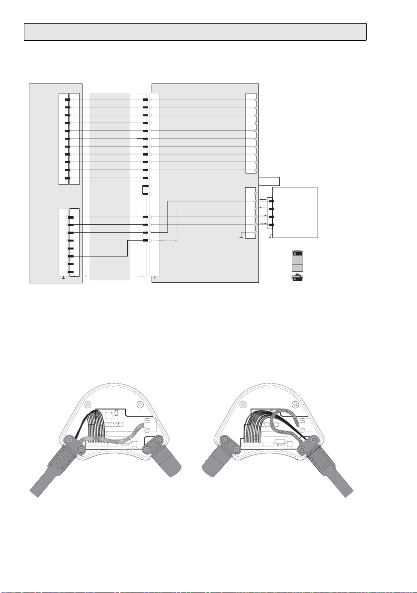
4.2.1 RS232C Wiring Diagram
TxD
RTS
RxD
M70
S22 K3
S6
6
7
8
9
10
11
1
2
3
4
5
K2
1
2
3
6
Connection cable
CABTTxxx
pink
black
brown-green
white-green
grey-pink
red-blue
brown
yellow
green
grey
violet
blue
white
orange
red
K1
K1
1
2
3
4
5
6
7
8
12
17
11
9
10
S1
1
13
14
15
16
Connection box CB211
E-STOP_ES1+
E-STOP_ES2+
ENABLE_ED1+
ENABLE_ED1-
ENABLE_ED2+
ENABLE_ED2-
+24 V DC
GND
E-STOP_ES1-
E-STOP_ES2-
RxD
TxD
RTS
SHIELD
X1
1
24 VDC
GND_IN
2
3
Emergency stop, circuit 1
Emergency stop, circuit 1
4
5
Emergency stop, circuit 2
6
Emergency stop, circuit 2
7
Enabling switch, circuit 1, pos.
8
Enabling switch, circuit 1, neg.
9
Enabling switch, circuit 2, pos.
10
Enabling switch, circuit 2, neg.
RS-232-C
X3
1
2
3
4
5
6
External device
TxD
RxD
CTS
GND
12 Beijer Electronics, MAEN843A
Page 13

Connection
4.2.2 RS232C Cable Outlet
The drawing below illustrates the cable outlet when the RS232C interface is
used.
S12
1
S20
B4H1B3B5
B2
CAS-220TB1B1CAS-220TB1
Serien-Art.-Nr. Etikett
S11
S10
right left
S4
S28
S12
1
S20
B5
B4H1B3
B2
CAS-220TB1
CAS-220TB1
Serien-Art.-Nr. Etikett
S11
S10
S4
S28
B1
4.3 Ethernet Connection
The M70 is equipped with an Ethernet interface based on the 10 Base T specification and suitable for half-duplex mode.
The Ethernet connector S4 (marked ETHERNET) in the cable entrance area of
the M70 is used.
The following interface parameters are defined and cannot be changed:
–10 Mbit/s
– TCP/IP protocol
If the M70 and the control do not communicate via a point-to-point connection, it may happen that the keypad data, for example, are transmitted with a
delay. To avoid this, it is advisable to establish the connection via an Ethernet
switch which enables a point-to-point connection.
The positions of the dip switches in the cable entrance area are not relevant for
this interface.
Note:
The Ethernet connection cannot be used simultaneously with an RS23 2C connection.
Beijer Electronics, MAEN843A 13
Page 14
Connection
4.3.1 Ethernet Wiring Diagram
M70 Connection Box CB211
S22 K3
S4
TD+
TD-
RD+
RD-
6
7
8
9
10
11
1
2
3
4
5
K2
1
2
3
6
Connection cable
CABTTxxx
pink
black
brown-green
white-green
grey-pink
red-blue
brown
yellow
green
grey
violet
blue
white
orange
red
K1
K1
1
1
2
2
3
3
4
4
5
5
6
6
7
7
8
8
12
12
17
17
not used
11
11
9
not used
9
not used
10
10
E-STOP_ES1+
E-STOP_ES1-
E-STOP_ES2+
E-STOP_ES2-
ENABLE_ED1+
ENABLE_ED1-
ENABLE_ED2+
ENABLE_ED2-
S1
1
13
13
14
14
15
15
16
16
+24 V DC
GND
RD+
RDTD+
TD-
SHIELD)
X1
1
24 VDC
GND_IN
2
3
Emergency stop, circuit 1
Emergency stop, circuit 1
4
5
Emergency stop, circuit 2
6
Emergency stop, circuit 2
7
Enabling switch, circuit 1, pos.
8
Enabling switch, circuit 1, neg.
9
Enabling switch, circuit 2, pos.
10
Enabling switch, circuit 2, neg.
Ethernet
RJ45
External device
Hub / PC
3 (RD+) /
6 (RD-) /
1 (TD+) /
2 (TD-) /
X3
1
2
3
4
5
6
Pin numbering RJ45:
Top:
Front:
e.g.:
18
18
1 (TD+)
2 (TD-)
3 (RD+)
6 (RD-)
4.3.2 Ethernet Cable Outlet
The drawing below illustrates the cable outlet when the Ethernet interface is
used.
S12
1
S20
B4H1B3B5
B2
CAS-220TB1B1CAS-220TB1
S11
Serien-Art.-Nr. Etikett
S10
S4
S28
S12
1
S20
B5
B4H1B3 B2
CAS-220TB1
CAS-220TB1
S11
Serien-Art.-Nr. Etikett
S10
S4
S28
B1
right left
14 Beijer Electronics, MAEN843A
Page 15

Emergency Stop
5Emergency Stop
Not fully functional emergency stop devices may have fatal consequences!
Emergency stop switches which are red-yellow marked must be effective under
all circumstances in all operating modes of a machine or plant.
The emergency stop switch used on the M70 features two circuits. The contacts
are normally closed.
The emergency stop switch of the M70 meets the requirements of the EN 418.
It must be designed as an emergency stop of category 0 or category 1 (see EN
60204-1) on the basis of the risk assessment for the machine. The connection of
the positive-break contacts to an appropriate monitoring system must meet the
safety category which is defined by means of the risk assessment (in accordance
with EN 954-1) of the machine.
Please see chapter 1 Safety Precautions for safety precautions regarding the emergency stop switch.
Note for maintenance:
The emergency stop switch must be tested cyclic (every 6 months). Watch the
machine stopping after the emergency stop switch had been pushed.
The manufacturer guarantees a lifetime of > 50,000 switching cycles.
See also chapter 2 Hazard and Risk Analysis.
Beijer Electronics, MAEN843A 15
Page 16

Enabling Switch
6 Enabling Switch
The M70 is equipped with two enabling switches, one at the left and one at the
right side of the device. This allows a left- and right-hand operation of the enabling switch. Both enabling switches are equivalent and parallel switched,
which means that for enabling, only one of both enabling switches must be activated.
Note:
The enabling switches are hardware dependent, and are separated from the software running in the operator panel. The panel will function normally, regardless of
the status of the enabling switches.
Please see chapter 1 Safety Precautions for safety precautions regarding enabling
switches.
The enabling switch consists of a 3-position operating element and an separated
evaluation electronics. An essential feature are the continuous two-channel
circuits beginning from the actuating elements up to the connecting terminals.
For the evaluation circuits different technologies and circuits are used. Due to
the electronic switching contacts, their lifetime does not depend on the load provided the nominal values of the load (ohmic, inductive and capacitive) are not
exceeded.
The switching elements of the enabling switches are protected against reversed
polarity. The outputs of both circuits are protected against short circuits and
overload.
Circuit 1: thermal protective circuit
Circuit 2: fold back line
The actuating element consists of two symmetrically arranged slides. The position of these slides is detected by electrical switches and transmitted to the evaluation electronics.
Positions of enabling switch:
Position Function Enabling switch Contacts
1 Home position Not pressed Enabling outputs are open
2 Enabling Pressed Enabling outputs are closed
3 Panic Pressed strongly Enabling outputs are open
16 Beijer Electronics, MAEN843A
Page 17

Enabling Switch
6.1 Examples of Connecting the Enabling Switch to Hardware
Connection with PILZ PST1 Control Relay
M70
(2 enabling switches with
3 positions and 2 circuits each)
ZT
L
123
ZT
L1
ZT
321
R
ZT
R1
+24 VDC
F2
F3
F1
1A
A1(+) 23 S11
PILZ
PST1
A2(-)
GND
4A(t)
or
6A(f)
Feedback
control loop
KA KB
13
X1 X2
K1
K2
14 24 S23 S24
KA KB
GND GND
F4
4A(t)
3,15A
or
6A(f)
123
ZT
L2
DC/DC
converter
67
S19:
K3:
67
K3:
+24V GND ED1+ ED1- ED2+ ED2-
X1
X2
+24V GND ED1+ ED1- ED2+ ED2-K4:
S12
Evaluatio n electr onics
Circuit 1 Circuit 2
12 34
12 34
GND
321
Connection cab le
Terminal block socket K3
on connectio n box
Female connector X1
on connectio n box
Connection box
Male connector X2
on conncectio n bo x
Terminal block socket K4
on connectio n box
Note: All contacts of KA and KB must be forced-guided!
ZT
CAB TTxxx
L1 L2 L3
KA
KB
R2
Enabling of
dangerous
movement!
M
Beijer Electronics, MAEN843A 17
Page 18

Enabling Switch
Connection with ELAN SRB-NA-R-C.27/S1 Control Relay
M70
(2 enabling switches with
3 positions and 2 circuits each)
ZT
L
123
ZT
L1
ZT
321
R
ZT
R1
10
S4
10
S1
Rear side of
component
123
ZT
L2
DC/DC
converter
67
S19:
K3:
67
K3:
+24V GND ED1+ ED1- ED2+ ED2-
X1
X2
+24V GND ED1+ ED1- ED2+ ED2-K4:
+24VDC
Circuit 1 Circuit 2
12 34
12 34
GND
+24VDC
C1
C
F2
F1
D
L13
GND
Evaluation electr onics
KA KB
S11
S1K1K2
K3
L11
321
ZT
R2
Connection cable
CAB TTxxx
Terminal block socket K3
on connection box
Female connector X1
on connection box
Connection box
Male connector X2
on conncect ion box
Terminal block socket K4
on connection box
min. 0,3 mm² Cu
S21S13
S12
K1K1K2
D2
L14
Notes: 1) All co ntacts of KA and KB must be forced-guided.
13
S41
K3
K1
Short-circuit
detection
K2
S4
K3K2K1
K3
14 24
KA KB
2) S4 and S1 on the rear side of the component
L1
41
33
23
42
34
N
L1 L2 L3
KA
KB
Enabling of
dangerous
movement!
M
must be set to the position 0.
See also chapters 2 Hazard and Risk Analysis and 14.4 Pin Description of X1 Ter-
minal Block.
18 Beijer Electronics, MAEN843A
Page 19

Tou c h S cr e en
7Touch Screen
The touch screen is to be operated with a finger or with the included touch stylus. Never use sharp objects, such as a screwdriver, for operating the touch
screen.
The touch screen is already calibrated when the M70 is delivered.
If a recalibration is required for any reason (humidity of air, temperature, etc.),
turn the key to the left, and follow the instructions on displayed on the screen.
It is also possible to use the Service Menu for calibration. See section 8.2 Service
Menu.
7.1 Screen Saver
To extend the lifetime of the background lighting the screen saver is activated
after 15 minutes.
It is possible to set a different screen saver activation time, or to disable it, under
Setup/Terminal Options in the configuration tool for the operator panels.
Note:
The screen saver does not make the screen totally dark; it is still possible to see
objects on the screen. When the screen saver is activated, the screen has to be
touched once in order to inactivate the screen saver and to receive operator input.
Note:
The Dim back register (available from Setup/System Signals in the configuration
tool for the operator panels) cannot make the display of the M70 totally dimmed.
Beijer Electronics, MAEN843A 19
Page 20

Key Switch
8 Key Switch
The key switch can be set in three positions.
Key switch position Function
Left Enables touch screen calibration
Center Normal use
Right Opens the service menu
8.1 Touch Screen Calibration
The left-hand key switch position can be used if the touch screen has lost its orientation or if the Service menu for some reason is unavailable. Follow the instructions on the screen to calibrate the touch screen.
8.2 Service Menu
The right-hand key switch position opens the Service Menu.
8.2.1 Network Settings
Select the Network Settings option to make settings for TCP/IP, network services (SMTP client) and network accounts (also available from the configuration
tool for the operator panels).
8.2.2 Erase Project Memory
This option erases the project memory.
8.2.3 Update System Program from Memory Card
Insert a USB memory stick with a new system program and follow the instructions. The system program can also be updated via the configuration tool for the
operator panels.
Note:
The M70 requires a *.cab file of another type than other operator panels in the
same series. The *.cab files for the other panels may not be used in the M70.
20 Beijer Electronics, MAEN843A
Page 21

Key Switch
8.2.4 Calibrate Touch Screen
Follow the instructions on the screen to calibrate the touch screen. See also 8.1
Touch Screen Calibration.
8.2.5 Update Image
Select the Update Image option to open up the ImageUpdate tool.
Insert a USB memory stick with a new image (*.bin file). The buttons have the
following functions:
Browse
Select the image file. Hard Disk drive represents the USB memory stick.
Version Info
Presents the image version number of the installed image, and the image version
number of the selected file.
Test File
Checks the selected file for validity.
Compare File
Compares the selected file with the installed image.
Start Update
Starts the image update. The progress status is displayed in a progress bar.
Note:
Do not remove the power or the USB memory stick from the panel during the update.
After a completed update, the panel is automatically restarted.
Beijer Electronics, MAEN843A 21
Page 22

USB Memory Sticks
9 USB Memory Sticks
The USB connector is located under a protection cover on the M70.
Note:
The protection degree IP 65 is not guaranteed while the protection cover is open.
9.1 Connecting a USB Memory Stick
Follow the steps below to connect a USB memory stick:
1. Open the protection cover.
2. Plug in the USB memory stick until it snaps.
The USB memory stick will be detected immediately.
Never unplug the USB memory stick during read/write operations.
After removing the USB memory stick, the protection cover must be closed
completely to obtain the IP 65 protection degree.
9.2 Recommended USB Memory Sticks
The following USB memory sticks have been tested and are recommended for
the use in the M70:
Manufacturer USB stick Type Size
Kingston Kingston Data Traveler USB 2.0 128 MB or more
Transcend Transcend JetFlash USB 2.0 128 MB or more
USB memory sticks from other manufacturers have not been tested, and can
cause problems.
22 Beijer Electronics, MAEN843A
Page 23

Configuration Tool for the Operator Panels
10 Configuration Tool for the Oper ator
Panels
The M70 panel project is configured using the configuration tool for the operator panels. Function keys, touch keys and a number of other objects, as well as
panel settings, are available in the configuration tool. Please see the reference
manual for the configuration tool for information. Not all functions in the configuration tool are supported by the M70.
Beijer Electronics, MAEN843A 23
Page 24

Start-up Procedure
11 Start-up Procedure
Perform the following steps when starting the M70.
1. Connect the cables for RS232C or Ethernet communication.
2. Connect the M70 to the power supply.
3. A dialog for setting of date and time is displayed.
4. If time and date are of importance of the application, set date and time, and
click OK. See section 11.1 Date and Time Handling in the M70.
5. Wait for the dialog to disappear (regardless if date and time were set or not).
6. The system program will start in approximately 40 seconds, and the appli-
cation is ready to use.
11.1 Date and Time Handling in the M70
Date and time are not stored in the M70, since the real time clock has no battery
backup. If date and time are of importance in the application, for example to log
data or for trends, they have to be set every time the M70 is turned on.
If date and time are not set at start-up, M70 will start with default values.
To set the clock during runtime, a maneuverable clock object can be included in
the panel project.
24 Beijer Electronics, MAEN843A
Page 25

Technical Data
12 Technical Data
M70 specifications
Parameter M70
Size, diameter
height (incl. handle)
Seal IP65 (when USB host cover is closed).
Keyboard material Membrane keypad with tactile feedback.
Front panel Touch screen: Polyester on glass, 1 million finger touch
Housing Double-walled ABS housing. Withstands grease, oil,
Flammability class UL 94-V0
Weight 1.25 kg (incl. emergency stop and key switch, excl.
Serial port RS232C 9-pin D-sub contact, male with standard locking screws
Ethernet 10 Mbit/s
USB USB 1.1 host interface
Flash memory for
application
Real time clock Without battery backup
Power consumption at
rated voltage
Display TFT-LCD. 640 x 480 pixels, 64K color.
Active area of display,
W x H
250 mm
114 mm
operations.
lubricants, alcohol, etc.
cable)
4-40 UNC.
USB 1.1 client interface
64 MB
9.6 W (400 mA at 24 V DC)
Normal: 0.4 A
Maximum: 0.9 A
Analog-resistive touch screen.
Background lightning: 2 CCFT cold cathode tubes with
50,000 h lifetime at 25 °C in continuous operation.
6,5" (132x 98 mm)
Beijer Electronics, MAEN843A 25
Page 26

Technical Data
Parameter M70
Power supply +24 V DC (voltage tolerance 19.2 - 30 V DC according to
EN 61131-2).
CE: The power supply must conform with the
requirements for SELV or PELV according to IEC 950 or
IEC 742.
UL: The power supply must conform with the
requirements for class II power supplies.
Key switch 3 positions - internal connection
Ambient temperature 0 ° to +50 °C
Storage temperature -20 ° to +70 °C
Relative humidity 5 - 95% non-c ondensed
Vibration resistance
(operation)
Shock resistance
(operation)
EMC tests on the
operator panel
UL UL508, UL1740
10 Hz ≤ f < 57 Hz with 0.15 mm
9 Hz ≤ f < 150 Hz with 2 g
(IEC 60068-2-6)
25 g / 11 ms
(IEC 60068-2-27)
EC Council Directive relating to machinery 98/37/EC and
its amendment 98/79/EC:
EN 418
EN 954-1
EN 60204-1
EC Council Directive relating to electromagnetic com-
patibility 89/336/EEC and its amendments 92/31/EEC
and 93/68/EEC:
EN 61131-2
Additional emergency stop switch specifications
Parameter Emergency stop switch
Connection Twin circuit - external connection
Rated voltage 24 V DC
Min. current 10 mA (each contact)
Max. current 1000 mA (each contact)
Utilization category DC-13 (in accordance with IEC 60947-5-1)
26 Beijer Electronics, MAEN843A
Page 27

Technical Data
Additional enabling switch specifications
The M70 has two 3-position enabling switches.
Parameter Enabling switch
Connection Twin circuit - external connection
Output type Solid-state output
Rated voltage 24 V DC (voltage tolerance 19.2 V DC to 30 V DC according
to EN 61131-2)
Rated current 500 mA (max.)
Max. current up to
output cutoff
Max. inductive load Circuit 1 145mJ / 1.16 H @ 24 V DC, 500 mA
Reverse polarity
protection
Short circuit and
overload protection
Operating cycle 2nd position 105
Actuating force From 1st position to 2nd position 5 N typically
Circuit 1 1.5 A
Circuit 2 0.8 A
(comparable with DC13 according to EN
60947-5-1)
Circuit 2 145mJ / 1.16 H @ 24 V DC, 500 mA
(comparable with DC13 according to EN
60947-5-1)
Circuit 1 Yes
Circuit 2 Yes
Circuit 1 Yes (by integration in output-FET)
Circuit 2 Yes (by protective circuit)
3rd position 5 x 10⁴
From 2nd position to 3rd position 20 N typically
Beijer Electronics, MAEN843A 27
Page 28

Technical Data
Cable specifications of CABTTxxx connection cable
When planning the power supply, take into account the voltage drop on the
M70 connection cable.
Parameter CABTTxxx
Specification of power
supply lines in CABTTxxx
Nominal supply voltage
directly on the handheld
panel (without CABTTxxx)
Maximum interruption
time of supply voltage
Cross section: AWG24 (0.24mm²)
Material: zinc-coated copper strand
Line resistance:= 90 Ohm/km (= 145 Ohm/mile)
+24 V DC (fully operational in the range: 19.2 - 30 V
DC).
≤ 10 ms (lt. IEC 61131)
28 Beijer Electronics, MAEN843A
Page 29

13 Outline Drawings
Outline Drawings
Beijer Electronics, MAEN843A 29
Page 30

Outline Drawings
30 Beijer Electronics, MAEN843A
Page 31

Connection Box
14 Connection Box
The connection box CB211 is used for integration of the M70 in the machine/
system. It is suitable for wall mounting.
The connection box is described below:
3
2
4
5
70
6
165
1
140
Parts of connection box, numbers according to drawing above
1 Status and error LEDs 4 Coninvers female connector for
M70 connection cable
2 PG gland (M20) for voltage supply ,
5 PG glands (M16)for data lines
enabling switch and emergency
stop
3 PG gland (M16) for separate func-
tional ground (status as supplied
6 PG glands (M16) for data lines (sta-
tus as supplied with dummy plugs)
with dummy plugs)
Beijer Electronics, MAEN843A 31
Page 32

Connection Box
14.1 Technical Data of Connection Box
Parameter Connection Box CB211
Rated supply voltage 24 V DC (voltage tolerance 19.2 V DC to 30 V DC
according to EN 61131-2)
Maximum interruption time
of supply voltage
Power consumption
with M70
without M70
Inrush current Max. 5.6 A (by implemented inrush current limiter)
Protective class Class III equipment (in accordance with EN 61131-2
Housing construction Double-walled ABS housing
Flammability class UL94-V0
Dimensions, W x H x D 160 x 140 x 70 mm
Weight 0.5 kg
Protection degree IP65
Display Status LEDs
Operating temperature 0 °C to 50 °C
Storage temperature -20 °C to +70 °C
Relative humidity 5% to 95% non-condensed
Vibration resistance
(operation)
Shock resistance (operation) 15 g / 11 ms (IEC 60068-2-27)
≤ 10 ms (lt. IEC 31131)
3.6 W (150 mA at 24 V DC)
10.8 W (450 mA at 24 V DC)
and EN 50178)
Withstands grease, oil, lubricants, alcohol, etc.
5 < f < 9 Hz 7 mm
9 < f < 150 Hz 2g (IEC 60068-2-6)
32 Beijer Electronics, MAEN843A
Page 33

Connection Box
14.2 Connecting M70 to Connection Box
Connection between the M70 and the connection box is made according to the
illustration below.
Connection box CB211
Power supply,
emergency switch,
enabling switch
CABTTxxx
RS232C/
Ethernet
Minimum Bending Radius of Cable
The drawing below shows the minimum distance required outside and inside
the control cabinet.
Beijer Electronics, MAEN843A 33
Page 34

Connection Box
14.3 Interior View of Connection Box
Parts of connection box, marking according to drawing above
K1 17-pin female connector
(Coninvers) for CABTTxxx
connection cable
X1 Terminal block for power
and control lines (enabling
switch and emergency stop)
X3 Terminal block for data lines
SHIELD Cable shield clamp with connection
surface for cable shield of data lines (not
used for strain-relief of the cable!)
34 Beijer Electronics, MAEN843A
Page 35

Connection Box
14.4 Pin Description of X1 Terminal Block
Pin 1 24 V DC Pin 6 Emergency stop, circuit 2
Pin 2 GND_IN Pin 7 Enabling switch, circuit 1, pos.
Pin 3 Emergency stop, circuit 1 Pin 8 Enabling switch, circuit 1, neg.
Pin 4 Emergency stop, circuit 1 Pin 9 Enabling switch, circuit 2, pos.
Pin 5 Emergency stop, circuit 2 Pin 10 Enabling switch, circuit 2, neg.
For connection details such as Ethernet and RS232C wiring diagrams, see chapter 4 Connection.
14.5 Technical Data of the Connection Terminals
The following technical data apply to the X1 and X3 connector terminal blocks
already available in the connection box:
Parameter Connection box
Connection capacity
rigid
flexible
wire gages
Connection capacity flexible with wire end ferrules
without plastic sleeve
with plastic sleeve
Grid dimension 3.81
Insulation length 7 mm²
Tightening torque 0.22-0.25 Nm
0.14-1.5 mm²
0.14-1.5 mm²
28-16 A WG
0.25-1.5 mm²
0.25-0.5 mm²
PHOENIX Order Data
Gateway terminal block PHOENIX type Part no.
X1 MCVR 1.5/6-ST-3.81 1827169
X3 MCVR 1.5/7-ST-3.81 1827172
X4, X4B MCVR 1.5/10-ST-3.81 1827208
Beijer Electronics, MAEN843A 35
Page 36

Connection Box
Note:
Consider the connection capacity of the terminal blocks when selecting connection
cable.
Multi-line connections (2 wires in one terminal) are not allowed. Use the X4B
terminal block for continuing the field bus.
A screwdriver with the following specifications are used to connect the wires to
the terminal blocks:
– Blade: 0.4 x 2.5 x 80 mm
– Length: 160 mm
36 Beijer Electronics, MAEN843A
Page 37

Cables and Accessories
15 Cables and Accessories
Cables and wall mounting kit can be ordered from the M70 supplier.
15.1 Connection Cable
The following cables are available for connection between the M70 and the connection box:
–CABTT50 (5 m)
– CABTT100 (10 m)
– CABTT150 (15 m)
15.2 Wall Mounting Kit
–WB095
Beijer Electronics, MAEN843A 37
 Loading...