

Page 1

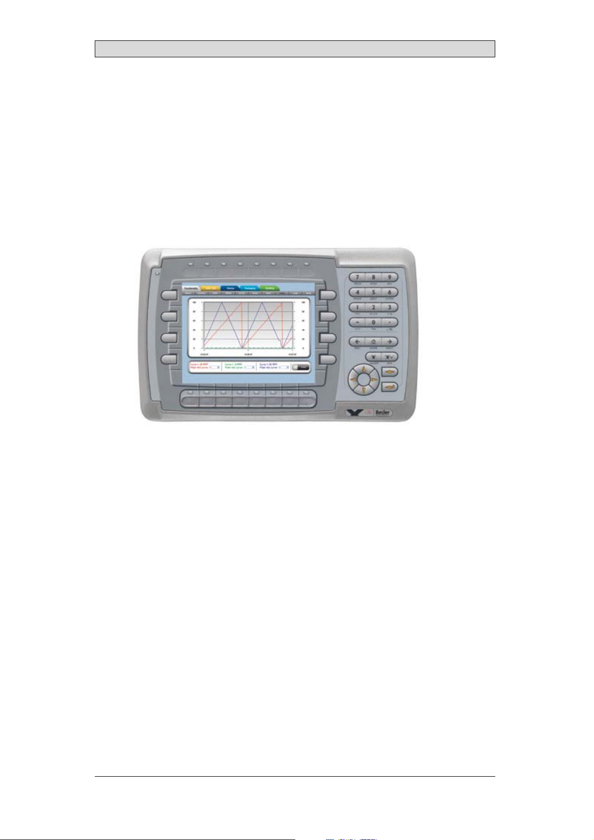
iXPanelK70
Service&MaintenanceManual
MAEN002,2010-05
English
Page 2

Service&MaintenancemanualforiXPanelK70
Foreword
This manual contains detailed information about iX Panel K70, including
descriptions of variousactions that can be carried out in orderto maintain or
update the operator panelhardware and software.
The manual contains descriptionsof basic maintenance and replacement of
common parts in iXPanel K70.
The manual assumes thatthe most recent versions of the system program
(firmware) and iX Developer are used.
The followingother manuals are available for iX Panel K70:
iX PanelK70 installation manual (MAEN996x) for informationregarding
installation.
iX Developer reference manual (MAEN831x) for a description of the
configuration tool.
iX Developer user’sguide (MAEN832x) for function-based descriptions.
Foreword
© Beijer Electronics AB, MAEN002, 2010-05
The information inthis document is subject tochangewithoutnoticeandisprovidedasavailableatthe
time of printing. Beijer Electronics AB reserves the rightto change any information without up dating this
publication. Beijer Electronics AB assumes no responsibility for any errors that mayappear in this document.
Read the entireinstallation manual prior to installing and using this equipment. Only qualified personnel
may install, operate or repairthis equipment. Beijer ElectronicsAB is notresponsible for modified, altered
or renovated equipment. Because the equipment hasa widerangeofapplications,usersmustacquirethe
appropriate know l edge to use the equipment properly in their specific applications. Persons responsible
for the application and the equipment must themselves ensure that each application is in compliance with
all relevant requirements, standards and legislationinrespecttoconfigurationandsafety. Onlypartsand
accessories manufactured according to specifications set byBeijer ElectronicsAB may be used.
BEIJER ELECTRONICSAB SHALL NOTBE LIABLE TO ANYONE
FOR ANY DIRECT, INDIRECT, SPECIAL, INCIDENTAL OR
CONSEQUENTIAL DAMAGESRESULTING FROMTHE
INSTALLATION, USE OR REPAIR OF THISEQUIPMENT, WHETHER
ARISING IN TORT, CONTRACT, OR OTHERWISE. BUYER'SSOLE
REMEDYSHALL BE THE REPAIR, REPLACEMENT, OR REFUND
OF PURCHASE PRICE, ANDTHE CHOICE OF THE APPLICABLE
REMEDYSHALLBEATTHESOLEDISCRETIONOFBEIJER
ELECTRONICSAB .
BeijerElectronics, MAEN002
Page 3

Contents
Contents
1 Safety Precautions ....................................................... 5
1.1 General ...........................................................
1.2 During Installation ..............................................
1.3 During Use .......................................................
1.4 Service and Maintenance ........................................
1.5 Dismantling and Scrapping .....................................
2 Introduction ............................................................. 7
2.1 iX PanelK70 .....................................................
2.2 Maintenance .....................................................
2.3 Serviceand Repairs ..............................................
2.4 Dismantling and Scrapping .....................................
2.5 Contact andSupport ............................................
3 Installation ............................................................... 10
3.1 SpaceRequirements .............................................
3.2 InstallationProcess ..............................................
3.2.1 ConnectionstotheController ........................... .......
3.2.2 OtherConnectionsandPeripherals .............................
4 Technical Data ........................................................... 14
5 Chemical Resistance .................................................... 15
5.1 MetalCasing .....................................................
5.2 Keyboard Material ...............................................
5.2.1 Autotex F157/207 ...................... .........................
5.2.2 Screen Surface ........... ........................................
5.2.3 Autoflex EB .................................................. ....
6 Hardware Tests .......................................................... 18
7 Additional Hardware ................................................... 19
7.1 Memory Card ....................................................
7.1.1 Installation ................................................ .......
7.1.2 SettingsiniXDeveloper ................... ......................
8 Hardware Replacement ................................................. 21
8.1 Mode Switches ...................................................
8.2 Cables .............................................................
8.3 Replacing the Rear Cov
8.4 Replacing the Displa
8.4.1 Self-test of the Disp
er ........................................
y/Display Cable .. ........................
lay ...........................................
8.5 ReplacingtheCompleteFront ..................................
8.6 Replacing the Backlight .........................................
8.7 Available SpareParts for iX Panel K70 ..........................
9 Service Menu ............................................................ 29
9.1 Service Menu in an Empty Panel ...............................
9.2 Service Menu in a Panel withProject ...........................
9.3 ServiceMenuOptions ...........................................
9.3.1 IPSettings ................................................ .......
9.3.2 Date/Time ......... ..............................................
9.3.3 EraseProject ................................................. ....
10
10
13
13
15
16
16
17
17
19
19
20
21
22
23
24
25
26
27
28
29
29
29
29
29
29
5
5
6
6
6
7
8
8
8
9
BeijerElectronics, MAEN002
Page 4

Contents
9.3.4 Format Memory Card ...........................................
30
10 Hardware SelfTest ...................................................... 31
11 AdditionalInstallation Tips ............................................ 32
11.1 Grounding theOperatorPanel .................................
11.2 Ethernet Connection in the Panel ..............................
11.3 To Achieve Better EMC Protection .............................
11.4 Ambient Temperature ...........................................
11.5 Safety .............................................................
11.6 Galvanic Isolation ................................................
11.7 Cable and Bus Termination RS485 .............................
32
33
34
35
36
37
38
12 Fault Tracing ............................................................. 39
13 Software .................................................................. 41
13.1 General Information aboutSoftware ...........................
13.1.1 Software Products .................................. .............
13.2 Update Software .................................................
13.2.1 iXDeveloper ........................................... ..........
13.2.2 Remote AccessViewer ........................ ...................
13.2.3 SystemProgram ............................................. ....
41
41
42
42
42
42
14 Environmental Aspects ................................................. 44
14.1 General Environmental Aspects ................................
14.2 Environmental Impact of the Operator Panels .................
14.2.1 Mechanical Components ........................................
14.2.2 Electronics .................................... ...................
14.3 Recycling .........................................................
14.4 Environmental Impact Report ..................................
44
44
44
44
45
45
BeijerElectronics, MAEN002
Page 5

Safety Precautions
1SafetyPrecautions
Both the installer andthe owner and/or operator of the operator panel must read
and understand thisinstallation manual.
1.1 General
• Read the safety precautionscarefully.
• Check the delivery for transportation damage. If damage is found, notify the
supplier as soon as possible.
• Donot use the operator panel in an environment with high explosive hazards.
• Thesupplier is not responsible for modified,altered or reconstructed
equipment.
• Use only parts and accessories manufactured accordingto specifications of
the supplier.
• Read the installationand operating instructions carefully before installing,
using or repairingthe operator panel.
• Neverallowfluids,metalfilingsorwiringdebristoenteranyopeningsinthe
operator panel. This may cause fire or electrical s hock.
• Only qualified personnel may operate the operator panel.
• Storing theo perator panel where the temperature is lower/higher than
recommended in this manualcan cause the LCD display liquidto
congeal/become isotopic.
• The LCD display liquid contains apowerful irritant. Incase of skin contact,
wash immediately with plenty of water. In case of eye contact, hold the eye
open,flushwithplentyofwaterandgetmedicalattention.
• Thefiguresinthismanualservesanillustrativepurpose. Becauseofthemany
variables associated with anyparticular installation, the supplier cannot
assume responsibility for actual use based on the figures.
• The supplier neither guarantees that the operatorpanel is suitable for your
particular application, nor assumesresponsibility for your product design,
installation or operation.
1.2 DuringInstallation
• The operator panelis designed for stationary installation on a plane surface,
where thefollowing conditions arefulfilled:
– no high explosive risks
– no strong magnetic fields
– no direct sunlight
– no large, sudden temperature changes
• Install the product according to the accompanying installation instructions.
• Ground theproduct according to the accompanying installation instructions.
• Only qualified personnel mayinstall the operator panel.
• Separate the high voltage, signal and supply cables.
• Make surethat the voltage and polarity of the power source is correctbefore
connecting theproduct to the power outlet.
• Peripheralequipment must be appropriate for theapplication and location.
BeijerElectronics, MAEN002
5
Page 6

Safety Precautions
1.3 DuringUse
• Keep the operator panel clean.
• Emergency stop and othersafety functions may not be controlled from the
operator panel.
• Do not usetoo much force or sharp objects when touching the keys, touch
screenetc.
1.4 ServiceandMaintenance
• Only qualified personnel should carry out repairs.
• The agreed warranty applies.
• Before carrying out any cleaning or maintenanceoperations, disconnect the
equipment from theelectrical supply.
• Clean the display andsurrounding front cover with a soft cloth and mild
detergent.
• Replacing the battery incorrectly may resultin explosion. Only use batteries
recommended by thesupplier.
1.5 DismantlingandScrapping
• The operator panelor parts thereof shall be recycledacc
regulations.
• The followingcomponents contain substances t
to health andthe environment: lithiumbatter
display.
hat might be hazardous
y, electrolytic capacitor and
ording to local
BeijerElectronics, MAEN002
6
Page 7
Introduction
2Introduction
This manual describes how tomaintain the iX Panel K70.
The functions availablein iX Developer depend on which operator panel model is
used.
2.1 iXPanelK70
The followingdrawings are available foriX Panel K70:
• Outline drawing
• Panelcut-out
• Te x t s t ri p
BeijerElectronics, MAEN002
7
Page 8

Introduction
2.2 Maintenance
Carefully read the instructions beforebeginning maintenance on the operator
panel.
• Only qualified personnel should carry out maintenance.
• The agreed warranty and license agreements apply.
• Any damage tothe operator panel caused by personnelinvalidates the
warranty.
• Before carrying out any cleaning or maintenanceoperations, disconnect the
operator panel fromthe power supply.
• Clean the display andsurrounding front cover with a soft cloth and mild
detergent. Recommended cleaning fluids for the display are water and IPA
(Isopropyl Alcohol or Hexane).
• Replacing the battery incorrectly may resultin explosion. Only use batteries
recommended by thesupplier.
• A 6-month warrantyon all service parts is provided.
Maintenance personnel are permitted tocarry out the following actions:
• Replacing the Rear Cover
• Replacing the Display/Display Cable
• Replacing the Complete Front
2.3 ServiceandR epairs
• Only accredited companies are permitted to perform service and repairs.
• Ifanon-accreditedcompanyconductsanykindofserviceorrepair,theagreed
warranty will beinvalidated.
• If training is required,contact the supplier.
• All maintenance should be performed in a15-30 °C temperature range.
• Any damage tothe operator panel caused by personnelinvalidates the
warranty.
• Contracts with customers s upersede the information in this document.
2.4 DismantlingandScrapping
• The operator panel,or parts thereof, should berecycled according to local
regulations.
• The followingcomponents contain substances that mightbe hazardous to
health and theenvironment: lithium battery, electrolyticcapacitor, display.
BeijerElectronics, MAEN002
8
Page 9

Introduction
2.5 ContactandSupport
If you wantto report a fault or have aquestion about the operator panels, please
contact your localsupplier or fill out the form on the web site.
1.
Enter the web site www.beijerelectronics.com and selectSupport.
2.
Select Contact inthe menu. Make sure to provideinformation about type
number, serial number, environmentand an installation description.
The form will besent to the manufacturer’s help deskand they will answer your
question or registeryour improvement/fault.
To ensure quick resolution, provideas many details as possible in yourreport.
Include the date and time when the problem occurred, a description of what you
were trying to do, thedetailed steps you took that led up to the problem, and
details about any error messages received.
BeijerElectronics, MAEN002
9
Page 10
3Installation
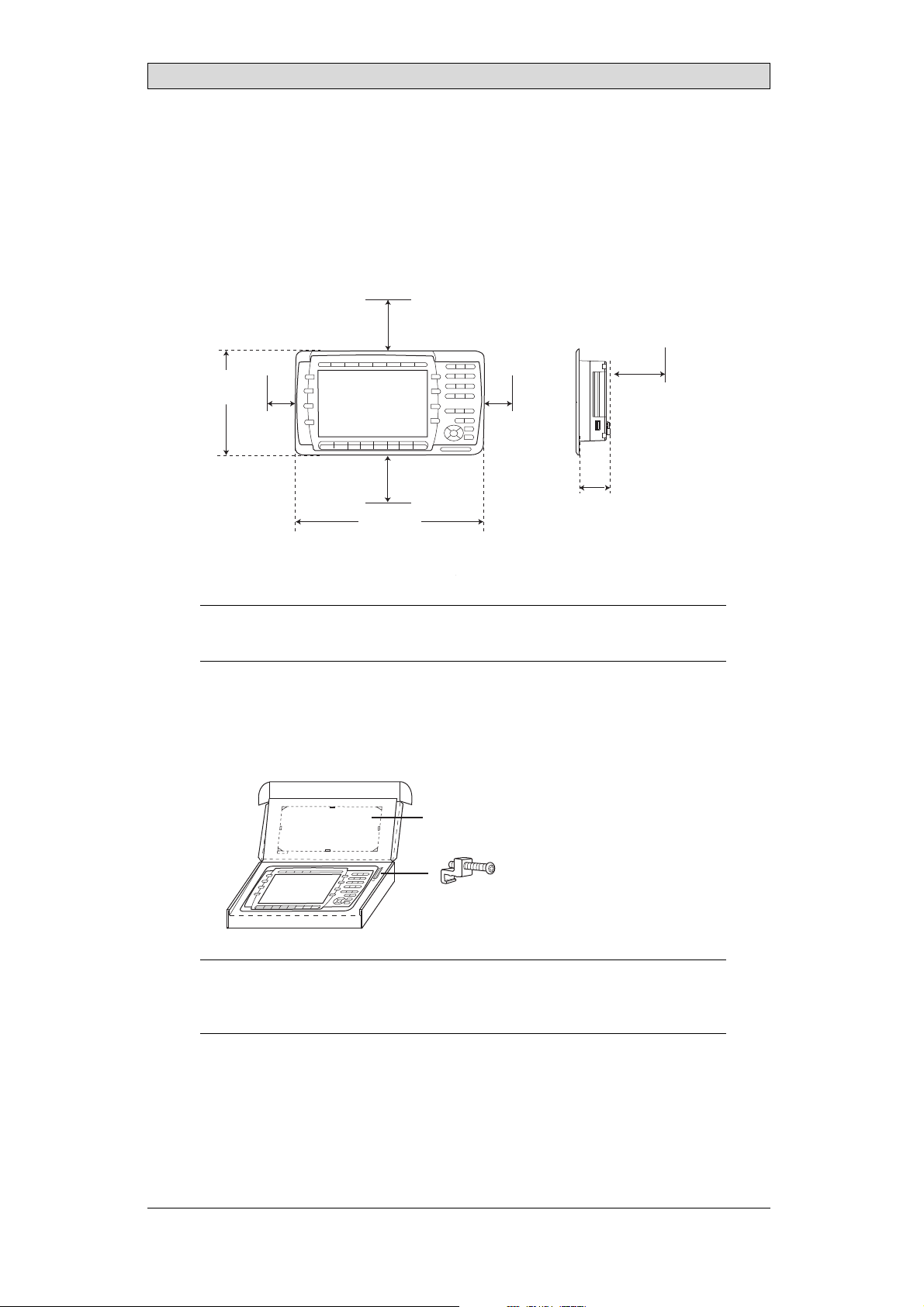
3.1 SpaceRequirements
• Installation plate thickness: 1.5 - 9.0mm (0.06 - 0.35 inch)
• Space requirementswhen installing the operator panel:
100 mm
(4.0 inch)
Installation
177 mm
(6.97 inch)
50 mm
(2.0 inch)
100 mm
(4.0 inch)
285 mm
(11.22 inch)
Caution:
Theopenings ontheenclosureareforairconvection. Donotcover theseopenings.
50 mm
(2.0 inch)
(2.20 inch)
100 mm
(4.0 inch)
56 mm
3.2 InstallationProcess
1.
Unpackand check the delivery. If damage is found, notify thesupplier.
Panel cut out 245.5 x 138.5 mm
(9.67 x 5.45 inch)
x 6
Note:
Placethe operatorpanelonastablesurfaceduringinstallation.
Droppingitorlettingitfallmaycausedamage.
BeijerElectronics, MAEN002
10
Page 11
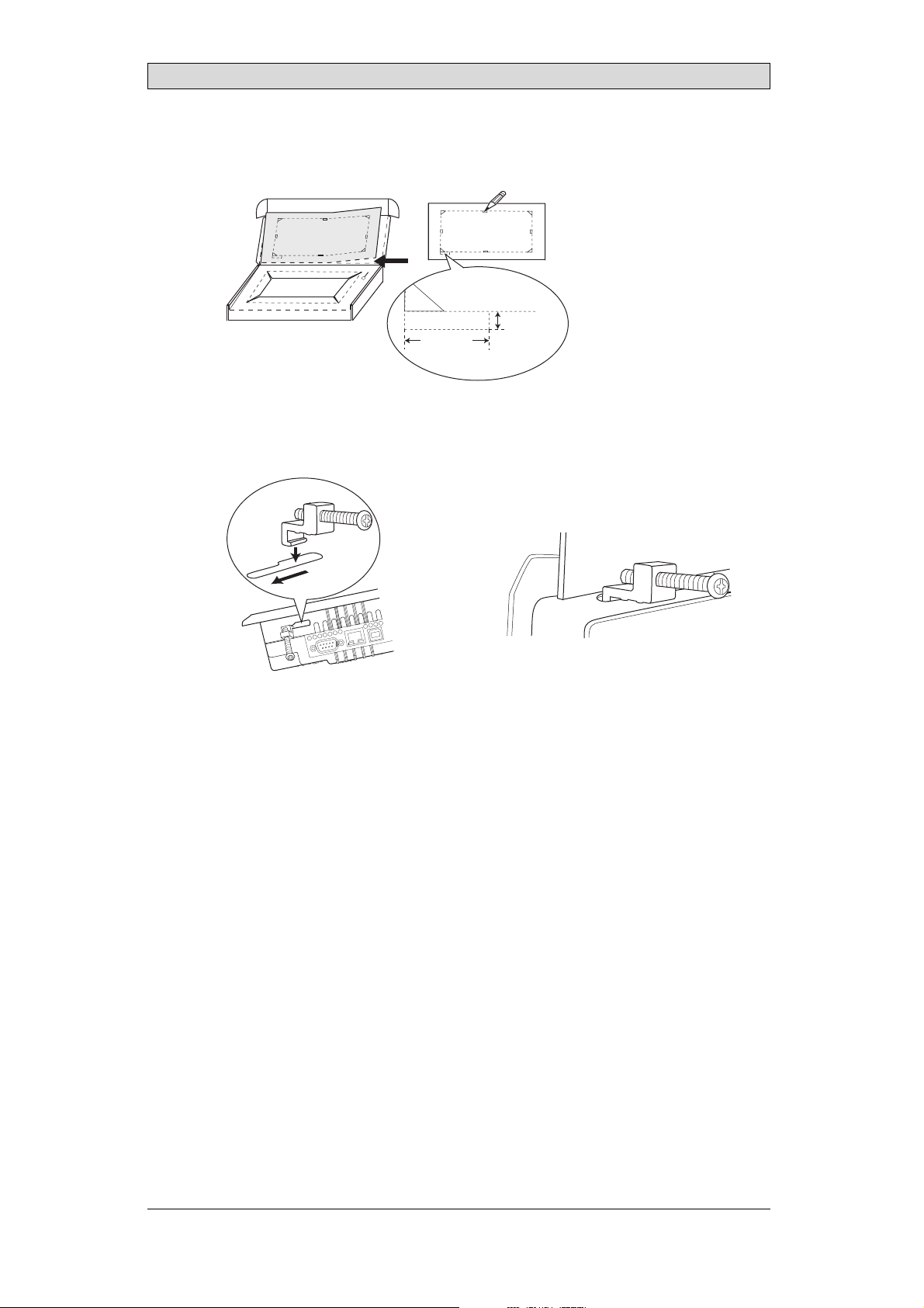
2.
Place thepanel cut out where theoperator panel is to besituated, draw along
the outer sides of the holes and cutaccording to the markings.
For text strip
5.0 mm
18.0 mm
(0.71 inch)
3.
Secure the operator panel in position, using allthe fastening holes and the
(0.20 inch)
provided brackets and screws:
Installation
x 6
0.5 - 1.0 Nm
BeijerElectronics, MAEN002
11
Page 12
Installation
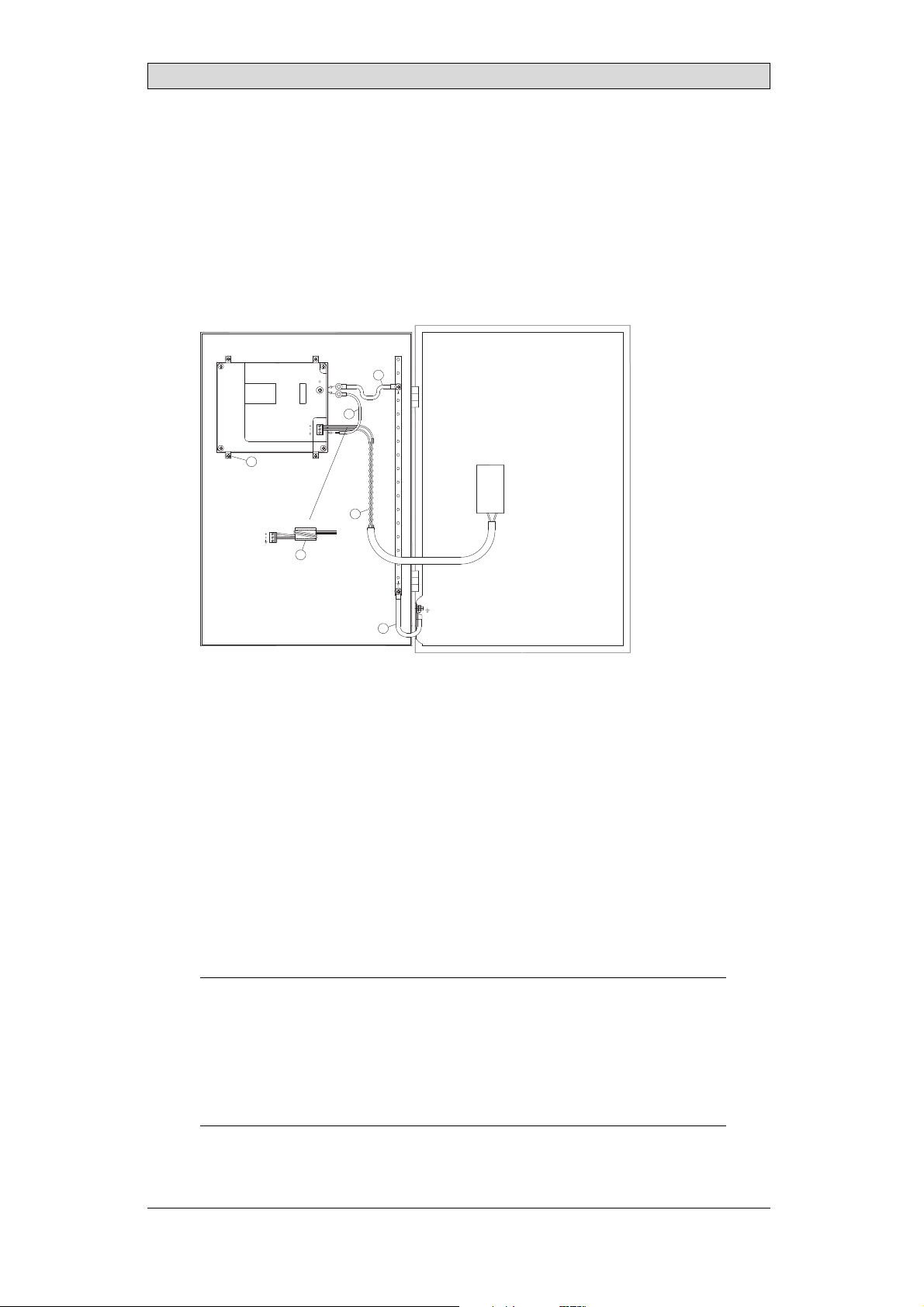
4.
Connect the cables in the specified order, according to the drawing and steps
below.
Caution:
• Ensurethattheoperatorpanelandthecontrollersystemhavethesameelectrical
grounding(referencevoltagelevel),otherwiseerrors incommunicationmay
occur.
• Theoperatorpanelmustbebroughttoambienttemperaturebeforeitisstarted
up. Ifcondensationforms,ensurethattheoperatorpanelisdrybeforeconnecting
itto thepoweroutlet.
• Ensurethatthevoltageandpolarityofthepowersourceiscorrect.
• Useonly shieldedcommunicationcables.
• Separatehighvoltagecablesfromsignalandsupplycables.
Power
CF CARD
B
1
Controller
RS422/RS485
RS232
24V DC
24V DC
C
D
A
Ethernet
– Connect cable A.
– Connect cable B, using an M5 screwand a grounding conductor (as short
as possible) with a cross-section of minimum 2.5 mm
– Connect cable C.
– Connect cable D.
5.
Carefully removethe laminated film over the operator panel display, to avoid
2
.
static electricity that could damage the panel.
BeijerElectronics, MAEN002
12
Page 13

Installation
3.2.1 ConnectionstotheController
Forinformation about the cables to be used when connecting the operator panel to
the controller,please refer to the help file for the driver in question.
3.2.2 OtherConnectionsandPeripherals
Cables, peripheral equipment and accessories must besuitable for the application
and its environment. Forfurther details or recommendations, please refer to the
supplier.
Caution:
Whenusingacompactflashcard, donotremovethecardwhenthebusyindicator is
illuminated.
BeijerElectronics, MAEN002
13
Page 14
Technical Data
4TechnicalData
Parameter iX Panel K70
Frontpanel,WxHxD 285x177x6mm
Mountingdepth 56mm (156mmincludingclearance)
Frontpanel seal IP66
Rear panel seal IP 20
Keyboardmaterial Membraneswitchkeyboardwith metaldomes. Overlay
filmof AutotexF157*withprintonreverseside. 1million
operations.
Reverseside
material
Weight 1.4 kg
Serialport
RS422/RS485
SerialportRS232C 9-pin D-sub contact,male withstandardlockingscrews4-40
Ethernet ShieldedRJ45
USB HosttypeA(USB 1.1),max outputcurrent 500m A
CF-slot Compactflash,typeI andII
Realtimeclock ±20PPM +errorbecauseofambienttemperatureandsupply
Power consumption
atrated voltage
Display TFT-LCD.640x480pixels,64Kcolors.
Activeareaof
display, WxH
Fuse InternalDCfuse,3.15AT,5 x20mm
Powersupply +24V DC(20-30VDC).Powersupplyconnector.
Ambient
temperature
Storagetemperature -20° to+70°C
Relativehumidity 5- 85%non-condensed
Approvalsand
certifications
Powder-coatedaluminum
25-pinD-sub contact,chassis-mountedfemalewith
standardlo cking screws4-40UNC
UNC
DevicetypeB(USB1.1)
voltage. Totalmaximumerror: 1min/monthat25°C.
Temperature coefficient: -0.034±0.006ppm/°C
Rechargeablebattery.
Normal: 0.4A
Maximum: 0.9A
CCFLbacklight lifetimeat theambienttemperatureof
+25°C:>50,000h.
131.5x 98.6m m
CE:The powersupplymustconformwiththerequirements
accordingtoIEC60950andIEC 61558-2-4.
ULand cUL:Thepowersupplymustconformwith the
requirementsforclassIIpowersupplies.
Verticalinstallation: 0°to+50°C
Horizontalinstallation: 0°to +40°C
Informationisavailableon thewebsite
www.beijerelectronics.com
2
*SeesectionChemical Resistancefor moreinformation.
BeijerElectronics, MAEN002
14
Page 15
Chemical Resistance
5 ChemicalResistance
5.1 MetalCasing
The frame andcasing material is powder-coated aluminum. This powder paint
withstands exposure to the following chemicals without visible change:
Aceticacid 10% Phosphoricacid4%
Citricacid10% Phosphoricacid10%
Diesel Seawater
Distilledw ater Sodiumchloride2%
Edibleoil Sodiumchloride20%
Fueloil Sulphuricacid 20%
Hydrogenperoxide3% Tapwater
The powderpaint shows limited resistance to the f
ollowing chemicals atroom
temperature:
Butanol Nitricacid3%
Hydrochloricacid5% Nitricacid10%
Isopropylalcohol Phosphoricacid43%
Na-hypochlorite10% Turpentine
Note:
Ifexposureto anyofthe abovechemicalsisdemanded,itisrecommendedtofirsttest
thechemical onan“invisible”spotofthemetalcasing.
Thepowderpaintshowslittleornoresistancetothefollowingchemicalsatroom
temperature:
Aceticacid, conc. Methyl-ethylketone Toluene
Acetone Nitricacid 30% Trichlorethylene
Ammonia5% Phenol Xylene
Ammonia,conc. Sodiumhydroxide5% 97octanunleadedpetrol
Ethylacetate Sodiumhydroxide30% 98octanle ad edpetrol
BeijerElectronics, MAEN002
15
Page 16
Chemical Resistance
5.2 KeyboardMaterial
5.2.1 AutotexF157/207
Autotex F157 or F207 covers the overlay surrounding thescreen.
SolventResistance
Autotex F157/F207 withstands exposure of more than 24hours duration under
DIN42115Part2tothefollowingchemicalswithoutvisiblechange:
Acetonitrile DieselDowney/Lenor
Ajax/ Vimin solution EthanolPotassiumferricyanide
Alkalicarbonatesolution1Glycerine Potassiumhydroxide
Ammonia(<40%)
Aceticacid (<50%) Gumption
Arielpowderinsolution
1
Bleach
Castoroil Methanol Trichloroaceticacid
Causticsoda(<40%)
Cuttingoil Paraffinoil Windex
Cyclohexanol Persilpowderinsolution1Wisk
Diacetonealcohol Petroleumspirit
1
Extremely faint glossing of the texture was noted.
1
1
Glycol PureTurpentine
1
1
Hydrochloricacid(<36%) Sulfuricacid (<10%)
Linseedoil Tomatoketchup
Nitricacid (<10%) WhiteSpirit
1
Phosphoricacid(<30%)
(<30%)
SBP60/95
(<50%)
1
-
1
1
Autotex withstands DIN 42 115Part 2 exposure of up to1 hour duration to glacial
acetic acid withoutvisible change.
Autotex is no
t resistant tohigh pressure steam at over 100 °C or the following
chemicals:
Concentratedmineralacids Benzylalcohol
Concentratedcaustic solution Methylenechloride
OutdoorUse
In common with all polyester based films AutotexF157/F207 is not suitable for
use in conditions of long term exposure to directsunlight.
BeijerElectronics, MAEN002
16
Page 17

Chemical Resistance
5.2.2 ScreenSurface
The screen surface on the panel withstands exposure to the following solvents
without visible change:
Solvents Time
Acetone 10minutes
Isopropanol 10minutes
Toluene 5 hours
5.2.3 AutoflexEB
It isrecommended to use the AutoflexEB key protection sheet, that can be ordered
from Beijer Electronics.
SolventResistance
Autoflex EB withstands exposure to the same chemicals as Autotex F157 or F207
according to section AutotexF157/207.
OutdoorUse
In common withall polyester based films Autotex EBis not suitable for use in
conditions of long term exposure to direct sunlight.
BeijerElectronics, MAEN002
17
Page 18

Hardware Tests
6 HardwareTests
Before the operator panels are approved for m arket introduction, they are tested
by independent authorities. The iX Panelsare examined by several authorities
before being approvedfor market introduction. All operator panels are designed
to fulfill standards such as CE. The quality policy and environmental policy place
demands on all suppliersand subcontractors.
The manufacturer performs extensive hardware testing before an operator panel
is approved. Some tests are performed byexternal testing companies, such as
the SwedishNational Testing andResearch Institute. All operator panels are
submitted to testingbefore leaving the manufacturer.
BeijerElectronics, MAEN002
18
Page 19

Additional Hardware
7 AdditionalHardware
7.1 MemoryCard
An internalCompact Flash memory cardcan be used in iX PanelK70 for
expansion of theproject memory.
Note:
Whenusinganinternal CompactFlashmemorycard,noexternalCompactFlash
memorycardcanbeused. AnexternalUSBFlashdrivecanbeusedforthesame
functionsasanexternalCompactFlashcard.
Compact Flash cards of type I and II are supported.
Compact Flash cards of the following brands and models are recommended:
SiliconSystemsSiliconDrive
SanDiskIndustrialGrade
Cactus203-,302-and303–series
Other Compact Flashcards may be approvedas accessories for the iXPanels even
if they are not present in theabove list, due to product changes and upcoming
brands.
7.1.1 Installation
Performthe following steps to install an internal Compact Flash card inthe
operator panel:
1.
Turn off the powerto the panel.
Note:
MakesuretouseadequateESDprotection.
2.
Followthe instructions in the Replacing the Rear Cover section to removethe
rear cover.
3.
Flipthe back cover;the CPU boardis mounted insidethe back cover.
4.
Insert the CompactFlash memory card in its sloton the CPU board.
memory card slot
BeijerElectronics, MAEN002
19
Page 20

Additional Hardware
5.
Re-attach the backcover to the operator panel.
6.
Turn on the power to the operator panel.
When the operator panel starts up, you will be askedif you like to move the
files to the internal card; select YES to this question.
7.1.2 SettingsiniXDeveloper
The size of theinternal memory card mustbe entered in iX Developer.
1.
Click on Settingson the Project group of the Project ribbon tab.
2.
Select the Display/Panel properties.
The sizeof the internal memory cardis stated underMemory Card.
BeijerElectronics, MAEN002
20
Page 21
Hardware Replacement
8 HardwareReplacement
This section containsinstructions on how to replace operatorpanel hardware.
Only componentsincluded in the latest billof material and spareparts list are
allowed. See Available Spare Parts for iX Panel K70.
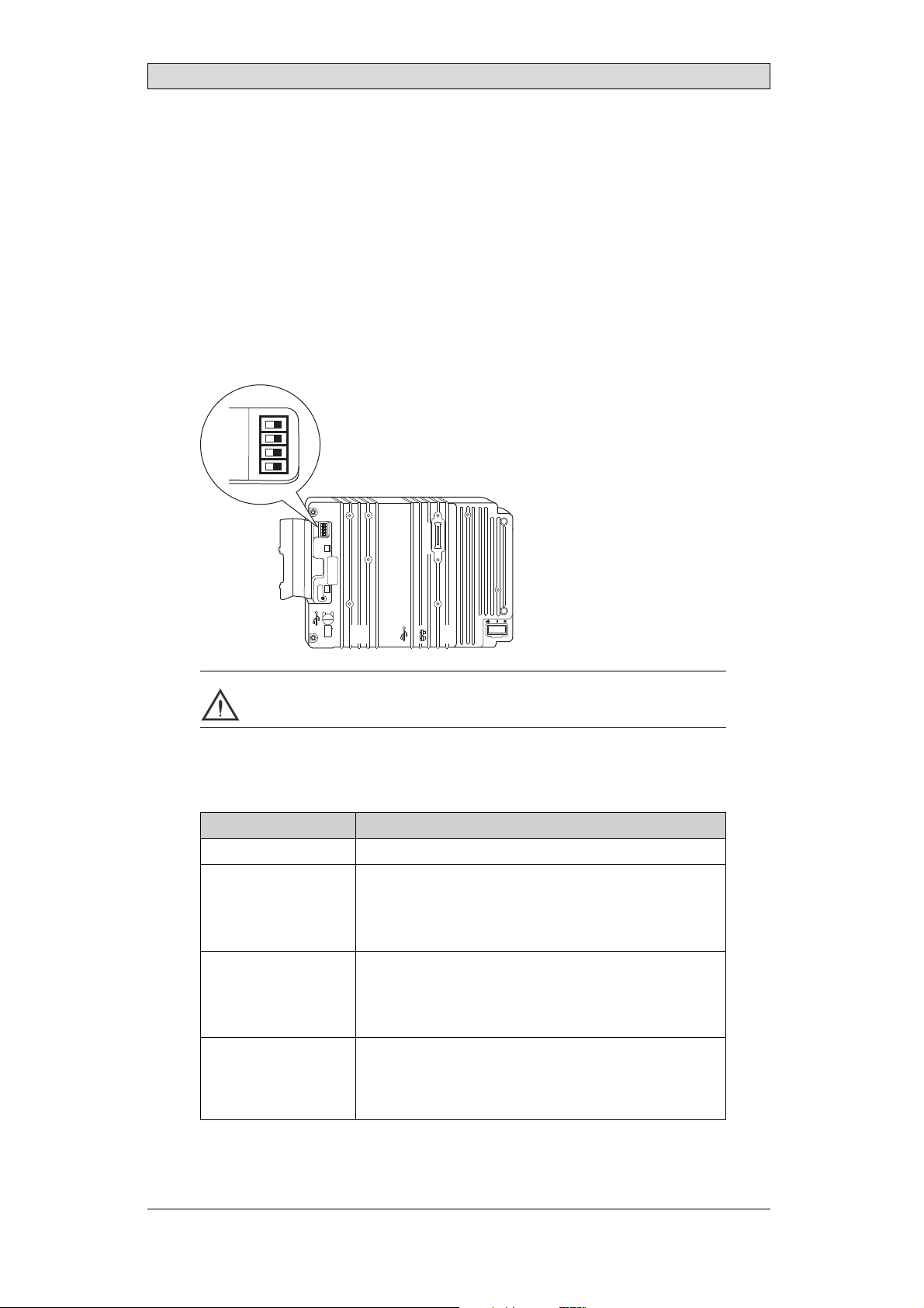
8.1 ModeSwitches
The iX Panel K70 has fourmode switches (DIP switches) located on therear side
of the operatorpanel.
1 2 3 4
MODE
ON DIP
10/100
EXPANSION
RS232
COM 2
24V DC
1
1 2 3 4
MODE
ON DIP
CF CARD
BUSY
COM 1
RS422
RS485
Warning:
Themodes belowaretobeusedwithcaution.
Themodeswitcheshavethefollowingfunctions: 1=ON,0=OFF
Each letter in“MODE” has a corresponding mode switch.
MODE Description
0000 “Runmode”-bootsCE,normal operation.
0010 SystemRestore,resetsthefilesystemandregistry,
reinstallsthe systemprogram(OPsys_bxxx.CAB).Restores
theoperatorpanel tofactorysettings.
Warning! Informationcaneasilyaccidentlybelost.
0100 ImageLoad mode(Sysload)allowsupgradingofthe
firmwareintheoperatorpanel.
Note: Allfilesincludingthefilesystemintheoperator
panelwillbe deletedwhenupgradingwithImage Loader.
1000 ServiceMenumode,the servicemenuforthesystem
programisshown. AllowstheusertosetIPconfiguration,
erasethe project,calibratethetouchscreenetc. See
sectionService Menufor details.
BeijerElectronics, MAEN002
21
Page 22

Hardware Replacement
MODE Description
1100 Notused (runmode).
1110 Self-test.
xxx1 Hardreset(forcesthe systemtorese t).
To change mode switches, follow the steps below:
1.
Disconnect powerfrom the operator panel.
2.
Set the mode switches using a ballpoint pen.
3.
Reconnect powerto the operator panel.
8.2 Cables
Mostoftheoperatorpanelsusethesametypeofflexcableconnectors.
connector flanges
Flex cable connector
To release the flex cables from the connector, gently push the twoflanges on the
cable connector towards the flex cable.
Note:
Theconnectorsmustbeunlockedonbothsidesbeforeremovingthecable,otherwise
theflexcablemaybedamaged.
BeijerElectronics, MAEN002
22
Page 23

Hardware Replacement
8.3 ReplacingtheRearCover
The followingis needed:
• Anewrearcover,seeAvailable Spare Parts for iX Panel K70
• AtorxT10screwdriver
Note:
MakesuretouseadequateESDprotection.
Follow the stepsbelow to replacethe rear cover:
1.
Poweroff the operator panel.
2.
Remove the rear cover of the operator panel by loosening the 4 torx screws.
4 x torx screws
3.
Re-assemble withthe new rear coverin reverse order.
BeijerElectronics, MAEN002
23
Page 24

Hardware Replacement
8.4 ReplacingtheDisplay/Display Cable
The followingis needed:
• A new display including plasticframe and display cable, see
Available Spare Parts for iX Panel K70
• AtorxT10screwdriver
Note:
MakesuretouseadequateESDprotection.
Followthe steps belowto replace the display/displaycable:
1.
Poweroff the operator panel.
2.
Followthe instructions under Replacing the Rear Cover to remove the rear
cover.
3.
Disconnect the three flex cables from the power card, according to the
illustration below, and removethe two plastic nuts that hold the powercard
in place.
plastic nut
flex cables
plastic nut
4.
Lift the powercard and gently remove thebacklight cable from the rear side.
guide pins
backlight cable
guide pins
snap-in closure for plastic frame
5.
Gently loosen the complete plastic frame anddisplay from the front plate.
Scrap the displayand frame.
6.
Mountthe new display/display cable and frame and re-assemblethe complete
operator panel. Make sure theguide pins ontheframeareproperlyfastenedin
theholesinthefrontplate.
BeijerElectronics, MAEN002
24
Page 25

Hardware Replacement
8.4.1 Self-testoftheDisplay
To perform a self-test of the display, follow thesteps below:
1.
Start theoperator panel in a self-test mode (see table in the
Mode Switches section).
2.
Go to the displaytest. Verify thatthe display works.
3.
If the screendoes not work, try fault tracing, seethe Fault Tracing section.
BeijerElectronics, MAEN002
25
Page 26

Hardware Replacement
8.5 ReplacingtheCompleteFront
The followingis needed:
• Anewfront,seeAvailable Spare Parts for iX Panel K70
• AtorxT10screwdriver
Note:
MakesuretouseadequateESDprotection.
Followthe steps belowto replace the completefront of the iX Panel K70:
1.
Poweroff the operator panel.
2.
Followthe steps 1-3 and 5 in the Replacing the Display/Display Cable instructions, but in step 3, do not remove thedisplay cable .
3.
Attach the new front.
4.
Re-assemble the unit.
BeijerElectronics, MAEN002
26
Page 27

Hardware Replacement
8.6 ReplacingtheBacklight
If the backlight of the iX Panel K70 is broken, theentire display must be replaced.
To replace the display you will needa new display including plastic frame and display cable, see the Available Spare Parts for iX Panel K70 section. Forinformation
about changingthe display, see theReplacing the Display/Display Cable section.
BeijerElectronics, MAEN002
27
Page 28

Hardware Replacement
8.7 AvailableSparePartsforiXPanel K70
Ordernumber Description
601009275 COMPLETEFRONT
Includingfrontcover,glass,keyboard,gasketsandlabels
601009014 DISPLAY
Includingframeandcable
N/A BACKLIGHT
Isnot replaceable. Changethecompletedisplay.
601009015 DISPLAY CABLE
321099040 POWERCONNECTOR
601009011 REARCOVER
601009003 CFCOVER
601009001 MOUNTINGBRACKETS
601009055 KEYPROTECTIONSHEET
601009267 FRONTLABEL
601009122 COMPLETEBOX
601009008 TESTPLUGETHERNET
EthernetRJ45testconnector
601009006 TESTPLUGRS232
RS232test connector
601009007 TESTPLUGRS422/485
RS422/485testconnector
601009004 TESTPLUGUSBH-D
USBH ost andDevicetestconnector
601009069 TESTPLUGUSBH
USBHosttestconnector
BeijerElectronics, MAEN002
28
Page 29

Service Menu
9ServiceMenu
The service menu for theoperator panel can be accessed beforea project is
downloaded, or by settingthe mode switches in mode 1000. The location of the
mode switches is described in the Mode Switches section.
9.1 ServiceMenuinanEmptyPanel
When no project isloaded in the panel memory,the panel will boot, displayingthe
Welcome screen. Press anywhere onthe panel display to enter the service menu.
9.2 ServiceMenuinaPanelwith Project
When a project is loaded in the panel memory, the panel will automatically start to
execute theproject. To display the service menu atboot-up:
1.
Disconnect the powersupply from the panel.
2.
Set the mode switches in mode 1000 (Service Menu mode).
3.
Connect the powersupply.
4.
Make desiredsettings in the service menu.
5.
Disconnect the powersupply from the panel.
6.
Set themode switches in mode 0000 (Run mode).
7.
Reconnect thepower supply.
9.3 ServiceMenuOptions
The followingoptions are available in the Service Menu:
9.3.1 IPSettings
Select to obtain an IP address automa
The IP addresscan also be set during
9.3.2 Date/Time
Use the Date/Time Settingsdialog to set the time zone, date and time for the
panel.
9.3.3 EraseProject
The erase functionwill detect if the project is located in the panel memory or on a
memory card. Pressing Erase Project will completely removethe project and all its
components from the panelmemory/the memory card.
tically via DHCP, or specify an IP address.
project transfer.
BeijerElectronics, MAEN002
29
Page 30

Service Menu
9.3.4 FormatMemoryCard
The format memory cardfunction will detect if externaland internal memory
cards. Select which card to formatand, in some cases, formatting alternatives.
BeijerElectronics, MAEN002
30
Page 31

Hardware Self Test
10 HardwareSelfTest
The self-test program can be used to test aspects of operator panel functionality
and thecommunication ports. To run the testyou will need:
• Test plugs; see Te st pl ug dr aw i ng .
• 24 V DC, min. 3 A.
Followthe steps below to run the self-test program onthe operator panel:
1.
Poweroff the operator panel.
2.
Go to the self-test. Setthe mode switches to the self-testpositions, see the table
in the Mode Switches section.
3.
Power on the operator paneland follow the instructions at the bottom of the
display.
4.
When using thetest plugs, make sure all LEDs on the 9-pin and 25-pin
D-subs areon.
5.
When the self-testis finished, power off the operator panel and set all mode
switches tothe OFF position.
If an erroroccurs during the self-test, try to fault trace. See Fault Traci
ng.
BeijerElectronics, MAEN002
31
Page 32
Additional InstallationTips
11 AdditionalInstallationTips
When experiencing communication problems in for examplenoisy environments
or when operating close to temperaturelimits, the following recommendations
are to be noticed.
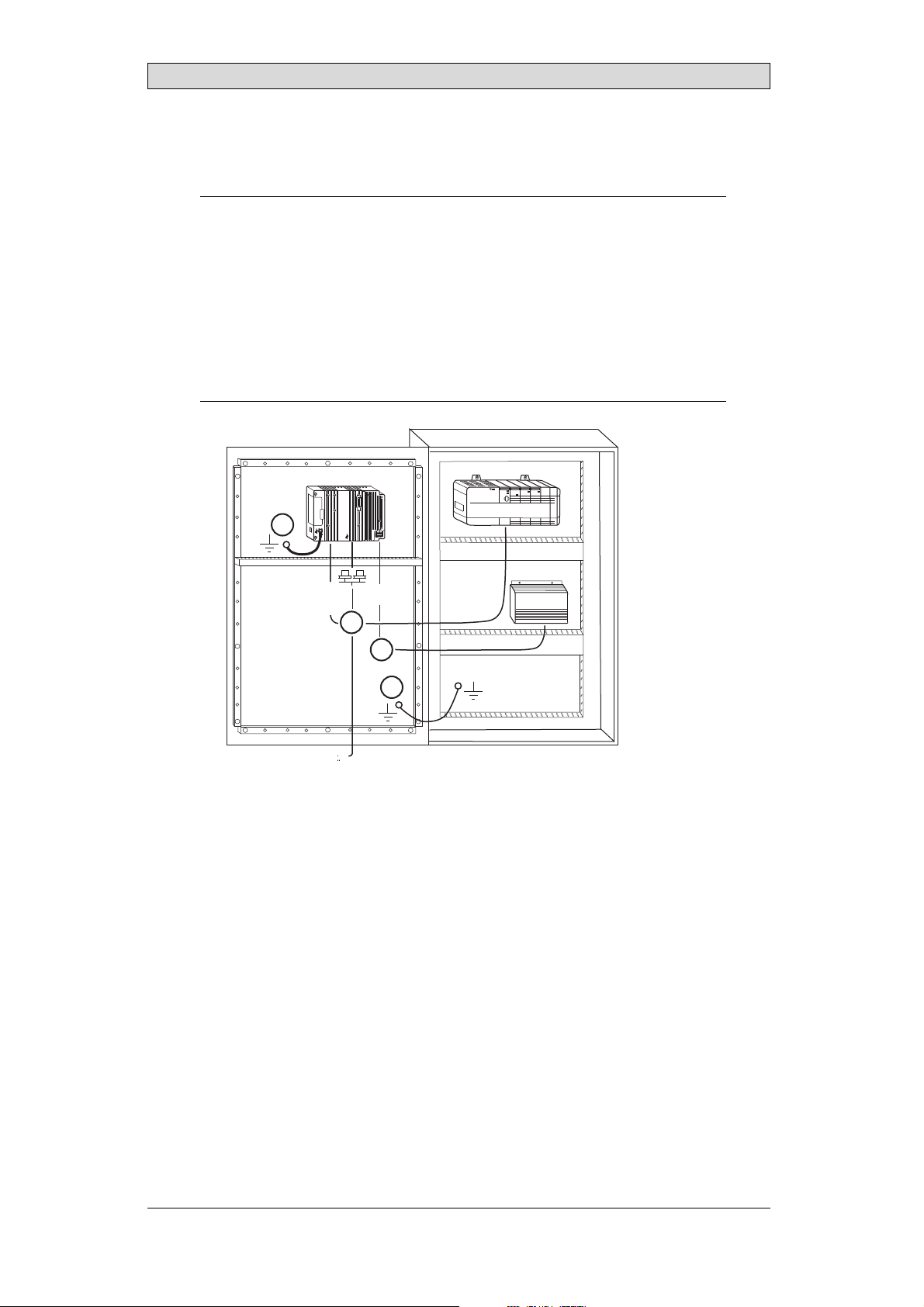
11.1 GroundingtheOperatorPanel
Door
Operator panel
1
Ferrite core
3
2
5
6
4
Mounting plate in the cabinet
Power supply
24 V DC
5350
The operator panel’s mounting clamps do not provide a securegrounding
connection between the panel and the device cabinet, see 1 in drawing above.
1.
Connect a 2.5 mm
and the panel chassis, see 2 in drawi
2.
Connect a 6 or 4mm
2
wire betweenthe ope
rator panel’s quick-connect plinth
ng above.
2
wire or groundingbraid between the panel’s chassis and
the closest grounding p oint on the door,see 3 in drawing above.
3.
Connect a strong but short grounding braid between the door and the device
cabinet,see 4 in drawing above.
4.
Twist the cables onto the 24 V DC feed, see 5 in drawing above.
2 turns aroundthe ferrite core provide4 times the suppression of 1turn.
3 turns aroundthe ferrite core provide9 times the suppression of 1turn.
A ferrite core suppresses disturbances to the 24 V feed, see 6 in drawing above.
Note:
Thegroundingwiress hould beshortandtheconductorshouldh ave alargearea.
Along, thingroundingwirehasaveryhighimpedance(resistance)athighfrequencies
andwill notguidedisturbancestotheground.
Multi-wireconductors arebetterthansinglewireconductorswiththesamearea.
Abraidedconductorwirewith thesameareaisevenbetter. Thebestisashort, thick
groundingbraid.
BeijerElectronics, MAEN002
32
Page 33

Additional InstallationTips
11.2 EthernetConnectioninthePanel
Industrial Ethernet
RJ45
RJ45
RJ45
RJ45
Operator panel
RJ45
1
2
Operator panel
RJ45
Operator panel
RJ45
Operator panel
RJ45
5351
Shielded
0.1 uF
250 V
3
4
1-1
2-2
3-3
8-8
Short and
unshielded
5
In some industrialunits for Ethernet, the RJ45 contact’s shield is connected to the
chassis via a capacitor, see1 in drawing above.
The operator panel’s Ethernet shield is directly
connected to the chassis, see 2 in
drawing above.
1.
Check whether the other Ethernetunit has its shield directly grounded or
grounded via a capacitor.
Note:
Inmanycases,connecting theshieldedEthernetcablingtothechassisatbothendsis
inappropriate. Humo r groundingloopscanoccur. Unshielded cablingmayeven result
infewercommunicationerrors.
A good solution may be to use a shielded Ethernet cable, but toconnect the shield
at one end only.
One option isto break the shield, see 3 in drawingabove.
A more elegantmethod is to expand the shielded Ethernet cabling with a piece of
unshielded Ethernetcable, see 4 in drawing above.
You can ground the shield via an external 0.1 uF/250 V plastic capacitor, see 5 in
drawing above. This will connect theHF transients to the ground.
BeijerElectronics, MAEN002
33
Page 34

Additional InstallationTips
11.3 ToAchieveBetterEMCProtection
• Initially,use the original cabling from BeijerElectronics primarily.
• Use shielded cables for RS232 communication.
• Use twisted pair andshielded cabling for RS422 and RS485.
• Use the cabling intended for the bus type; Ethernet,Profibus, CC-Link,
CAN, Device Netetc.
• Install and connect according to applicablespecifications for the relevant bus
standard.
• Use shielded cabling forEthernet, preferably with foil + braided shield.
• D-sub covers should be shielded, and the shield should be connected to the
cover 360° where the cable comes in.
• Connect the shield at both ends.
Shielded cable
0.1 uF/250 V
Ground plane 1 Ground plane 2
Ground plate Ground plate
Not same potential
in another building
5352
With longer distances, thereis a risk that the ground potential may bedifferent.
In that case, the shieldshould only be connected at one end. A good alternative
is to connect the ot her end of the shield to the ground viaa 0.1 uF/250 V plastic
capacitor. Both ends are then connected to the ground in terms of HF, but only
connected to the ground at one end in terms of LF, thus avoidingthe 50 Hz
grounding loops.
Metal cabinet Metal cabinet
Terminal or connector Terminal or connector
Cable clamp
in steel
Short distance
EMC cable gland Plastic cable gland
Shielded cable Shielded cable
1.
Usean EMC cable gland or regular plastic cable gland, removethe outer jacket
5353
and connect theshield to the installation plate with a360 ° metal cable clamp.
2.
Place the 24V DC and communications cabling in one cable trunk/cable duct
and 230/380 V AC in another. If the cables need to be crossed, cross them at
90 ° only. Avoidcombining the cabling for stronger 24 V DC outputs with
the communication cabling.
Ferritecores that are snappedonto the shielded cabling m ay remove minor
disturbances. Large ferrite pieces that aresnapped onto unshielded cabling and
where the wiresgo 2-4 times around the cores are approximately 5-25 timesmore
efficient.
BeijerElectronics, MAEN002
34
Page 35

Additional InstallationTips
11.4 AmbientTemperature
The maximum ambient temperature for the operator panel is providedin the
specifications. The ambient temperature refers to the temperature inthe device
cabinet which cools the panel’s electronics.
Top
50 °C inside
Operator
panel
30 °C outside
Middle
45 °C inside
Bottom
40 °C inside
Power
Power
Power
Axial fan
120 x 120 mm
Airflow
5354
Inmostcases,theambienttemperaturefortheoperatorpanelissignificantly
higher than the device cabinet’s ambient temperature.
If the cabinetis tall and there area number of hea
temperature at the top ofthe cabinet will be con
theoretical temperature increasethat would
sensitivetoheat. Thelifespanofanelectro
° increase in temperature. A 15-20 ° tempera
t-generating devices,the
siderably higher than the
be expected. All electronics are
lytic capacitor iscut in half with an 8-10
ture increase results in a quarter of the
lifespan etc.
Rittal has a good program for estimating the anticipated averagetemperature in
the cabinet aswell as a large program for controllingthe temperature in the device
cabinet.
An enamel-coated steelcabinet has
a radiant heatvalue of 5.5 W/m
2
and degrees
C.
Installing a faninside the cabinet will even out the temperature, while moving air
provides considerably better cooling than still air. A suitable fan is a120 x 120 mm
axial fan, availablein 24 V DC, 115 and230 V AC.
Installthefansothatitsit
operator panel. If the fan i
ambient temperaturewill
s in thecooler area and will blowcold air against the
s mounted at the top and sucks air upwards,the fan’s
be higher = shorter lifespan.
Agoodfanwithaball-bearingmountinghasanexpectedlifespanofatleast
40,000 hours (nota guaranteed lifespan) at 40 °C.This corresponds to at least4
years of continuoususe. If athermostat is installed, the fan only needs to come
on when needed.
Large graphic termi
lighting is off. Th
nals draw only onefifth of thecurrent when the background
e loss effect drops from e.g. 25 W to only 5 W.
The operator panel’s loss effect = supply voltagex current. Virtuallyno power goes
to external users and no loss effects due to inputs.
BeijerElectronics, MAEN002
35
Page 36

11.5 Safety
Most of the operator panels are fed with 24 V DC.
Power supply
1
2
3
230 V AC to 24 V DC
Power supply
230 V AC to 24 V DC
Power supply
230 V AC to 24 V DC
230 V AC
+24 V
0 V
4
+24 V
0 V
4
Distance?
+24 V
0 V
4
Operator panel
Operator panel
Operator panel
Small controller with expansion unit
COM1
COM100
Ch0
Ch1
Ch100
Ch101
5355
Additional InstallationTips
Ifyouuseapowersupplythatmeetssafetystandardsandonlyfeedstheoperator
panel, there is no problem. See 1 in drawing above.
However,ifyouhavea24Vunitthatalsofeedsotherunits,thereisreasontobe
cautious, see 2 indra wing above. Theoperator panel does not have insulation that
meets safety requirementsin the event ofa potential short circuit between230 V
AC and 24V DC. It is assumed that the 24V feed is secure, for example, SELV
according to EN 60950 (protection against electric shock) and UL950.
Example:
Hereis anexamplethatexplainswhyasecure24V DCfeedcanberuinedbymixing24
Vrelaycontactswith230VACrelaycontactsinasmallercontroller. Checkthatthe
“clearancesand creepagedistancesbetween24VDCand230VACfulfillEN60950orUL
950”. Ifnot, inputaseparate24V unitintotheoperatorpanel.
If there is a substant
AC, it is OK to use the
ial distance between the relay contacts for 24 V DC and 230 V
same 24 V devices for all feeds. See 3 in drawing above.
Connect 0 V on the 24 V feed to the ground, see4 in drawing above. This offers
three advantages:
• Safety is increa
connection or s
• Tr a n si en t s o n
• No risk that th
is not unusua
sed. The24Vfeedwillnotbeliveintheeventofafaulty
hortcircuitbetween0V(24V)and230Vphase.
the 24 V feedare connected to the ground.
e 24 V feedis at a high level in relationship to the ground. This
l since there is high static electricity.
BeijerElectronics, MAEN002
36
Page 37

11.6 GalvanicIsolation
r
Additional InstallationTips
+24 V DC
DC/DC
galvanic isolation
Filter
0 V
1.5 m
Internal electronic
VCC
0 V (GND)
RS232RS422/485
USB
USB
DC/AC
Ethernet
CFL
5356
The operator panelhas galvanic isolation against the 24 V DC feed but no galvanic
isolation between the communication ports for RS232, RS422/485 and USB.
Only the Ethernetconnection has galvanic isolation.
Operator panel Modular controller Printe
RS422 RS232 USB
**
* *
Not same ground potential
* = Internal 0 V (GND) connection
When a PC is connected to the panel, the panel’s internal 0V (G
*
Power CPU COM COM2
***
*
PCPC
5357
ND) will be
connected to the protective groundvia the PC.
A number of USB devices can have the shield connected together with the
protective ground. Here, the panel’s 0 V (GND) is connected to theprotective
ground when, for example, a USB memory stick, keyboard or similar device is
plugged in.
If a number o f units are connected that have a0 V a
these are connected to various grounding poin
problems. Grounding currents go through com
of the controller, and internally in th
e operator panel, and can cause errors.
nd a ground connection, and
ts, there is a substantial risk of
munication cables, the rearplate
Use e xternal units to improvecommunication and achieve galvanic isolation.
Westermo has good industry-standard insulators that arealso insulated from the
24 V DC feed.
Note:
Itis veryimportanttomakesurethatthe 24Vfeedintheexternalinsulation unitis not
connectedtooneofthe communicationoutlets. Ifitdoesnothave 100%insulation
againstthe24Vfeed,disturbancesandgroundingcurrentsfromthe0Vonthe 24V
sidewill disruptcommunication.
Usingthis typeo f unitsolvesoneproblembutcreatesalargerproblem! Asubstandard
installationmayworknow,but problemsmay arisewhenotherdevicesareconnected.
BeijerElectronics, MAEN002
37
Page 38

Additional InstallationTips
11.7 CableandBusTerminationRS485
• Use sh ielded and twisted pair cable. The pair capacitance maynot exceed 52.5
2
pF/m and areaat least 0.25 mm
(AWG24), if you want to usethe maximum
transfer distance and maximumtransfer speed.
• 0 V, the reference voltage forcommunication should be included in
the cabling. With two-way communication use two pairs; one pair for
communication and one pairfor 0 V.
• The shield must be grounded atone end. The other end is usually grounded,
but with longer d istances or whenthere is a difference in the ground potential,
theshieldshouldbeconnectedtothegroundvia0.1uF/250Vplastic
capacitor to prevent ground currentin the braided shield. A number of
manufacturers recommendthat the shield be groundedat each node. Various
manufacturers have differentsystems for bus termination. The RS485
standard does notdescribe how the “FailSafe” function would be carried out,
justthatthesystemshouldbeabletohandletheerror.
Depending on therecipients’ design, the bus wires may be on the same level or
require pull-upor pull-down to ensure that no faulty signals are detected when the
bus is in resting mode (all transmitters are disconnected).
Inside operator panel
+5 V
0 V
1 23
1 K
120 ohm 120 ohm
1 K
+5 V
(120 ohm)
14
1 K
2
15
6
19
1 K
7
8
0 V
0 V
4
55
17
50
Operator
panel
RS422
1 2 3 4 5 6 7 8
CAB8CAB8 Bus
2
15
3
16
17
4
14
+5 V
VCC
8
0 V
7
0 V
VCC
1 K
120 ohm
1 K
RS485
1
2
3
4
5
6
Shield
7
8
Bus termination
0 V
0 V
5358
Some (older) operatorpanels had pull-up and pull-down resistance except for
the actual bus termination at 120 ohm, similar to Westermo and Profibus. See 1
in drawing above.
Newer panelshave another type of recipient, so-called built-in “Fail Safe”,where
simple bus termination resistanceis sufficient. See 2 in drawing above.
If other nodes onthe RS485 network require pull-up and pull-down and the
operator panel isat one end of the loop,one of the following procedures can be
carried out:
• Connect two 1k/0.25 W resistorsin the 25-pole D-sub contact. See 3 in
drawing above. Set jumperpins 6-19.
• Use CAB8. It offers the option of bus termination with pull-up/-down. It
isalsoeasytoconnectthebuscableviathescrewterminalblock. See4in
drawing above.
BeijerElectronics, MAEN002
38
Page 39

Fault T racing
12 FaultTracing
This section includesdifferent fault scenarios and steps to followto trace the fault.
TheiXPanelK70isnotworkingproperly,andthe
powerLEDisoff
1.
Isthepowervoltagecorrect?
2.
Does the powersupply deliver enough current?
3.
Check the fuse.
4.
Check the power card.
5.
Is thepower card correctly mounted?
TheiXPanelK70isnotcommunicatingwiththe
controller
1.
Check the communication cable between the units.
2.
Check that the operator panel has a controller driver downloaded.
3.
Checkthatthecorrectcontrollerdriverisused.
4.
Check the communicationports on the CPU board.
TheiXPanelK70isworkingbutthebacklightisoff
1.
Check the backlight dimming.
2.
Check that the backlight is connected to thepower card.
3.
Replace the backlight acc o rding to the Replacing th
4.
Check the DC/AC onthe power card.
eBacklightsection.
TheiXPanelK70isnotworking,thebacklightisoff
butthepowerLEDison
1.
Check the backlight dimming.
2.
Check the CPUboard for burned components.
3.
Download new firmwareto the operato
rpanel.
TheiXPanelK70doesnotincludethelatestfirmware
1.
Check the versionsincluded with the operator panel.
2.
Make sure to save a copy of the project tothe PC.
3.
Download anupdated image wi
th the Image Loaderand follow the directions.
BeijerElectronics, MAEN002
39
Page 40

Fault T racing
TheiXPanelK70isworking,butoneormorekeysare
notworking
1.
Check that the flex cables are correctly fitted.
2.
Replace the front according to the Replacing the Rear Cover section.
Linesindisplayhaswrongcolororthedisplaypicture
isshifted
1.
Check if the display hasa wide vertical or horizontal area across the
display. It should be at least2-3 cm wide with a grey or black color. See
Replacing the Display/Display Cable for instructions on howto correct this.
2.
Make sure the display cable is correctlyfitted.
3.
Make surethe display cable is not folded or damaged in any way. Replace the
display cableaccording to the Replacingthe Display/Display Cable section.
Lowbattery/Nobattery
1.
Connect iX PanelK70 to an external powersource to automatically charge
the battery.
BeijerElectronics, MAEN002
40
Page 41

Software
13 Software
This chapter describeshow to maintain and update the softwarein the iX Panels.
The chapter includes a general description of the operator panel software and
instructions about how t o upgrade the software and load projects andsystem
programs.
13.1 GeneralInformationabout Software
The software requiredto run and maintain the operator panelsis found on the
software USB stick. It is also available through your local distributor.
The software is tested by the manufacturer’s own testing department before
market introduction is approved. The test procedure is closely integrated with the
development process. The test group works in close concert withthe developers
andisISEBCertifiedforSoftwareTesting.
13.1.1 SoftwareProducts
The followingsoftware products are used:
• iX Developer
iX Developer is used for creating application projects for iXPanels and their
accessories.
• Remote AccessViewer
Remote AccessViewer is a programfor remote ac
It ispossible to access, reflect and control t
client programRemote Access Viewer (freew
server (Remote Accessfunction) in th
• System Program
The iX Panel K70 is delivered with asystem program (operating system)
pre-stored inthe operator panel memory.
The firmware(the software in the operator panel) consists of three parts at
delivery:
1. E-Boot, the program that starts up theoperator panel and Windows CE.
2. Windows CE .net 4.20,the operating system for the operatorpanel.
3. OPsys, thesystem program in the operator panel that contains the HMI
functionality.
eiXPanels.
cess and control of theiX Panels.
he iX Panels from a PC usingthe VNC
are) together with the built-in VNC
BeijerElectronics, MAEN002
41
Page 42

13.2 UpdateSoftware
When an update is available, an e-mail is sent to thedistributors. The softwareis
also available onthe manufacturer’s web site.
Theupdateshouldbeinstalledbyqualifiedpersonnel. Whenupdatingan
operator panel it is impor tant to ensure that the power is not interrupted during
the transfer.
13.2.1 iXDeveloper
iX Developer is not a freeware product.
A demo versioncan be downloaded from www.beijerelectronics.com.
To update iX Developer, an accredited iX Panels dealer must becontacted.
13.2.2 RemoteAccessViewer
This software isincluded on the iX Developer USB stick.
To update the Remote Access Viewer, go to www.beijerelectronics.com andselect
Support/Downloads inthemenu. BrowsethesoftwarefoldertolocateRemote
Access Viewer. Runthe .exe file and followthe instructions.
Software
13.2.3 SystemProgram
An upgrade of the complete software package is sometimes needed to take
advantage of new functionality. The completesoftwarepackageconsistsofthe
EBOOT, the Windows CE operating system and the system program. The
upgradeisdonebyrunningtheImageLoader executable file, Bxxx_iml.exe. The
Image Loader application will help and guideyou through the upgrade.
Usingthe Image Loader requires that the mode switchesare set in mode 0100.
Whentheupgradeisfinished,theoperatorpanelwillreceivethedefaultIPaddress
192.168.1.1. Followthe instructions on the screen afterstartup to changethe IP
address.
Note:
ALLexistingdata,including t
operatorpanel willbedelete
Note:
TheImageLoadersoftware isonlyintendedforcustomersandpartnersthathavean
operatorpanel. Nootherdistributionisallowed.
Requirements
hefile systemandtheprojectapplicationfiles,inthe
d(overwritten)bytheImageLoader application.
Updating ofthe operator panel system program requires thefollowing:
• A PC with Image Loader application
• An Ethernet connection between the PC and the operator panel
• The operator panelIP address
• TheImagefilefromthewebsite
BeijerElectronics, MAEN002
42
Page 43

TransferImage
1.
Double-click on the e xecutable Image Loader file to start the transfer program.
2.
Followthe instructions.
The image transfer procedureis completely menu-driven. The operator panel
will be readyfor transfer directly afterwards, providedthat all steps are performed
and completed.
The followingsteps outline the transfer procedure:
1.
Disconnect the powersupply from the panel.
2.
Set themode switches in mode0100 (Image Loadmode).
3.
Reconnect thepower supply.
4.
Select the operator panel to upgrade by entering its IP address.
5.
Click Upgrade.
6.
When the upgradeis finished, disconnect power from theoperator panel.
7.
Set themode switches in mode 0000 (Run mode).
8.
Reconnect powerto the operator panel.
Software
Note:
Whenupdating anoperatorpanel,itisimportanttoensurethatpowerisnot
interruptedduring thetransfer.
Relatedinformation
ModeSwitches
BeijerElectronics, MAEN002
43
Page 44

Environmental Aspects
14 EnvironmentalAspects
This chapter includes information about theenvironmental impact of iX Panels.
More information can be found on the manufacturer’s web site.
14.1 GeneralEnvironmentalAspects
The manufacturer’s activities meet internal requirementsas well as those of the
SS-EN ISO 9001:2000and SS-EN ISO 14001:2004 internationalstandards.
14.2 EnvironmentalImpactofthe OperatorPanels
14.2.1 MechanicalComponents
The aluminum and stainless steel used in the mechanical components are judged
to be non-environmentally hazardous. The expanded rubber packing for the front
and the expanded polyethylenepacking for the display contain an adhesivethat is
not classified as environmentally hazardous.
Screws may haveundergone the following surface treatments: Bright
nickel-plating or bright zinc-plating. Themembranekeyboardismadeof
polyester with silver wiring. On some models the keyboard contains LEDs.
Display framesand CF covers are madeof halogen-free plastic, PC/ABS.
14.2.2 Electronics
CircuitBoard
Note:
AlloperatorpanelsareRoHScompliant.
The electronics are complex andalmost all elements of theperiodic table are
represented.
Display
There is a separate circuit board for the display. The liquid crystals in the display
are cyclohexanecompounds. The fluorescenttube contains mercury and lead
solder.
Batteries
The operator
classified a
(1997:645
panel contains a button cell lithium battery. The battery is not
s environmentally hazardousby the Swedish Battery Ordinance
).
BeijerElectronics, MAEN002
44
Page 45

Environmental Aspects
14.3 Recycling
The operator panelsconsist largely of aluminum. It is a greatadvantage in terms of
both resources andthe environment if it can be recycled. Make sure that operator
panels taken out ofservice are sent tofacilities for electronic scrap.
The manufacturer’s electronic waste is recycled by StenaTechnoworld AB.
Aluminum front/rearcasings and othercovers can be removed and recycled.
Plastic display frames and CF covers must be recycledas hard plastic. The circuit
board containsmany valuable metals and should thereforebe recycled.
Remove the lithi um battery. Electrolytic capacitors and displays are currently not
classified as hazardouswaste, but may be harmful tohealth and the environment.
The electrolytic capacitors should behandled as per Handbook 2001:7 (NFS)
and displays asper NFS 2001:8.
Thefluorescenttubemustbehandledashazardouswaste.
The packagingis made from wood fiberand shouldberecycled. Thelargeprinted
label on the front,however, must first be removed as it is made of PVC vinyl. The
label and theplastic bag for the bracketsare recycled as soft plastic.
The manufacturer isa member of the REPAregister. The protective film on the
front is recycledas soft plastic. Whenthe operator panel is no longer useful it
can be returnedto the manufacturer for environmentally responsible recycling.
Contact the companyfor further information.
14.4 EnvironmentalImpactReport
An operator panel impactsthe environment through its function, i.e., controlling
industrial equipment. The energy and the scrapped parts that can be saved with
efficient management meanthat the operator panel contributes to reduced
environmental impact.
Listed below are examples of how you can reduce environmental impact during
operator panel use.
• Switch the system off when not in use.
• Use green electricity.
• Use energy-saving options, e.g.,turn off the backlight to both saveenergy and
reduce wearon the fluorescent tube.
• Ifpossible, reduce the backlight brightnessto reduce energy consumption
and increase fluorescent tube service life.
Supplythe operator panel with 2
effect increases. Ensure that
recycled in an environmentall
4 V DC. Ifthe input voltage is lower, the loss
the operator panel, battery, and packaging are
y responsible manner.
BeijerElectronics, MAEN002
45
Page 46

HEADOFFICE SUBSIDIARIES
SWEDEN GERMANY USA
BeijerElectronicsProducts AB Elektronik-SystemeLauer GmbH &Co. KG BeijerElectronicsInc.
Box426 Kelterstraße59 939N.PlumGroveRoad,SuiteF
SE-20124Malmö,Sweden 72669Unterensingen,GERMANY Schaumburg,IL601 73,USA
Tel: +464035 8600 Tel: +49702296600 Tel: +1847619 6068
Fax: +464093 2301 Fax: +497022 9660103 Fax: +1847619 6674
info@beijerelectronics.com info@lauer-hmi.com info.usa@beijerelectronics.com
TAIWAN CHINA
HitechElectronicsCorp. BeijerElectronics Co. Ltd
7&8 F, No. 108Min-QuanRoad Room201,BuildningB,No. 1 618,
in-Tien,TaipeiShien, TAIWAN,R.O.C.231YishanRoad,Shanghai 201103,CHINA
Sh
Tel: +886-2-2218-3600 Tel: +86 2161450400
Fax: +886-2-2218-9547 Fax: +86216145 0499
info.hmi@hitech-lcd.com.tw info@beijerelectronics.cn
 Loading...