

Page 1

iXPanelK60
InstallationManual
MAEN997,2010-04
English
Page 2

Foreword
InstallationmanualforiXPanelK60
Foreword
All iX Panels are developed to satisfy the demandsof human-machine
communication. Built-in functions such as displaying and controlling text,
dynamic indication, time channels, alarm and recipe handling are included.
The operator panel works primarily in an object-oriented way, making it easy to
understand and use. C onfiguration is carried out on a PC using the iX Developer
configuration tool. The project can then be transferred and stored in the operator
panel itself.
Various types of automation equipment such PLCs, servos or drives can b e
connected to the iX Panels. In this manual, the term “thecontroller” refers to the
connected equipment .
This manual explains how to install the operator panel. Please refer to the iX
Developer reference manual for further information.
© Beijer Electronics AB, MAEN997, 2010-04
The information in this document is subject to changewithoutnoticeandisprovidedasavailableatthe
time of printing. Beijer Electronics AB reserves the right to change any information without updatingthis
publication. Beijer Electronics AB assumes no responsibility for any error s that may appear in this document.
Read the entire installation manual prior to installing and using this equipment. Only qualified personnel
may install, operate or repair this equipment. Beijer Electronics AB is not responsible for modified, altered
or renovatedequipment. Because the equipment has a widerangeofapplications,usersmustacquirethe
appropriate knowledge to use the equip mentproperlyintheir specific applications. Persons responsible
for the application and the equipment mustthemselvesensurethateach application is in compliance with
all relevant requirements,standardsandlegislationinrespecttoconfigurationandsafety. Onlypartsand
accessories manufactured according to specifications set by Beijer Electronics AB ma y be used.
BEIJER ELECTRONICS AB SHALL NOTBE LIABLE TO ANYONE
FOR ANY DIRECT, INDIRECT, SPECIAL, INCIDENTALOR
CONSEQUENTIAL DAMAGES RESULTINGFROMTHE
INSTALLATION, USE OR REPAIR OF THIS EQUIPMENT, WHETHER
ARISING IN TORT, CONTRACT, OR OTHERWISE.BUYER'S SOLE
REMEDYSHALL BE THE REPAIR,REPLACEMENT, OR REFUND
OF PURCHASE PRICE, AND THE CHOICE OF THE APPLICABLE
REMEDYSHALLBEATTHESOLEDISCRETIONOFBEIJER
ELECTRONICSAB .
BeijerElectronics, MAEN997
Page 3

Contents
Contents
1 Safety Precautions ....................................................... 4
1.1 General ...........................................................
1.2 During Installation ..............................................
1.3 During Use .......................................................
1.4 Service and Maintenance ........................................
1.5 Dismantling and Scrapping .....................................
2 Installation ............................................................... 6
2.1 Space Requirements .............................................
2.2 InstallationProcess ..............................................
2.2.1 Mode Switches ................................... ................
2.2.2 Connectionsto the Controller ......... .........................
2.2.3 OtherConnectionsand Peripherals .......... ...................
3 Technical Data ........................................................... 10
4 ChemicalResistance .................................................... 11
4.1 Metal Casing .....................................................
4.2 Touch Screen and Overlay .......................................
4.2.1 Autotex F157/207 ......................... ......................
4.2.2 TouchScreenSurface ................ ............................
4.2.3 Autoflex EB .............. ........................................
5 OperatorPanel Drawings .............................................. 14
5.1 CommunicationPorts ...........................................
5.2 iX Panel K60Outline ............................................
5.3 iX Panel K60Text Strip ..........................................
6 Additional Installation Tips ... ......................................... 17
6.1 Grounding the Operator Panel .................................
6.2 Ethernet Connection in the Panel ..............................
6.3 To Achieve Better EMC Protection .............................
6.4 Ambient Temperature ...........................................
6.5 Safety .............................................................
6.6 Galvanic Isolation ................................................
6.7 Cable and Bus Termination RS485 .............................
9
9
9
11
12
12
13
13
14
15
16
17
18
19
20
21
22
23
4
4
5
5
5
6
6
BeijerElectronics, MAEN997
Page 4

Safety Precautions
1SafetyPrecautions
Both the installer and the owner and/oroperator of the operator panel must read
and understand this installation manual.
1.1 General
• Read the safety precautions carefully.
• Check the delivery for transportationdamage. If damage is found, notify the
supplier as soon as possible.
• Do not use the operator panel in an environment with high explosive hazards.
• The supplier is not responsible for modified, altered or reconstructed
equipment.
• Use only parts and accessories manufactured according to specifications of
the supplier.
• Read the installation and operating instructions carefully before installing,
using or repairing the operator panel.
• Neverallowfluids,metalfilingsorwiringdebristoenteranyopeningsinthe
operator panel. This may cause fire or electrical shock.
• Only qualified personnel may operate the operator panel.
• Storing the operator panel where the temperature is lower/higher than
recommended in this manual can cause the LCD display liquid to
congeal/become isotopic.
• The LCD display liquidcontains a powerful irritant. In case of skin contact,
wash immediately with plenty of water. In case of eye contact, hold the eye
open,flushwithplentyofwaterandgetmedicalattention.
• Thefiguresinthismanualservesanillustrativepurpose.Becauseofthemany
variables associated with any particular installation, the supplier cannot
assume responsibility for actual use based on the figures.
• The supplier neither guarantees that the operator panel is suitable for your
particular application, nor assumes responsibility for your product design,
installation or operation.
1.2 DuringInstallation
• The operator panel is designed for stationary installation on a plane surface,
where the followingconditions are fulfilled:
– no high explosive risks
– no strong magnetic fields
– no direct sunlight
– no large, sudden temperature changes
• Install the product according to the accompanying installation instructions.
• Ground the product according to the accompanying installation instructions.
• Only qualified personnel may install the operator panel.
• Separate the high voltage, signal and supply cables.
• Make sure that the voltage and polarity of the power source is correct before
connecting the product to the power outlet.
• Peripheralequipment must be appropriate for the application and location.
BeijerElectronics, MAEN997
4
Page 5

Safety Precautions
1.3 DuringUse
• Keep the operator panel clean.
• Emergency stop and other safety functions may not be controlled from the
operator panel.
• Do not use toomuch force or sharp objects when touching the keys, touch
screenetc.
1.4 ServiceandMaintenance
• Only qualified personnel should carry out repairs.
• The agreed warranty applies.
• Before carryin g out any cleaning or maintenance operations, disconnect the
equipment from the electrical supply.
• Clean the display and surrounding front cover with a soft cloth and mild
detergent.
• Replacing the battery incorrectly may result in explosion. Only use batteries
recommended by the supplier.
1.5 DismantlingandScrapping
• The operator panel or parts thereof shall be recycledacc
regulations.
• The following components contain substances t
to health and the environment: lithiumbatter
display.
hat might be hazardous
y, electrolyticcapacitor and
ording to local
BeijerElectronics, MAEN997
5
Page 6
2Installation
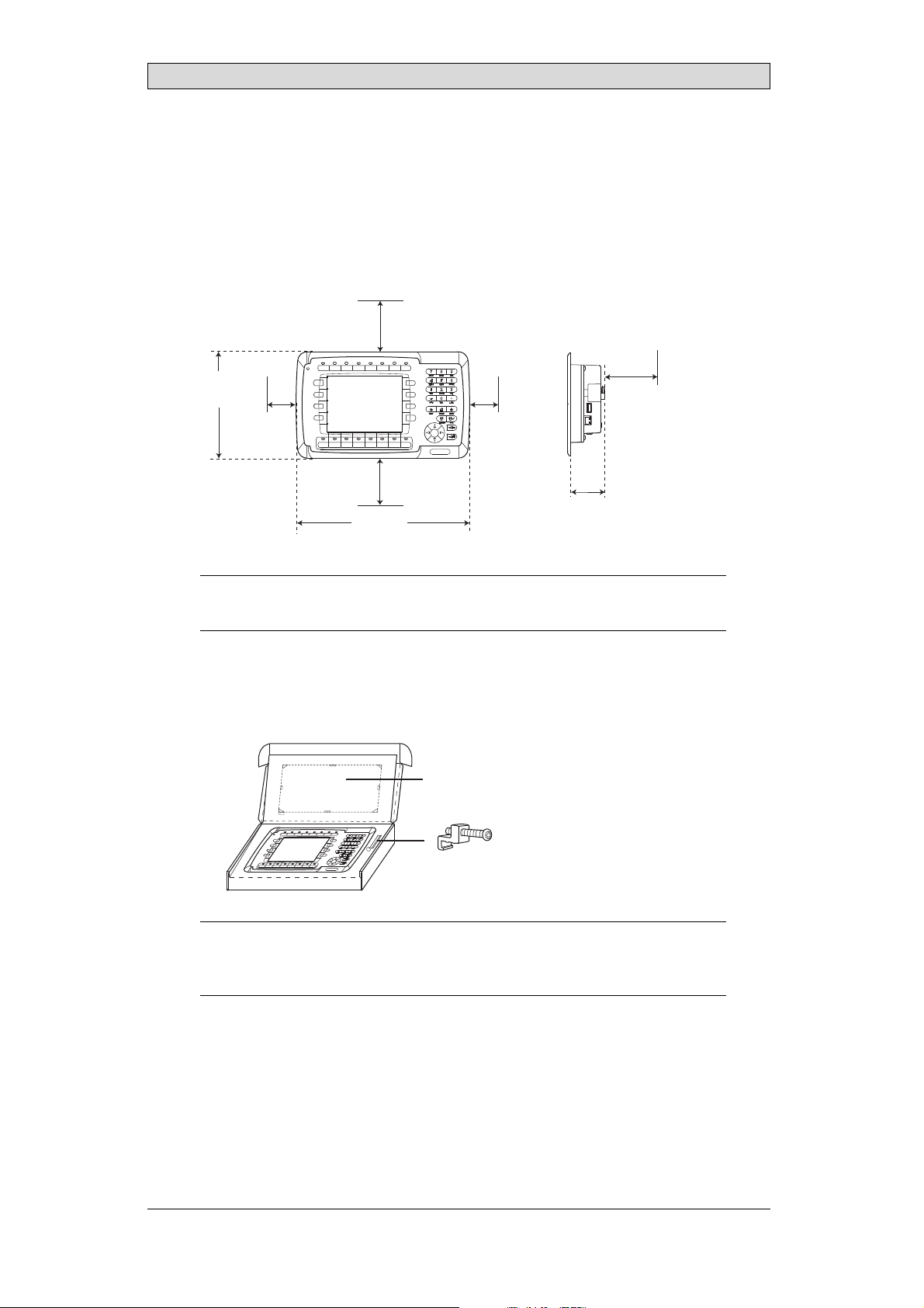
2.1 SpaceRequirements
• Installation plate thickness: 1.5 - 7.5 mm (0.06 - 0.3 inch)
• Space requirements when installing the operator panel:
100 mm
(4.0 inch)
Installation
168 mm
(6.61 inch)
50 mm
(2.0 inch)
100 mm
(4.0 inch)
275 mm
(10.83 inch)
Caution:
Theopeningsontheenclosureareforairconve
50 mm
(2.0 inch)
ction. Donotcovertheseopenings.
2.2 InstallationProcess
1.
Unpack and check the delivery . If dama
Panel cut out 240 x 130 mm
ge is found, notify the supplier.
100 mm
(4.0 inch)
57 mm
(2.24 inch)
(9.45 x 5.12 inch)
x 6
Note:
Placetheoperatorpanelonastablesurfaceduringinstallation.
Droppingitorlettingitfallmaycausedamage.
BeijerElectronics, MAEN997
6
Page 7
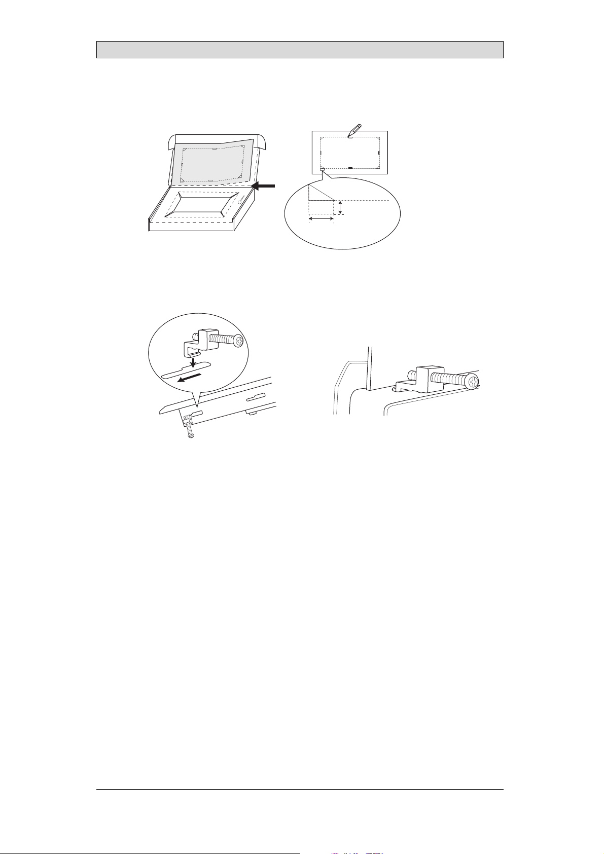
2.
Place the panel cut out where the operator panel is to be situated, draw along
the outer sides of the holes and cutaccording to the markings.
For text strip
7.0 mm
13.0 mm
(0.51 inch)
3.
Secure the operator panel in position, using all the fastening holes and the
(0.28 inch)
provided brackets and screws:
x 6
Installation
0.5 - 1.0 Nm
BeijerElectronics, MAEN997
7
Page 8
Installation
4.
Connect the cables in the specified order,according to the drawing and steps
below.
Caution:
• Ensurethattheoperatorpaneland thecontrollersystemhavethesameelectrical
grounding(referencevoltagelevel),otherwiseerrors incommunicationmay
occur.
• Theoperatorpanelmustbebroughttoambienttemperaturebeforeitisstarted
up. Ifcondensationforms,ensurethattheoperatorpanelis drybeforeconnecting
ittothepoweroutlet.
• Ensurethatthe voltageandpolarityofthepowersourceiscorrect.
• Useonlyshieldedcommunication cables.
• Separatehighvoltagecablesfromsignalandsupplycables.
B
Power
Controller
RS422/
RS485
RS232
24V DC
24V DC
C
D
A
Ethernet
– Connect cable A.
– Connect cable B, using an M5 screw and a grounding conductor (as short
as possible) with a cross-section of minimum 2.5 mm
– Connect cable C.
– Connect cable D.
5.
Carefully remove the laminated film over the operator p aneldisplay, to avoid
2
.
static electricity that could damage the panel.
BeijerElectronics, MAEN997
8
Page 9

2.2.1 ModeSwitches
All mode switches must be in OFF position during operator panel use.
Themodeswitchesshouldnotbetouchedunlessbyqualifiedpersonnel.
1 2 3 4
ON DIP
1 2 3 4
ON DIP
Installation
2.2.2 ConnectionstotheController
Forinformation about the cables to be used when connecting the operator panel to
the controller, please refer to the help file for the driver in question.
2.2.3 OtherConnectionsandPeripherals
Cables, peripheralequipment and accessories must be suitable for the application
and its environment. For further details or recommendations, please refer to the
supplier.
BeijerElectronics, MAEN997
9
Page 10

Technical Data
3TechnicalData
Parameter iX Panel K60
Frontpanel,WxHxD 275x168x6mm
Mountingdepth 57mm(157mmincludingclearance)
Frontpanelseal IP66
Rear panel seal IP 20
Keyboardmaterial Membraneswitch keyboardwith metaldomes. Over lay
filmofAutotexF157*withprintonreverseside. 1million
operations.
Reverse side
material
Weight 1.2 kg
Serialport
RS422/RS485
SerialportRS232C 9-pinD-subcontact,malewith standardlockingscrews4-40
Ethernet ShieldedRJ45
USB HosttypeA(USB1.1),m ax outputcurrent500mA
Realtimeclock ±20PPM+errorbecauseofambienttemperatureandsupply
Real timeclock
battery
Powerconsumption
atratedvoltage
Display TFT-LCD.320x240pixels,64Kcolors.
Activeareaof
display,W xH
Fuse InternalDCfuse,2 .0 AT,5x 20mm
Powersupply +24VDC(20- 30VDC).Powersupplyconnector.
Ambient
temperature
Storagetemperature -20°to+70°C
Relativehumidity 5-85% non-condensed
Approvalsand
certifications
Powder-coatedaluminum
25-pinD-subcontact,chassis-mountedfemalewith
standardlockingscrews4-40UNC
UNC
voltage. Totalmaximumerror: 1min/monthat25°C.
Temperature coefficient: -0.034±0.006ppm/°C
CR2450(ULandcUL:SanyoorPanasonic)
Minimumlifetime: 3years
Normal: 0.2A
Maximum: 0.4A
LEDbacklightlifetimeattheambienttemperatureof
+25°C:>20,000h.
115.2x86.4mm
CE:Thepowersupplym ust conformwiththerequirements
accordingtoIEC60950andIEC 61558-2-4.
ULandcUL:The powersupplymustconformwiththe
requirementsforclassIIpower supplies.
Verticalinstallation: 0 °to+50°C
Horizontalinstallation: 0°to+40°C
Informationisavailableonthewebsite
www.beijerelectronics.com
2
*SeesectionChemicalResistanceformoreinformation.
BeijerElectronics, MAEN997
10
Page 11

Chemical Resistance
4 ChemicalResistance
4.1 MetalCasing
The frame and casing material is powder-coated aluminum. T his powder paint
withstands exposure to the following chemicals without visible change:
Aceticacid10% Phosphoricacid4%
Citricacid10% Phosphoricacid10%
Diesel Seawater
Distilledwater Sodiumchloride2%
Edibleoil Sodiumchloride20%
Fueloil Sulphuricacid20%
Hydrogenperoxide3% Tapwater
The powder paint shows limited resistance to the f
ollowing chemicals at room
temperature:
Butanol Nitricacid3%
Hydrochloricacid5% Nitricacid10%
Isopropylalcohol Phosphoricacid43%
Na-hypochlorite10% Turpentine
Note:
Ifexposure toanyof theabovechemicalsis demanded,it isrecommended tofirsttest
thechemicalonan“invisible”spotofthemetalcasing.
Thepowderpaintshowslittleornoresistancetothefollowingchemicalsatroom
temperature:
Aceticacid,conc. Methyl-ethylketone Toluene
Acetone Nitricacid30% Trichlorethylene
Ammonia5% Phenol Xylene
Ammonia,conc. Sodiumhydroxide5% 97octanunleadedpetrol
Ethylacetate Sodiumhydroxide30% 98octanleaded petrol
BeijerElectronics, MAEN997
11
Page 12

Chemical Resistance
4.2 TouchScreenandOverlay
4.2.1 AutotexF157/207
Autotex F157 or F207 covers the overlay surrounding the touch screen.
SolventResistance
Autotex F157/F207 withstands exposure of more than 24 hours durationunder
DIN42115Part2tothefollowingchemicalswithoutvisiblechange:
Acetonitrile DieselDowney/Lenor
Ajax/Viminsolution EthanolPotassiumferricyanide
Alkalicarbonatesolution1Glycerine Potassiumhydroxide
Ammonia(<40%)
Aceticacid(<50%) Gumption
Arielpowderinsolution
1
Bleach
Castoroil Methanol Trichloroaceticacid
Causticsoda(<40%)
Cuttingoil Paraffinoil Windex
Cyclohexanol Persilpowderinsolution1Wisk
Diacetonealcohol Petroleumspirit
1
Extremely faint glossing of the texture was noted.
1
1
Glycol PureTurpentine
1
1
Hydrochloricacid(<36%) Sulfuricacid(<10%)
Linseedoil Tomato ketchup
Nitricacid(<10%) WhiteSpirit
1
Phosphoricacid(<30%)
(<30%)
SBP60/95
(<50%)
1
-
1
1
Autotex withstands DIN 42 115 Part 2 exposure of up to 1 hour duration to glacial
acetic acid without visible change.
Autotex is no
t resistant to high pressure steamat over 100 °C or the following
chemicals:
Concentratedmineralacids Benzylalcohol
Concentratedcausticsolution Methylenechloride
OutdoorUse
In common with all polyester based films Autotex F157/F207 is not suitable for
use in conditions of long term exposureto direct sunlight.
BeijerElectronics, MAEN997
12
Page 13

Chemical Resistance
4.2.2 TouchScreenSurface
Thetouchscreensurfaceonthepanelwithstandsexposuretothefollowing
solvents without visible change:
Solvents Time
Acetone 10minutes
Isopropanol 10 minutes
Toluene 5 hours
4.2.3 AutoflexEB
It is recommended to use the Autoflex EB touch display protection film , that can
be ordered from Beijer Electronics.
SolventResistance
Autoflex EB withstands exposure to the same chemicals as Autotex F157 or F207
according to section Autotex F157/207.
OutdoorUse
In common with all polyester based films Autotex EB is not suitable for use in
conditions of long term exposure to direct sunlight.
BeijerElectronics, MAEN997
13
Page 14

Operator PanelDrawings
5 OperatorPanelDrawings
5.1 CommunicationPorts
RS-232
RS-422/485
USB
RS-422
RS-485
Ethernet
BeijerElectronics, MAEN997
14
Page 15

5.2 iXPanelK60Outline
Operator PanelDrawings
BeijerElectronics, MAEN997
15
Page 16

5.3 iXPanelK60TextS trip
Text max 16,0x8,0
Text max 17,0x8,0
169
Operator PanelDrawings
4,5
18,45 18,9 18,9 18,9 18,9 18,9 18,45 10,3
9
BeijerElectronics, MAEN997
16
Page 17

Additional Installation Tips
6 AdditionalInstallationTips
When experiencingcommunication problems in for example noisy environments
or when operating close to temperature limits, the following recommendations
are to be no ticed.
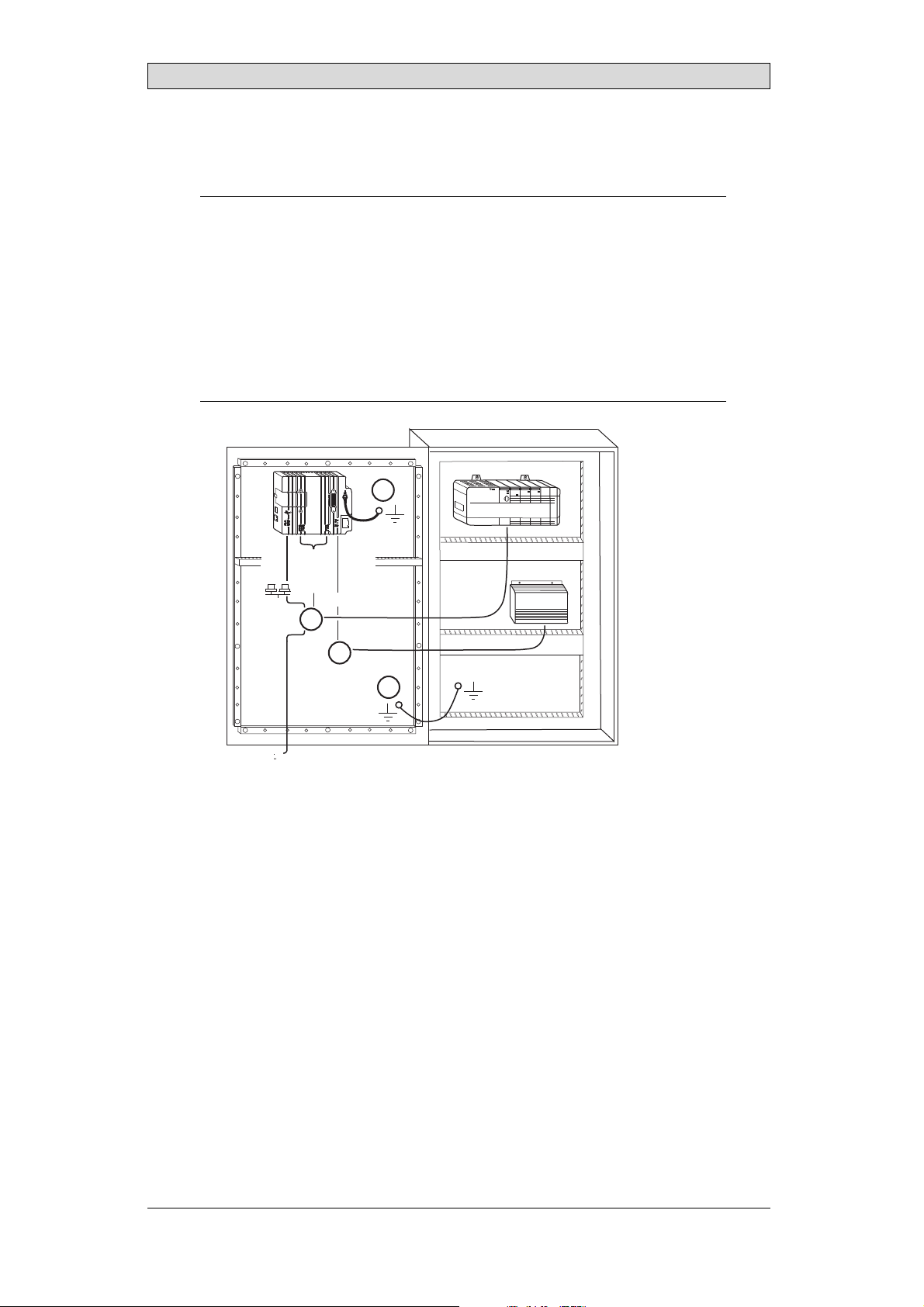
6.1 GroundingtheOperatorPanel
Door
Operator panel
1
Ferrite core
3
2
5
6
4
Mounting plate in the cabinet
Power supply
24 V DC
5350
The operator panel’s mountingclamps do not provide a secure grounding
connection between the panel and t he device cabinet, see 1 in drawing above.
1.
Connect a 2.5 mm
and the panel chassis, see 2 in drawi
2.
Connect a 6 or 4 mm
2
wire between the ope
rator panel’squick-connect plinth
ng above.
2
wire or grounding braid between the panel’schassis and
the closest grounding point on the door, see 3 in drawing above.
3.
Connect a strong but short grounding braid between the doorand the device
cabinet,see 4 in drawing above.
4.
Twist the cables onto the 24 V DC feed, see 5 in drawing above.
2 turns around the ferrite core provide 4 times the suppression of 1 turn.
3 turns around the ferrite core provide 9 times the suppression of 1 turn.
A ferritecore suppresses disturbances to the 24V feed, see 6 indrawing above.
Note:
Thegroundingwiresshouldbeshortandtheconductor shouldhavealarge area.
Along,thingroundingw ire hasaveryhighimpedance(resistance)athighfrequencies
andwillnotguidedisturbancestotheground.
Multi-wireconductorsarebetterthansinglewireconductorswiththesamearea.
Abraidedconductorwire withthe samearea isevenbetter. Thebestisashort,thick
groundingbraid.
BeijerElectronics, MAEN997
17
Page 18

Additional Installation Tips
6.2 EthernetConnectioninthePanel
Industrial Ethernet
RJ45
RJ45
RJ45
RJ45
Operator panel
RJ45
1
2
Operator panel
RJ45
Operator panel
RJ45
Operator panel
RJ45
5351
Shielded
0.1 uF
250 V
3
4
1-1
2-2
3-3
8-8
Short and
unshielded
5
In some industrial units for Ethernet, the RJ45 contact’s shield is co nnected to the
chassis via a capacitor, see 1 in drawing above.
The operator panel’s Ethernet shield is directly
connected to the chassis, see 2 in
drawing above.
1.
Check whether the other Ethernet unit hasits shield directly grounded or
grounded via a capacitor.
Note:
Inmanycases,connectingthe shieldedEthernetcablingtothe chassisatbothendsis
inappropriate. Humorgroundingloops canoccur. Unshieldedcablingmay evenresult
infewercommunicationerrors.
A good solution may be to use a shielded Ethernet cable, but to connect the shield
at one end only.
One option is to break the shield, see 3 in drawing above.
A more elegant method is to expand the shielded Ethernet cabling with a piece of
unshielded Ethernet cable, see 4 in drawing above.
You can ground the shield via an external 0.1 uF/250 V plastic capacitor, see 5 in
drawing above. Thiswill connect the HF transients to the ground.
BeijerElectronics, MAEN997
18
Page 19

Additional Installation Tips
6.3 ToAchieveBetterEMCProtection
• Initially, use the original cabling from Beijer Electronics primarily.
• Useshielded cables for RS232 communication.
• Usetwisted pair and shielded cabling for RS422 and RS485.
• Usethe cabling intended for the bus type; Ethernet, Profibus, CC-Link,
CAN, Device Net etc.
• Install and connect according to applicable specifications for the relevant bus
standard.
• Useshielded cabling for Ethernet, preferably with foil + braided shield.
• D-sub covers should be shielded, and the shield should be connected to the
cover 360 ° where the cable comes in.
• Connect the shield at both ends.
Shielded cable
0.1 uF/250 V
Ground plane 1 Ground plane 2
Ground plate Ground plate
Not same potential
in another building
5352
With longer distances, there is a risk that the ground potential may be different.
In that case, the shield should onlybe connected at one end. A good alternative
is to connect the other end of the shield to the ground via a 0.1 uF/250 V plastic
capacitor. Both ends are then connected to the ground in terms of HF, but only
connected to the ground at one end in terms of LF, thus avoiding the 50 Hz
grounding loops.
Metal cabinet Metal cabinet
Terminal or connector Terminal or connector
Cable clamp
in steel
Short distance
EMC cable gland Plastic cable gland
Shielded cable Shielded cable
1.
Usean EMC cable gland or regular plastic cable gland, remove the outer jacket
5353
and connect the shield to the installation plate with a 360 ° metal cable clamp.
2.
Place the 24 V DC and communicationscabling in one cable tr unk/cableduct
and 230/380 V AC in another. If the cables need to be crossed, cross them at
90 ° only. Avoid combining the cabling for stronger 24V DC outputs with
the communicatio n cabling.
Ferritecores that are snapped onto the shielded cabling may remove minor
disturbances. Large ferrite pieces that are snapped onto unshielded cabling and
where the wires go 2-4 times around the cores are approximately 5-25 times more
efficient.
BeijerElectronics, MAEN997
19
Page 20

Additional Installation Tips
6.4 AmbientTemperature
The maximum ambient temperature for the operator panel is provided in the
specifications. The ambient temperaturerefers to the temperature in the device
cabinet whichcools the panel’selectronics.
Top
50 °C inside
Operator
panel
30 °C outside
Middle
45 °C inside
Bottom
40 °C inside
Power
Power
Power
Axial fan
120 x 120 mm
Airflow
5354
Inmostcases,theambienttemperaturefortheoperatorpanelissignificantly
higher than the device cabinet’s ambient temperature.
If the cabinet is tall and there are a number of hea
temperature at the top of the cabinetwill be con
theoretical temperature increase that would
sensitivetoheat. Thelifespanofanelectro
° increase in temperature. A 15-20° tempera
t-generating devices, the
siderably higher than the
be expected. Allelectronics are
lytic capacitor is cut in half with an 8-10
ture increase results in a quarter of the
lifespan etc.
Rittal has a good program for estimating the anticipated average temperature in
the cabinet as well as a large program for controlling the temperature in the device
cabinet.
An enamel-coated steel cabinet has
a radiant heat value of 5.5 W/m
2
and degrees
C.
Installing a fan inside the cabinet will even out the temperature, while moving air
provides considerably better cooling than still air. A suitable fan is a 120 x 120 mm
axial fan, available in 24 V DC, 115 and 230 V AC.
Installthefansothatitsit
operator panel. If the fan i
ambient temperature will
s in the coo ler area and will blow cold air against the
s mounted at the top and sucks air upwards, the fan’s
be higher = shorter lifespan.
Agoodfanwithaball-bearingmountinghasanexpectedlifespanofatleast
40,000 hours (not a guaranteed lifespan) at 40 °C. This corresponds to at least 4
years of continuous u se. If a thermostat is installed, the fan only needs to come
on when needed.
Large graphic termi
lighting is off. Th
nals draw only one fifth of the current when the background
e loss effect drops from e.g. 25 W to only 5 W.
The operator panel’s loss effect = supply voltage x current. Virtually no power goes
to external users and no loss effects due to inputs.
BeijerElectronics, MAEN997
20
Page 21

6.5 Safety
Most of the operator panels are fed with 24 V DC.
Power supply
1
2
3
230 V AC to 24 V DC
Power supply
230 V AC to 24 V DC
Power supply
230 V AC to 24 V DC
230 V AC
+24 V
0 V
4
+24 V
0 V
4
Distance?
+24 V
0 V
4
Operator panel
Operator panel
Operator panel
Small controller with expansion unit
COM1
COM100
Ch0
Ch1
Ch100
Ch101
5355
Additional Installation Tips
Ifyouuseapowersupplythatmeetssafetystandardsandonlyfeedstheoperator
panel, there is no problem. See 1 in drawing above.
However,ifyouhavea24Vunitthatalsofeedsotherunits,thereisreasontobe
cautious, see 2 in drawing above. The operator panel does not have insulation that
meets safety requirements in the event of a potential short circuit between 230 V
AC and 24 V DC. It is assumed that the 24 V feed is secure, for example, SELV
according to EN 60950 (protection against electric shock) and UL 950.
Example:
Hereisanexamplethatexplainswhyasecure 24VDCfeedcanberuinedbymixing 24
Vrelaycontactswith230VACrelaycontactsinasmallercontroller. Checkthatthe
“clearancesandcreepagedistancesbetween24VDCand230 VACfulfillEN60950or UL
950”. Ifnot,inputa separate24Vunit intotheoperatorpanel.
If there is a substant
AC, it is OK to use the
ial distance between the relay contacts for 24 V DC and 230 V
same 24 V devices for all feeds. See 3 in drawing above.
Connect 0 V on the 24 V feed to the ground, see 4 in drawing above. This offers
three advantages:
• Safety is increa
connection or s
• Tr a n s i e n ts o n
• No risk that th
is not unusua
sed. The24Vfeedwillnotbeliveintheeventofafaulty
hortcircuitbetween0V(24V)and230Vphase.
the 24 V feed are connected to the ground.
e 24 V feed is at a high level in relationship to the ground. This
l since there is high static electricity.
BeijerElectronics, MAEN997
21
Page 22

6.6 GalvanicIsolation
r
Additional Installation Tips
+24 V DC
DC/DC
galvanic isolation
Filter
0 V
1.5 m
Internal electronic
VCC
0 V (GND)
RS232RS422/485
USB
USB
DC/AC
Ethernet
CFL
5356
The operator panel has galvanic isolation against the 24 V DC feed but no galvanic
isolation between the communication ports for RS232, RS422/485 and USB.
Only the Ethernet connection has galvanic isolation.
Operator panel Modular controller Printe
RS422 RS232 USB
**
* *
Not same ground potential
* = Internal 0 V (GND) connection
When a PC is connected to the panel, the panel’s internal 0 V (G
*
Power CPU COM COM2
***
*
PCPC
5357
ND) will be
connected to the protective ground via the PC.
A number of USB devices can have the shield connected togetherwith th e
protective ground. Here,the panel’s0 V (GND) is connectedto the protective
ground when, for example, a USB memory stick, keyboard or similar device is
plugged in.
If a number of units are connected that have a 0 V a
these are connected to various grounding poin
problems. Grounding currents go through com
of the controller,and i nternally in th
e operator panel, and can cause errors.
nd a ground connection, and
ts, there is a substantial risk of
munication cables, the rear plate
Use external units to improve comm unicationand achieve galvanic isolation.
Westermo has good industry-standard insulatorsthat are also insulated from the
24 V DC feed.
Note:
Itisveryimportanttomakesurethatthe24Vfeed intheexternalinsulationunit isnot
connectedtoone ofthecommunication outlets. Ifitdoesnothave100%insulation
againstthe24Vfeed,disturbancesandgroundingcurrentsfromthe0Vonthe 24V
sidewilldisruptcommunication.
Usingthistypeofunitsolvesoneproblembut createsalargerproblem! Asubstandard
installationmayworknow,butproblemsmayarisewhenother devicesareconnected.
BeijerElectronics, MAEN997
22
Page 23

Additional Installation Tips
6.7 CableandBusTerminationRS485
• Use shielded and twisted pair cable. The pair capacitance may not exceed 52.5
2
pF/m and area at least 0.25 mm
(AWG 24), if you want to use the maximum
transfer distance and maximum transfer speed.
• 0 V, the reference voltage for communication should be included in
the cabling. With two-way communication use two pairs; one pair for
communication and one pair for 0 V.
• The shield must be grounded at one end. The other end is usually grounded,
but with longer distances or when there is a difference in the ground potential,
theshieldshouldbeconnectedtothegroundvia0.1uF/250Vplastic
capacitor to prevent ground current in the braided shield. A number of
manufacturers recommend that the shield be grounded at each node. Various
manufacturers have different systems for bus termination. The RS485
standard does not describe how the “Fail Safe” function would be carried out,
justthatthesystemshouldbeabletohandletheerror.
Depending on the recipients’design, the bus wires may be on the same level or
require pull-up or pull-down to ensure that no faulty signals are detected when the
bus is in resting mode (all transmittersare disconnected).
Inside operator panel
+5 V
0 V
1 23
1 K
120 ohm 120 ohm
1 K
+5 V
(120 ohm)
14
1 K
2
15
6
19
1 K
7
8
0 V
0 V
4
55
17
50
Operator
panel
RS422
1 2 3 4 5 6 7 8
CAB8CAB8 Bus
2
15
3
16
17
4
14
+5 V
VCC
8
0 V
7
0 V
VCC
1 K
120 ohm
1 K
RS485
1
2
3
4
5
6
Shield
7
8
Bus termination
0 V
0 V
5358
Some (older) operator panels had pull-up and pull-down resistance except for
the actual bus termination at 120 ohm, similar to Westermo andProfibus. See 1
in drawing above.
Newer panels have another type of recipient, so-called built-in “Fail Safe”, where
simple bus termination resistance is sufficient. See2 in drawing above.
If other nodes on the RS485 network require pull-up and pull-down and the
operator panel is at one end of the loop, one of the following procedures can be
carried out:
• Connect two 1k/0.25 W resistors in the 25-pole D-sub contact. See 3 in
drawing above. Set jumper pins 6-19.
• UseCAB8. It offers the option of bus termination with pull-up/-down. It
isalsoeasytoconnectthebuscableviathescrewterminalblock. See4in
drawing above.
BeijerElectronics, MAEN997
23
Page 24

HEADOFFICE SUBSIDIARIES
SWEDEN GERMANY USA
BeijerElectronicsProductsAB Elektronik-SystemeLauerGmbH&Co. KG BeijerElectronicsInc.
Box426 Kelterstraße59 939N.PlumGroveRoad,Suite F
SE-20124Malmö,Sweden 72669Unterensingen,GERMANY Schaumburg,IL60173,USA
Tel: +46 40 35 8600 Tel: +49702296600 Tel: +1 847 6196068
Fax: +46 40 932301 Fax: +49 7022 9660 103 Fax: +1 847 619 6674
info@beijerelectronics.com info@lauer-hmi.com info.usa@beijerelectronics.com
TAIWAN CHINA
HitechElectronicsCorp. Beijer ElectronicsCo. Ltd
7&8F,No. 108 Min-QuanRoad Room201,BuildningB, No. 1618,
in-Tien,Taipei Shien, TAIWAN,R.O.C.231
Sh
Tel: +886-2-2218-3600 Tel: +862161450400
Fax: +886-2 -2218-9547 Fax: +862161450499
info.hmi@hitech-lcd.com.tw info@beijerelectronics.cn
shanRoad,Shanghai201103,CHINA
Yi
 Loading...