

Page 1

iXPanelK100
Service&MaintenanceManual
MAEN003,2010-05
English
Page 2

Service&Maintenancemanualfor iX PanelK100
Foreword
This manual contains detailedinformation about iX Panel K100, including
descriptions of various actions that can be carried out in orderto maintain or
update the operator panel h ardware and software.
The manual contains descriptions of basic maintenance and replacement of
common parts in iX Panel K100.
The manual assumes thatthe most recent versions of the system program
(firmware) and iXDeveloper are used.
The following other manuals are available for iX Panel K100:
iX PanelK100 installation manual (MAEN995x) for information regarding
installation.
iX Developer referencemanual (MAEN831x) for a descriptionof the
configuration tool.
iX Developer user’sguide (MAEN832x) for function-based descriptions.
Foreword
© Beijer ElectronicsAB, MAEN003, 2010-05
The information in this docu ment is subject tochangewithoutnoticeandisprovidedasavailableatthe
time of printing. Beijer ElectronicsAB reserves the rightto change any information without updating this
publication. Beijer Electronics AB assumes no responsibility for any errors that may appear in this document.
Read the entireinstallation manual prior to installing and usingthis equ ipment. Only qualified personnel
may install, operate or repair this equipment. Beijer ElectronicsAB is not responsible formodified, altered
or renovated equipment. Because the equipment hasa widerangeofapplications,usersmustacquirethe
appropriate know l edge to use the equipment properly in their specific applications. Personsresponsible
for the application and the equipment must themselves ensure that each application is in compliance with
all relevant requirements,standards and legislationinrespecttoconfigurationandsafety. Onlypartsand
accessories manufactured according to specifications set by Beijer ElectronicsAB maybe used.
BEIJER ELECTRONICSAB SHALL NOT BELIABLE TO ANYONE
FOR ANY DIRECT, INDIRECT, SPECIAL,INCIDENTAL OR
CONSEQUENTIAL DAMAGESRESULTING FROMTHE
INSTALLATION, USE OR REPAIR OF THIS EQUIPMENT, WHETHER
ARISING IN TORT, CONTRACT, OR OTHERWISE. BUYER'S SOLE
REMEDYSHALL BE THE REPAIR, REPLACEMENT, ORREFUND
OF PURCHASE PRICE, AND THE CHOICE OF THE APPLICABLE
REMEDYSHALLBEATTHESOLEDISCRETIONOFBEIJER
ELECTRONICSAB .
BeijerElectronics, MAEN003
Page 3

Contents
Contents
1 SafetyPrecautions ....................................................... 5
1.1 General ...........................................................
1.2 DuringInstallation ..............................................
1.3 DuringUse .......................................................
1.4 Service and Maintenance ........................................
1.5 Dismantling and Scrapping .....................................
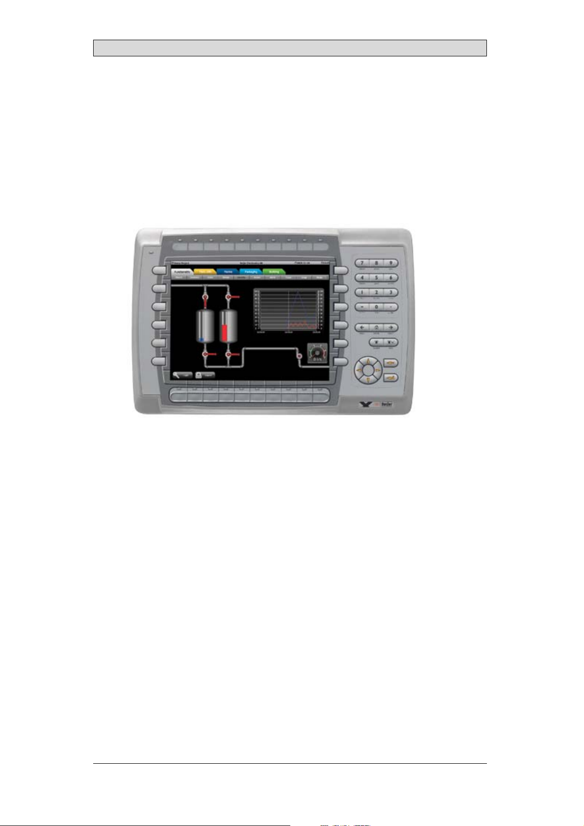
2 Introduction ............................................................. 7
2.1 iX PanelK100 ....................................................
2.2 Maintenance .....................................................
2.3 Service andRepairs ..............................................
2.4 Dismantling and Scrapping .....................................
2.5 Contact and Support ............................................
3 Installation ............................................................... 10
3.1 SpaceRequirements .............................................
3.2 InstallationProcess ..............................................
3.2.1 Connections to theController ..................................
3.2.2 OtherConnections and Peripherals ............. ................
4 Technical Data ........................................................... 14
5 Chemical Resistance .................................................... 15
5.1 MetalCasing .....................................................
5.2 Keyboard Material ...............................................
5.2.1 AutotexF157/207 ..................................... ..........
5.2.2 ScreenSurface .............. .....................................
5.2.3 AutoflexEB ..... .................................................
6 Hardware Tests .......................................................... 18
7 Additional Hardware ................................................... 19
7.1 Memory Card ....................................................
7.1.1 Installation .................. .....................................
7.1.2 SettingsiniX Developer .........................................
8 Hardware Replacement ................................................. 21
8.1 Mode Switches ...................................................
8.2 Cables .............................................................
8.3 Replacing the Rear Co
8.4 Replacing the Displa
8.4.1 Self-test of the Dis
ver ........................................
y/Display Cable . .........................
play ........................... ................
8.5 ReplacingtheCompleteFront ..................................
8.6 Replacing the Backlight . ........................................
8.7 AvailableSpare Parts for iX Panel K100 ........................
9 Service Menu ............................................................ 29
9.1 Service Menu in an Empty Panel ...............................
9.2 Service Menu in a Panelwith Project ...........................
9.3 Service MenuOptions ...........................................
9.3.1 IP Settings ...... ................................................ .
9.3.2 Date/Time ........................... ............................
9.3.3 Erase Project .................................................... .
10
10
13
13
15
16
16
17
17
19
19
20
21
22
23
24
25
26
27
28
29
29
29
29
29
29
5
5
6
6
6
7
8
8
8
9
BeijerElectronics, MAEN003
Page 4

Contents
9.3.4 Format MemoryCard ...... .....................................
30
10 HardwareSelf Test ...................................................... 31
11 Additional Installation Tips .. .......................................... 32
11.1 Grounding the Operator Panel .................................
11.2 Ethernet Connection in the Panel ..............................
11.3 To Achieve Better EMC Protection .............................
11.4 Ambient Temperature ...........................................
11.5 Safety .............................................................
11.6 Galvanic Isolation ................................................
11.7 Cable and Bus Termination RS485 .............................
32
33
34
35
36
37
38
12 FaultTracing ............................................................. 39
13 Software .................................................................. 41
13.1 General Information about Software ...........................
13.1.1 Software Products ............. ..................................
13.2 Update Software .................................................
13.2.1 iX Developer .................................. ...................
13.2.2 RemoteAccess Viewer ............... ............................
13.2.3 SystemProgram .......................................... .......
41
41
42
42
42
42
14 Environmental Aspects ................................................. 44
14.1 General Environmental Aspects ................................
14.2 Environmental Impact of theOperatorPanels .................
14.2.1 Mechanical Components ........................................
14.2.2 Electronics ........................... ............................
14.3 Recycling .........................................................
14.4 Environmental Impact Report ..................................
44
44
44
44
45
45
BeijerElectronics, MAEN003
Page 5

Safety Precautions
1SafetyPrecautions
Both the installer and the owner and/or operator of the operator panel must read
and understand this installation manual.
1.1 General
• Read the safety precautions carefully.
• Check the delivery for transportation damage. If damage is found, notify the
supplier as soon aspossible.
• Do not use the operator panel inan environment with high explosive hazards.
• The supplier is not responsible formodified, altered or reconstructed
equipment.
• Use only parts and accessories manufactured according tospecifications of
the supplier.
• Read the installationand operating instructions carefully before installing,
using or repairingthe operator panel.
• Neverallowfluids,metalfilingsorwiringdebristoenteranyopeningsinthe
operator panel. This may cause fire or electrical shock.
• Only qualified personnel may operate the operator panel.
• Storing the operator panel where the temperature is lower/higher than
recommended in this manual can cause the LCD display liquid to
congeal/become isotopic.
• The LCD display liq uid contains a powerfulirritant. In case of skincontact,
wash immediately with plentyof water. In case of eye contact, hold the eye
open,flushwithplentyofwaterandgetmedicalattention.
• Thefiguresinthismanualservesanillustrativepurpose. Becauseofthemany
variables associated with any p articular installation, the supplier cannot
assume responsibility for actual use based on the figures.
• The supplier neither guarantees that t he operator panel is suitable for your
particular application, nor assumes responsibility for your product design,
installation or operation.
1.2 DuringInstallation
• The operator panel is designed for stationary installation on a plane surface,
where thefollowing conditions arefulfilled:
– no high explosive risks
– no strong magnetic fields
– no direct sunlight
– no large, sudden temperature changes
• Install the productaccording to the accompanying installation instructions.
• Ground theproduct according to the accompanying installation instructions.
• Only qualified personnel may installthe operator panel.
• Separate the high voltage, signal and supply cables.
• Make surethat the voltage and polarity of the powersource is correct before
connecting the product to the power outlet.
• Peripheralequipment must be appropriate for the applicationand location.
BeijerElectronics, MAEN003
5
Page 6

Safety Precautions
1.3 DuringUse
• Keep the operator panel clean.
• Emergency stop and other safety functions may not be controlled from the
operator panel.
• Do not use too much force or sharp objects when touching the keys, touch
screenetc.
1.4 ServiceandMaintenance
• Only qualified personnel should carry out repairs.
• The agreed warrantyapplies.
• Before carrying out any cleaning or maintenance operations, disconnect the
equipment from theelectrical supply.
• Clean the display and surrounding front coverwith a soft cloth and mild
detergent.
• Replacing the battery incorrectly may result inexplosion. Only use batteries
recommended by the supplier.
1.5 DismantlingandScrapping
• The operator panel or parts thereof shall be recycled a cc
regulations.
• The followingcomponents contain substances t
to health and the environment: lithium batter
display.
hat might be hazardous
y, electrolytic capacitor and
ording to local
BeijerElectronics, MAEN003
6
Page 7
Introduction
2Introduction
This manual describes howto maintain the iX PanelK100.
The functions availablein iX Developer depend on which operator panel model is
used.
2.1 iXPanelK100
The followingdrawings are available for iX Panel K100:
• Outline drawing
• Panelcut-out
• Te x t s t ri p
BeijerElectronics, MAEN003
7
Page 8

Introduction
2.2 Maintenance
Carefully read the instructions before beginning maintenance on the operator
panel.
• Only qualified personnel shouldcarry out maintenance.
• The agreed warrantyand license agreements apply.
• Any damage to the operator panel caused by personnel invalidates the
warranty.
• Before carrying out any cleaning or maintenance operations, disconnect the
operator panel fromthe power supply.
• Clean the display and surrounding front coverwith a soft cloth and mild
detergent. Recommended cleaning fluids for the display are water and IPA
(Isopropyl Alcohol or Hexane).
• Replacing the battery incorrectly may result inexplosion. Only use batteries
recommended by the supplier.
• A 6-month warranty on all service parts is provided.
Maintenance personnel are permitted to carry out the followingaction s:
• Replacing the Rear Cover
• Replacing the Display/Display Cable
• Replacing the Complete Front
• Replacing the Backlight
2.3 ServiceandRepairs
• Only accredited companies arepermitted to perform service and repairs.
• Ifanon-accreditedcompanyconductsanykindofserviceorrepair,theagreed
warranty will be invalidated.
• If training is required,contact the supplier.
• All maintenance should be performed ina 15-30 °C temperature range.
• Any damage to the operator panel caused by personnel invalidates the
warranty.
• Contracts with customers supersedethe information in this document.
2.4 DismantlingandScrapping
• The operator panel, or parts thereof, should be recycledaccording to local
regulations.
• The followingcomponents contain substances that might behazardous to
health and the environment: lithium battery, electrolytic capacitor, display.
BeijerElectronics, MAEN003
8
Page 9

Introduction
2.5 ContactandSupport
If you want to report a fault or have a question aboutthe operator panels, please
contact your localsupplier or fill out the form on theweb site.
1.
Enter the web site www.beijerelectronics.com and select Support.
2.
Select Contact inthe menu. Makesure to provide informationabout type
number, serial number, environment and an installation description.
The form will be sentto the manufacturer’s help desk and theywill answer your
question or register your improvement/fault.
To ensure quick resolution, provide as many details as possible in yourreport.
Include the date andtime when the problem occurred, a description of what you
were trying to do, the detailed steps you took that led up to the problem, and
details about any error messages received.
BeijerElectronics, MAEN003
9
Page 10
3Installation
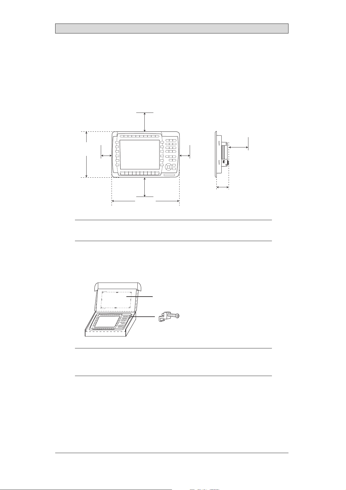
3.1 SpaceRequirements
• Installation plate thickness: 1.5 - 9.0 mm (0.06 - 0.35 inch)
• Space requirementswhen installing the operator panel:
100 mm
(4.0 inch)
252 mm
(9.92 inch)
50 mm
(2.0 inch)
100 mm
(4.0 inch)
382 mm
(15.04 inch)
50 mm
(2.0 inch)
58 mm
(2.28 inch)
Installation
100 mm
(4.0 inch)
Caution:
Theopenings ontheenclosureareforairconvection. Do notcovertheseopenings.
3.2 InstallationProcess
1.
Unpackand check the delivery. If damage is found, notify the supplier.
Panel cut out 343 x 208 mm
(13.5 x 8.18 inch)
x 14
Note:
Placethe operatorpanelonastablesurfaceduringinstallation.
Droppingitorlettingitfallmaycausedamage.
BeijerElectronics, MAEN003
10
Page 11
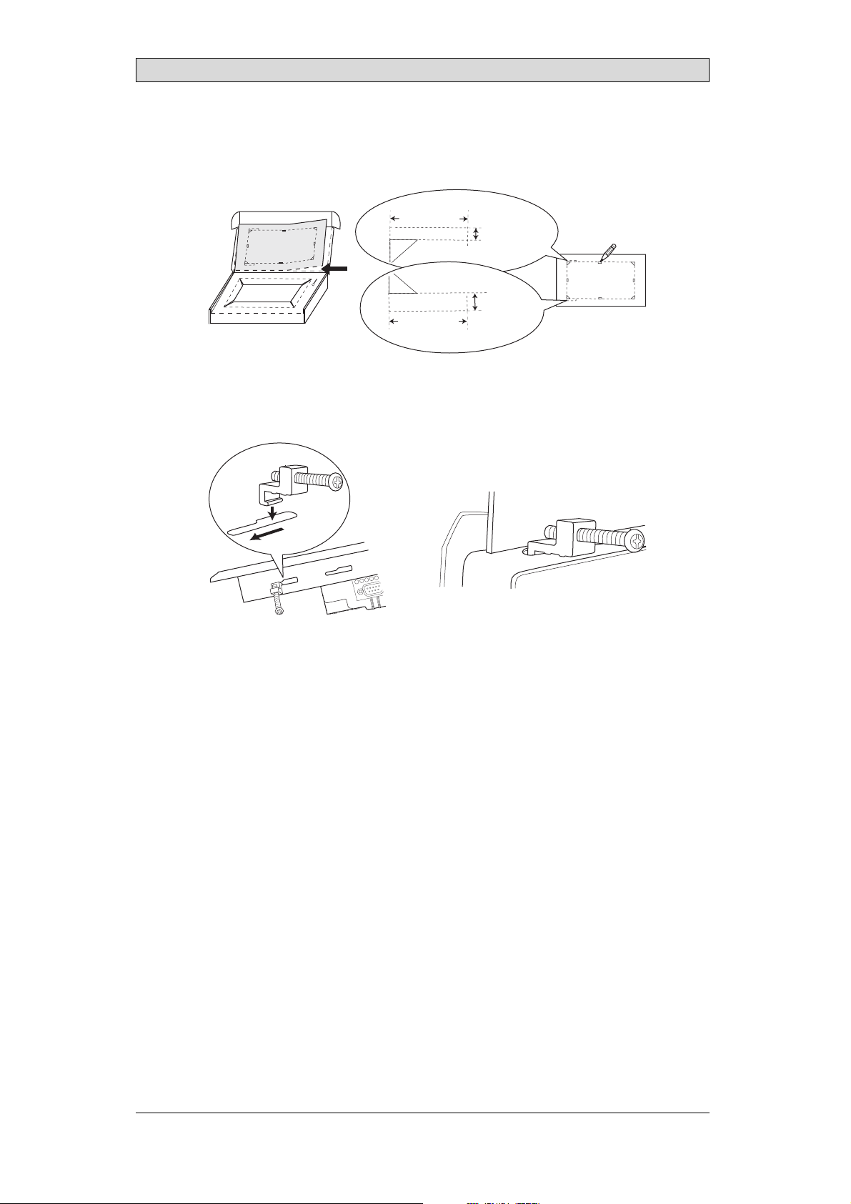
2.
Place thepanel cut out where the operatorpanel is to be situated,draw along
the outer sides of the holesand cut according to the markings.
For text strip
Installation
(1.38 inch)
35.0 mm
35.0 mm
(1.38 inch)
3.
Secure the operator panel in position, using all the fastening holes and the
3.5 mm
(0.14 inch)
6.5 mm
(0.26 inch)
provided brackets and screws:
x 14
0.5 - 1.0 Nm
BeijerElectronics, MAEN003
11
Page 12
Installation
4.
Connect the cables in the specified order, according to the drawing and steps
below.
Caution:
• Ensurethattheoperatorpaneland thecontrollersystemhavethesameelectrical
grounding(referencevoltagelevel),otherwiseerrors incommunicationmay
occur.
• Theoperatorpanelmustbebroughttoambienttemperaturebefore itisstarted
up. Ifcondensationforms,ensurethattheoperatorpanelisdrybeforeconnecting
itto thepoweroutlet.
• Ensurethatthevoltageandpolarity ofthepower sourceiscorrect.
• Useonly shieldedcommunicationcables.
• Separatehighvoltagecablesfromsignalandsupplycables.
Power
CF CARD
B
1
Controller
RS422/RS485
RS232
24V DC
24V DC
C
D
A
Ethernet
– Connect cable A.
– Connect cable B, using an M5 screw and agrounding conductor (as short
as possible) with across-section of minimum 2.5 mm
– Connect cable C.
– Connect cable D.
5.
Carefully removethe laminated film over the operator panel display, to avoid
2
.
static electricity thatcould damage the panel.
BeijerElectronics, MAEN003
12
Page 13

Installation
3.2.1 ConnectionstotheController
Forinformation about the cables to be usedwhen connecting the operator panel to
the controller,please refer to the help file for thedriver in question.
3.2.2 OtherConnectionsandPeripherals
Cables, peripheral equipment and accessories must be suitablefor the application
and its environment. Forfurther details or recommendations, please refer to the
supplier.
Caution:
Whenusingacompactflashcard, donotremovethecardwhenthebusyindicatoris
illuminated.
BeijerElectronics, MAEN003
13
Page 14
Technical Data
4TechnicalData
Parameter iXPanelK100
Frontpanel,WxHxD 382x252x6mm
Mountingdepth 58mm (158mmincludingclearance)
Frontpanel seal IP66
Rear panel seal IP 20
Keyboardmaterial Membraneswitchkeyboardwithmetaldomes. Overlay
filmof AutotexF157*withprintonreverseside. 1million
operations.
Reverseside
material
Weight 2.5 kg
Serialport
RS422/RS485
SerialportRS232C 9-pinD-subcontact,malewithstandardlockingscrews4-40
Ethernet ShieldedRJ45
USB HosttypeA(USB1.1),maxoutputcurrent500mA
CF-slot Compactflash,typeI andII
Realtimeclock ±20PPM +errorbecauseofambienttemperatureandsupply
Power consumption
atrated voltage
Display TFT-LCD.800x600pixels,64Kcolors.
Activeareaof
display,WxH
Fuse InternalDCfuse,3.15AT, 5x20mm
Powersupply +24V DC(20-30VDC).Powersupplyconnector.
Ambient
temperature
Storagetemperature -20° to+70°C
Relativehumidity 5- 85%non-condensed
Approvalsand
certifications
Powder-coatedaluminum
25-pinD-sub contact,chassis-mountedfemalewith
standardlo cking screws4-40UNC
UNC
DevicetypeB(USB1.1)
voltage. Totalmaximumerror: 1min/monthat25°C.
Temperature coefficient: -0.034±0.006ppm/°C
Rechargeablebattery.
Normal: 0.5A
Maximum: 1.0A
CCFLbacklight lifetimeat theambienttemperatureof
+25°C:>50,000h.
211.2x 158.4mm
CE:The powersupplymustconformwiththerequirements
accordingtoIEC60950 andIEC 61558-2-4.
ULand cUL:Thepowersupplymust conformwiththe
requirementsforclassIIpowersupplies.
Verticalinstallation: 0°to+50°C
Horizontalinstallation: 0°to +40°C
Informationisavailableon thewebsite
www.beijerelectronics.com
2
*SeesectionChemicalResistanceformoreinformation.
BeijerElectronics, MAEN003
14
Page 15

Chemical Resistance
5 ChemicalResistance
5.1 MetalCasing
The frame and casing material is powder-coated aluminum. This powder paint
withstands exposure tothe following chemicals without visible change:
Aceticacid 10% Phosphoricacid4%
Citricacid10% Phosphoricacid10%
Diesel Seawater
Distilledw ater Sodiumchloride2%
Edibleoil Sodiumchloride20%
Fueloil Sulphuricacid 20%
Hydrogenperoxide3% Tapwater
The powder paint shows limited resistance to the f
ollowing chemicals at room
temperature:
Butanol Nitricacid3%
Hydrochloricacid5% Nitricacid10%
Isopropylalcohol Phosphoricacid43%
Na-hypochlorite10% Turpentine
Note:
Ifexposureto anyofthe abovechemicalsisdemanded,itis recommended tofirsttest
thechemical onan“invisible”spotofthemetalcasing.
Thepowderpaintshowslittleornoresistancetothefollowingchemicalsatroom
temperature:
Aceticacid, conc. Methyl-ethylketone Toluene
Acetone Nitricacid 30% Trichlorethylene
Ammonia5% Phenol Xylene
Ammonia,conc. Sodiumhydroxide5% 97octanunleadedpetrol
Ethylacetate Sodiumhydroxide30% 98octanle ad edpetrol
BeijerElectronics, MAEN003
15
Page 16

Chemical Resistance
5.2 KeyboardMaterial
5.2.1 AutotexF157/207
Autotex F157 or F207covers the overlay surrounding the screen.
SolventResistance
Autotex F157/F207 withstands exposureof more than 24 hours duration under
DIN42115Part2tothefollowingchemicalswithoutvisiblechange:
Acetonitrile DieselDowney/Lenor
Ajax/ Vimin solution EthanolPotassiumferricyanide
Alkalicarbonatesolution1Glycerine Potassiumhydroxide
Ammonia(<40%)
Aceticacid (<50%) Gumption
Arielpowderinsolution
1
Bleach
Castoroil Methanol Trichloroaceticacid
Causticsoda(<40%)
Cuttingoil Paraffinoil Windex
Cyclohexanol Persilpowderin solution1Wisk
Diacetonealcohol Petroleumspirit
1
Extremely faint glossingof the texture was noted.
1
1
Glycol PureTurpentine
1
1
Hydrochloricacid(<36%) Sulfuricacid(<10%)
Linseedoil Tomatoketchup
Nitricacid (<10%) WhiteSpirit
1
Phosphoricacid(<30%)
(<30%)
SBP60/95
(<50%)
1
-
1
1
Autotex withstands DIN 42 115 Part 2 exposure of up to 1 hour duration to glacial
acetic acid without visible change.
Autotex is no
t resistant to high pressure steam at over 100 °C or the following
chemicals:
Concentratedmineralacids Benzylalcohol
Concentratedcaustic solution Methylenechloride
OutdoorUse
In common withall polyester based films Autotex F157/F207is not suitable for
use in conditions oflong term exposure to direct sunlight.
BeijerElectronics, MAEN003
16
Page 17

Chemical Resistance
5.2.2 ScreenSurface
The screen surface on the panel withstands exposure to the following solvents
without visible change:
Solvents Time
Acetone 10minutes
Isopropanol 10minutes
Toluene 5 hours
5.2.3 AutoflexEB
It isrecommended to use the AutoflexEB key protection sheet, that can be ordered
from Beijer Electronics.
SolventResistance
Autoflex EB w ithstands exposure to the same chemicals as AutotexF157 or F207
according to section AutotexF157/207.
OutdoorUse
In common withall polyester based films Autotex EB is not suitable for use in
conditions of long termexposure to direct sunlight.
BeijerElectronics, MAEN003
17
Page 18

Hardware T ests
6 HardwareTests
Before the operatorpanels are approved for market introduction, they are tested
by independent authorities. The iX Panelsare examined by several authorities
before being approvedfor market introduction. All operator panelsare designed
to fulfill standards suchas CE. The quality policy and environmental policy place
demands on all suppliers and subcontractors.
The manufacturer performs extensive hardware testing before an operator panel
is approved. Some tests are performed by external testing companies, such as
the SwedishNational Testing and Research Institute. All operator panels are
submitted to testing before leaving the manufacturer.
BeijerElectronics, MAEN003
18
Page 19

Additional Hardware
7 AdditionalHardware
7.1 MemoryCard
An internalCompact Flash memory cardcan be used iniX Panel K100for
expansion of theproject memory.
Note:
WhenusinganinternalCompactFlashmemorycard,noexternalCompactFlash
memorycardcanbeused. AnexternalUSBFlashdrivecanbeusedforthesame
functionsasanexternalCompactFlashcard.
Compact Flash cards of type I and II aresupported.
Compact Flash cards of the following brands and models are recommended:
SiliconSystemsSiliconDrive
SanDiskIndustrialGrade
Cactus203-,302-and 303–series
Other Compact Flashcards may be approvedas accessories for the iX Panelseven
if they are not present in the abovelist, due to product changes and upcoming
brands.
7.1.1 Installation
Performthe following steps to install an internalCompact Flash card in the
operator panel:
1.
Turn off the powerto the panel.
Note:
MakesuretouseadequateESDprotection.
2.
Followthe instructions in the Replacing the Rear Cover section to remove the
rear cover.
3.
Flipthe back cover;the CPU board is mounted inside theback cover.
4.
Insert the Compact Flash memory card in its slot on theCPU board.
memory card slot
BeijerElectronics, MAEN003
19
Page 20

Additional Hardware
5.
Re-attach the back cover to the operator panel.
6.
Turn on the powerto the operator panel.
When the operator panelstarts up,you will be asked if you like to move the
files to the internal card;select YES to this question.
7.1.2 SettingsiniXDeveloper
The size of the internal memory card must be enteredin iX Developer.
1.
Click on Settings onthe Project group of the Project ribbon tab.
2.
Select the Display/Panel properties.
The sizeof the internal memory cardis stated under Memory Card.
BeijerElectronics, MAEN003
20
Page 21

Hardware Replacement
8 HardwareReplacement
This section contains instr uctions on how to replace operator panelhardware.
Only components included in the latest bill ofmaterial and spareparts list are
allowed. See Available Spare Parts for iX Panel K100.
8.1 ModeSwitches
The iX Panel K100 hasfour mode switches (DIP switches) located on the rear side
of the operator panel.
1 2 3 4
MODE
ON DIP
10/100
EXPANSION
RS232
COM 2
24V DC
1
1 2 3 4
MODE
ON DIP
CF CARD
BUSY
COM 1
RS422
RS485
Warning:
Themodes belowaretobeusedwithcaution.
Themodeswitcheshavethefollowingfunctions: 1=ON,0=OFF
Each letter in “MODE” has a corresponding mode switch.
MODE Description
0000 “Runmode”-bootsCE,normaloperation.
0010 SystemRestore,resetsthefilesystemandregistry,
reinstallsthe systemprogram(OPsys_bxxx.CAB).Restores
theoperatorpanel tofactorysettings.
Warning! Informationcaneasilyaccidentlybelost.
0100 ImageLoad mode(Sysload)allowsupgradingof the
firmwareintheoperatorpanel.
Note: Allfilesincludingthefilesystemintheoperator
panelwillbe deletedwhenupgradingwithImageLoader.
1000 ServiceMenumode,t he servicemenuforthesystem
programisshown. AllowstheusertosetIPconfiguration,
erasethe project,calibratethetouchscreenetc. See
sectionService Menufor details.
BeijerElectronics, MAEN003
21
Page 22

Hardware Replacement
MODE Description
1100 Notused (runmode).
1110 Self-test.
xxx1 Hardreset(forcesthe systemtoreset).
To change mode switches, follow the steps below:
1.
Disconnect power from the operator panel.
2.
Set the mode switches using aballpoint pen.
3.
Reconnect powerto the operator panel.
8.2 Cables
Mostoftheoperatorpanelsusethesametypeofflexcableconnectors.
connector flanges
Flex cable connector
To release the flex cablesfrom the connector, gently push th e two flanges on the
cable connector towards the flex cable.
Note:
Theconnectorsmustbeunlockedon bothsidesbeforeremoving thecable,otherwise
theflexcablemaybedamaged.
BeijerElectronics, MAEN003
22
Page 23

Hardware Replacement
8.3 ReplacingtheRearCover
The followingis needed:
• Anewrearcover,seeAvailable SpareParts for iX Panel K100
• AtorxT10screwdriver
Note:
MakesuretouseadequateESDprotection.
Follow the stepsbelow to replacethe rear cover:
1.
Poweroff the operator panel.
2.
Remove the rear cover of the operator panel by loosening the 4 torx screws.
4 x torx screws
3.
Re-assemble withthe new rear cover inreverse order.
BeijerElectronics, MAEN003
23
Page 24

Hardware Replacement
8.4 ReplacingtheDisplay/Display Cable
The followingis needed:
• A new display/display cable, seeAvailable Spare Parts for iX Panel K100
• AtorxT10screwdriver
Note:
MakesuretouseadequateESDprotection.
Followthe steps belowto replace the display/display cable:
1.
Poweroff the operator panel.
2.
Followthe instructions under Replacing the Rear Cover to removethe rear
cover.
3.
Disconnect the two flex cables the flex cable and the LED cable fromthe
power cardand remove the two plastic nuts that hold the power card in place.
plastic nut
flex cables
plastic nut
4.
Lift the powercard and gently remove
cablefromtherearsideofthepower
5.
Remove the mounting plate (9 torx screws). Gently lift the mounting plate
the backlight cables andthe display
card.
with the display and powercard.
9 x torx screws
BeijerElectronics, MAEN003
24
Page 25

Hardware Replacement
6.
Flip the mountingplate and unscrew the 4 torx screws.
4 x torx screws
7.
Make sure the display cable is attached to the new display beforereattaching
the mounting plate.
8.
Re-assemble the panel in reverse order.
8.4.1 Self-testoftheDisplay
To perform a self-test of the display, follow the steps below:
1.
Start the operator panel in a self-test mode (see table inthe
Mode Switches section).
2.
Go to the display test. Verify that the display works.
3.
If the screendoes not work, try fault tracing, see the Fault T
racing section.
BeijerElectronics, MAEN003
25
Page 26

Hardware Replacement
8.5 ReplacingtheCompleteFront
The followingis needed:
• Anewfront,seeAvailableSpare Parts for iX Panel K100
• AtorxT10screwdriver
Note:
MakesuretouseadequateESDprotection.
Followthe steps belowto replace the complete frontof the iX PanelK100:
1.
Poweroff the operator panel.
2.
Followthe steps 1-3 and 5 in the Replacing the Display/Display Cable instructions, but in step 3,only disconnect the flex cable.
3.
Attach the new front.
4.
Re-assemble the unit.
BeijerElectronics, MAEN003
26
Page 27

Hardware Replacement
8.6 ReplacingtheBacklight
Note:
Alllamps inthedisplaymustbereplacedatthesametime.
The followingis needed:
• A new backlight, see Available Spare Parts for iX Panel K100
• AtorxT10screwdriver
Note:
MakesuretouseadequateESDprotection.
Followthe steps below to replace the battery of the iX Panel K100:
1.
First,follow the steps 1–5 in section Replacing the Rear Cover.
2.
Gently move the backlight diagonally indirection from the display center to
release the snap-in closurethat keeps the backlight in place.
3.
Remove the backlight from the display.
backlight
backlight snap lock
4.
Insert the new backlight. Be careful not topull the cables of the new backlight
when inserting it, since pulling the cables will damage the backlight.
5.
Re-assemble the complete operator panel.
connectors
BeijerElectronics, MAEN003
27
Page 28

Hardware Replacement
8.7 AvailableSparePartsforiXPanel K100
Ordernumber Description
601009277 COMPLETEFRONT
Includingfrontcover, glass,keyboard,gasketsandlabels
601009027 DISPLAY
Includingframeandcable
601009050 BACKLIGHT
601009028 DISPLAYCABLE
321099040 POWERCONNECTOR
601009011 REARCOVER
601009003 CFCOVER
601009001 MOUNTINGBRACKETS
601009056 KEYPROTECTIONSHEET
601009269 FRONTLABEL
601009137 COMPLETEBOX
601009008 TESTPLUGETHERNET
EthernetRJ45testconnector
601009006 TESTPLUGRS232
RS232test connector
601009007 TESTPLUGRS422/485
RS422/485testconnector
601009004 TESTPLUGUSBH-D
USBH ost andDevicetestconnector
601009069 TESTPLUGUSBH
USBHosttestconnector
BeijerElectronics, MAEN003
28
Page 29

Service Menu
9ServiceMenu
The service menu for the operator panel can be accessed before a project is
downloaded, or by setting the mode switches in mode 1000. The location of the
mode switches is describedin the Mode Switches section.
9.1 ServiceMenuinanEmptyPanel
When no project is loaded in the panel memory,the panel will boot, displaying the
Welcome screen. Press anywhere onthe panel display to enter the service menu.
9.2 ServiceMenuinaPanelwith Project
When a project isloaded in the panel memory,the panel will automatically start to
execute theproject. To display the service menu atboot-up:
1.
Disconnect the powersupply from the panel.
2.
Set the mode switches in mode 1000 (Service Menu mode).
3.
Connect the powersupply.
4.
Make desiredsettings in the service menu.
5.
Disconnect the powersupply from the panel.
6.
Set themode switches in mode0000 (Run mode).
7.
Reconnect the power supply.
9.3 ServiceMenuOptions
The followingoptions are available in the Service Menu:
9.3.1 IPSettings
Select to obtain an IP address automa
The IP address c an also be set during
9.3.2 Date/Time
Use the Date/Time Settings dialog to set the time zone, dateand time for the
panel.
9.3.3 EraseProject
The erase functionwill detect if the projectis located in the panel memory or o n a
memory card. Pressing Erase Project will completely removethe project and all its
components from the panelmem ory/the memory card.
tically via DHCP, or specify an IP address.
project transfer.
BeijerElectronics, MAEN003
29
Page 30

Service Menu
9.3.4 FormatMemoryCard
The format memory cardfunction will detect if external andinternal memory
cards. Select which card to format and, in some cases, formattingalternatives.
BeijerElectronics, MAEN003
30
Page 31

Hardware Self Test
10 HardwareSelfTest
The self-test programcan be used to test aspectsof operator panel functionality
and thecommunication ports. To run thetest you will need:
• Test plugs; see Tes t p l ug dr aw i ng .
• 24 V DC, min. 3 A.
Followthe steps below to run the self-test program on the operator panel:
1.
Poweroff the operator panel.
2.
Go to the self-test. Set the mode switches to the self-test positions, see thetable
in the Mode Switches section.
3.
Power on the operator paneland follow the instructions at the bottom of the
display.
4.
When using thetest plugs, make sure all LEDs onthe 9-pin and 25-pin
D-subs areon.
5.
When the self-testis finished, power off the operatorpanel and set all mode
switches tothe OFF position.
If an error occurs during the self-test, try to fault trace. See Fault T raci
ng.
BeijerElectronics, MAEN003
31
Page 32

Additional InstallationTips
11 AdditionalInstallationTips
When experiencing communication problems in for example noisy environments
or when operating close to temperature limits, the following recommendations
are to benoticed.
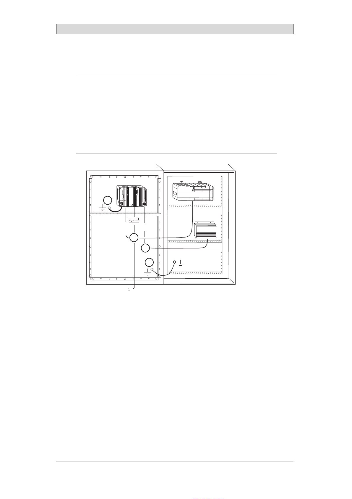
11.1 GroundingtheOperatorPanel
Door
Operator panel
1
Ferrite core
3
2
5
6
4
Mounting plate in the cabinet
Power supply
24 V DC
5350
The operator panel’s mounting clamps do not provide a secure grounding
connection between the panel and the device cabinet, see 1 in drawing above.
1.
Connect a 2.5 mm
and the panel chassis, see2 in drawi
2.
Connect a 6 or 4 mm
2
wire betweenthe ope
rator panel’s quick-connect plinth
ng above.
2
wire or grounding braid between the panel’s chassis and
the closest grounding point on the door, see 3 in drawing above.
3.
Connect a strong butshort grounding braid between the door and the device
cabinet,see 4 in drawing above.
4.
Twist the cables ontothe 24 V DC feed, see 5in drawing above.
2 turns aroundthe ferrite core provide 4 timesthe suppression of 1 turn.
3 turns aroundthe ferrite core provide 9 timesthe suppression of 1 turn.
A ferrite core suppresses disturbances to the 24 V feed, see 6 in drawing above.
Note:
Thegroundingwiresshouldbeshortandtheconductor shouldhavealargearea.
Along, thingroundingwirehasaveryhigh impedance(resistance)athigh frequencies
andwill notguidedisturbancestotheground.
Multi-wireconductors arebetterthansinglewireconductorswiththesamearea.
Abraidedconductorwirewiththe sameareaisevenbetter. Thebestisashort,thick
groundingbraid.
BeijerElectronics, MAEN003
32
Page 33

Additional InstallationTips
11.2 EthernetConnectioninthePanel
Industrial Ethernet
RJ45
RJ45
RJ45
RJ45
Operator panel
RJ45
1
2
Operator panel
RJ45
Operator panel
RJ45
Operator panel
RJ45
5351
Shielded
0.1 uF
250 V
3
4
1-1
2-2
3-3
8-8
Short and
unshielded
5
In some industrial units for Ethernet,the RJ45 contact’s shield is connected to the
chassis via acapacitor, see 1in drawing above.
The operator panel’s Ethernet shield isdirectly
connected to the chassis, see 2 in
drawing above.
1.
Check whether the other Ethernetunit has its shield directly grounded or
grounded via a capacitor.
Note:
Inmanycases,connectingtheshieldedEthernetcablingtothechassisatboth endsis
inappropriate. Humor groundingloopscanoccur. Unshieldedcablingmayevenresult
infewercommunicationerrors.
A good solution may beto use a shielded Ethernet cable, but to connect the shield
at one end only.
One option is to break the shield, see 3 in drawing above.
A more elegant method is to expand the shielded Ethernet cabling with a piece of
unshielded Ethernetcable, see 4 in drawing above.
You can ground the shield via an external 0.1uF/250 V plastic capacitor,see 5 in
drawing above. This will connect the HF transients to the ground.
BeijerElectronics, MAEN003
33
Page 34

Additional InstallationTips
11.3 ToAchieveBetterEMCProtection
• Initially,use the original cabling from BeijerElectronics primarily.
• Use shielded cables for RS232communication.
• Use twisted pair and shielded cabling for R S422 and RS485.
• Use the cabling intended for the bus type; Ethernet,Profibus, CC-Link,
CAN, Device Netetc.
• Install and connect according to applicable specifications forthe relevant bus
standard.
• Use shielded cabling for Ethernet,preferably with foil +braided shield.
• D-sub covers should be shielded, and the shield should beconnected to the
cover 360 ° where the cable comes in.
• Connect the shield at both ends.
Shielded cable
0.1 uF/250 V
Ground plane 1 Ground plane 2
Ground plate Ground plate
Not same potential
in another building
5352
With longer distances, there isa risk that the ground potential may be different.
In that case,the shield should only be connected at one end. A good alternative
is to connect the other end of the shield to the ground via a 0.1 uF/250 V plastic
capacitor. Both endsare then connected to the ground interms of HF, but only
connected to the groundat one end in terms of LF, thus avoiding the 50 Hz
grounding loops.
Metal cabinet Metal cabinet
Terminal or connector Terminal or connector
Cable clamp
in steel
Short distance
EMC cable gland Plastic cable gland
Shielded cable Shielded cable
1.
Usean EMC cable gland or regular plastic cable gland, removethe outer jacket
5353
and connect theshield to the installation plate with a 360 °metal cable clamp.
2.
Place the 24 V DC and communications cabling in one cable trunk/cable duct
and 230/380 V ACin another. If the cables need to be crossed, cross them at
90 ° only. Avoidcombining the cabling for stronger 24 V DC outputs with
the communication cabling.
Ferritecores that are snappedonto the shielded cabling may remove minor
disturbances. Large ferrite pieces that aresnapped onto unshielded cablingand
where the wiresgo 2-4 times around the cores are approximately 5-25 times more
efficient.
BeijerElectronics, MAEN003
34
Page 35

Additional InstallationTips
11.4 AmbientTemperature
The maximum ambient temperaturefor the operator panel is provided in the
specifications. The ambient temperature refers to the temperature in the device
cabinet which cools the panel’s electronics.
Top
50 °C inside
Operator
panel
30 °C outside
Middle
45 °C inside
Bottom
40 °C inside
Power
Power
Power
Axial fan
120 x 120 mm
Airflow
5354
Inmostcases,theambienttemperaturefortheoperatorpanelissignificantly
higher than thedevice cabinet’s ambient temperature.
If the cabinetis tall and there are a number of hea
temperature at thetop of the cabinet will be con
theoretical temperature increasethat would
sensitivetoheat. Thelifespanofanelectro
° increase in temperature. A 15-20 ° tempera
t-generating devices,the
siderably higher than the
be expected. All electronics are
lytic capacitor is cut in half with an 8-10
ture increase results in a quarter of the
lifespan etc.
Rittal has a goodprogram for estimating the anticipated average temperaturein
the cabinet as wellas a large program for controlling the temperaturein the device
cabinet.
An enamel-coated steelcabinet has
a radiant heat valueof 5.5 W/m
2
and degrees
C.
Installing a fan inside the cabinet will even out the temperature,while moving air
provides considerably better cooling than still air. A suitable fan is a 120 x 120 mm
axial fan, availablein 24 V DC, 115 and 230 V AC.
Installthefansothatitsit
operator panel. If the fan i
ambient temperaturewill
s in thecooler area and will blow coldair against the
s mounted at thetop and sucks air upwards, the fan’s
be higher = shorter lifespan.
Agoodfanwithaball-bearingmountinghasanexpectedlifespanofatleast
40,000 hours (not a guaranteed lifespan) at 40 °C. Thiscorresponds to at least 4
years of continuous use. If a thermostat is installed, the fanonly needs to come
on when needed.
Large graphic termi
lighting is off. Th
nals draw only one fifth of the currentwhen the background
e loss effect drops from e.g. 25 W to only5 W.
The operator panel’s loss effect = supply voltage x current. Virtually no power goes
to external users andno loss effects due to inputs.
BeijerElectronics, MAEN003
35
Page 36

11.5 Safety
Most of the operator panels are fed with 24 V DC.
Power supply
1
2
3
230 V AC to 24 V DC
Power supply
230 V AC to 24 V DC
Power supply
230 V AC to 24 V DC
230 V AC
+24 V
0 V
4
+24 V
0 V
4
Distance?
+24 V
0 V
4
Operator panel
Operator panel
Operator panel
Small controller with expansion unit
COM1
COM100
Ch0
Ch1
Ch100
Ch101
5355
Additional InstallationTips
Ifyouuseapowersupplythatmeetssafetystandardsandonlyfeedstheoperator
panel, there isno problem. See1 in drawing above.
However,ifyouhavea24Vunitthatalsofeedsotherunits,thereisreasontobe
cautious, see 2 in drawing above. The operator panel does not have insulation that
meets safety requirementsin the event of apotential short circuit between 230 V
AC and 24 V DC. It is assumed that the 24 V feed is secure, for example, SELV
according to E N 60950 (protection against electric shock) and UL 950.
Example:
Hereis anexamplethatexplainswhyasecure 24VDCfeedcanber uined bymixing24
Vrelaycontactswith230VACrelaycontactsin asmallercontroller. Checkthatthe
“clearancesand creepagedistancesbetween24VDCand230V ACfulfillEN60950orUL
950”. Ifnot, inputaseparate24V unitintotheoperatorpanel.
If there is a substant
AC, it is OK to use the
ial distance between therelay contacts for 24 V DC and 230 V
same 24 V devicesfor all feeds. See 3 in drawing above.
Connect 0 V on the 24 V feed to the ground, see 4 indrawing above. This offers
three advantages:
• Safety is increa
connection or s
• Tr a n si e nt s o n
• No risk that th
is not unusua
sed. The24Vfeedwillnotbeliveintheeventofafaulty
hortcircuitbetween0V(24V)and230Vphase.
the 24 V feed areconnected to the ground.
e 24 V feed is at a high level in relationship to the ground. This
l since there ishigh static electricity.
BeijerElectronics, MAEN003
36
Page 37

11.6 GalvanicIsolation
r
Additional InstallationTips
+24 V DC
DC/DC
galvanic isolation
Filter
0 V
1.5 m
Internal electronic
VCC
0 V (GND)
RS232RS422/485
USB
USB
DC/AC
Ethernet
CFL
5356
The operator panel has galvanic isolation against the 24 V DC feed but no galvanic
isolation between the communication ports forRS232, RS422/485 and USB.
Only the Ethernetconnection has galvanic isolation.
Operator panel Modular controller Printe
RS422 RS232 USB
**
* *
Not same ground potential
* = Internal 0 V (GND) connection
When a PC isconnected to the panel, the panel’s internal 0 V (G
*
Power CPU COM COM2
***
*
PCPC
5357
ND) will be
connected to the protective ground viathe PC.
A number of USBdevices can have the shield connected together with the
protective ground. Here, the panel’s 0 V (GND) is connected to th e protective
ground when, for example,a USB memory stick, keyboard or similar device is
plugged in.
If a number ofunits are connected that have a 0 Va
these are connected tovarious grounding poin
problems. Grounding currents go through com
of the controller, and internally inth
e operator panel, andcan cause errors.
nd a ground connection,and
ts, there isa substantial risk of
munication cables, the rearplate
Use e xternal units to improvecommunication and achieve galvanic isolation.
Westermo has goodindustry-standard insulators that are also insulated from the
24 V DC feed.
Note:
Itis veryimportanttomakesurethatthe24Vfeed intheexternalinsulationunitisnot
connectedtooneofthe communicationoutlets. Ifitdoesnothave100%insulation
againstthe24Vfeed,disturbancesandgroundingcurrentsfromthe0V onthe24V
sidewill disruptcommunication.
Usingthis typeofunitsolvesoneproblembut createsalargerproblem! Asubstandard
installationmayworknow, but problemsmay arisewhenotherdevicesareconnected.
BeijerElectronics, MAEN003
37
Page 38

Additional InstallationTips
11.7 CableandBusTerminationRS485
• Use sh ielded and twisted paircable. The pair capacitance may not exceed52.5
2
pF/m and areaat least 0.25 mm
(AWG 24), if you wantto use the maximum
transfer distance and maximumtransfer speed.
• 0 V, the reference voltagefor communication should be included in
the cabling. With two-way communication use twopairs; one pair for
communication and one pair for 0 V.
• The shield must be grounded at one end. The other end is usually grounded,
but with longer distances or when there is a difference inthe ground potential,
theshieldshouldbeconnectedtothegroundvia0.1uF/250Vplastic
capacitor to prevent ground current inthe braided shield. A number of
manufacturers recommendthat the shield be grounded ateach node. Various
manufacturers have differentsystems for bus termination. The RS485
standard does not describe how the “FailSafe” function would be carried out,
justthatthesystemshouldbeabletohandletheerror.
Depending on the recipients’ design, the buswires may be on the same levelor
require pull-up or pull-down to ensure that no faultysignals are detected when the
bus is in restingmode (all transmitters are disconnected).
Inside operator panel
+5 V
0 V
1 23
1 K
120 ohm 120 ohm
1 K
+5 V
(120 ohm)
14
1 K
2
15
6
19
1 K
7
8
0 V
0 V
4
55
17
50
Operator
panel
RS422
1 2 3 4 5 6 7 8
CAB8CAB8 Bus
2
15
3
16
17
4
14
+5 V
VCC
8
0 V
7
0 V
VCC
1 K
120 ohm
1 K
RS485
1
2
3
4
5
6
Shield
7
8
Bus termination
0 V
0 V
5358
Some (older) operator p anels had pull-up andpull-down resistance except for
the actual bus termination at 1 20 ohm, similar to Westermoand Profibus. See 1
in drawing above.
Newer panelshave another type of recipient, so-called built-in “FailSafe”, where
simple bus termination resistance issufficient. See 2 in drawing above.
If other nodes onthe RS485 network require pull-up and pull-downand the
operator panel is atone end of the loop, one of the following procedures can be
carried out:
• Connect two 1k/0.25 W resistors inthe 25-pole D-sub contact. See 3 in
drawing above. Set jumper pins 6-19.
• Use CAB8. It offers the option of bus termination with pull-up/-down. It
isalsoeasytoconnectthebuscableviathescrewterminalblock. See4in
drawing above.
BeijerElectronics, MAEN003
38
Page 39

Fault T racing
12 FaultTracing
This section includesdifferent fault scenarios and steps to follow to trace thefaul t.
TheiXPanelK100isnotworkingproperly,andthe
powerLEDisoff
1.
Isthepowervoltagecorrect?
2.
Does the powersupply deliver enough current?
3.
Check the fuse.
4.
Check the power card.
5.
Is thepower card correctly mounted?
TheiXPanelK100isnotcommunicatingwiththe
controller
1.
Check the communication cable between the units.
2.
Check that the operator panel hasa controller driver downloaded.
3.
Checkthatthecorrectcontrollerdriverisused.
4.
Check the communicationpor ts on the CPU board.
TheiXPanelK100isworkingbutthebacklightisoff
1.
Check the backlight dimming.
2.
Check that the backlight is connected to the power card.
3.
Replace the backlight accordingto the Replacing th
4.
Check the DC/AC on thepower card.
eBacklightsection.
TheiXPanelK100isnotworking,thebacklightisoff
butthepowerLEDison
1.
Check the backlight dimming.
2.
Check the CPU board for burned components.
3.
Download new firmwareto the operato
rpanel.
TheiXPanelK100doesnotincludethelatest
firmware
1.
Check the versions included with the operatorpanel.
2.
Make sure tosave a copy of the project to the PC.
3.
Download anupdated image wi
th the Image Loader and follow the directions.
BeijerElectronics, MAEN003
39
Page 40

Fault T racing
TheiXPanelK100isworking,butoneormorekeys
arenotworking
1.
Check that the flex cablesare correctly fitted.
2.
Replace the frontaccording to the Replacing the Rear Cover section.
Linesindisplayhaswrongcolororthedisplaypicture
isshifted
1.
Check if the display has a wide vertical or horizontal area across the
display. It should be at least 2-3 cmwide with a grey or black color. See
Replacing the Display/Display Cable for instructions on how to correct this.
2.
Make sure the display cable is correctly fitted.
3.
Make surethe display cable is not folded or damaged in any way. Replace the
display cable according to the Replacing th e Display/Display Cable section.
Lowbattery/Nobattery
1.
Connect iX PanelK100 to an external power source to automatically charge
the battery.
BeijerElectronics, MAEN003
40
Page 41

Software
13 Software
This chapter describes how to maintain and update the software in the iX Panels.
The chapter includes ageneral description of the operator panel softwareand
instructions about how toupgrade the software and load projects and system
programs.
13.1 GeneralInformationabout Software
The software requiredto run and maintain the operator panels is foundon the
software USB stick. It is also available through your local distributor.
The software istested by the manufacturer’s own testing department before
market introduction is approved. The test procedure is closely integrated with the
development process. The test group works in close concert with the developers
andisISEBCertifiedforSoftwareTesting.
13.1.1 SoftwareProducts
The following software products are used:
• iX Developer
iX Developer is usedfor creating application projects for iX Panelsand their
accessories.
• Remote AccessViewer
Remote AccessViewer is a program for remote ac
It ispo ssible to access, reflect and control t
client programRemote Access Viewer (freew
server (Remote Accessfunction) in th
• System Program
The iX Panel K100 is delivered with a system program (operating system)
pre-stored inthe operator panel memory.
The firmware(the software in the operator panel) consists of three parts at
delivery:
1. E-Boot, the program that starts u p the operator panel and Windows CE.
2. Windows CE .net 4.20,the operating system for the operator panel.
3. OPsys, the sy stem program in the operator panel that contains the HMI
functionality.
eiXPanels.
cess and control oftheiX Panels.
he iX Panelsfrom a PC using the VNC
are) together with the built-in VNC
BeijerElectronics, MAEN003
41
Page 42

13.2 UpdateSoftware
When an update isavailable, an e-mail is sent to the distributors. The software is
also available on the manufacturer’s web site.
Theupdateshouldbeinstalledbyqualifiedpersonnel. Whenupdatingan
operator panel it is important to ensure that the power is not interrupted during
the transfer.
13.2.1 iXDeveloper
iX Developer is not a freeware product.
A demo versioncan be downloaded from www.beijerelectronics.com.
To update iX Developer, an accredited iX Panels dealer must be contacted.
13.2.2 RemoteAccessViewer
This software isincluded on the iX Developer USB stick.
To update the Remote Access Viewer, go to www.beijerelectronics.comand select
Support/Downloads inthemenu. BrowsethesoftwarefoldertolocateRemote
Access Viewer. Run the .exe file and follow the instructions.
Software
13.2.3 SystemProgram
An upgrade of the complete software package is sometimes needed to take
advantage of new functionality. The completesoftwarepackageconsistsofthe
EBOOT, the WindowsCE operating system and the system program. The
upgradeisdonebyrunningtheImageLoader executable file, Bxxx_iml.exe. The
Image Loader applicationwill help and guide you through the upgrade.
Usingthe Image Loader requires that the modeswitches are set in mode 0100.
Whentheupgradeisfinished,theoperatorpanelwillreceivethedefaultIPaddress
192.168.1.1. Followthe instructions on the screen after startup tochange the IP
address.
Note:
ALLexistingdata,includingt
operatorpanel willbedelete
Note:
TheImageLoadersoftware isonlyintendedforcustomersandpartnersthathave an
operatorpanel. Nootherdistributionisallowed.
Requirements
hefile systemandtheprojectapplicationfiles,inthe
d(overwritten)bytheImage Loaderapplication.
Updating ofthe operator panel system program requires the following:
• A PC with ImageLoader application
• An Ethernet connection between the PC and the operator panel
• The operator panelIP address
• TheImagefilefromthewebsite
BeijerElectronics, MAEN003
42
Page 43

TransferImage
1.
Double-click on the executableImage Loader file to start the transfer program.
2.
Followthe instructions.
The image transfer procedure is completely menu-driven. The operator panel
will be readyfor transfer directly afterwards, provided thatall steps are performed
and completed.
The following steps outline the transfer procedure:
1.
Disconnect the powersupply from the panel.
2.
Set themode switches in mode0100 (Image Load mode).
3.
Reconnect the power supply.
4.
Select the operator panel to upgrade by entering its IP address.
5.
Click Upgrade.
6.
When the upgradeis finished, disconnect power from the operator panel.
7.
Set themode switches in mode0000 (Run mode).
8.
Reconnect powerto the operator panel.
Software
Note:
Whenupdating anoperatorpanel,itisimportanttoensurethatpowerisnot
interruptedduring thetransfer.
Relatedinformation
ModeSwitches
BeijerElectronics, MAEN003
43
Page 44

Environmental Aspects
14 EnvironmentalAspects
This chapter includes information aboutthe environmental impact of iX Panels.
More information can be found on the manufacturer’s web site.
14.1 GeneralEnvironmentalAspects
The manufacturer’s activities meet internal requirements as well as those of the
SS-EN ISO 9001:2000and SS-EN ISO 14001:2004 international standards.
14.2 EnvironmentalImpactofthe OperatorPanels
14.2.1 MechanicalComponents
The aluminum and stainless steel used in the mechanical components are judged
to be non-environmentally hazardous. The expanded rubber packing for the front
and the expanded polyethylenepacking for the display contain an adhesive that is
not classified as environmentally hazardous.
Screws may have u ndergone the followingsurface treatments: Bright
nickel-plating or bright zinc-plating. Themembranekeyboardismadeof
polyester with silver wiring. On some models the keyboardcontains LEDs.
Display frames and CF covers are made of halogen-free plastic, PC/ABS.
14.2.2 Electronics
CircuitBoard
Note:
AlloperatorpanelsareRoHScompliant.
The electronics are complex and almost all elements of the periodic table are
represented.
Display
There is aseparate circuit board for the display. The liquid crystals in the display
are cyclohexanecompounds. The fluorescent tubecontains mercury and lead
solder.
Batteries
The operator
classified a
(1997:645
panel contains a button cell lithium battery. The battery is not
s environmentally hazardous by the Swedish Battery Ordinance
).
BeijerElectronics, MAEN003
44
Page 45

Environmental Aspects
14.3 Recycling
The operator panels consist largely of aluminum. It is a great advantage in terms of
both resources and the environment if it can be recycled. Make sure that operator
panels taken out of service are sent to facilities for electronic scrap.
The manufacturer’s electronic waste is recycled byStena Technoworld AB.
Aluminum front/rearcasings and other covers can be removedand recycled.
Plastic display frames andCF covers must be recycled as hardplastic. The circuit
board contains m any valuable metals and should therefore b e recycled.
Remove the lithium battery. Electrolytic capacitors and displays are currently not
classified as hazardouswaste, but may be harmful to health and the environment.
The electrolytic capacitors should be handledas per Handbook 2001:7 (NFS)
and displays as per NFS 2001:8.
Thefluorescenttubemustbehandledashazardouswaste.
The packagingis made from wood fiber and shouldberecycled. Thelargeprinted
label on the front, however, must first be removedas it is made of PVC vinyl. The
label and theplastic bag for the brackets arerecycled as soft plastic.
The manufacturer is a member of the REPA register. The protective film onthe
front is recycledas soft plastic. When the operator panelis no longer useful it
can be returned to the manufacturer for environmentally responsible recycling.
Contact the company forfurther information.
14.4 EnvironmentalImpactReport
An operator panel impacts the environment through its function, i.e., controlling
industrial equipment. The energy and the scrapped parts that can be saved with
efficient management mean that the operator panel contributes to reduced
environmental impact.
Listed below areexamples of how you can reduceenvironmental impact during
operator panel use.
• Switch the system off when not in use.
• Use green electricity.
• Use energy-saving options, e.g., turn off the backlight to both save energy and
reduce wearon the fluorescent tube.
• If possible, reduce the backlightbrightness to reduce energy consumption
and increase fluorescenttube service life.
Supplythe operator panel with 2
effect increases. Ensure that
recycled in an environmentall
4 V DC. Ifthe input voltage is lower,the loss
the operator panel, battery, and packaging are
y responsible manner.
BeijerElectronics, MAEN003
45
Page 46

HEADOFFICE SUBSIDIARIES
SWEDEN GERMANY USA
BeijerElectronicsProducts AB Elektronik-SystemeLauer GmbH &Co. KG BeijerElectronicsInc.
Box426 Kelterstraße59 939N.PlumGroveRoad,SuiteF
SE-20124Malmö,Sweden 72669Unter ensi ngen, GERMANY Schaumburg,IL 60173,USA
Tel: +464035 8600 Tel: +497022 96600 Tel: +1847 6196068
Fax: +464093 2301 Fax: +4970229660 103 Fax: +1847619 6674
info@beijerelectronics.com info@lauer-hmi.com info.usa@beijerelectronics.com
TAIWAN CHINA
HitechElectronicsCorp. BeijerElectronics Co. Ltd
7&8 F,No. 108Min-Quan Road Room201,BuildningB,No. 1618,
in-Tien,TaipeiShien, TAIWAN,R.O.C. 231YishanRoad,Shanghai 201103,CHINA
Sh
Te l: +886-2-2218-3600 Tel: +86216145 0400
Fax: +886-2-2218-9547 Fax: +86216145 0499
info.hmi@hitech-lcd.com.tw info@beijerelectronics.cn
 Loading...