

Page 1

User Manual
XL3200/XL2400/XL1600
Premium 32/24/16-Input 4-Bus Live Mixer with
XENYX Mic Preamps and British EQs
Page 2

2 XENYX XL3200/XL2400/XL1600 User Manual
Table of Contents
Thank you .......................................................................2
Important Safety Instructions ...................................... 3
Legal Disclaimer ............................................................. 3
Limited Warranty ...........................................................3
1. Before You Get Started.............................................. 5
2. Quick Start .................................................................6
3. Installation ................................................................. 8
4. Connectors ................................................................. 9
5. Control Elements ..................................................... 11
6. Modications ........................................................... 18
7. Specications ........................................................... 18
Thank you
Congratulations! By purchasing one of the XENYX mixing consoles you have
acquired a state-of-the-art audio mixer that sets new standards. Right from
the very star t it has been our goal to design a revolutionary unit that can be
used for a great variety of applications. And indeed, this overwhelming mixing
console gives you plenty of funtionality and a broad range of connection and
expansionoptions.
BEHRINGER is a company with its roots in professional recording studio
technology. For many years now we have been successful in developing products
for studio and live use. These include microphones and studio gear of all kinds
(compressors, enhancers, noise gates, tube processors, headphone ampliers,
digital eects, DI boxes, etc.), monitor and PA speakers as well as professional
live and recording mixers. Our entire technical know-how has gone into your
XENYXmixing console.
Page 3
3 XENYX XL3200/XL2400/XL1600 User Manual
9. Do not defeat the safety purpose of the polarized
UNDERTAKING OR REPRESENTATION. THIS MANUAL
ce
electronic components of this product to be free of defects
period is mandated by applicable local laws. If the product
Incase MUSICGroup decides to replace the entire product,
Important Safety Instructions
Terminals marked with this symbol carry
electrical current of su cient magnitude
to constitute risk of electric shock.
Use only high-quality professional speaker cables with
¼" TS or twist-locking plugs pre-installed. Allother
installation or modi cation should be performed only
by quali edpersonnel.
This symbol, wherever it appears,
alertsyou to the presence of uninsulated
dangerous voltage inside the
enclosure-voltage that may be su cient to constitute a
risk ofshock.
This symbol, wherever it appears,
alertsyou to important operating and
maintenance instructions in the
accompanying literature. Please read the manual.
Caution
To reduce the risk of electric shock, donot
remove the top cover (or the rear section).
No user serviceable parts inside. Refer servicing to
quali ed personnel.
Caution
To reduce the risk of re or electric shock,
do not expose this appliance to rain and
moisture. The apparatus shall not be exposed to dripping
or splashing liquids and no objects lled with liquids,
suchas vases, shall be placed on the apparatus.
Caution
These service instructions are for use
by quali ed service personnel only.
Toreduce the risk of electric shock do not perform any
servicing other than that contained in the operation
instructions. Repairs have to be performed by quali ed
servicepersonnel.
1. Read these instructions.
2. Keep these instructions.
3. Heed all warnings.
4. Follow all instructions.
5. Do not use this apparatus near water.
6. Clean only with dry cloth.
7. Do not block any ventilation openings. Install in
accordance with the manufacturer’s instructions.
8. Do not install near any heat sources such as
radiators, heat registers, stoves, or other apparatus
(including ampli ers) that produce heat.
or grounding-type plug. A polarized plug has two blades
with one wider than the other. A grounding-type plug
has two blades and a third grounding prong. The wide
blade or the third prong are provided for your safety. Ifthe
provided plug does not t into your outlet, consult an
electrician for replacement of the obsolete outlet.
10. Protect the power cord from being walked on or
pinched particularly at plugs, convenience receptacles,
and the point where they exit from the apparatus.
11. Use only attachments/accessories speci ed by
themanufacturer.
12. Use only with the
cart, stand, tripod, bracket,
or table speci ed by the
manufacturer, orsold with
the apparatus. When a cart
is used, use caution when
moving the cart/apparatus
combination to avoid
injury from tip-over.
13. Unplug this apparatus during lightning storms or
when unused for long periods of time.
14. Refer all servicing to quali ed service personnel.
Servicing is required when the apparatus has been
damaged in any way, such as power supply cord or plug
is damaged, liquid has been spilled or objects have fallen
into the apparatus, the apparatus has been exposed
to rain or moisture, does not operate normally, or has
beendropped.
15. The apparatus shall be connected to a MAINS socket
outlet with a protective earthing connection.
16. Where the MAINS plug or an appliance coupler is
used as the disconnect device, the disconnect device shall
remain readily operable.
LEGAL DISCLAIMER
TECHNICAL SPECIFICATIONS AND APPEARANCES
ARE SUBJECT TO CHANGE WITHOUT NOTICE AND
ACCURACY IS NOT GUARANTEED. BEHRINGER IS
PART OF THE MUSIC GROUP MUSICGROUP.COM.
ALL TRADEMARKS ARE THE PROPERTY OF THEIR
RESPECTIVE OWNERS. MUSICGROUP ACCEPTS NO
LIABILITY FOR ANY LOSS WHICH MAY BE SUFFERED
BY ANY PERSON WHO RELIES EITHER WHOLLY OR
IN PART UPON ANY DESCRIPTION, PHOTOGRAPH
OR STATEMENT CONTAINED HEREIN. COLORS AND
SPECIFICATIONS MAY VARY FROM ACTUAL PRODUCT.
MUSIC GROUP PRODUCTS ARE SOLD THROUGH
AUTHORIZED FULLFILLERS AND RESELLERS ONLY.
FULLFILLERSAND RESELLERS ARE NOT AGENTS OF
MUSICGROUP AND HAVE ABSOLUTELY NO AUTHORITY
TO BIND MUSICGROUP BY ANY EXPRESS OR IMPLIED
IS COPYRIGHTED. NO PART OF THIS MANUAL MAY
BE REPRODUCED OR TRANSMITTED IN ANY FORM
OR BY ANY MEANS, ELECTRONIC OR MECHANICAL,
INCLUDING PHOTOCOPYING AND RECORDING OF ANY
KIND, FOR ANY PURPOSE, WITHOUT THE EXPRESS
WRITTEN PERMISSION OF MUSICGROUPIPLTD.
ALL RIGHTS RESERVED.
© 2012 MUSICGroupIPLtd.
Trident Chambers, Wickhams Cay, P.O. Box 146,
Road Town, Tortola, British Virgin Islands
LIMITED WARRANTY
§ 1 Warranty
(1) This limited warranty is valid only if you purchased
the product from a MUSIC Group Authorized Reseller in
the country of purchase. A list of authorized resellers can
be found on BEHRINGER’s website behringer. com under
“Where to Buy”, or you can contact the MUSIC Group o
closest to you.
(2) MUSICGroup* warrants the mechanical and
in material and workmanship if used under normal
operating conditions for a period of one (1) year from
the original date of purchase (see the Limited Warranty
terms in §4 below), unless a longer minimum warranty
shows any defects within the speci ed warranty period
and that defect is not excluded under §4, MUSICGroup
shall, at its discretion, either replace or repair the product
using suitable new or reconditioned product or parts.
thislimited warranty shall apply to the replacement
product for the remaining initial warranty period, i.e.,
one (1) year (or otherwise applicable minimum warranty
period) from the date of purchase of the original product.
(3) Upon validation of the warranty claim, the repaired
or replacement product will be returned to the user
freight prepaid by MUSICGroup.
(4) Warranty claims other than those indicated above
are expressly excluded.
PLEASE RETAIN YOUR SALES RECEIPT. IT IS YOUR PROOF
OF PURCHASE COVERING YOUR LIMITED WARRANTY.
THIS LIMITED WARRANTY IS VOID WITHOUT SUCH PROOF
OFPURCHASE.
§ 2 Online registration
Please do remember to register your new BEHRINGER
equipment right after your purchase at behringer. com
under “Support” and kindly read the terms and conditions
of our limited warranty carefully. Registeringyour
purchase and equipment with us helps us process
your repair claims quicker and more e ciently.
Thankyouforyour cooperation!
§ 3 Return materials authorization
(1) To obtain warranty service, please contact the
retailer from whom the equipment was purchased.
Should your MUSIC Group Authorized Reseller not be
located in your vicinity, you may contact the MUSICGroup
Authorized Ful ller for your country listed under
Page 4

4 XENYX XL3200/XL2400/XL1600 User Manual
“Support” at behringer. com. Ifyour country is not
• connection or operation of the unit in any way
This warranty does not detract from the seller’s
Warranty service conditions are subject to change without
listed, please check if your problem can be dealt with
by our “OnlineSupport” which may also be found under
“Support” at behringer. com. Alternatively,please submit
an online warranty claim at behringer. com BEFORE
returning the product. All inquiries must be accompanied
by a description of the problem and the serial number
of the product. Afterverifying the product’s warranty
eligibility with the original sales receipt, MUSICGroup
will then issue a ReturnMaterials Authorization
(“RMA”)number.
(2) Subsequently, the product must be returned in
its original shipping carton, together with the return
authorization number to the address indicated by
MUSICGroup.
(3) Shipments without freight prepaid will not
beaccepted.
§ 4 Warranty Exclusions
(1) This limited warranty does not cover consumable
parts including, but not limited to, fuses and batteries.
Where applicable, MUSICGroup warrants the valves or
meters contained in the product to be free from defects
in material and workmanship for a period of ninety (90)
days from date of purchase.
(2) This limited warranty does not cover the product
if it has been electronically or mechanically modi ed
in any way. If the product needs to be modi ed or
adapted in order to comply with applicable technical
or safety standards on a national or local level, inany
country which is not the country for which the
product was originally developed and manufactured,
thismodi cation/adaptation shall not be considered a
defect in materials or workmanship. Thislimited warranty
does not cover any such modi cation/adaptation,
regardless of whether it was carried out properly or not.
Under the terms of this limited warranty, MUSICGroup
shall not be held responsible for any cost resulting from
such a modi cation/adaptation.
(3) This limited warranty covers only the product
hardware. It does not cover technical assistance for
hardware or software usage and it does not cover
any software products whether or not contained in
the product. Any such software is provided “AS IS”
unless expressly provided for in any enclosed software
limitedwarranty.
(4) This limited warranty is invalid if the
factory- appliedserial number has been altered or
removed from theproduct.
(5) Free inspections and maintenance/repair work
are expressly excluded from this limited warranty,
inparticular, if caused by improper handling of the
product by the user. This also applies to defects caused
by normal wear and tear, in particular, of faders,
crossfaders, potentiometers, keys/buttons, guitar strings,
illuminantsand similar parts.
(6) Damage/defects caused by the following conditions
are not covered by this limited warranty:
• improper handling, neglect or failure to operate the
unit in compliance with the instructions given in
BEHRINGER user or service manuals;
that does not comply with the technical or safety
regulations applicable in the country where the
product is used;
• damage/defects caused by acts of God/Nature
(accident, re, ood, etc) or any other condition that
is beyond the control of MUSICGroup.
(7) Any repair or opening of the unit carried out by
unauthorized personnel (user included) will void the
limitedwarranty.
(8) If an inspection of the product by MUSICGroup
shows that the defect in question is not covered by the
limited warranty, the inspection costs are payable by
thecustomer.
(9) Products which do not meet the terms of this
limited warranty will be repaired exclusively at the buyer’s
expense. MUSICGroup or its authorized service center will
inform the buyer of any such circumstance. If the buyer
fails to submit a written repair order within 6 weeks after
noti cation, MUSICGroup will return the unit C.O.D. with
a separate invoice for freight and packing. Such costs will
also be invoiced separately when the buyer has sent in a
written repair order.
(10) MUSIC Group Authorized Resellers do not sell new
products directly in online auctions. Purchasesmade
through an online auction are on a “buyer beware” basis.
Online auction con rmations or sales receipts are not
accepted for warranty veri cation and MUSICGroup will
not repair or replace any product purchased through an
online auction.
§ 5 Warranty transferability
This limited warranty is extended exclusively to the
original buyer (customer of authorized reseller) andis
not transferable to anyone who may subsequently
purchase this product. No other person (reseller,etc.)
shallbe entitled to give any warranty promise on behalf
of MUSICGroup.
§ 6 Claim for damage
Subject only to the operation of mandatory applicable
local laws, MUSICGroup shall have no liability to the buyer
under this warranty for any consequential or indirect
loss or damage of any kind. In no event shall the liability
of MUSICGroup under this limited warranty exceed the
invoiced value of the product.
§ 7 Limitation of liability
This limited warranty is the complete and exclusive
warranty between you and MUSICGroup. It supersedes
all other written or oral communications related to this
product. MUSICGroup provides no other warranties for
this product.
§ 8 Other warranty rights and
nationallaw
(1) This limited warranty does not exclude or limit the
buyer’s statutory rights as a consumer in any way.
(2) The limited warranty regulations mentioned herein
are applicable unless they constitute an infringement of
applicable mandatory local laws.
(3)
obligations in regard to any lack of conformity of the
product and any hidden defect.
§ 9 Amendment
notice. For the latest warranty terms and conditions
and additional information regarding MUSICGroup’s
limited warranty, please see complete details online at
behringer. com.
* MUSICGroup Macao Commercial O shore Limited of
RuedePequim No. 202-A, Macau Finance Centre 9/J, Macau,
including all MUSICGroup companies
Page 5

5 XENYX XL3200/XL2400/XL1600 User Manual
1. Before You Get Started
1.1 Shipment
Your XENYX was carefully packed at the factory, and the packaging was designed
to protect the unit from damage caused by rough handling. Nevertheless,
werecommend that you carefully examine the packaging and its contents for
anysigns of physical damage that may have occurred during transit.
◊ If the unit is damaged, please do NOT return it to us; instead,
notify your dealer and the shipping company immediately,
otherwise claims for damage or replacement may not be granted.
◊ We recommend using a case to ensure optimal protection of the device.
◊ Please always use the original packaging to avoid damage due to
storage or shipping.
◊ Never let unsupervised children play with the XENYX or with
its packaging.
◊ Recycle whenever possible.
1.2 Initial operation
Ensure adequate air supply, and to avoid overheating do not place the unit near
radiators etc.
◊ Blown fuses must be replaced by fuses of the same type and rating!
Please refer to the “Specifications” for details.
1.3 Online registration
Please register your new BEHRINGER equipment right after your purchase
by visiting http://behringer.com and read the terms and conditions of our
warrantycarefully.
Should your BEHRINGER product malfunction, it is our intention to have it
repaired as quickly as possible. To arrange for warranty service, please contact
the BEHRINGER retailer from whom the equipment was purchased. Shouldyour
BEHRINGER dealer not be located in your vicinity, you may directly contact
one of our subsidiaries. Corresponding contact information is included in the
original equipment packaging (Global Contact Information/European Contact
Information). Should your country not be listed, please contact the distributor
nearest you. A list of distributors can be found in the support area of our website
(http://behringer.com).
Registering your purchase and equipment with us helps us process your repair
claims more quickly and eciently.
Thank you for your cooperation!
1.4 The user manual
The user manual is designed to give you both an overview of the controls, as well
as detailed information on how to use them. In order to help you understand the
links between the controls, we have arranged them in groups according to their
function. If you need to know more about specic issues, please visit our website
at http://behringer.com. Additional information and explanations about various
music industry/audio technology terminology can be found on individual product
pages as well as in the glossary.
Caution
◊ Before changing the fuse, switch off the device and pull the plug to
avoid electric shock or damage to the device.
The power connection is made by using the enclosed cable and the
amplier’s standard IEC receptacle. It meets all of the international safety
certicationrequirements.
◊ Please make sure that all units have a proper earth connection.
For your own safety, never remove or disable the earth conductor from
the unit or of the AC power cord. The unit must always be connected to
the mains outlet with a protective grounding connection.
◊ Extreme output volumes may damage your hearing and/or your
loudspeakers. Turn down all volume and level controls before you
switch on the unit. Always set the volume to an appropriate level.
Important notes concerninginstallation
◊ The sound quality may diminish within the range of powerful
broadcasting stations and high-frequency sources. Increase the
distance between the transmitter and the device and use shielded
cables for all connections.
Page 6
6 XENYX XL3200/XL2400/XL1600 User Manual
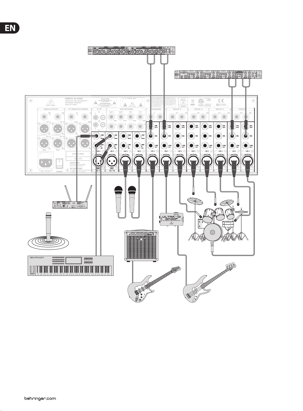
2. Quick Start
2.1 Hook-up example (inputs and inserts)
2-CH COMPRESSOR
4-CH NOISE GATE
Fig. 2.1: Input wiring
Page 7
7 XENYX XL3200/XL2400/XL1600 User Manual
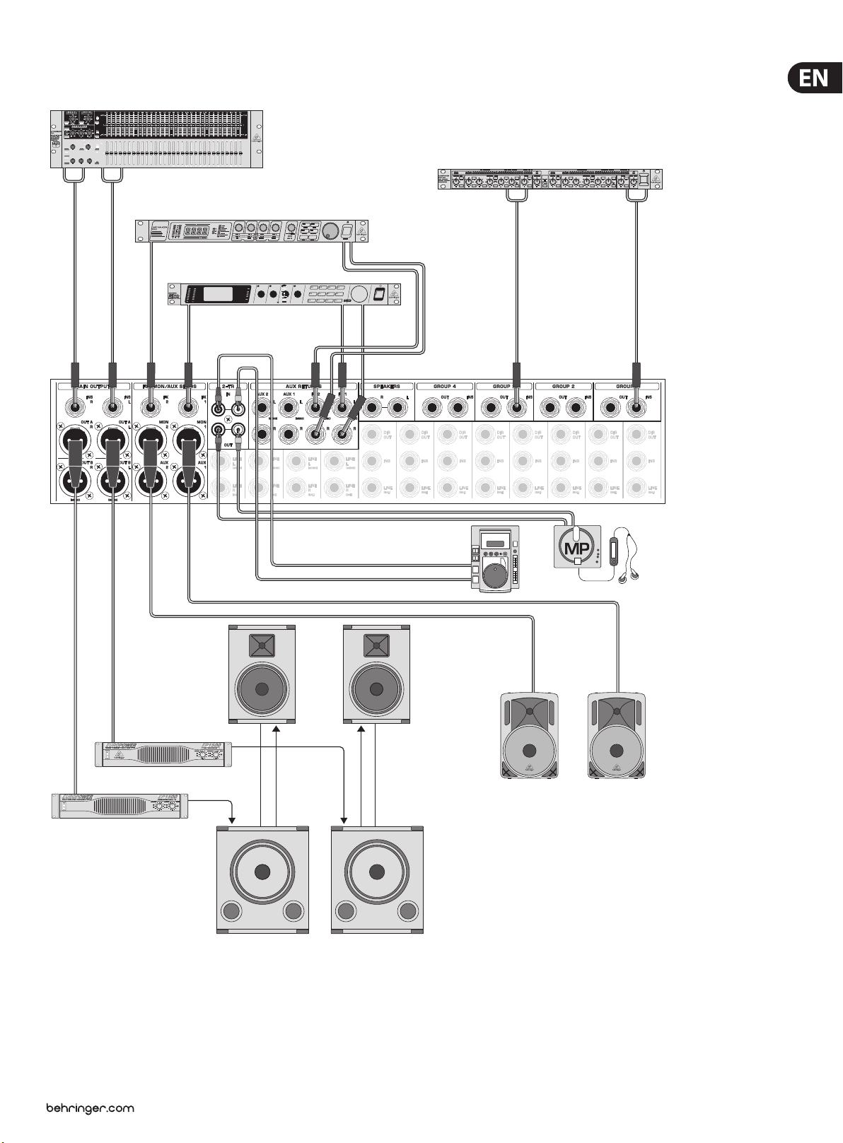
2.2 Hook-up example (outputs)
Graphic Equalizer
Eects Device 2
Eects Device 1
Bus Compressors
Playback Device
Stereo Recording Device
Stage Monitors
Fig. 2.2: Output wiring
P.A.
Page 8

8 XENYX XL3200/XL2400/XL1600 User Manual
3. Installation
3.1 Audio connectors
The ¼" inputs and outputs of the BEHRINGER XENYX mixer are unbalanced
mono TS connectors except for the balanced Line inputs on the mono and stereo
channels as well as the Main Out connectors. Of course, you can use the mixer
with balanced as well as unbalanced ¼" connectors. The CD/TAPE inputs and
outputs are stereo RCA connectors.
◊ Make sure that only competent people install your mixer. They must
be sufficiently grounded during and after the installation process.
Otherwise, electrostatic discharges may negatively affect the
operating characteristics of your equipment.
Unbalanced ¼" TS connector
strain relief clamp
sleeve
tip
sleeve
(ground/shield)
tip
(signal)
Balanced use with XLR connectors
12
3
input
1 = ground/shield
2 = hot (+ve)
3 = cold (-ve)
1
2
3
output
For unbalanced use, pin 1 and pin 3
have to be bridged
Fig. 3.1: XLR connector
Balanced ¼" TRS connector
strain relief clamp
sleeve
ring
tip
sleeve
ground/shield
Fig. 3.3: ¼" TS connec tor
Insert send return ¼" TRS connector
strain relief clamp
sleeve
ring
tip
sleeve
ground/shield
ring
return (in)
tip
send (out)
Connect the insert send with the input and the
insert return with the output of the eects device.
Fig. 3.4: Inser t send/return st ereo plug
¼" TRS headphones connector
strain relief clamp
sleeve
ring
tip
ring
cold (-ve)
tip
hot (+ve)
For connection of balanced and unbalanced plugs,
ring and sleeve have to be bridged at the stereo plug.
Fig. 3.2: ¼" TRS conn ector
sleeve
ground/shield
ring
right signal
tip
left signal
Fig. 3.5: ¼" headphones connector
tip tip
shield
sleevesleeve
Fig. 3.6: RCA ca ble
Page 9

9 XENYX XL3200/XL2400/XL1600 User Manual
4. Connectors
Let's begin with the rear panel where the majority of inputs and outputs
arelocated.
4.1 Power supply
IEC receptacle
The mains connection is a standard IEC receptacle. Anappropriate power cord is
supplied with the unit.
FUSE HOLDER
Before connecting the unit to the mains, ensure that the voltage setting matches
your local voltage. Blown fuses should only be replaced by fuses of the same type
and rating. Please also read the information given in chapter “Specications.”
POWER
Use the POWER switch to turn on the mixing console. The POWER switch
should always be in the “O” position when you are about to connect your
unitto the mains.
To disconnect the unit from the mains, pull out the main cord plug.
Wheninstalling the product, ensure that the plug is easily accessible.
Ifmountingin a rack (XL1600 only), ensure that the mains can be easily
disconnected by a plug pull or by an all-pole disconnect switch on or near
therack.
◊ Please note: The POWER switch does not fully disconnect the unit from
the mains. To disconnect the unit from the mains, pull out the main
cord plug or appliance coupler. When installing the product, ensure the
plug or appliance coupler is readily operable. Unplug the power cord
when the unit is not used for prolonged periods of time.
4.2 Mono inputs
MIC
The balanced XLR input connec ts to microphones, DIboxesand multicores.
(Multicores are cables that have multiple cores and which run from the so-called
stagebox to the mixer.)
◊ Connect the microphone and mute all mixer outputs before turning on
the phantom power to avoid noise when the microphone is turned on.
Please wait for about one minute when switching on the mic until the
voltage is stable. Only then turn on the input amplification.
◊ Caution! Never use unbalanced XLR connectors (pins 1 and
3 interconnected) on the MIC input jacks, if you want to use
phantom power.
+48 V
Phantom power is used for operating a capacitor microphone. A control
LED lights up next to the switch when the phantom power supply is active.
Additionalcontrol LEDs are located in each Trim section of the mixer's
channels. As a rule, dynamic microphones can still be used with phantom
power, providedthey are wired in a balanced conguration. In case of doubt,
contactthemicrophone manufacturer!
SERIAL NUMBER
This is the serial number of the mixing console.
LINE
This is a ¼" jack connector which connects to line-level signal sources
(forexample, keyboards, CD players and wireless microphone receivers).
The input is balanced (TRS connector) but can also be used with unbalanced
connectors (TS connector).
Page 10

10 XENYX XL3200/XL2400/XL1600 User Manual
INSERT
The INS(ert) connector (¼" stereo jack connector) is used to connect to external
signal processors. Here you can hook up a compressor, noise gate or equalizer to
process the signal of a single channel. The insert jack is placed before the fader,
EQ and aux send. Please use an insert cable to connect to the insert point.
DIRECT OUT
This ¼" mono jack connector is a direct output which taps the signal after the
channel fader to route it to a multi-track recorder, for example. By modifying the
circuit board in the unit, the signal can also be tapped pre-fader (see chapter 6).
4.3 Stereo inputs
LINE L (MONO), LINE R
The stereo channels consist of two line inputs (¼" jacks), one for the left and
one for the right channel. The inputs are balanced (TRSconnectors), but it is also
possible to connect to unbalanced plugs (TS connectors). These channels can also
be used as mono channels by connecting to the jack labeled “L” (left).
INSERT
Like the channel inserts, the INS(ert) connectors can be usedto hook up a
dynamics processor or equalizer for further processing of the mix signal on OUT A.
4.5 Subgroup connectors
GROUP OUT 1 - 4
These four GROUP OUTS 1 – 4 carry the signals of the individual subgroups.
Formulti-tracking connect the outputs to the inputs of a multi-track recorder.
INSERT
Each subgroup has an insert jack which is labeled INS. Here you can connect to
a noise gate, compressor or equalizer to process the subgroup signal as a whole.
For example, route your background vocalists to one subgroup bus and then use
a compressor to bring the vocals closer together. This makes it sound more like a
choir rather than a group of individual soloists. The insert point is placed before
the group fader, allowing the dynamics processors (noise gate, compressor, etc.)
to be optimally used and not aected by changes in volume level of the group
fader. Please use an insert cable to connect to the insert point.
SPEAKERS
MIC
The stereo channels also consist of XLR inputs for connecting to microphones
DIboxes and multicores.
+48 V
This is the phantom power for operating capacitor microphones along with the
control LED located next to the switch and in the Trim section of the stereo channels.
4.4 Main mix outputs
OUT A
The OUT A outputs are balanced XLR connectors with a nominal operating level of
+4 dBu and provide the main mixsignal.
The SPEAKERS outputs provide the same signal as the headphone outputs.
Usethese outputs to hook up monitor speakers. This is helpful when the mixing
console is not located close the performance but in a separate room, such as a TV
control room. It is also possible to hook up a stage monitor, ideally one identical
to the monitors being used on stage, to listen in on the sound as perceived from
the stage monitors.
4.6 CD/tape connectors
IN
The CD/TAPE input connectors are used to hook up CD players, tapedecks or other
line-level sources.
OUT
The CD/TAPE output connectors provide the stereo main mix signal to a tape deck
or DAT recorder to record your mix. The signal is taken pre-fader so that it will not
be inuenced by the fader positions.
OUT B
The OUT B outputs provide the MAIN B signal the volume level of which can
becontrolled.
Page 11

11 XENYX XL3200/XL2400/XL1600 User Manual
4.7 FX/Mon/Aux sends
FX 1 and 2
The FX outputs 1 and 2 provide the signals of the eects buses 1 and 2.
Thesesignals may be sent to external eects processors and are routed back over
the AUX-RETURN inputs or separate input channels, for example.
MON 1 and 2
The monitor outputs 1 and 2 provide the signals of the monitor buses.
Thesesignals may be be sent to stage loudspeakers. To prevent interference due
to the long cables being used between stage and mixing console, the outputs
are balanced XLR connectors. What's more, youhave the right connectors when
working with multicores.
5. Control Elements
This chapter describes the various control elements of your mixing console.
Eachcontrol and switch is explained in full detail.
5.1 Mono channels
AUX 1 and 2
The AUX outputs 1 and 2 provide the signals of the AUX buses 1 and 2.
Youcanswitch these buses pre-fader and post-fader so that they may be
usedforeects as well as for monitor applications.
4.8 Aux returns
AUX RETURN
The stereo AUX inputs 1 und 2 let you connect the mixer to additional equipment
(players,eectsprocessors, submixers, etc.). Thesignal is sent to the signal sum.
FX RETURN
The stereo FX RETURN connectors 1 and 2 are linked to the outputs of external
eects processors. Depending on the routing, the signals are sent to the
subgroup or the main mix bus.
4.9 Light and headphone connectors
+48 V
This control LED lights up as long as the phantom power is switched on.
Theswitch is found on the rear panel of the unit.
Trim
The TRIM control adjusts the input gain.
◊ Be sure to set this control fully counter-clockwise before you connect or
disconnect a signal source to or from one of the inputs.
The dial oers 2 dierent value ranges. The rst value range between 0 and +60
refers to the microphone input, indicatingthe degree of amplication applied to
the input's signal. Thesecond value range between -20 and +40 dB refers to the
amplication of the line input. When centered (at12o'clock), the line signals are
neither boosted nor cut.
80 Hz
Press the 80 Hz switch to activate the high-pass lter which blends out
low-frequency noise (-3 dB at 80 Hz, 18 dB/octave).
Equalization
The mono input channels provide 4-band equalization with 2semi-parametric
mids. You can boost or cut the bands up to 15 dB. When in center position (0 dB),
the equalizer has a atresponse.
LAMPS
The LAMPS plugs are for connecting gooseneck lamps with BNC connectors.
Thepower supply is 12 V _ and the total connection load is 5 Watts a lamp.
PHONES
The PHONES outputs (¼" stereo jacks) let you plug in your headphones.
HIGH
The high-frequency range is processed with a shelving lter above 12 kHz.
HIGH MID
A semi-parametric peak lter processes the upper mid range between 400 Hz
and 8 kHz. The FRE control selects the frequency which is boosted or cut by using
the HIGH MID control.
Page 12

12 XENYX XL3200/XL2400/XL1600 User Manual
LOW MID
A second semi-parametric peak lter processes the upper mid range. TheFREQ
control selects the frequency which is boosted or cut by using the HIGHMIDcontrol.
LOW
The low-frequency range is processed with a shelving lter below 80 Hz.
EQ
The EQ push-button switch activates the equalizer. Toggle the EQ to give you a
quick comparison between unprocessed and processed signal.
5.1.1 FX, MON, AUX send paths
AUX
The aux buses are used as additional, exible send paths for various applications.
The AUX control adjusts the volume level of the channel signal in the aux buses.
The sum of all aux signals is determined by the corresponding AUX SEND control
found in the main section. The signals can be routed from the corresponding
AUXSEND outputs. Both the aux send paths can be amplied up to +15 dB and
are pre-fader and post-fader switchable in the main section.
Pre-fader or post-fader:
For most applications using external eects signals, the aux send path should be
switched to post-fader so that the eects volume level in a channel is aected by
the position of the channel fader. If not, the eects signal would be audible even
with a pulled down fader. For monitoring applications, the aux send paths are
usually switched to pre-fader and therefore are not aected by the channel fader.
To oer you the utmost exibilit y, the FX buses can be switched to pre-fader in
each channel. What's more, you may switch the AUX buses in the main section
between pre-fader and post-fader. This gives you a maximum of 6 pre-fader
buses or, alternatively, 4 post-fader plus 2 pre-fader buses.
5.1.2 Channel fader, pan control, mute control, etc.
The send paths FX, MON and AUX allow you to tap the signals of one or more
channels and route them to other outputs. This way you can create individual mixes
for eects (FX) and musicians performing on stage (MON). Using the FX/MON/AUX
send outputs, the mix is fed to the stage loudspeakers and eectsunits.
FX 1 and FX 2
The FX buses are used as send paths to external eects units. The signal is usually
tapped after the channel fader and therefore is aected by the position of the
channel fader.
The FX control adjusts the volume level of the channel signal to the eects unit.
PRE
Press the PRE switch to change the routing of both eects paths from
“post-fader” to “pre-fader.” This way the volume level of the eects signal is not
aected by the channel fader.
Both the FX control on the channel and the corresponding Master FX SEND control
need to be fully turned up as well. Connect the FX Send output to the input of the
eects unit. The eects signal is routed back through the FX Returns found in the
master section.
Monitor 1 and 2:
The monitor buses are used as send paths to stage monitors. The monitor sends
are hardwired pre-fader. This means the volume level of the monitor mix is not
aected when using the channel fader.
The MON control adjusts the volume level of the channel signal in the
monitorbuses.
PAN
The PAN control determines the position of the channel signal in the stereo mix
as well as the subgroup to which the channel signal is routed.
MUTE
The MUTE switch mutes the channel. This means that the channel signal has been
removed from the main mix and subgroups. At the same time the FX, monitor
and aux paths of the respective channel are muted as well. The corresponding
MUTE LED indicates that the channel has been muted.
SOLO
Use the solo function to listen in on a channel. Press the channel's SOLO switch
to hear the signal on your headphones. Simultaneously, the monitor meter ½
switches to the solo signal, allowing you to level the signal correctly (see chapter
X). The signal to be listened in on is tapped either before (PFL, mono) or behind
(AFL,stereo) the channel fader and the pan control (depending on the state of
the PFL/AFL switch. Thecorresponding LED lights up when the solo function
isactivated.
Page 13

13 XENYX XL3200/XL2400/XL1600 User Manual
CLIP
The CLIP LED lights up as soon as the channel's level is too high. In this case,
reduce the channel's input amplication with the TRIM control.
SIG
The SIG LED lights up when a channel's signal is higher than -20 dB. The LED is
not aected by the fader. The signals are indicated even when the fader is pulled
down and the channel is muted.
Fader
The channel fader adjusts the level of the channel signal as part of the main mix
(or submix).
1-2, 3-4, MIX
The routing switch routes the signal to the respective subgroup or the main mix
or both. The XENYX features 4 subgroups. The PAN control determines the group
to which the signal is routed (fully left: Sub 1 or 3, fully right: Sub 2 or 4).
5.2 Stereo channels
5. 2.1 Equalizer stereo channels
The stereo channels provide 4-band equalization. Each frequency band can be
boosted and cut up to 15 dB and has a at response when the controls are in
center position.
HIGH
The HIGH control of the EQ section adjusts the high-frequency range of the
respective channel. This is a shelving lter which boosts and cuts the frequencies
above 12 kHz.
+48 V
This control LED lights up when the phantom power is activated. The switch is
located on the rear panel of the unit.
MIC TRIM
The MIC TRIM control adjusts amplication of the microphone input.
Theamplication ranges between 0 and +60 dB.
◊ Be sure to set this control fully counter-clockwise before you connect or
disconnect a signal source to or from one of the inputs.
80 Hz
Press the 80 Hz switch to activate the high-pass lter which blends out
low-frequency noise (-3 dB at 80 Hz, 18 dB/octave).
LINE TRIM
The LINE TRIM control adjusts the amplication of the LINE input,
rangingbetween -20 and +20 dB. When centered (at 12 o'clock),
thelinesignalisneither boosted nor cut.
HIGH MID
The HIGH MID control adjusts the mid frequency range. Thisisapeak lter which
boosts and cuts the frequencies centered at3 kHz.
LOW MID
The LOW MID control adjusts the mid frequency range. Thisisapeak lter which
boosts and cuts the frequencies centered at 300Hz.
LOW
The LOW control adjusts the low-frequency range. This is a shelving lter which
boosts and cuts the frequencies below 80 Hz.
EQ
The EQ push-button switch activates the equalizer. Toggle the EQ to give you a
quick comparison between unprocessed and processed signal.
5.2.2 Stereo channel FX/MON/AUX send paths
The aux and FX paths of the stereo channels work in principle the same way as
the mono channels. Since the aux buses are mono, the stereo signal needs to be
converted to a mono signal before being routed to these buses.
5.2.3 Channel fader, pan control, mute switch, etc.
BAL(ANCE)
The BAL(ANCE) control has the same func tion as the PAN control on the mono
channels. It determines the relative volume of the left and right input signals
before they are routed to the stereo main mix bus (or to two subgroups).
MUTE
Use the MUTE switch to mute the channel signal. The MUTE LED is illuminated
when the channel is muted
Page 14

14 XENYX XL3200/XL2400/XL1600 User Manual
SOLO
Press the SOLO switch to hear the signal on your headphones and simultaneously
see it on the monitor display ½). The corresponding LED lights up when the solo
function is activated.
CLIP
The CLIP LED lights up as soon as the channel's level is too high. In this case, turnthe
TRIM control to reduce the channel's input amplication until the LED goes out.
SIG
The SIG LED lights up when a channel's signal is higher than -20 dB. The LED is
not aected by the fader. The signals are indicated even when the fader is pulled
down and the channel is muted.
Fader
The channel fader governs the level of the channel signal as part of the main
mix(or submix)
1-2, 3-4, MAIN
The routing switch feeds the signal to the respective subgroup or the main mix
or both. Please note that when using the routing switch to route a stereo signal
to the subgroups the balance control needs to be centered so that the signal is
routed to two groups and remains in stereo.
MAIN MUTE
When the MAIN MUTE switch is pressed, all input channels are muted. The MUTE
LED lights up when the MUTE switch is pressed. Only the CD/TAPE signal will be
routed to the main mix. In this way, you can prevent the microphones from picking
up unwanted sounds or noise that would interfere with CD playback during a break.
The main mix and channel faders can remain in their normal positions while playing
back music from CD (usingthe CD/TAPE inputs, so you don’t lose your mix.
MAIN A
Use this high-precision MAIN fader to control the output level of the main mix.
MAIN B
Depending on the settings of the MAIN B section, the level of the Main B output is
aected by the MAIN A fader.
5.4 Level meters
5.3 Main section
5. 3.1 MAIN A section
BAL(ANCE)
Four high-resolution LED meters indicate the levels of the monitor buses' and
mixer sum's output signals. As soon as you have pressed the solo switch on the
mixing console, the monitor LED meter automatically shows the solo signal.
Themaster signal is alwaysindicated.
1 MON 2
The monitor meters indicate the levels of the monitor buses 1 and 2. In solo mode
(SOLO LED lights up) thePFL signal (mono, only left meter) or the AFL signal
(stereo, left and right meter) are shown. Thisdepends on the state of the PFL and
AFL switch inthe solosection.
SOLO
When a SOLO switch is pressed on the mixing console, not only the corresponding
LED lights up, but also the global SOLO LED. This way you can keep a cool head
when mixing live and don't have to check the whole console to see that one
SOLOswitch is active. Simultaneously this LED indicates that the monitor meters
are in solo mode.
MAIN
The high-precision level meter accurately indicates the output signal
level(MAINOUT A).
The BAL(ANCE) control adjusts the mix of the left and right output signal before
both signals are routed to the MAIN A output. This way the left and right volume
level of the mixer sumcan individually be adjusted if necessary.
Page 15

15 XENYX XL3200/XL2400/XL1600 User Manual
5.5 Subgroups
The XENYX provides 4 subgroups which allow you to feed multiple channels
to mono or stereo mixdowns. Their volume level can be adjusted using the
subgroup faders. For example, createa subgroup with all vocal channels or drum
signals and adjust the volume using the subgroup fader. This way you can keep
track and, at the same time, can process the signal with a compressor via the
subgroup insert.
SIG
The SIG LED lights up when a signal is routed to the subgroup whose level is
higher than -20 dB.
◊ The signal and clip LEDs are not affected by the fader. The signals are
indicated even when the subgroup fader is pulled down.
Fader
The subgroup faders adjust the volume level of the subgroup signal at the
subgroup output. If the MAIN switch is pressed, you can also adjust the
subgroup's volume level in the main mix.
5.6 Further functions of the mastersection
Additionally, you can also use the subgroup outputs as sends for a
multitrackrecorder.
PAN
The PAN control adjusts the position within the stereo image.
MAIN
The MAIN switch routes the subgroup signal to the main mix.
With the PAN control you can adjust the signal to the left side of the stereo
image (PAN turned fully left), to the right side of the stereo image (PAN turned
fully right) or to both sides (PAN in center position) of the stereo main mix.
Forexample, when creating a stereo submix with the subgroups 1 and 2, group1
should be adjusted to the left and group 2 to the right side of the main mix in
order to maintain a balanced stereo image. In case you have created a mono
submix with only one subgroup, be sure to center the PAN control so that the
signal is not only heard on one side.
SOLO
The SOLO switch routes the subgroup signal to the AFL bus (Solo In Place) orPFL
bus (Pre Fader Listen), so that you can monitor the subgroup signal without
aecting the main or sub output signals. The signal to be monitored is taken
either pre (PFL, mono) or post-subgroup fader (Solo, stereo), depending on the
position of the SOLO/PFL switch. The SOLO LED illuminates when the SOLO switch
is pressed.
5. 6.1 Talkback
The talkback function of the XENYX allows you to communicate with people on
stage. The talkback signal can be routed to the dierent bus outputs.
MIC
CLIP
The CLIP LED lights up as soon as the subgroup signal's level is too high.
Inthiscase, pull down the channels' faders routed to this group.
Here you can plug in the microphone for talkback use.
LEVEL
The LEVEL control adjusts the volume level of the talkbacksignal.
Page 16

16 XENYX XL3200/XL2400/XL1600 User Manual
MON, AUX, GROUP, MAIN
These push-button switches (MON, AUX, GROUP and MAIN) determine to which
outputs and buses the talkback signal is to be routed. Then, turn on the talkbalk
microphone. Pressand hold down the push-button switch while speaking into
themicrophone.
5.6.2 SOLO
SOLO LEVEL
The SOLO LEVEL control adjusts the volume level of all solo signals routed to the
headphone and loudspeaker outputs.
PFL/AFL
Press the PFL/AFL switch to change the solo functionality from PFL mono
(pre-fader listen) to AFL stereo. The LED next to the switch indicates the selected
state. In PFL mode, the signal is tapped before the fader when pressing the solo
switch. In AFL mode, the signal is tapped behind the fader and in stereo for a
correct positioning within the stereo image.
If you adjust the signal's level with the TRIM control, select the PFL mode so that
the displayed level is not aected by the channel fader.
5.6.3 CD/TAPE
LEVEL
LEVEL
The LEVEL control adjusts the volume level of the signal routed to the
MAINBoutput.
STEREO/MONO
The STEREO/MONO switch changes the Main B signal from mono to stereo
depending on the situation. For example, a mono signal is usually used for a
center cluster.
PRE/POST
The PRE/POST switch is used to determine whether the signal is tapped in front
or behind the MAIN A fader.
5.7 FX master section
The LEVEL control adjusts the signal in the main mix, for example,
whenconnecting the CD/tape inputs to a CD player.
MAIN
Press the MAIN switch to route the CD signal to the main output. The CD signal
remains audible even when the MAIN MUTE switch is pressed. This allows you to
play music during performance breaks.
5.6.4 PHONES/SPEAKER section
The PHONES A/B control adjusts the volume level of the headphone output.
◊ IMPORTANT! High volume levels may damage your hearing and/or
your headphones/loudspeakers. To avoid switch-on/off thumps from
the console and any downstream devices, always make sure that the
power amp(s) or active speaker(s) are the last components that are
switched on and the first to be switched off. Always make sure that the
appropriate volume is set.
SPKR
The Speaker control adjusts the volume level of the SPEAKERS outputs.
SOURCE
The SOURCE push-button switch selects the signal source for the headphone
and loudspeaker outputs (main or CD/TAPE signal). Pressing a solo switch
routes the solo signal to these outputs and is not aected by the SOURCE
push-buttonswitch.
MAIN B section
This section has additional inputs for signals which do not require further signal
processing. Ideally, usethem for signals returning from external eects units.
This is why these inputs are referred to as FX returns. It is possible to route the
eect signals to the monitors and subgroups. This way the stereo channels can be
used for additional stereo signals, such as keyboards, etc., and not for eects
units' signals which require functions like fader, routing, solo and mute.
The mixer sum can also be routed to the MAIN B output which may be connected
to a separate power amplier. This way the sum can be sent to multiple zones
and various loudspeaker groups (for example, center clusters and front lls).
Onemay also want to connect a stereo recording system for live recording.
FX SEND
This is the master FX SEND control for adjusting the volume of all FX send signals
at the corresponding FX send jacks and at the inputs of the built-in eects
processor. Use it to control the master signal of all FX1/FX 2 signals from the
input channels. Whenneither of the FX SEND controls is turned up, theeects
processor will not receive a signal.
Page 17

17 XENYX XL3200/XL2400/XL1600 User Manual
MON
Use the MON controls to add an eect signal to the monitor buses 1 and 2.
Forthis application, the eects unit needs a signal: turn up the respective master
FXSEND control and the FX send controls on the channel strips (34) and pull up
the channel faders.
1-2, 3-4
These selector switches route the eec t signal to the main mix or to the subgroups
1-2 or 3-4. For example, if you create a subgroup for a choir, you need to feed the
eect, which processes the vocal signal, to the same subgroup so that all signals
can be adjusted equally. In this case it doesn't mat ter that the FX sends are routed
post-fader as long as the choir's volume level is adjusted with the subgroup fader.
Otherwise, the eect signal is perceived as unaected in the main mix.
MUTE
The MUTE switch mutes the eect return path. Use this function to deactivate
the reverb eect of a vocalist who makes announcements between songs.
Thecorresponding MUTE LED indicates that the channel is muted.
SOLO
Press the SOLO switch to listen in on the eect signal on the
headphones/speakers as well as see it on the monitor meter ½.
Thecorresponding LED lights up when the solo function is activated.
FX RETURN
The FX return fader adjusts the volume level of the returned eect signal in the
main mix and subgroups (this depends on the routing switch you have pressed).
MUTE
Each monitor send has a MUTE switch and MUTE LED.
SOLO
For acoustic control of the stage sound, use the SOLO switch to feed the monitor
signal to the headphone and speaker output. If you connect the speaker output to
a monitor that is identical with the monitor speakers on stage, you can tell how
the stage sound is perceived.
5.9 AUX master section
This section is split up in an aux send section (lef t side) and an aux return
section(right side). The aux send paths 1 and 2 can individually be switched from
pre-fader to post-fader depending on whether you want to use them as monitor
or eect signal paths. As with all outputs, both aux master outputs feature 10 dB
headroom as well as a MUTE and SOLO switch.
In the aux return section, you can adjust the signals of the devices (CD player,
eects unit, submixer, etc.) connected to the aux inputs which are then routed to
the monitor buses and the main mix.
PRE/POST
5.8 Monitor send section
The monitor send section merges the monitor signals of all channels. Thenthe
mix is sent to the monitor outputs. The monitor fader provides precise
adjustment and optical control of the monitor outputsignals.
This is the global PRE/POST switch for the aux buses. For utmost exibility,
eachAUX bus can individually be switched from pre-fader to post-fader.
AUX SEND
The Master AUX SEND controls 1 and 2 adjust the signals' volume level of the
respective aux send connector. This way you adjust the sum of the AUX 1 and
AUX2 signals on the input channels.
MUTE
The MUTE switch mutes the aux outputs.
SOLO
The aux send signals can individually be listened to using the SOLO function.
MON
A signal sent from AUX RETURN can be added to the stage mix using the
MONcontrol.
AUX RETURN
The AUX RETURN controls adjust the volume level of the aux return signals in the
main mix.
SEND
The SEND faders control the output level of the monitor buses. Each fader is
60mm long and features 10 dB headroom.
Page 18

18 XENYX XL3200/XL2400/XL1600 User Manual
6. Modications
◊ These modifications require soldering. Attempt only if you are
experienced in using an iron on PCBs. Otherwise, refer to qualified
personnel. After modification the warranty becomes void.
◊ We wish to be absolutely clear that BEHRINGER cannot be held
responsible after you start disassembling your XENYX. If you make
much of your warranty privileges, think again.
◊ Links should not be threaded into the holes on the PCB, but are to
be soldered to the tinned areas around the holes. Bend the links a
little upwards.
6.1 Mon/Aux sends > post-EQ
Pre-fader switched monitor sends and aux sends are tapped o before the
equalizer. Do you prefer post-EQ? What are you waiting for? You don't have to
look far—the necessary information is found on the bottom side of the unit.
◊ Make sure to turn off the mixer and disconnect it from the mains before
removing the cover.
1) Strip the PRE EQ lead.
7. Specications
Mono Inputs
Microphone Inputs (XENYX Mic preamp)
Type XLR connector, electronically balanced,
discrete input circuit RF rejection lters
Mic E.I.N.1 (20 Hz - 20 kHz)
@ 0Ω source resistance -127dB / 129.7dB A-weighted
@ 50Ω source resistance -126dB / 128.3dB A-weighted
@ 150Ω source resistance -125dB / 126.5dB A-weighted
Frequency Response
To Direct Out <10Hz - 50kHz (-1dB)
<10Hz - 100kHz (-3dB)
To Insert Send <10Hz - 90kHz (-1dB)
<10Hz - 170kHz (-3dB)
Gain range 0dB to +60dB
Max. input level +24dBu @0dB Gain
Impedance approx. 2.6kΩ balanced
Signal-to-noise ratio 120dB / 122dB A-weighted
(0dBu In @ +22dB Gain)
2) Solder a POST EQ link into place.
3) Make these modications to as many channels as required (does it have to be
all of them?).
6.2 Direct Out > pre-fader
If you prefer to use the Direct Out pre-fader than post-fader, the signal needs
to be tapped o before the fader and not after the fader. To perform this
modication, nd the label “DIR-OUT” on the circuit board.
◊ Make sure to turn off the mixer and disconnect it from the mains before
removing the cover.
1) Strip the POST FADER lead.
2) Solder a PRE FADER link into place.
Distortion (THD + N) typ. 0.0008%
Line Input
Type ¼" TRS jack, electronically balanced
Impedance approx. 20kΩ balanced,
approx. 10kΩ unbalanced
Gain range -10dB to +40dB
Max. input level +22dBu @ 0dB Gain
Channel Inserts
Type ¼" TRS jack, unbalanced
Max. input level +22dBu
Channel Direct Outs
Type ¼" TRS jack, balanced
Impedance approx. 75Ω balanced
Max. input level +22dBu
Crosstalk
2
Main fader closed 100dB
Channel muted 90dB
3) Make these modications to as many channels as required.
Channel fader muted 85dB
Frequency Response (Mic In → Main Out)
<20Hz - 20kHz +0dB / -1dB
<10Hz - 160kHz +0dB / -3dB
Page 19

19 XENYX XL3200/XL2400/XL1600 User Manual
Stereo Inputs
Type 2 x ¼" TRS jack, balanced
Impedance approx. 20kΩ balanced,
approx. 10kΩ unbalanced
Gain range -20dB to +20dB
Max. input level +22dBu @ 0dB Gain
CD/Tape In
Type RCA connector
Impedance approx. 10kΩ
Max. input level +22dBu
Equalizer
EQ Mono Channels
LOW 80Hz / ±15dB
HIGH MID 100Hz to 2kHz / ±15dB
LOW MID 400Hz to 8kHz / ±15dB
HIGH 12kHz / ±15dB
LOW CUT 80Hz, 12dB/oct.
EQ Stereo Channels
Subgroup Outputs
Type ¼" TRS jack, unbalanced
Impedance approx. 75Ω
Max. output level +22dBu
Group Inserts
Type ¼" TRS jack, unbalanced
Max. output level +22dBu
Main Outputs A/B
Type XLR connector, electronically balanced
Impedance approx. 240Ω balanced,
approx. 120Ω unbalanced
Max. output level +25dBu
Main Inserts
Type ¼" TRS jack, unbalanced
Max. input level +22dBu
Speakers
LOW 80Hz / ±15dB
LOW MID 300Hz / ±15dB
HIGH MID 3kHz / ±15dB
HIGH 12kHz / ±15dB
Channel inserts
Type ¼" TRS jack, unbalanced
Max. input level +22dBu
AUX/MON send
Type XLR connector, electronically balanced
Impedance approx. 75Ω
Max. output level +22dBu
FX send
Type ¼" TRS jack, balanced
Impedance approx. 75Ω
Max. output level +22dBu
AUX/FX Returns
Type ¼" TRS jack, unbalanced
Impedance approx. 75Ω
Max. output level +22dBu
Phones A/B Output
Type ¼" TRS jack, unbalanced
Max. output level +22dBu / 600Ω
CD/Tape Output
Type RCA connector
Impedance approx. 1kΩ
Max. output level +15dBu
Main Mix System Data3 (Noise)
Main mix @ -∞, -110dB / -114dB A-weighted
channel fader @ -∞
Main mix @ 0dB, -95dB / -98dB A-weighted
channel fader @ -∞
Main mix @ 0dB, -92dB / -95dB A-weighted
channel fader @ 0dB
Type ¼" TRS jack, unbalanced
Impedance approx. 20kΩ
Max. input level +22dBu
Page 20

20 XENYX XL3200/XL2400/XL1600 User Manual
Power Supply
Power Consumption
XL3200 70 W
XL2400 65 W
XL1600 60 W
Fuse (100 - 240V~, 50/60Hz) T 2,0A H 250V
Mains connector Standard IEC receptacle
Physical/Weight
Dimensions (H x W x D)
XL3200 7.1 x 21.3 x 35.8"
180 x 910 x 540 mm
XL2400 7.1 x 21.3 x 27.8"
180 x 705 x 540 mm
XL1600 7.1 x 21.3 x 19.5"
180 x 495 x 540 mm
Weight (Net)
XL3200 32.8 lbs / 14.9 kg
XL2400 25.8 lbs / 11.7 kg
XL1600 19.0 lbs / 8.6 kg
1) Equivalent Input Noise
2) Measur ing conditions: 1 k Hz rel. to 0 dBu; 20 Hz - 20 kHz; lin e input; main output ; unity gain
3) 2 0 Hz - 20 kHz; measured a t main output. Chann els 1 - 4 unity gain; EQ f lat; all channels on main mix ;
channels ¹⁄₃ as far lef t as possible; chan nels ²⁄₄ as far right a s possible; refere nce = +6 dBu
BEHRINGER i s constantly str iving to maintain the h ighest profess ional standards. A s a result of these e ffort s,
modific ations may be made f rom time to time to exi sting product s without prio r notice. Specif ications and
appearance m ay differ fro m those listed or illus trated.
Page 21

21 XENYX XL3200/XL2400/XL1600 User Manual
Page 22

22 XENYX XL3200/XL2400/XL1600 User Manual
FEDERAL COMMUNICATIONS
COMMISSION COMPLIANCE
INFORMATION
XENYX XL3200/XL2400/XL1600
Responsible Party Name: MUSIC Group Services US Inc.
Address: 18912 North Creek Parkway,
Suite 200 Bothell, WA 98011,
USA
Phone/Fax No.: Phone: +1 425 672 0816
Fax: +1 425 673 7647
XENYX XL3200/XL2400/XL1600
complies with the FCC rules as mentioned in the followingparagraph:
This equipment has been tested and found to comply with the limits for a ClassB
digital device, pur suant to part 15 of the FCC Rules. These limits are designed
to provide reasonable protection against harmful interference in a residential
installation. This equipment generates, uses and can radiate radio frequency
energy and, if not installed and used in accordance with the instructions, may cause
harmful interference to radio communications. However, there is no guarantee that
interference will not occur in a particular installation. If this equipment does cause
harmful interference to radio or television reception, which can be determined
by turning the equipment o and on, the user is encouraged to try to correct the
interference by one or more of the followingmeasures:
• Reorient or relocate the receiving antenna.
• Increase the separation between the equipment and receiver.
• Connect the equipment into an outlet on a circuit dierent from that to which the
receiver is connected.
• Consult the dealer or an experienced radio/TV technician forhelp.
This device complies with Part 15 of the FCC rules. Operation is subject to the
following two conditions:
(1) this device may not cause harmful interference, and
(2) this device must accept any inter ference received, including inter ference that may
cause undesired operation.
Important information:
Changes or modications to the equipment not expressly approved by MUSIC Group
can void the user’s authority to use the equipment.
Page 23

We Hear You
 Loading...