

Page 1
T1954
®
TUBE ULTRAFEX
Page 2

TUBE ULTRAFEX T1954
2
Page 3

TUBE ULTRAFEX T1954
FOREWORD
Dear Customer,
We thank you for expressing your confidence in BEHRINGER products by purchasing the BEHRINGER
TUBEULTRAFEX. It is one of my most pleasant tasks to write this preface, as our engineering team has made
it possible to enhance the traditional tube circuitry design (particularly for our VINTAGER series of products),
and adapt it to meet the high sound quality and dynamics requirements of modern, pro-level audio technology.
The fact that we are still fascinated by antique tube radios and amps as well as the fine and warm tonal
character that we usually associate with them, are the reasons why vacuum tubes have kept their ground even
in state-of-the-art circuit topologies used especially in professional audio technology or high-end devices. We
are particularly proud that we have found an extremely effective symbiosis between solid-state and tube
technologies making them affordable to anybody interested in audio technology. As always, our top-priority
concern when developing this device was the demanding end user, in other words: you. It was our major goal
to meet your demands. Sure, it meant a lot of hard work to develop such a product, but the fun has made it all
worthwhile. The shine in the eyes of the many interested musicians at the Music Fair 1997, when they saw our
VINTAGER models for the first time, was a lasting incentive driving our development efforts.
It is our philosophy to share our joy with you, because you are the most important member of the BEHRINGER
family. With your highly competent suggestions for new products youve greatly contributed to shaping our
company and making it successful. In return, we guarantee you uncompromising quality (manufactured under
ISO9000 certified management system) as well as excellent technical and audio properties at an extremely
favorable price. All of this will enable you to fully unfold your creativity without being hampered by budget
constraints.
We are often asked how we can make it to produce such high-grade devices at such unbelievably low prices.
The answer is quite simple: its you, our customers! Many satisfied customers means large sales volumes
enabling us to get better conditions of purchase for components, etc. Isnt it only fair to pass this benefit back
to you? Because we know that your success is our success, too!
I would like to thank all people whose help on Project TUBEULTRAFEX has made it all possible. Everybody
has made very personal contributions, starting from the designers of the unit via the many staff members in our
company to you, the user of BEHRINGER products.
My friends, its been worth the trouble!
Thank you very much,
Uli Behringer
3
Page 4
TUBE ULTRAFEX T1954
®
TUBEULTRAFEX
Professional, multi-purpose sound enhancement system for high-end studio and stage applications
T1954
4
Page 5

TUBE ULTRAFEX T1954
TABLE OF CONTENTS
1. INTRODUCTION .....................................................................................................................6
1.1 The Design Concept ........................................................................................................................ 6
1.2 Before You begin ............................................................................................................................. 6
1.3 Control Elements ............................................................................................................................ 7
2. OPERATION .......................................................................................................................... 10
2.1 Introduction ................................................................................................................................... 10
2.2 The Position of the TUBE ULTRAFEX in the Signal Path ............................................................... 10
2.3 Basic Setting .................................................................................................................................11
2.4 Adjustment of the Bass Processor................................................................................................. 11
2.5 Adjustment of the Noise Reduction System ................................................................................... 11
2.6 Adjustment of the Enhancer/Exciter System .................................................................................. 11
2.7 Adjustment of the Tube Stage ....................................................................................................... 12
2.8 Adjustment of the Surround Processor .......................................................................................... 12
3. APPLICATIONS .....................................................................................................................12
3.1 Sound Enhancement during Replay ..............................................................................................12
3.2 Sound Enhancement during Recording.......................................................................................... 12
3.3 Enhancing the Sound of Subgroups, Monitor and Effect Paths ...................................................... 13
3.4 Enhancing the Sound of Tape Duplication ......................................................................................13
3.5 Enhancing the Sound of Instruments ............................................................................................. 13
3.6 Enhancing the Sound of P.A. Systems..........................................................................................14
3.7 Sound Enhancement in HiFi and Video ......................................................................................... 14
4. TECHNICAL BACKGROUND .............................................................................................. 14
4.1 The BEHRINGER TUBE ULTRAFEX ... ......................................................................................... 14
4.2 Psycho-acoustic Background ....................................................................................................... 15
4.3 On Psycho-acoustic Devices ........................................................................................................ 15
4.3.1 Frequency correction .......................................................................................................... 16
4.3.2 Phase shifting ..................................................................................................................... 16
4.3.3 Artificial harmonics generation ............................................................................................16
4.4 The Bass Processor of the TUBE ULTRAFEX ............................................................................... 16
4.5 The Surround Processor of the TUBE ULTRAFEX ......................................................................... 17
4.6 The Vacuum Tubes of the TUBE ULTRAFEX ................................................................................. 17
4.6.1 UTC circuit .......................................................................................................................... 17
4.6.2 Tube history ........................................................................................................................ 18
4.6.3 Design and functional principle of tubes .............................................................................. 18
4.6.4 Properties of tubes.............................................................................................................. 19
4.6.5 The best of both worlds ....................................................................................................... 20
4.6.6 Studio applications .............................................................................................................. 20
5. INSTALLATION ..................................................................................................................... 20
5.1 Rack mounting .............................................................................................................................. 21
5.2 Mains Connection ......................................................................................................................... 21
5.3 Audio Connections ........................................................................................................................ 21
5.4 Transformer-balanced Outputs (optional) ....................................................................................... 22
6. SPECIFICATIONS .................................................................................................................. 23
7. WARRANTY ........................................................................................................................... 24
5
Page 6

TUBE ULTRAFEX T1954
1. INTRODUCTION
In purchasing the new TUBEULTRAFEX T1954, you have acquired an extremely efficient and universal sound
processor which combines the sound enhancement features of the ULTRAFEX series with the tube sound of
the BEHRINGER ULTRA-TUBE technology. Since its announcement of the first ULTRAFEX model in year
1990, it has caused a sensation. This high-end sound enhancement processor is based on our many years of
experience and discoveries in the field of psycho-acoustics. The TUBEULTRAFEX finds widespread application throughout the world, in renowned studios, sound reinforcement systems as well as in broadcast and TV
studios.The sound precision and flexibility of the functions are the main outstanding features of this high-end
unit. The TUBEULTRAFEX is our state-of-the-art sound enhancement system offering a special combination
of sound improvement designs. The unit can be used wherever professional sound improvement is required.
The BEHRINGER TUBEULTRAFEX is the no-compromise answer when the situation demands a no-compromise solution.
Advanced BEHRINGER technology
The philosophy behind BEHRINGER products guarantees a no-compromise circuit design and employs the
best choice of components. The TUBE ULTRAFEX uses high-quality resistors and capacitors with very tight
tolerances, high-grade switches, low-noise operational amplifiers (type 4580) as well other selected components.
Additionally, the unit is manufactured in compliance with the ISO9000 certified management system.
1.1 The Design Concept
Compared to its predecessors, the TUBEULTRAFEX offers several advanced features and we have succeeded
in dramatically refining the audio qualities. The unit now features our new UTC tube circuitry and a new L/C filter
switch which offers more power in the bass area. Beside that a new VSP (Variable Sound Processing) circuitry
has been added to allow you to use simultaneous exciter and enhancer sound processing.
Since the introduction of the first psycho-acoustic Processors, technology in this field has made tremendous
progress. Although the fundamental principles of enhancer and exciter technology have been well-known for a
long time, engineers have been able to refine and improve the essential components over and over again. The
BEHRINGER company has also contributed considerably to this development:
With the introduction of our Natural Sonic processor, we have set new standards. Previously encountered
problems of restricted leveling range, plus increased noise level and audible distortion during signal processing, are typical shortcomings of conventional circuit designs. They were completely solved by the development
of new circuitry.
The BEHRINGER TUBE ULTRAFEX is equipped with different sound enhancement features which stand for a
new achievement in the history of sound processors: The legendary BEHRINGER Natural Sonic principle in
combination with the Variable Sound Processing circuitry (VSP) and the integrated Noise Reduction system
offer presence and transparency for your music without receiving unwanted noise. The Bass Processor additionally adds power to the bottom end. The innovative Surround Processor enables extra depth and width for
stereo signals. As a special feature the TUBE ULTRAFEX comes with the new ULTRA-TUBE technology
(UTC) that adds warmth and translucency to your music.
In the TUBE ULTRAFEX two selected 12AX7/ECC83 vacuum tubes are used. These triodes are capable of
handling a large dynamic range with little microphony. In addition to that their relative ruggedness and above
average life span and you can see why its one of the most popular and reliable pre-amp tubes on the market.
These features also ensure you their availability for many years to come.
Failsafe relays have been incorporated into the design of the BEHRINGER TUBE ULTRAFEX, which automatically and silently bypass the unit in the event of power supply disconnection or failure. These relays are also
active at switch-on to isolate the TUBE ULTRAFEX until the power rails have settled, thus preventing the
possibility of a potentially damaging switch-on thump.
1.2 Before You begin
Your BEHRINGER TUBE ULTRAFEX was carefully packed in the factory and the packaging was designed to
protect the unit from rough handling. Nevertheless, we recommend that you carefully examine the packaging
and its contents for any signs of physical damage, which may have occurred in transit.
6
1. INTRODUCTION
Page 7
TUBE ULTRAFEX T1954
+ If the unit is damaged, please do not return it to us, but notify your dealer and the shipping
company immediately, otherwise claims for damage or replacement may not be granted.
Shipping claims must be made by the consignee.
The BEHRINGER TUBE ULTRAFEX fits into two standard 19" rack units of space. Please allow at least an
additional 4" depth for the connectors on the back panel.
Be sure that there is enough space around the unit for cooling and please do not place the TUBE ULTRAFEX
on high temperature devices such as power amplifiers etc. to avoid overheating.
+ Before you connect your TUBE ULTRAFEX to the mains, please make sure that your local
voltage matches the voltage required by the unit!
The mains connection of the TUBE ULTRAFEX is made by using a mains cable and a standard IEC receptacle.
It meets all of the international safety certification requirements. Please make sure that all units have a proper
ground connection.
+ Please ensure that only qualified persons install and operate the TUBE ULTRAFEX. During
installation and operation the user must have sufficient electrical contact to earth. Electrostatic charges might affect the operation of the TUBE ULTRAFEX!
Additional information you will find in Chapter 5 INSTALLATION.
As a standard the audio inputs and outputs on the TUBE ULTRAFEX are fully balanced. If possible, connect
the unit to other devices in a balanced configuration to allow for maximum interference immunity. The automatic servo function detects unbalanced connections and compensates the level difference automatically
(6-dB correction).
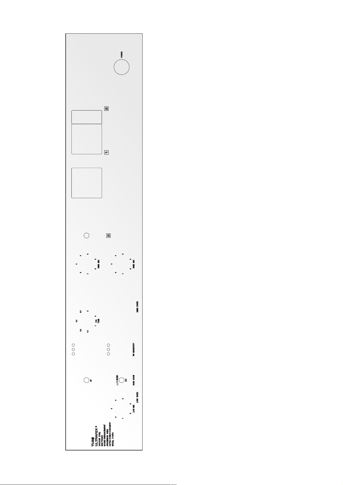
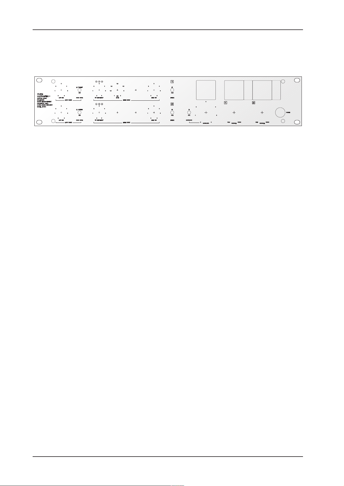
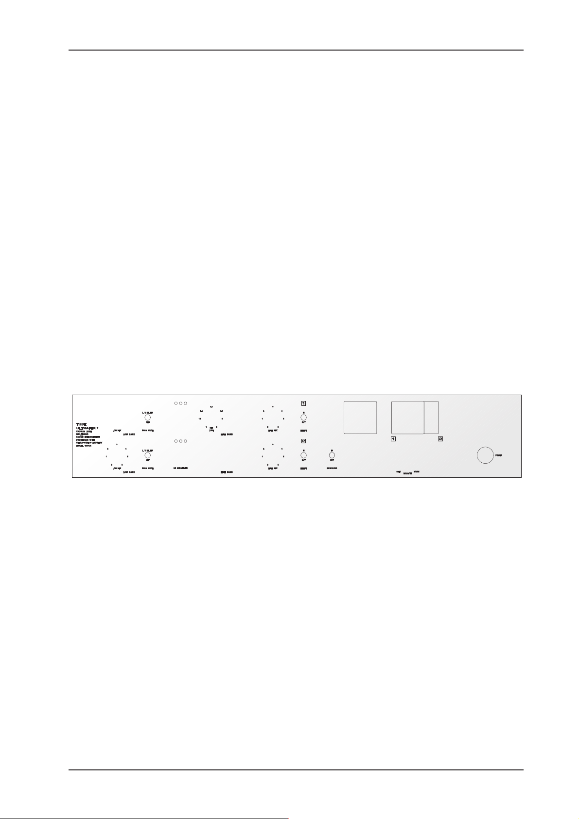
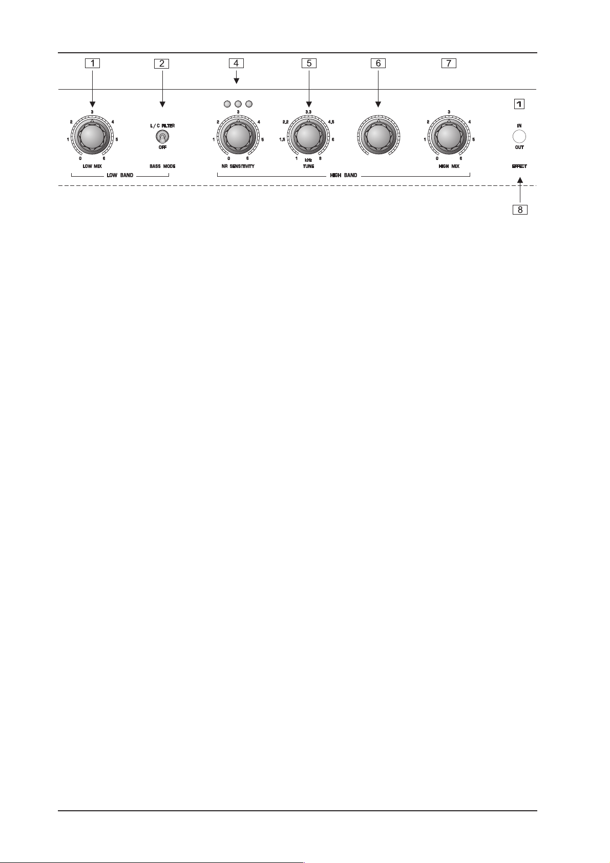
1.3 Control Elements
7
Page 8
TUBE ULTRAFEX T1954
8
Page 9

TUBE ULTRAFEX T1954
9
Page 10

TUBE ULTRAFEX T1954
17
AUDIO IN. These are the audio inputs of your TUBEULTRAFEX, available both as balanced 1/4" TRS
connectors and XLR connectors.
18
AUDIO OUT. These are the audio outputs of your TUBEULTRAFEX. Matching phone jack and XLR
connectors are wired in parallel. These outputs can be transformer-balanced by retrofitting the optional
output transformer OT-1. The reference level is +4dBu and the maximum level comes to +21dBu.
2. OPERATION
2.1 Introduction
The BEHRINGER TUBE ULTRAFEX combines the legendary sound enhancement possibilities with the musical tube sound of the UTC technology.
The BEHRINGER UTC technology
The BEHRINGER TUBE ULTRAFEX uses our newly developed UTC technology, a development resulting from
two years of intensive research work by our engineering team. This technology overcomes the problems
related to tube circuitry (see Chapter 3) and generates upper harmonics even at low levels to give your recordings more warmth and power.
The BEHRINGER Natural Sonic Processor: sound enhancement of classical and pop music
The BEHRINGER Natural Sonic principle is based on frequency-selective phase shifting in conjunction with
program-dependent equalization and pulse enlargement. An automatic and natural correction during signal
processing offers a quality of sound enhancement that has been almost inconceivable until now. Programdependent control permits the musical and unobtrusive transparency required for classical music material,
yet also provides the necessary brilliance for pop recordings. Owing to its dynamic control, and in contrast with
conventional units, the circuitry does NOT introduce any additional noise, non-related harmonics or distortion.
The VSP (Variable Sound Processing) circuit
The new VSP (Variable Sound Processing) circuit used for the first time in the TUBE ULTRAFEX, allows for
variably fading over from enhancer to exciter mode. Using the PROCESS control clockwise, the exciter circuit
comes in additionally to provide a variable and carefully adjusted processing of high frequencies. The result is
an increased brilliance and transparency. Fading over from one effect to the other can thus adapt the effects
perfectly to the respective program material.
Built-in Noise Reduction system
Due to physical reasons, exciters and enhancers principally increase noise of the processed program material. Therefore, we have incorporated a switchable noise reduction system which is capable of automatically
fading out any additional noise.
Bass Processor
The TUBE ULTRAFEX is equipped with a separate Bass Processor which allows for sound enhancement in the
lower frequency band. The newly developed, switchable LC filter produces a more dry and substantial bass
sound. Processing the bass range means an optimum completion of high-frequency processing and opens up
new dimensions in the field of sound processing.
Surround Processor
A switchable Surround Processor has also been integrated into the TUBE ULTRAFEX. With this processor the
intensity of the stereo effect can be dramatically improved (see chapter 4.5 for additional information).
2.2 The Position of the TUBE ULTRAFEX in the Signal Path
The perfect position for inserting the TUBE ULTRAFEX in the signal path depends on the terms of reference:
The stereo structure of the TUBE ULTRAFEX suggests to connect the device with the subgroup or main
inserts. If your mixer does not have inserts you can also position the TUBE ULTRAFEX between the Main Mix
output and a recording device. Moreover the use between signal processors and a mixer makes sense.
Of course, you can also use the channels of the TUBE ULTRAFEX independent of each other. So you can
process two mono signals independently.
10
2. OPERATION
Page 11

TUBE ULTRAFEX T1954
2.3 Basic Setting
We recommend setting the controls as indicated in the following section. This will give you a better idea of
switch and control functionality:
s Set the SURROUND IN/OUT switch to position OUT and the L/C FILTER switch to position OFF. Turn the
TUNE controls to center position and all other controls fully CCW. Set the EFFECT IN/OUT switch to
position IN.
s You may find that getting to know a dual channel processor like the TUBEULTRAFEX is easier when you
concentrate on one channel first. If you have a mixer connect the TUBEULTRAFEX to the insert of one
channel only. See also the Chapters 2.1 and 3 for the right connection.
2.4 Adjustment of the Bass Processor
Apart from processing the upper harmonic ranges, users of the BEHRINGER TUBEULTRAFEX have access
to an innovative Bass Processor.
The numerous stages of processing during the recording, reproduction, copying and effecting processes,
increasingly delay the phase of the bass frequencies, when compared to the remaining frequency ranges. This
is why the low-frequency range suffers from a loss in power and fundamental bass definition.
With the help of frequency-selective phase shift combined with sub-bass boost, the Bass Processor of the
BEHRINGER TUBEULTRAFEX is capable of compensating for this loss, giving the program material new
bass presence. Using the MODE switch, you can select between two different bass sounds.
Be extremely careful when using the Bass Processor: excessive use of the Bass Processor might lead to
speaker damage. The amplified sub-bass frequencies may well place a heavy load on the amplifier and the
woofers. Therefore, carefully adjust the Bass Processor and observe the power rating of your system!
2.5 Adjustment of the Noise Reduction System
With the SENSITIVITY control you can now adjust the noise reduction system.
The noise reduction system prevents noise from becoming audible during pauses and soft pieces in the
program material. The enhancer/exciter signal is reduced dynamically when the signal drops below the value
set by the NR SENSITIVITY control. The NRSENSITIVITY also controls the sensitivity of the enhancer/exciter.
When the NRSENSITIVITY control is turn clockwise more harmonics are added by the enhancer/exciter
section. Turn the control counter-clockwise with lower signals and further clockwise for loud signals.
Use the three LEDs above the control to monitor the effect to avoid pumping or other side effects.
When more LEDs light up the enhancer/exciter is increasingly active. When all three light up the Noise
reduction system is inactive. When none light up the effect signal is muted, the enhancer/exciter is inactive.
Try to set it up so that at soft pieces only one LED lights up and all three light up at loud pieces.
+ When the NRSENSITIVITY control is turned so far counter-clockwise that no LEDs light up, the
effect signal is muted and the settings for the enhancer/exciter are inactive. When this happens, simply turn up the NRSENSITIVITY until the LEDs light up.
2.6 Adjustment of the Enhancer/Exciter System
Now you can start processing the high frequencies. Turn the HIGHMIX control clockwise and notice how the
high frequencies become more pronounced and transparent. When you turn the TUNE control, the frequency
at which the effect begins is changed, the PROCESS control changes the way the effect operates. When set
to ENHANCER only frequencies that are present in the original signal are used, when set to EXCITER artificial
harmonics are generated based on the frequencies present in the signal. When the control is turned clockwise
the sound gains brilliance but also sharpness. Use the exciter on instruments which do not have an abundance
of upper harmonics i.e. bass guitars, to give them more brilliance and Punch. Use the enhancer, to boost high
frequency information that is already present.
Because the effect of an enhancers/exciter is impressive at first, there is a danger of overdoing the effect. We
recommend that you make frequent A/B comparisons (IN/OUT) between the original and the processed signals. Rule of thumb: sound-enhancing effects should be missed when absent instead of directly audible.
2. OPERATION
11
Page 12

TUBE ULTRAFEX T1954
Remember, less is more. Used with care an exciter can greatly improve the intelligibility while extreme settings can become sharp after a while.
+ When exposed to high sound pressure level (as in a recording studio) the ears can show signs
of fatigue, resulting in a decreased sensitivity to high frequencies. Take regular breaks when
you are using this, or any other sound equipment.
2.7 Adjustment of the Tube Stage
With the settings you have achieved so far a considerable sound improvement can be made. You may not
know this, but you have already benefitted from the tube stage of the TUBEULTRAFEX. Even when the
WARMTH control is turned fully counter-clockwise, subtle and hardly noticably warmth and musicality is
added to the signal. You can now drastically increase the effect by turning up the WARMTH control.
Increasing amounts of upper harmonics generated by the new UTC circuitry are then added to the signal. This
leads to more musical and transparent hights which combine perfectly with the enhancer/exciter effect, which
can perhaps even be reduced a little in favour of the warm tube sound. You can monitor the amount of warmth
that is added with a glance at the WARMTH meter.
2.8 Adjustment of the Surround Processor
Sound quality during signal transmission is given top priority today. The signal is processed with the help of
reverb devices, compressors, exciters, denoisers etc. to produce a compact, low-noise and transparent sound.
However, the fact that hearing impression depends largely upon the positioning of the instruments within the
stereo panorama is often enough neglected. Using the Surround Processor of the TUBEULTRAFEX, the
intensity of the stereo effect can be dramatically improved. The program material gains in liveliness, loudness
and transparency. As in a cinema with its special acoustics, the listener has the impression that the orchestral
instruments are placed all around him. The Surround Processor enlarges the stereo basis dependent on the
program material, without audibly colouring the sonic image.
The function of the Surround Processor is based on the derivation of a special signal, which is generated from
the difference of the left an right channel. This signal is then delayed program-dependently and mixed with the
original signal. The difference between the two channels is the stereo substance whose ambience and spatial
information is improved by delaying the signal.
Due to the described function, the Surround Processor is principally useful only with stereo program material.
3. APPLICATIONS
3.1 Sound Enhancement during Replay
For this application, the BEHRINGER TUBEULTRAFEX follows the master or multi-track recorder, i.e., inserted between tape machine and mixer (or amplifier). Of course, a cassette recorder, or similar, can also be
used as signal source.
If a companding noise reduction system is used in this situation, it should precede the TUBEULTRAFEX.
3.2 Sound Enhancement during Recording
The sound enhancing effect can be increased by using the BEHRINGER TUBEULTRAFEX not only during
replay but during recording. This method of sound processing is recommended, in particular, if the subsequent
storage medium is of poor quality. When doing tape duplications, the enhancer signal added during the recording will compensate for the loss in quality which occurs when several generations of copies are made from the
master tape.
In this scenario, insert the TUBEULTRAFEX directly after the master output of the mixer into the recording
path of the master or multi-track machine.
In particularly difficult cases, we recommend using the TUBEULTRAFEX both during recording and replay.
12
3. APPLICATIONS
Page 13

TUBE ULTRAFEX T1954
3.3 Enhancing the Sound of Subgroups, Monitor and Effect Paths
For this application there are several options:
1. If your mixer features subgroup outputs with insert points, you can process the subgroups separately.
2. You can also combine monitor and effect paths and route them via the BEHRINGER TUBEULTRAFEX to
a free input channel. The respective signals have to be taken pre-fader, the respective channels must be
muted. It will be useful to insert the TUBEULTRAFEX as the last component in the chain of effects devices.
The summed signals will then be routed through the TUBEULTRAFEX, and sent back to the master via the
effect returns.The channels need be muted. Set up the mix as usual with the faders and determine which
monitor or effect send controls the signal portions to be routed to the BEHRINGER TUBEULTRAFEX.
With the help of the effect return control you can adjust the amount of the sound enhancing signal which
is added to the summed signals. Be sure that the channels are muted for this kind of application, since the
combination of original signals via the summed, as well as the effects path, may lead to phase cancellations (comb filter effect).
3.4 Enhancing the Sound of Tape Duplication
Even under the most favourable of conditions, presence, liveliness and transparency of the program material
will suffer during each copying process. These losses are particularly obvious when copying cassettes while
simultaneously using a noise reduction system.
With the BEHRINGER TUBEULTRAFEX, losses during tape duplication can be avoided or compensated for.
Provided that the original is of good enough quality with only low noise levels. It is even possible to produce
super copies which sound even better than the original.
For this purpose, the TUBEULTRAFEX is inserted between the line outputs of the source machine and the
inputs of the target machine. Machines with post-head listening control (setting tape) allow you to check the
quality of the copy while duplicating the tape.
+ If the tape noise is fairly high, a different strategy is required, since the TUBEULTRAFEX can
effectively process the frequency ranges in which the most predominant noise portions can be
found. We recommend attenuation of noisy high frequencies, either with an equalizer or
better still with a single-ended noise reduction system. The TUBEULTRAFEX will process
those frequencies with all their natural clarity - but without the tape noise.
We would like to point out in this section that we offer an extremely powerful noise reduction system the
DENOISER SNR2000. The noise produced by magnetic tapes or any other signal sources can be dramatically
reduced with the BEHRINGER DENOISER SNR2000. Not only the noise produced by mixers, effects devices
etc., but also by synthesizers, guitars etc., can be effectively reduced. Copied tapes and cassettes will benefit
from low noise and high dynamics.
The TUBEULTRAFEX when used in conjunction with the DENOISER SNR2000 will prove an ideal combination
for sound enhancement. Please contact us for further information or visit our website at www.behringer.com!
3.5 Enhancing the Sound of Instruments
The bandwidth of most electronic musical instruments is limited by its sampling rate. The BEHRINGER
TUBEULTRAFEX can improve the sound, so that synthesizers, samplers and drum machines have a more
natural and transparent sound.
With the TUBEULTRAFEX even tiny details within the sound of acoustic musical instruments such as guitars
etc., can be emphasized without affecting the overall sound of the instrument. Drum instruments such as
toms, bass drums etc., benefit from a punch and thus achieve a more powerful, precise and defined sound.
Please note that low-level signal sources such as microphones, guitars etc. should pass through a preamplifier before the processing stage, since the TUBEULTRAFEX is a line-level device.
3.6 Enhancing the Sound of P.A. Systems
If used in P.A. and other sound reinforcement systems for background or live music, the BEHRINGER
TUBEULTRAFEX offers astounding advantages:
3. APPLICATIONS
13
Page 14

TUBE ULTRAFEX T1954
1. In audio systems for announcements and background music, the TUBEULTRAFEX is placed in a similar
way to recording and tape duplication - directly before the power amp. The intelligibility and range of your
system will be improved and the sonic image will become clear and transparent, even at low volume levels.
Problems caused by background noise fluctuations, room acoustics (reflections), and speaker setup can
be solved more easily.
For instance, in discos or clubs you do not need to constantly readjust the high frequencies as the place
becomes increasingly crowded; you will be able to protect your speaker system and the hearing of visitors.
Background music in bars and restaurants can be heard easily. It does not annoy your guests because its
volume had to be turned up too far.
2. The sound of any P.A. system will be improved by using the TUBEULTRAFEX. For example, the vocals of
music groups or speech transmissions will be considerably more transparent and intelligible, the instruments can be distinguished more easily. The bass will gain in depth and power.
3. The TUBEULTRAFEX will increase the speaker systems acoustic performance and its ability to penetrate
a room, particularly in places with difficult acoustics. The system also needs less effective amplifier power,
since the subjectively heard volume level increases. Powerful and detailed sound reproduction can also be
achieved in weak systems.
3.7 Sound Enhancement in HiFi and Video
Of course, the BEHRINGER TUBEULTRAFEX can also find applications in the fields of hifi and video. The unit
is simply placed between the signal source (cassette recorder, tuner, VCR etc.) and the power amplifier. We
recommend using the tape monitor inputs most pre-amplifiers provide, thus the TUBEULTRAFEX can be
switched into any signal source.
4. TECHNICAL BACKGROUND
4.1 The BEHRINGER TUBE ULTRAFEX ...
s
increases presence and transparency. The program material will sound lively and natural again.
s
improves the intelligibility of speech: voices become clearly articulated, text easily intelligible, the transparency of the vocal increases.
s
provides a distinct sound improvement, particularly for instruments played in a percussive style - slapped
bass guitars or drums will sound incredibly funky.
s
provides better stereo imaging: the sound becomes more differentiated, the positioning of the speakers is
much easier, yet the signal remains fully mono-compatible.
s
does not require any decoding process, since sound enhancement with the TUBE ULTRAFEX is not created independently of the signal itself, and remains available even during numerous processing or copying
stages. Even digital recordings or CD replaying will gain from the use of the TUBE ULTRAFEX.
s
increases the listeners awareness. Even with low sound pressure levels, the TUBE ULTRAFEX avoids
listening fatigue.
s
finds useful application in hifi systems by providing better resolution of the sonic image, due to its suitability
for the studio and its outstanding specifications. In particular, the processing of old analog recordings
(disks and tapes) proves to be very efficient with the TUBE ULTRAFEX.
s
produces a more powerful and fuller bass which does not sound muddy. All recordings will benefit from the
dry and precisely defined bass contouring.
s
produces an improved spatial enhancement and stereo effect intensity with the Surround Processor without
audibly colouring the sonic image.
14
4. TECHNICAL BACKGROUND
Page 15

TUBE ULTRAFEX T1954
4.2 Psycho-acoustic Background
The term psycho-acoustics refers to the psychological aspect of hearing in contrast to the physiological
transfer of impulses (transmission of nervous impulses). Psycho-acoustics examines the effect of sound on
the listener and the reasons for certain sonic impressions. How a sound is interpreted is influenced by a lot of
factors, most of them can hardly be measured yet are fairly important. For instance, those portions which are
responsible for the spatial localization of a sound. Nevertheless, they determine the quality of a recording to an
extraordinarily large extent.
There are also portions of the audio spectrum which we perceive as presence or naturalness. If this kind of
information is missing, the recording suffers from a loss in freshness, liveliness and spatial transparency.
Furthermore, natural harmonics are essential components of the sound. Often enough, they only represent a
minor portion of the signal and are easily lost. It´s the harmonic structure that makes a tone colour unique.
Without this structure, different instruments would not be distinguishable. When comparing acoustic musical
instruments, for instance acoustic guitars, you will note that even two instruments from the same series have
a different sound. Numerous factors determine the sound of an instrument: the design and materials to name
but two, but with such bearing on the eventual sound produced by that instrument.
From a physical point of view, a guitar produces a tone by means of a vibrating string which, in turn, sets air in
motion. The subsequent propagating sound waves reach the ear and are identified by the brain as a tone. Since
the string vibrates within itself, the tone consists of not only the fundamental oscillation but also innumerable
upper harmonics which are based on the fundamental wave.
The complex vibrations of the string are transferred to the body which, in turn, is also set in motion. The
combination of string and body produces the sound of the instrument. For example, certain harmonics may be
amplified due to resonance effects in the body, while other frequencies may be canceled due to the properties
of the wood.
This phenomenon creates complex sounds and is underlined by the fact that a combination of harmonics can
produce additional tones, known as interference or residual tones. All of these tiny sound portions contribute to
the sound of certain instruments. The human ear, which is highly sensitive, can detect even minimum changes
in the harmonic structure of a sound.
By experiencing the CD quality of 32-bit converters etc., we have made considerable advances toward the
naturalness of sound, yet still recordings do not sound like the music in a concert hall. Why is there a
difference?
Here, the keyword is intelligent hearing: the visual contact with the musicians enables us to concentrate our
attention on a certain instrument which results in an intensification of the sonic experience. The listener sitting
in front of a speaker system lacks this spatial experience and at the same time the visual feedback aspect of
listening to live music. The perceived positioning of instruments is made even more difficult since the dispersion of the sound is not homogeneous, i.e., widely panoramic, but usually reduced to two sound sources.
In particular, the loss of upper harmonics during the transmission of the sound additionally affects the perceived positioning of the instruments and the transmission of room ambiance. The reason for this loss in sound
quality is the inadequacy of the sound recording and reproduction processes.
Each link in the transmission chain from the microphone via mixers, effects devices, tape recorders amplifiers etc., to the loudspeakers causes a loss in sound quality. Each time the sound is processed, it
becomes audibly less natural.
4.3 On Psycho-acoustic Devices
Although the psycho-acoustic effect of enhancers and exciters etc., has been known for several decades, the
function of these devices has been deliberately surrounded in mystique, to increase their appeal.
However, it is fairly clear that all devices in this field are based on certain technically repeatable methods of
functioning. Basically, three principles apply:
s
Sound improvement by means of dynamic frequency correction.
s
The generation of a wider sound with the help of phase shifting with respect to delay times.
s
The enrichment of the program material with artificially generated harmonics.
Independently of each other, each of these methods produces a certain effect which is perceived as a subjec-
4. TECHNICAL BACKGROUND
15
Page 16

TUBE ULTRAFEX T1954
tive enhancement within the sound.
These methods are described in more detail in the following:
4.3.1 Frequency correction
The boosting or cutting of certain frequency ranges is the simplest form of sound modification. Equalizers can
correct the sonic image in order to produce a sound that is more pleasing to each taste.
So-called treble boosters achieve this effect by emphasizing the high frequencies, which the listener perceives as a transparent sonic image.
Within the BEHRINGER TUBE ULTRAFEX, any frequency correction is combined with a frequency-dependent
phase shift, which results in a sound that is warmer and more musical.
4.3.2 Phase shifting
The term phase shift describes the displacement of a signals phase in relation to its point of origin. As a matter
of principle, the phase shift produces a delay within the signal.
If the delayed signal is added to the original signal, the resultant signal becomes wider. Below time delay
values of 20 msec. the brain perceives the delayed arrival of the two signals as the arrival of one signal, which
results in the desired pulse enlargement effect, sometimes called 3-D effect by other manufacturers.
The effect produced by so-called chorus units is based on the same principle of phase shift and signal delay.
Here, several delayed signals are added to evenly intensify this effect.
The BEHRINGER TUBE ULTRAFEX is equipped with a frequency-selective phase shift circuit that comprises
several stages. Due to the program-dependent delayed signal, the sonic impression becomes more vivid, as
with an orchestra, where the musical liveliness is the result of inaccurate entries by musicians.
4.3.3 Artificial harmonics generation
By 1955 an American, Charles D. Lindridge, had already invented the first EXCITER (a unit that EXCITES
upper harmonics), when he presented a unit for improving the sound of music and speech. He enriched signal
sources with artificially generated upper harmonics and found that both sound quality, transparency and perceived positioning of musical instruments could be considerably improved using this effect. He was granted an
American patent on his circuit design under the number US 2 866 849.
Compared to modern technology, Lindridges circuit was anything but fully developed, however, it featured
many of the aspects found in todays modern circuit designs.
Psycho-acoustic discoveries and greater knowledge, gathered over the years, have allowed for new and improved circuit designs, through the use of advanced technology.
4.4 The Bass Processor of the TUBE ULTRAFEX
Apart from processing the upper harmonic ranges, users of the TUBE ULTRAFEX have access to an innovative
Bass Processor.
The numerous stages of processing during the recording, reproduction, copying and effecting processes,
increasingly delay the phase of the bass frequencies, when compared to the remaining frequency ranges. This
is why the low-frequency range suffers from a loss in power and fundamental bass definition.
With the help of frequency-selective phase shift combined with sub-bass boost, the Bass Processor of the
TUBE ULTRAFEX is capable of compensating for this loss, giving the program material new bass presence.
Using the MODE switch, you can select between two different bass sounds.
Be extremely careful when using the Bass Processor: excessive use of the Bass Processor might lead to
speaker damage. The amplified sub-bass frequencies may well place a heavy load on the amplifier and the
woofers. Therefore, carefully adjust the Bass Processor and observe the power rating of your system!
16
4. TECHNICAL BACKGROUND
Page 17

TUBE ULTRAFEX T1954
4.5 The Surround Processor of the TUBE ULTRAFEX
Sound quality during signal transmission is given top priority today. The signal is processed with the help of
Reverb devices, Compressors, Exciters, Denoisers etc. to produce a compact, low-noise and transparent
sound. However, the fact that hearing impression depends largely upon the positioning of the instruments
within the stereo panorama is often enough neglected. Using the Surround Processor of the TUBE ULTRAFEX,
the intensity of the stereo effect can be dramatically improved. The program material gains in liveliness, loudness and transparency. As in a cinema with its special acoustics, the listener has the impression that the
orchestral instruments are placed all around him. The Surround Processor enlarges the stereo basis dependent on the program material, without audibly colouring the sonic image.
The function of the Surround Processor is based on the derivation of a special signal, which is generated from
the difference of the left an right channel. This signal is then delayed program dependently and mixed with the
original signal. The difference between the two channels is the stereo substance whose ambient and spatial
information is improved by delaying the signal. Due to the described function, the Surround Processor is
principally useful only with stereo program material.
4.6 The Vacuum Tubes of the TUBE ULTRAFEX
4.6.1 UTC circuit
Our engineering team has made it possible to enhance the traditional tube circuitry (particularly for our TUBE
ULTRAFEX) and adapt it to meet the high sound quality and dynamics requirements of modern, pro-level audio
technology. The fact that we are still fascinated by antique tube radios and amps as well as the fine and warm
tonal character that we usually associate with them, are the reasons why vacuum tubes have kept their ground
even in state-of-the-art circuit topologies used especially in professional audio technology or high-end devices.
We are particularly proud that we have found a highly effective symbiosis between solid-state and tube technologies making them affordable to almost anybody in audio technology.
17
Page 18

TUBE ULTRAFEX T1954
professional studios. Manufacturers try with ever new algorithms to get the most out of DSPs (Digital Signal
Processors), the heart of any digital system.
Still, many audio engineers, particularly old hands often prefer using both old and new tube-equipped devices.
As they want to use their warm sound character for their productions, they are ready to accept that these little
darlings produce a higher noise floor than modern, transistor-based devices. As a consequence, you can find
a variety of tube-based microphones, equalizers, pre-amps and compressors in todays recording and mastering environments. The combination of semiconductor and tube technologies gives you the additional possibility
of using the best of both worlds, while being able to make up for their specific drawbacks.
4.6.2 Tube history
Due to many patent litigations, it is difficult to determine exactly when the tube was born. First developments
in tube technology were reported between 1904 and 1906. It was a research task of that time to find a suitable
method for receiving and rectifying high frequencies. On April 12, 1905, a certain Mr. Fleming was granted a
patent for his hot-cathode valve which was based on Edisons incandescent lamp. This valve was used as a
rectifier for high-frequency signals. Robert von Lieben was the first to discover (probably by chance) that the
anode current can be controlled by means of a perforated metal plate (grid) one of the milestones in the
development of amplification tubes. In 1912, Robert van Lieben finally developed the first tube for the amplification of low-frequency signals. Initially, the biggest problem was to produce sufficient volume levels, which is
why resonance step-ups (though impairing the frequency response) were used to maximize the attainable
volume. Later, the objective was to optimize the electroacoustic transducers of amplifiers in such a way that a
broad frequency band could be transmitted with the least distortion possible.
However, a tube-specific problem is its non-linear amplification curve, i.e. it modifies the sound character of the
source material. Despite all efforts to ensure a largely linear frequency response, it had to be accepted that
tube devices produce a bad sound. Additionally, the noise floor generated by the tubes limited the usable
dynamics of connected storage media (magnetic tape machines). Thus, a one-to-one reproduction of the audio
signals dynamics (expressed as the difference between the highest and lowest loudness levels of the program
material) proved impossible. To top it all, tube devices required the use of high-quality and often costly transducers and sophisticated voltage supplies.
With the introduction of semiconductor technologies in the field of audio amplification, it soon became clear
that the tube would have to give way to the transistor, as this device featured an enormously enhanced signalto-noise ratio, required a less complex power supply and yielded an improved frequency response. Plus,
semiconductor-based circuits can be realized much more easily - for less money.
Two decades later, the introduction of binary signal processing meant the beginning of a new era of recording
media that provided plenty of dynamic response and allowed for the loss-free copying of audio signals. As
digital media were enhanced, however, many people began to miss the warmth, power and liveliness they
knew from analog recordings. This is why purists still today consider digital recordings as sterile in sound.
4.6.3 Design and functional principle of tubes
Tubes can be roughly classified according to the number of electrodes they use. There are tubes with two,
three or five electrodes usually referred to as diodes, triodes or pentodes.
Fig. 4.2: Diode
The diode contains two electrodes in a vacuum glass bulb that have electrical connection to the outside. The
vacuum allows for a free movement of electrons. When one of the electrodes is heated up (= thus becoming a
cathode), it begins to emit electrons. When a positive DC voltage is applied to the other electrode (= anode),
the negative electrons start to migrate from the cathode to the anode. With reverse polarity between cathode
18
4. TECHNICAL BACKGROUND
Page 19

TUBE ULTRAFEX T1954
and anode, a current flow is not possible because the unheated anode emits more or less no electrons. This
design was used, for example, as a rectifier in the power supplies of amplifiers. The magnitude and velocity of
the flow of electrons depend on the cathodes temperature, the material it consists of, and the magnitude of the
anode voltage. When the electrons hit the anode they produce heat that is dissipated by using large anode
plates.
Fig. 4.3: Triode
The triode has an additional metal grid between anode and cathode. By applying a negative voltage, this grid
can be used to control the internal resistance of the tube, and hence the anode current. When the grid bias
voltage (voltage between cathode and grid) becomes negative, the current flowing to the anode is reduced
because the negatively charged grid repels the arriving electrons. As a consequence, there are less electrons
to reach the anode. When the bias voltage shifts towards zero, the flow of electrons accelerates. When it finally
becomes zero or even positive, the grid current begins to flow which considerably reduces the current flowing
to the anode and can possibly destroy the tube. Triodes are most commonly used in pre-amps, often in pairs
arranged in one tube (twin triode).
19
Page 20

TUBE ULTRAFEX T1954
you overdrive a transistor you get a sudden square deformation of the sine signal applied at the input, which
produces an extreme harmonic spectrum at the output.
Non-linear distortions are measured with a distortion factor that consists of the total harmonic distortion [k] and
partial harmonic distortions [k
the voltage of the distorted overall signal. Thus, the content of even harmonics is expressed as k2, k4, ... and
that of odd harmonics as k1, k3, ... .
The total harmonic distortion is the root of all squared distortion factors of the second and third degrees. Since
the higher harmonics have only little impact on the measured results, they can be neglected.
]. The latter are defined as the ratio between the voltage of a single harmonic and
n
U
k
Formula for calculating partial harmonic distortion
kkk=+
Formula for calculating total harmonic distortion
n
=
n
U
2
2
2
3
In tube circuits the distortion factor k2 is used to describe an effect which the human ear classifies as pleasant. Also the frequency bands in which distortion occurs play an important role because the human ear
differentiates very clearly, in particular, in the frequency range of human speech.
4.6.5 The best of both worlds
Despite many efforts neither manufacturers nor developers have succeeded so far in simulating these positive
properties of the tube by means of other devices. Additionally, the natural capabilities of the tube to act as a
soft limiter can only be mimicked with highly sophisticated circuitry. Todays studio technology requirements
are therefore met by a combination of both high-grade semiconductor and tube technologies. In this context,
tubes no longer serve their original purpose as amplifiers, but are used for the detailed shaping of sound.
4.6.6 Studio applications
In a recording studio tubes do not perform the same task as they do in an overdriven guitar amp, where the
considerably higher saturation of the tube(s) leads to a full and often deliberate modification of the input signal
(in many cases combined with a heavy increase in noise floor levels). In the studio more subtle effects are
needed. Here, tube circuits add life to the signals tonal character and increase its power to make itself heard.
Often, tubes also increase the signals perceived loudness (in relation to the unprocessed signal), i.e. the
perceived loudness goes up although the volume level remains the same. This is because the dynamic range
of the applied audio signal is limited by the tube circuit, while the amplitude of the signal with the lowest
loudness is raised. Thus, increasing tube saturation produces a slight compression effect over the entire
dynamic range.
A similar effect can be perceived when analog tape is saturated. This saturation effect also compresses the
recorded audio material and produces additional harmonics.
5. INSTALLATION
Your BEHRINGER TUBEULTRAFEX was carefully packed in the factory and the packaging was designed to
protect the unit from rough handling. Nevertheless, we recommend that you carefully examine the packaging
and its contents for any signs of physical damage, which may have occurred in transit.
+ If the unit is damaged, please do not return it to us, but notify your dealer and the shipping
company immediately, otherwise claims for damage or replacement may not be granted.
Shipping claims must be made by the consignee.
20
5. INSTALLATION
Page 21

TUBE ULTRAFEX T1954
5.1 Rack mounting
The BEHRINGER TUBEULTRAFEX fits into two standard 19" rack units of space. Please allow at least an
additional 4" depth for the connectors on the back panel. Be sure that there is enough air space around the unit
for cooling and please do not place the TUBEULTRAFEX on high temperature devices such as power amplifiers etc. to avoid overheating.
5.2 Mains Connection
Before you switch on the unit, check that it is configured to match your AC mains voltage requirements. If it does not comply, then it is necessary to switch the operating voltage to the correct supply require-
ments BEFORE turning on the unit, otherwise the unit could be severely damaged. You will find this combined
fuse holder/voltage selector at the back, adjacent to the IEC receptacle. The AC voltage selection is defined by
the position of the fuse holder. If you intend to change the operating voltage, remove the fuse holder and twist
it by 180 degrees before you reinsert it. Matching the two markers monitors the selected voltage.
IMPORTANT: This does not apply for general export models which are built for one operating voltage only.
+ If the unit is switched to another operating voltage, the fuse rating must be changed. See the
technical specifications in the appendix.
+ Blown fuses need to be replaced only with fuses of the correct type and rating! See the tech-
nical specifications in the appendix.
The mains connection of the TUBEULTRAFEX is made by using a mains cable and a standard IEC
receptacle. It meets all of the international safety certification requirements.
+ Please make sure that all units have a proper ground connection. For your own safety, it is
advisable not to remove the ground connection within the units or at the supply, or fail to
make this connection at all.
5.3 Audio Connections
As standard, the BEHRINGER TUBEULTRAGAIN is installed with electronically servo-balanced inputs and
outputs. This circuit design features automatic hum and noise reduction for balanced signals and thus allows
for trouble-free operation, even at high operating levels. Externally induced mains hum etc. will be effectively
suppressed. The automatic servo-function recognizes the presence of unbalanced connectors and adjusts the
nominal level internally to avoid level differences between the input and output signals (correction 6dB).
+ Please ensure that only qualified persons install and operate the TUBEULTRAFEX. During
installation and operation the user must have sufficient electrical contact to earth. Electrostatic charges might affect the operation of the TUBEULTRAFEX!
Critical applications may require to build up a transformer-balanced configuration for the output signals, so as
to avoid interference from ground loops or potential differences. For this purpose, we offer our high-quality
output transformer OT-1 as a retrofit kit.
5. INSTALLATION
21
Page 22

TUBE ULTRAFEX T1954
22
Page 23

TUBE ULTRAFEX T1954
6. SPECIFICATIONS
Audio inputs
Connectors XLR and 1/4" TRS connector
Type RF filtered, servo-balanced input
Impedance 50 kOhms balanced, 25 kOhm unbalanced
Max. Input Level +21dBu balanced and unbalanced (unity gain)
CMRR typ. 40dB, >55dB @ 1 kHz
Audio outputs
Connectors XLR and 1/4" TRS connector
Type Electronically servo-balanced output stage (optional transformer-balanced)
Impedance 60 Ohms balanced, 30 Ohm unbalanced
Max. Output Level +21dBu, +20dBm balanced and unbalanced
System specifications
Bandwidth 18 Hz to 30 kHz, +/-3dB
Signal-to-noise ratio >100dB, unweighted, 22 Hz to 22 kHz
THD 0.008 % typ. @ +4dBu, 1 kHz, Gain 1
0.04 % typ. @ +20dBu, 1 kHz, Gain 1
IMD 0.01 % typ. SMPTE
Crosstalk <-100dB, 22 Hz to 22 kHz
Bass Processor
Type Dual Mode Bass Processor
Low Mix variable (0 to 6)
Multiband Processor
Type Natural Sonic Processor with VSP (Variable Sound Processing)
NR Sensitivity variable (0 to 6)
Tune vari able (1 to 8 kHz)
Process variable (enhancer to exciter)
High Mix variable (0 to 6)
Surround section
Surround variable (0 to 6)
Function switches and controls
L/C Filter switches the bass sound from Soft to Tight
Effect In/Out activates the relay controlled hard bypass
Surround In/Out activates the Surround Processor
Warmth variable
Power supply
Mains voltages USA/Canada 120 V ~, 60 Hz
U.K./Australia 240 V ~, 50 Hz
Europe 230 V ~, 50 Hz
General export model 100-120 V ~, 200-240 V ~, 50-60 Hz
Power consumption 25 Watts
Fuse 100-120 V ~: T 1 A H
200-240 V ~: T 500 mA H
Mains connection standard IEC receptacle
Physical
Dimensions approx. 3 1/2" (89.5 mm) x 19" (482.6 mm) x 8 1/2" (217 mm)
Net weight approx. 8.0 kg
Shipping weight approx. 10.0 kg
BEHRINGER is constantly striving to maintain the highest professional standards. As a result of these efforts, modifications may be
made from time to time to existing products without prior notice. Specifications and appearance may differ from those listed or
shown.
6. SPECIFICATIONS
23
Page 24

TUBE ULTRAFEX T1954
7. WARRANTY
§ 1 WARRANTY CARD/ONLINE REGISTRATION
To be protected by the extended warranty, the buyer must complete and return the enclosed warranty card within 14 days of
the date of purchase to BEHRINGER Spezielle Studiotechnik
GmbH, in accordance with the conditions stipulated in § 3. Failure to return the card in due time (date as per postmark) will void
any extended warranty claims.
Based on the conditions herein, the buyer may also choose to
use the online registration option via the Internet
(www.behringer.com or www.behringer.de).
§ 2 WARRANTY
1. BEHRINGER (BEHRINGER Spezielle Studiotechnik GmbH including all BEHRINGER subsidiaries listed on the enclosed page,
except BEHRINGER Japan) warrants the mechanical and electronic components of this product to be free of defects in material and workmanship for a period of one (1) year from the
original date of purchase, in accordance with the warranty regulations described below. If the product shows any defects within
the specified warranty period that are not due to normal wear
and tear and/or improper handling by the user, BEHRINGER shall,
at its sole discretion, either repair or replace the product.
2. If the warranty claim proves to be justified, the product will be
returned to the user freight prepaid.
3. Warranty claims other than those indicated above are expressly excluded.
§ 3 RETURN AUTHORIZATION NUMBER
1. To obtain warranty service, the buyer (or his authorized dealer)
must call BEHRINGER (see enclosed list) during normal business
hours BEFORE returning the product. All inquiries must be accompanied by a description of the problem. BEHRINGER will then
issue a return authorization number.
2. Subsequently, the product must be returned in its original
shipping carton, together with the return authorization number to
the address indicated by BEHRINGER.
3. Shipments without freight prepaid will not be accepted.
§ 4 WARRANTY REGULATIONS
1. Warranty services will be furnished only if the product is
accompanied by a copy of the original retail dealers invoice.
Any product deemed eligible for repair or replacement by
BEHRINGER under the terms of this warranty will be repaired or
replaced within 30 days of receipt of the product at BEHRINGER.
2. If the product needs to be modified or adapted in order to
comply with applicable technical or safety standards on a national or local level, in any country which is not the country for
which the product was originally developed and manufactured,
this modification/adaptation shall not be considered a defect in
materials or workmanship. The warranty does not cover any
such modification/adaptation, irrespective of whether it was
carried out properly or not. Under the terms of this warranty,
BEHRINGER shall not be held responsible for any cost resulting
from such a modification/adaptation.
3. Free inspections and maintenance/repair work are expressly
excluded from this warranty, in particular, if caused by improper
handling of the product by the user.
This also applies to defects caused by normal wear and tear, in
particular, of faders, potentiometers, keys/buttons and similar
parts.
4. Damages/defects caused by the following conditions are not
covered by this warranty:
s misuse, neglect or failure to operate the unit in compliance
with the instructions given in BEHRINGER user or service
manuals.
s connection or operation of the unit in any way that does not
comply with the technical or safety regulations applicable in
the country where the product is used.
s damages/defects caused by force majeure or any other
condition that is beyond the control of BEHRINGER.
5. Any repair or opening of the unit carried out by unauthorized
personnel (user included) will void the warranty.
6. If an inspection of the product by BEHRINGER shows that the
defect in question is not covered by the warranty, the inspection
costs are payable by the customer.
7. Products which do not meet the terms of this warranty will be
repaired exclusively at the buyers expense. BEHRINGER will
inform the buyer of any such circumstance. If the buyer fails to
submit a written repair order within 6 weeks after notification,
BEHRINGER will return the unit C.O.D. with a separate invoice
for freight and packing. Such costs will also be invoiced separately when the buyer has sent in a written repair order.
§ 5 WARRANTY TRANSFERABILITY
This warranty is extended exclusively to the original buyer (customer of retail dealer) and is not transferable to anyone who
may subsequently purchase this product. No other person (retail dealer, etc.) shall be entitled to give any warranty promise on
behalf of BEHRINGER.
§ 6 CLAIM FOR DAMAGES
Failure of BEHRINGER to provide proper warranty service shall
not entitle the buyer to claim (consequential) damages. In no
event shall the liability of BEHRINGER exceed the invoiced value
of the product.
§ 7 OTHER WARRANTY RIGHTS AND NATIONAL LAW
1. This warranty does not exclude or limit the buyers statutory
rights provided by national law, in particular, any such rights
against the seller that arise from a legally effective purchase
contract.
2. The warranty regulations mentioned herein are applicable
unless they constitute an infringement of national warranty law.
The information contained in this manual is subject to change without notice. No part of this manual may be reproduced or
transmitted in any form or by any means, electronic or mechanical, including photocopying and recording of any kind, for any
BEHRINGER, ULTRAFEX, VINTAGER, DENOISER and ULTRA-TUBE are registered trademarks. ALL RIGHTS RESERVED.
BEHRINGER Spezielle Studiotechnik GmbH, Hanns-Martin-Schleyer-Str. 36-38, 47877 Willich-Münchheide II, Germany
24
purpose, without the express written permission of BEHRINGER Spezielle Studiotechnik GmbH.
© 2001 BEHRINGER Spezielle Studiotechnik GmbH.
Tel. +49 (0) 21 54 / 92 06-0, Fax +49 (0) 21 54 / 92 06-30
7. WARRANTY
 Loading...