

Page 1
User Manual
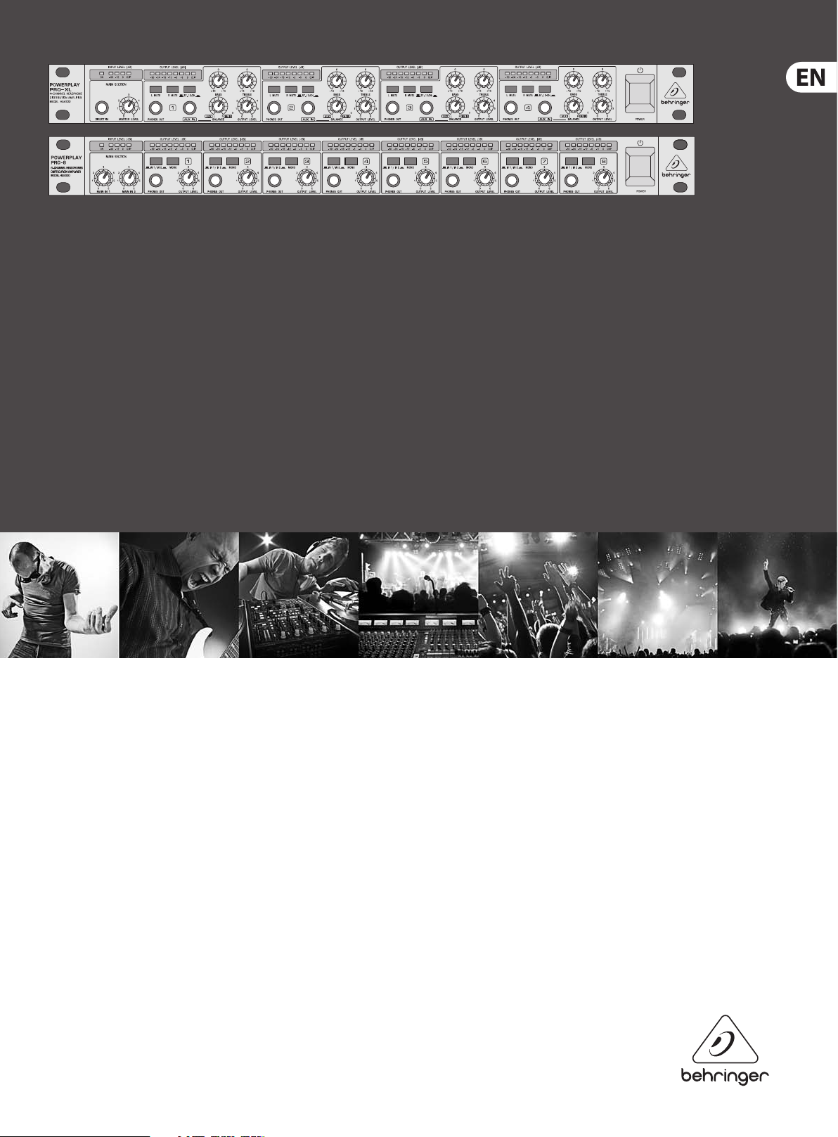
POWERPLAY
PRO-8 HA8000/PRO-XL HA4700
8/4-Channel High-Power Headphones Mixing and
Distribution Amplier
Page 2

2 POWERPLAY PRO-8 HA8000/POWERPLAY PRO -XL HA4700 User Manual
Table of Contents
Important Safety Instructions ...................................... 3
Legal Disclaimer ............................................................. 3
Limited warranty ............................................................ 3
1. Introduction ............................................................... 4
1.1 Before you get started ............................................................. 4
1.2 Warranty ........................................................................................ 4
1.3 The user's manual .................................................................... 4
2. Control Elements ...................................................... 4
2.1 Front panel ................................................................................... 5
2.2 Rear panel ..................................................................................... 5
3. Application Guidelines ............................................. 6
3.1 Using the MAIN IN connectors ............................................ 6
3.2 AUX IN inputs (HA4700 only) .............................................. 6
3.3 Using the DIRECT IN connector ........................................... 6
3.4 Mono mode ................................................................................ 6
3.5 MUTE function (HA4700 only) ............................................ 6
3.6 Connecting multiple headphones ................................... 6
4. Audio Connections .................................................... 7
5. Specications ............................................................. 8
Page 3
3 POWERPLAY PRO-8 HA8000/POWERPLAY PRO -XL HA4700 User Manual
9. Do not defeat the safety purpose of the polarized
TO BIND MUSICGROUP BY ANY EXPRESS OR IMPLIED
Important Safety Instructions
Terminals marked with this symbol carry
electrical current of su cient magnitude
to constitute risk of electric shock.
Use only high-quality professional speaker cables with
¼" TS or twist-locking plugs pre-installed. Allother
installation or modi cation should be performed only
by quali edpersonnel.
This symbol, wherever it appears,
alertsyou to the presence of uninsulated
dangerous voltage inside the
enclosure-voltage that may be su cient to constitute a
risk ofshock.
This symbol, wherever it appears,
alertsyou to important operating and
maintenance instructions in the
accompanying literature. Please read the manual.
Caution
To reduce the risk of electric shock, donot
remove the top cover (or the rear section).
No user serviceable parts inside. Refer servicing to
quali ed personnel.
Caution
To reduce the risk of re or electric shock,
do not expose this appliance to rain and
moisture. The apparatus shall not be exposed to dripping
or splashing liquids and no objects lled with liquids,
suchas vases, shall be placed on the apparatus.
Caution
These service instructions are for use
by quali ed service personnel only.
Toreduce the risk of electric shock do not perform any
servicing other than that contained in the operation
instructions. Repairs have to be performed by quali ed
servicepersonnel.
or grounding-type plug. A polarized plug has two blades
with one wider than the other. A grounding-type plug
has two blades and a third grounding prong. The wide
blade or the third prong are provided for your safety. Ifthe
provided plug does not t into your outlet, consult an
electrician for replacement of the obsolete outlet.
10. Protect the power cord from being walked on or
pinched particularly at plugs, convenience receptacles,
and the point where they exit from the apparatus.
11. Use only attachments/accessories speci ed by
themanufacturer.
12. Use only with the
cart, stand, tripod, bracket,
or table speci ed by the
manufacturer, orsold with
the apparatus. When a cart
is used, use caution when
moving the cart/apparatus
combination to avoid
injury from tip-over.
13. Unplug this apparatus during lightning storms or
when unused for long periods of time.
14. Refer all servicing to quali ed service personnel.
Servicing is required when the apparatus has been
damaged in any way, such as power supply cord or plug
is damaged, liquid has been spilled or objects have fallen
into the apparatus, the apparatus has been exposed
to rain or moisture, does not operate normally, or has
beendropped.
15. The apparatus shall be connected to a MAINS socket
outlet with a protective earthing connection.
16. Where the MAINS plug or an appliance coupler is
used as the disconnect device, the disconnect device shall
remain readily operable.
UNDERTAKING OR REPRESENTATION. THIS MANUAL
IS COPYRIGHTED. NO PART OF THIS MANUAL MAY
BE REPRODUCED OR TRANSMITTED IN ANY FORM
OR BY ANY MEANS, ELECTRONIC OR MECHANICAL,
INCLUDING PHOTOCOPYING AND RECORDING OF ANY
KIND, FOR ANY PURPOSE, WITHOUT THE EXPRESS
WRITTEN PERMISSION OF MUSICGROUPIPLTD.
ALL RIGHTS RESERVED.
© 2013 MUSICGroupIPLtd.
Trident Chambers, Wickhams Cay, P.O. Box 146,
Road Town, Tortola, British Virgin Islands
LIMITED WARRANTY
For the applicable warranty terms and conditions
and additional information regarding MUSIC Group’s
Limited Warranty, please see complete details online at
www.music-group.com/warranty.
1. Read these instructions.
2. Keep these instructions.
3. Heed all warnings.
4. Follow all instructions.
5. Do not use this apparatus near water.
6. Clean only with dry cloth.
7. Do not block any ventilation openings. Install in
accordance with the manufacturer’s instruc tions.
8. Do not install near any heat sources such as
radiators, heat registers, stoves, or other apparatus
(including ampli ers) that produce heat.
LEGAL DISCLAIMER
TECHNICAL SPECIFICATIONS AND APPEARANCES
ARE SUBJECT TO CHANGE WITHOUT NOTICE AND
ACCURACY IS NOT GUARANTEED. BEHRINGER,
KLARKTEKNIK, MIDAS, BUGERA, AND TURBOSOUND
ARE PART OF THE MUSIC GROUP MUSICGROUP.COM.
ALL TRADEMARKS ARE THE PROPERTY OF THEIR
RESPECTIVE OWNERS. MUSICGROUP ACCEPTS NO
LIABILITY FOR ANY LOSS WHICH MAY BE SUFFERED
BY ANY PERSON WHO RELIES EITHER WHOLLY OR
IN PART UPON ANY DESCRIPTION, PHOTOGRAPH
OR STATEMENT CONTAINED HEREIN. COLORS AND
SPECIFICATIONS MAY VARY FROM ACTUAL PRODUCT.
MUSIC GROUP PRODUCTS ARE SOLD THROUGH
AUTHORIZED FULLFILLERS AND RESELLERS ONLY.
FULLFILLERSAND RESELLERS ARE NOT AGENTS OF
MUSICGROUP AND HAVE ABSOLUTELY NO AUTHORITY
Page 4

4 POWERPLAY PRO-8 HA8000/POWERPLAY PRO -XL HA4700 User Manual
1. Introduction
Congratulations! With the BEHRINGER POWERPLAY PRO, you have acquired a highend headphone amplier. Both POWERPLAY PRO units were developed with the most
demanding applications in mind: professional recording, radio and television studios,
as well as CD/digital sound production. They were developed as benchmark units
for judging mixdown quality as well as distribution ampliers for exible playback
applications in studio environments.
Balanced inputs and outputs
Both BEHRINGER POWERPLAY PROs feature electronically servo-balanced inputs
and outputs. The servo function automatically recognizes when unbalanced pins
are assigned. It internally modies the nominal signal level, thus preventing any
occurence of signal level dierence between inputs and outputs (6 dB correction).
◊ The following user's manual is intended to familiarize you with the
unit's control elements, so that you can master all the functions. After
having thoroughly read the user's manual, store it at a safe place for
future reference.
1.1 Before you get started
The POWERPLAY PRO was carefully packed at the assembly plant to assure secure
transport. Should the condition of the cardboard box suggest that damage may have
taken place, please inspect the unit immediately and look for physical indications
ofdamage.
◊ Damaged units should NEVER be sent directly to us. Please inform the
dealer from whom you acquired the unit immediately as well as the
transportation company from which you took delivery of the unit.
Otherwise, all claims for replacement/repair may be rendered invalid.
1.1.1 Initial operation
1.2 Warranty
Please take a few minutes and send us the completely lled out warranty card within
14 days of the date of purchase. You may also register online at www.behringer.com.
The serial number needed for the registration is located at the top of the unit.
Failure to register your product may void future warranty claims.
1.3 The user's manual
This user's manual has been written in such a way to enable you an overview over
the control elements of the unit and oers at the same time detailed information
about possible applications. To facilitate quick look-ups, control elements have
been described in groups depending on their function. Should you need detailed
information about specic topics not covered in this manual, please visit our website
at www.behringer.com. For example, additional information about power amps and
eects processors is found there.
ATTENTION!
◊ We would like to bring your attention to the fact that extremely loud sound
levels may damage your hearing as well as your headphones. Please lower
all OUTPUT LEVEL knobs leftwards before powering up the unit.
2. Control Elements
This chapter contains descriptions of various control elements of your POWERPLAY
PRO. All controls and connections are discussed in detail. Additionally, useful advice
about their possible applications is also given.
The HA8000 has eight independent ampliers for connecting headphones, while the
HA4700 has four. The latter has several additional features not found in the HA8000
due to space considerations. The dierences between the two units are explained in
detail in the text sections that follow.
Please make sure the unit is provided with sucient ventilation, and never place the
POWERPLAY PRO on top of an amplier or in the vicinity of a heater to avoid the risk
of overheating.
◊ Before plugging the unit into a power socket, please make sure you have
selected the correct voltage:
The fuse compartment near the power plug socket contains three triangular markings.
Two of these triangles are opposite one another. The voltage indicated adjacent to
these markings is the voltage to which your unit has been set up, and can be altered
by rotating the fuse compartment by 180°. ATTENTION: This does not apply to export
models that were for example manufactured only for use with 120 V!
◊ If you alter the unit's voltage, you must change the fuses accordingly.
The correct value of the fuses needed can be found in the chapter
"TECHNICAL DATA".
◊ Faulty fuses must be replaced with fuses of appropriate rating without
exception! The correct value of the fuses needed can be found in the
chapter "TECHNICAL DATA".
Power is delivered via the cable enclosed with the unit. All requiered safety
precautions have been adhered to.
◊ Please make sure that the unit is grounded at all times. For your own
protection, you should never tamper with the grounding of the cable or the
unit itself.
(3) (3)
HA4700
HA8000
(1) (2) (2)
Fig. 2.1: Input section
(1) The DIRECT IN socket is used to feed in additional stereo signals. In the case of
the HA4700, the signal brought in via the DIRECT IN input has the same priority
as the MAIN signal. The HA8000 has a separate DIRECT INPUT connector for each
channel (19) (see g. 2.3). In the case of this model, the MAIN signal being fed in is
automatically interrupted when the said input is in use.
(2) The MASTER LEVEL control governs the level of the input signal that
is fed through the MAIN INPUT connectors on the back or through the
DIRECTINconnector.
The HA8000 features two level controls (MAIN IN 1 / MAIN IN 2), so that two
separately controllable input signals can be connected. You select which of the
two signals is monitored by using the IN 1 / IN 2 switches (14) in the respective
channel sections.
Page 5

5 POWERPLAY PRO-8 HA8000/POWERPLAY PRO -XL HA4700 User Manual
(3) The 4-digit INPUT LEVEL display informs you about the input level signal and
diplays it in the range between -30 and 0 dB. When the unit is powered on, the
ON LED lights up. You achive the best input signal quality when its level is at
the highest level just before it starts distorting. The clip LED should light up only
during the highest signal peaks.
2.1 Front panel
(4) (5) (6)
HA4700
(7)
(9) (11)
(8)
(10)
(12)
(13)
(4)
(14)
HA8000
(15)
Fig. 2.2: Individual headphones amplier sections
(4) The 8-digit OUTPUT LEVEL display informs you about the ouput signal level
of each individual channel, and diplays it in the range between -30 and 0 dB.
When the clip LED lights up, lower the amount of gain applied to the individual
channels to avoid distortion.
(5) The BASS control (HA4700 only) attenuates or boosts the low frequency portions
of the signal (+/-12 dB).
The HA8000 does not feature a BALANCE control.
(12) Headphones volume of the individual amp sections is regulated using
the OUTPUT LEVEL control. Both the left and the right channel are
regulatedsimultaneously.
(13) The POWER switch powers the POWERPLAY PRO on. You should always make
sure that the POWER switch is in the "O" position when initially connecting the
unit to the mains.
◊ Please take note: Merely switching the unit off does not mean that it is
fully disconnected from the mains. When not using the unit for prolonged
periods of time, please unplug the unit's power cord from the power outlet.
(14) The MAIN IN 1 or MAIN IN 2 input signal is selected by using the IN 1/ IN 2 switch.
When the DIRECT INPUT of the channel has a signal assigned to it, you can hear
the said signal only (HA8000 only).
(15) When you depress the MONO switch (HA8000 only), the signal is played in mono.
Singers in particular appreciate this function because a mono signal is much less
distracting to listen to than a comparable stereo signal. A mono signal makes
spacial orientation during live performances easier.
2.2 Rear panel
(16) Power is supplied via an IEC connector. The matching cable is provided with
theunit.
(17) FUSE COMPARTMENT 1 VOLTAGE SELECTION. Before connecting the unit to a
power outlet, please make sure that the selected voltage matches your local
voltage. When replacing fuses, please make sure that you always use fuses of
the same type. Some units allow for switching between 230 V und 120 V. Please
note: when connecting a unit intended for the European market to a 120 V power
outlet, you must also replace the factory fuse with a higher-value fuse.
(18) The HEADPHONE OUT connectors of the individual amp sections are also used for
connecting headphones (HA8000: PHONES OUTPUT). The HA4700 features two
additional headphones connectors per channel located on the rear; the HA8000
has one.
(6) The TREBLE control (HA4700 only) attenuates or boosts the high frequency
portion of the signal (+/-12 dB).
(7) The L MUTE and R MUTE switches allow you to mute the respective input signal,
so that only the remaining input signal is audible (HA4700 only).
(8) The PHONES OUT connector is connected in parallel to the output connectors (18)
located on the rear, presenting an easily accessible additional monitor option
for individual channels. This function is particularly helpful when the unit is
permanently installed in a rack.
(9) The AUX IN input is used to mix an additional input signal into the MAIN IN
or DIRECT IN connectors (HA4700 only). Should you want to use this option
on a mono signal, we recommend using the ST./2-CH. switch (position 2-CH,
depressed) in order to hear the signal in both ears.
(10) The ST.12-CH. switch is used to alternate whether input signals are audible in
stereo (not depressed: ST.) or in mono (depressed: 2-CH.) The HA8000 features a
MONO switch instead of a ST./2-CH. switch (15)
(11) The BALANCE control (HA4700 only) regulates the stereo image of input signals,
provided that the AUX IN input of one of the amp sections is not already in use.
When the AUX IN section already has a signal assigned to it, the BALANCE control
governs the ratio between MAIN IN (DIRECT IN) and AUX IN signal.
HA4700
(17)(16) (18) (19)
HA8000
Fig. 2.3: Mains supply, fuses compartment and headphone outputs
(19) Various input signals can be connected to the HA8000 by utilizing a separate
DIRECT IN connection for each amp section, located on the rear. If a signal is fed
into this connector, both MAIN IN signals will be muted.
(20) These are the MAIN OUT connectors of the HA4700. The respective jacks and
XLR connectors are wired in parallel. Via these connectors, you can link as many
headphone amps as desired to allow for connection of additional headphones.
The HA8000 has no MAIN OUT connectors. To connect additional units on a perneed basis, you can use HA8000's PHONES OUTPUT connectors.
Page 6

6 POWERPLAY PRO-8 HA8000/POWERPLAY PRO -XL HA4700 User Manual
In addition to the usage of all channels via the MAIN input, each of the four ampliers
can also be used fully independently. To this end, you may also use the AUX IN inputs
in conjunction with the BALANCE controls. When the BALANCE control is turned to
the left ("AUX" position), the MAIN signal is faded out, and the AUX IN signals are fed
into their respective ampliers. Using individual ampliers separately lets you provide
HA4700
individual mixes to up to four musicians.
(20) (21)
Aux sends / subgroup outputs
HA8000
(22)
Fig. 2.4: MAIN IN and MAIN OUT connectors
(21) The MAIN IN connectors of the HA4700 come as balanced ¼" TRS and
XLRconnectors.
(22) The HA8000 features only ¼" TRS connectors for MAIN INPUT 1 and
MAININPUT2.
3. Application Guidelines
3.1 Using the MAIN IN connectors
Connect a program source with the MAIN IN connectors located on the rear, and
connect your headphones to an amp section of your choice. Set the MASTER LEVEL
and BALANCE controls (HA4700) in the center position. The MASTER LEVEL control is
used to lower or raise the volume level of all headphones which receive signals via
the MAIN IN inputs and/or the DIRECT IN input. In the case of the HA8000, MAIN IN
controls 1 and 2 regulate the input level of two separate input signals. The individual
OUTPUT LEVEL controls are used for adjusting the desired channel volume only.
3.2 AUX IN inputs (HA4700 only)
As a general rule, the AUX IN inputs are used to add an extra input signal to the main
signal, whereby the respective BALANCE control regulates the relative ratio of those
signals to one another.
This way, you can for example eortlessly record vocals and feed in an already existing
playback using your POWERPLAY PRO-XL HA4700. The playback signal is fed through
the MAIN IN inputs, and the preamplied vocal signal is fed into the AUX IN connector.
The respective BALANCE control should be set up in such a way that the singer gets a
perfectly matched mix between the playback and the vocals, whereby the OUTPUT
LEVEL control regulates the overall volume.
1 2 3 4
X1832USB
mixing console
Fig. 3.2: Monitor live application
OUT 1
AUX IN 1
OUT 2 OUT 3 OUT 4
AUX IN 2
AUX IN 3
AUX IN 4
3.3 Using the DIRECT IN connector
The DIRECT IN connector (HA4700) is located on the left side of the front section.
For example, you can use this connector to provide musicians with the signal of a
DAT recorder or CD player. The HA8000 has a separate DIRECT IN connector for each
amplier (located on the rear). In the case of the HA8000, allocating a signal to this
connector mutes the MAIN IN signal. The input level must be externally set in this
case. This way, you can use each amplier section for a separate headphone signal.
3.4 Mono mode
Stereo signals can often have an irritating eect in certain monitoring applications,
especially when performing live. These negative eects are particularly apparent
when both channels show great channel separation, i.e. a dierent information
content coupled with varying volume levels. The ST./2-CH. switch (HA8000: the
MONOswitch) allows coupling the left and the right channels into a single mono
signal, withouth needing a "Y"-adapter or a special cable.
3.5 MUTE function (HA4700 only)
When the ST./2-CH. switch is depressed, the unit is running mono. By depressing
either one of the MUTE switches, the respective input's signal (i.e. either the left or
the right input) is muted, while the signal not being muted can be heard on BOTH
(leftand right) headphone outputs. This allows you to feed two dierent program
sources yet be able to listen to only one of them on a per-need basis.
Channel 1
MIC INLINE
OUT
X1832USB
mixing console
Fig. 3.1: Playback application in a studio
MAIN
IN
OUT
HEADPHONE OUT 1
AUX IN 1
3.6 Connecting multiple headphones
The HA4700 features three headphones connectors altogether, while the HA8000 has
two. You can connect multiple headphones to an amp simultaneously, provided that
the minimal output load impedance of the amp does not fall below 8 Ohms. In the
case of the HA8000, the minimal output load impedance is 100 Ohms per amp.
◊ When connecting two headphones, individual headphones should
not have impedance lower than 16 Ohms; when connecting three
headphones, individual headphones should not have impedance lower
than 24 Ohms (HA4700). When connecting two headphones to the HA8000,
the impedance of individual headphones should not fall below 200 Ohms.
Even though going under the above mentioned minimal impedances does not
cause deective operation, you may experience a quality loss audible as lowered
performance and distortion.
Page 7

7 POWERPLAY PRO-8 HA8000/POWERPLAY PRO -XL HA4700 User Manual
4. Audio Connections
Balanced use with XLR connectors
12
3
input
1 = ground/shield
2 = hot (+ve)
3 = cold (-ve)
1
2
3
output
For unbalanced use, pin 1 and pin 3
have to be bridged
Fig. 4.1: XLR connector
Unbalanced ¼" TS connector
strain relief clamp
sleeve
tip
Balanced ¼" TRS connector
strain relief clamp
sleeve
ring
tip
sleeve
ground/shield
ring
cold (-ve)
tip
hot (+ve)
For connection of balanced and unbalanced plugs,
ring and sleeve have to be bridged at the stereo plug.
Fig. 4.3: ¼" TRS connector
¼" TRS headphones connector
strain relief clamp
sleeve
ring
tip
Fig. 4.2: ¼" TS connector
sleeve
(ground/shield)
tip
(signal)
sleeve
ground/shield
ring
right signal
tip
left signal
Fig. 4.4: ¼" TRS connector for headphones operation
◊ Please assure that the unit is installed and operated only by people with
an understanding of the unit's functions. During and after the installation
always make sure that those handling the unit are themselves properly
grounded. Failure to do so may cause undesirable or faulty operation
through electrostatic discharge.
Page 8

8 POWERPLAY PRO-8 HA8000/POWERPLAY PRO -XL HA4700 User Manual
5. Specications
POWERPLAY PRO-8 HA8000
Audio Inputs
MAIN IN HFltered servobalanced
¼"TRSconnectors
Input impedance 40 k balanced, 20 k unbalanced
Max. input level 16 dBu balanced and unbalanced
CMRR typically 40 dB, >55 dB @ 1 kHz
AUX IN
Input impedance
Max input level
DIRECT IN ¼" TRS connector (stereo)
Input impedance 15 k
Audio Outputs
MAIN OUT
PHONES OUTPUT ¼" TRS connector (stereo)
Power Amplier
Max. output power +24 dBm (load impedance 100 )
Min. output load impedance 100 kΩ
System Specications
Frequency response 10 Hz to 150 kHz, +/-3 dB
Noise 22 Hz to 22 kHz >90 dB @ 0 dBu
Function Switches
Stereo/2-Channel
Main in 1 / Main in 2 switches between MAIN Input 1 and
MAIN Input 2
Left mute
Right mute
Mono switches this section to mono
Displays
Input Level 4-digit LED-display: -30/-12/0 dB/CLIP
Output Level 8-digit LED-display:
-30/-24/-18/-12/-6/-3/0 dB/CLIP
Power Supply
Mains voltage
USA/Canada 120 V~, 60 Hz
U.K./Australia 230 V~, 50 Hz
Japan 100 V~, 50 - 60 Hz
General export model 120/230 V~, 50 - 60 Hz
Power consumption 30 W
Fuses 100 - 120 V ~: T630 mA H,
220 - 240 V~: T 315 mA H
Mains connection Standard IEC receptacle
Dynamic range 22 Hz to 22 kHz: 110 dB
Distortion (THD) 0.006 % typ. @ +4 dBu, 1 kHz, Gain 1
Function Controls
Input level variable
Balance per channel
Output level per channel variable
Treble
Bass
Dimensions/Weight
Dimensions (H x D x W) approx. 44.5 x 483 x 217 mm
approx. (1.75 x 19 x 8.5")
Weight approx. 2.6 kg (5.7 lbs)
Page 9

9 POWERPLAY PRO-8 HA8000/POWERPLAY PRO -XL HA4700 User Manual
POWERPLAY PRO-XL HA4700
Audio Inputs
MAIN IN HFltered servobalanced XLR and
¼" TRS connectors
Input impedance 40 k balanced, 30 k unbalanced
Max. input level 16 dBu balanced and unbalanced
CMRR typically 40 dB, >55 dB @ 1 kHz
AUX IN ¼" TRS connector (stereo)
Input impedance 5 k
Max input level +22 dBu
DIRECT IN ¼" TRS connector (stereo)
Input impedance 15 k
Audio Outputs
MAIN OUT XLR and ¼" TRS connectors, balanced
PHONES OUTPUT ¼" TRS connector (stereo)
Power Amplier
Max. output power +24 dBm (load impedance 100 ),
+21 dBm (load impedance 8 )
Min. output load impedance 8 kΩ
Function Switches
Stereo/2-Channel switches between stereo mode and
2-channel mode
Main in 1 / Main in 2
Left mute mutes the left signal of the respective
channel
Right mute mutes the right signal of the respective
channel
Mono
Displays
Input Level 4-digit LED-display: -30/-12/0 dB/CLIP
Output Level 8-digit LED-display:
-30/-24/-18/-12/-6/-3/0 dB/CLIP
Power Supply
Mains voltage
USA/Canada 120 V~, 60 Hz
U.K./Australia 230 V~, 50 Hz
Japan 100 V~, 50 - 60 Hz
General export model 120/230 V~, 50 - 60 Hz
System Specications
Frequency response 10 Hz to 150 kHz, +/-3 dB
Noise 22 Hz to 22 kHz >90 dB @ 0 dBu
Dynamic range 22 Hz to 22 kHz: 110 dB
Distortion (THD) 0.006 % typ. @ +4 dBu, 1 kHz, Gain 1
Function Controls
Input level variable
Balance per channel mix between Aux and Main signals /
balance between right and left channel
Output level per channel variable
Treble cutof f frequency: 6 kHz;
range +/- 12 dB
Bass cutoff frequency: 200 Hz,
range +/- 12 dB
Power consumption 34 W
Fuses 100 - 120 V ~: T630 mA H,
220 - 240 V~: T315 mA H
Mains connection Standard IEC receptacle
Dimensions/Weight
Dimensions (H x D x W) approx. 44.5 x 483 x 217 mm
approx. (1.75 x 19 x 8.5")
Weight approx. 2.5 kg (5.5 lbs)
BEHRINGER i s constantly str iving to maintain the h ighest profess ional standards. A s a result of these e ffort s,
modific ations may be made f rom time to time to exi sting product s without prio r notice. Specif ications and
appearance m ay differ fro m those listed or illus trated.
Page 10

We Hear You
 Loading...