


PMP3000

User Manual
Version 1.0 November 2006
PMP1000/PMP3000/PMP5000
EUROPOWER
EUROPOWER PMP1000/PMP3000/PMP5000
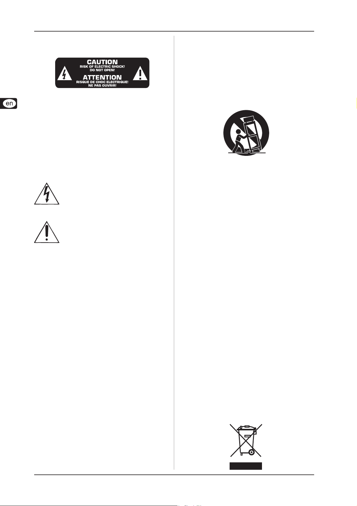
IMPORTANT SAFETY INSTRUCTIONS
CAUTION: To reduce the risk of electric shock, do not remove
the top cover (or the rear section). No user
serviceable parts inside; refer servicing to qualified
personnel.
WARNING: To reduce the risk of fire or electric shock, do not
expose this appliance to rain and moisture. The
apparatus shall not be exposed to dripping or
splashing and no objects filled with liquids, such
as vases, shall be placed on the apparatus.
This symbol, wherever it appears, alerts you to the
presence of uninsulated dangerous voltage inside
the enclosure—voltage that may be sufficient to
constitute a risk of shock.
This symbol, wherever it appears, alerts you to
important operating and maintenance instructions
in the accompanying literature. Please read the
manual.
12) Where the MAINS plug or an appliance coupler is
used as the disconnect device, the disconnect device
shall remain readily operable.
13) Only use attachments/accessories specified by the
manufacturer.
14) Use only with the cart, stand, tripod, bracket, or table
specified by the manufacturer, or sold with the
apparatus. When a cart is used, use caution when moving
the cart/apparatus combination to avoid injury from
tip-over.
15) Unplug this apparatus during lightning storms or
when unused for long periods of time.
16) Refer all servicing to qualified service personnel.
Servicing is required when the apparatus has been
damaged in any way, such as power supply cord or plug
is damaged, liquid has been spilled or objects have fallen
into the apparatus, the apparatus has been exposed to
rain or moisture, does not operate normally, or has been
dropped.
17) CAUTION - These service instructions are for use by
qualified service personnel only. To reduce the risk of
electric shock do not perform any servicing other than
that contained in the operation instructions unless you
are qualified to do so.
1) Read these instructions.
2) Keep these instructions.
3) Heed all warnings.
4) Follow all instructions.
5) Do not use this apparatus near water.
6) Clean only with dry cloth.
7) Do not block any ventilation openings. Install in
accordance with the manufacturer’s instructions.
8) Do not install near any heat sources such as radiators,
heat registers, stoves, or other apparatus (including
amplifiers) that produce heat.
9) Do not defeat the safety purpose of the polarized or
grounding-type plug. A polarized plug has two blades
with one wider than the other. A grounding type plug
has two blades and a third grounding prong. The wide
blade or the third prong are provided for your safety. If
the provided plug does not fit into your outlet, consult
an electrician for replacement of the obsolete outlet.
10) Protect the power cord from being walked on or
pinched particularly at plugs, convenience receptacles,
and the point where they exit from the apparatus.
11) The apparatus shall be connected to a MAINS socket
outlet with a protective earthing connection.
2

EUROPOWER PMP1000/PMP3000/PMP5000
FOREWORD
Dear Customer,
Welcome to the team of
EUROPOWER users
and thank you very much
for expressing your confidence in BEHRINGER
products by purchasing
this power mixer.
It is one of my most
pleasant tasks to write
this letter to you, because
it is the culmination of
many months of hard
work delivered by our
engineering team to reach
a very ambitious goal:
to present you three
outstanding power
mixers that give you
maximum flexibility and
performance with a unique sound character and broad range of
striking functions. The task to design the new PMP series certainly
meant a great deal of responsibility, which we assumed by
focusing on you, the discerning user and musician. It also meant
a lot of work and night shifts to accomplish this goal. But it was
fun, too. Developing a product usually brings a lot of people
together, and what a great feeling it is when everybody who
participated in such a project can be proud of what we’ve
achieved.
It is our philosophy to share our joy with you, because you
are the most important member of the BEHRINGER team. With
your highly competent suggestions for new products you’ve
greatly contributed to shaping our company and making it
successful. In return, we guarantee you uncompromising quality
as well as excellent technical and audio properties at an extremely
favorable price. All of this will enable you to fully unfold your
creativity without being hampered by budget constraints.
We are often asked how we can make it to produce such highgrade devices at such unbelievably low prices. The answer is
quite simple: it’s you, our customers! Many satisfied customers
means large sales volumes enabling us to get better conditions
of purchase for components, etc. Isn’t it only fair to pass this
benefit back to you? Because we know that your success is our
success, too!
I would like to thank all people whose help on “Project PMP”
has made it all possible. Everybody has made very personal
contributions, starting from the designers of the unit to the many
staff members in our company and finally to you, the user of
BEHRINGER products.
TABLE OF CONTENTS
1 INTRODUCTION .........................................................4
1.1 Before you get started................................................... 4
1.1.1 Shipment............................................................... 4
1.1.2 Initial operation...................................................... 4
1.1.3 Online registration ................................................ 4
1.2 The manual ..................................................................... 4
2 CONTROL ELEMENTS ............................................... 5
2.1 Mono and stereo channels ............................................ 5
2.1.1 Input section ......................................................... 5
2.2 Equalizer and FBQ.......................................................... 6
2.3 Effects section ............................................................... 7
2.4 Main and monitor section................................................ 7
2.4.1 Connectors........................................................... 8
2.5 Rear panel ...................................................................... 8
3 DIGIT AL EFFECTS PROCESSOR ................................ 8
4 INST ALLATION...........................................................9
4.1 Mains connection ........................................................... 9
4.2 Audio connections ......................................................... 9
4.3 Loudspeaker connections ........................................... 10
5 WIRING EXAMPLES ................................................. 11
6 SPECIFICATIONS .....................................................14
7 WARRANTY.............................................................. 16
FCC— FEDERAL COMMUNICA TIONS COMMISSION
COMPLIANCE INFORMA TION .................................. 17
My friends, it’s been worth the trouble!
Thank you very much,
Uli Behringer
CAUTION!
We would like to point out that high volume levels may
damage your hearing and/or your headphones. Please
move down all faders in the MAIN section before turning
on the device. Always make sure that the
volume is set.
appropriate
3

EUROPOWER PMP1000/PMP3000/PMP5000
1 INTRODUCTION
Congratulations! With the PMP1000/PMP3000/PMP5000 you
have acquired a state-of-the-art power mixer that sets new
standards. Right from the very start it has been our goal to
design a revolutionary unit that can be used for a wide variety of
applications. Indeed, this overwhelming power mixer gives you
plenty of functionality and a broad range of connection and
expansion options.
Your PMP features our revolutionary COOLAUDIO amplifier
technology, which reduces the weight and size of the unit
considerably and ensures extremely high output power.
Further advantages are the integrated Voice Canceller that
removes vocal passages from playbacks, the FBQ function,
which detects feedback frequencies, and the Speaker
Processing function for loudspeaker alignment—all with a
resolution of 24 bits and 40 kHz. Plus, our tried and tested
XENYX Mic Preamps give you crystal-clear audio free of noise
and distortion when using microphones.
BEHRINGER is a company with its roots in professional
recording studio technology. For many years we have been
successful in developing products for studio and live use. These
include microphones and 19" units of all types (compressors,
enhancers, noise gates, tube processors, headphone amplifiers,
digital effects, DI boxes, etc.), monitor and P.A. speakers and
professional live and recording mixers. Our entire technical knowhow has gone into your PMP power mixer.
1.1 Before you get started
1.1.1 Shipment
Your PMP was carefully packed at the factory and the
packaging is designed to protect the unit from rough handling.
Nevertheless, we recommend that you carefully examine the
packaging and its contents for any signs of physical damage
which may have occurred during transit.
If the unit is damaged, please do NOT return it to
BEHRINGER, but notify your dealer and the shipping
company immediately. Otherwise, claims for
damage or replacement may not be granted.
We recommend that you use a flight case, so as to
give your power mixer optimum protection during
use or transport.
Always use the original packing carton to prevent
damage during storage or transport.
1.1.2 Initial operation
Be sure that there is enough air space around the unit for
cooling and, to avoid overheating, please do not place the
EUROPOWER near radiators, etc.
Blown fuses must be replaced by fuses of the same
type and rating! Please refer to the
“SPECIFICATIONS” for details.
The mains connection is made using the enclosed power cord
and a standard IEC receptacle. It meets all of the international
safety certification requirements.
Please make sure that all units have a proper
ground connection. For your own safety, never
remove or disable the ground conductor from the
unit or on the AC power cord.
To avoid damage on the device, do not
- earth the loudspeaker outputs
- connect the loudspeaker outputs to each other
- connect the loudspeaker outputs to those of other
amplifiers
IMPORTANT NOTES CONCERNING INSTALLATION
The sound quality may diminish within the range of powerful
broadcasting stations and high-frequency sources. Increase
the distance between the transmitter and the device and use
shielded cables for all connections.
1.1.3 Online registration
Please do remember to register your new BEHRINGER
equipment right after your purchase by visiting
www.behringer.com (alternatively www.behringer.de) and
kindly read the terms and conditions of our warranty carefully.
Should your BEHRINGER product malfunction, our goal is to
have it repaired as quickly as possible. To arrange for warranty
service, please contact the retailer from whom the equipment
was purchased. Should your BEHRINGER dealer not be located
in your vicinity, you may directly contact one of our subsidiaries.
Corresponding contact information is included in the original
equipment packaging (Global Contact Information/European
Contact Information). Should your country not be listed, please
contact the distributor nearest you. A list of distributors can be
found in the support area of our website (www.behringer.com).
Registering your purchase and equipment with us helps us
process your repair claims quicker and more efficiently.
Thank you for your cooperation!
Make sure that children cannot play unsupervised
with the device or its packaging.
Please ensure proper disposal of all packing
materials.
4
1 INTRODUCTION
1.2 The manual
This manual is designed to give you both an overview of all
control elements and to provide details about how to use them.
To provide you with a clear structure, we have grouped the
control elements according to their function. They can easily be
found on the enclosed numbered illustrations. If you need more
detailed information on specific topics, please visit our web site
at www.behringer.com.

EUROPOWER PMP1000/PMP3000/PMP5000
2 CONTROL ELEMENTS
A detailed description of all functions of your power mixer can
be found in the following chapters. Please also refer to the
enclosed sheet with the numbered illustrations to get a good
overview of the control layout.
2.1 Mono and stereo channels
Use the TRIM control to adjust the input gain. Be sure to
set this control fully counter-clockwise before you connect
or disconnect a signal source to an input. TRIM controls
both the microphone and the LINE input. The black scale
shows the microphone gain (+10 to +60 dB on channels
with XENYX MIC PREAMPS and 0 to +40 dB on conventional
microphone inputs;
The “LINE” scale indicates the sensitivity of the LINE input,
ranging from +10 to -40 dBu.
PMP1000: The mono/stereo combination channels 5/6 and
7/8 have a sensitivity of +20 to -20 dBu.
The LEVEL SET LED illuminates when an optimum operating
level has been adjusted.
The mono channels are equipped with a high-slope LOW
CUT filter eliminating unwanted low-frequency signals like
rumble noise.
PMP3000/PMP5000 (stereo channels): Press the A/B button
to switch from 1/4" jacks to RCA connectors, and vice
versa. Position “A” = 1/4" jacks; position “B” = RCA
connectors.
The HIGH control in the EQ section governs the high
frequency range of the respective channel.
Use the MID control to boost or cut the midrange
frequencies.
PMP5000: The PMP5000 has an additional semi-parametric
filter for the midrange frequencies in the mono channels
(tunable from 100 Hz to 8 kHz). Adjust the boost/cut with
the MID control, and the frequency with the FREQ control.
The stereo channels contain a stereo EQ section. The cutoff frequencies of the high and low bands are 12 kHz and
80 Hz respectively, while the center frequencies of the
high-mid and low-mid bands are 3 kHz and 400 Hz
respectively.
The LOW control allows you to boost/cut the low frequency
range.
With the MON(ITOR) control you can adjust the volume of
each channel in the monitor mix.
The PMP3000 and PMP5000 feature a second MON control
(MON 2) for the volume of the second monitor bus.
The FX control determines the signal level sent from each
channel to the built-in effects processor; this signal is also
present at the FX SEND jack (see
The PMP5000 has two FX controls (FX 1 and FX 2), so that
you can use two effects simultaneously. Accordingly, the
PMP5000 also has two effect aux buses, which have one
output jack in common (see
PMP1000 only, channels 5/6 and 7/8).
).
and ).
Please note that the effects processor signal will
be inaudible, as long as the FX TO MON/MAIN
controls
clockwise.
The PAN(ORAMA) control determines the position of the
channel signal in the stereo main mix.
The BAL(ANCE) control for the stereo channels
corresponds to the PAN control for the mono channels. It
determines the relative volume of the left and right input
signals before they are routed to the stereo main output.
, , are set fully counter-
PMP3000/PMP5000: When you press the PFL button (Pre
Fader Listening) the left LED
input gain of the channel. Adjust the optimum input gain (0
dB) with the TRIM control
ponding LED illuminates.
If the LEVEL SET LED
signal is within the optimum operating level range. However,
if the CLIP LED indicates that the input gain is too high, you
should reduce the level slightly with the TRIM control. The
CLIP LED should never be illuminated all the time, only with
signal peaks.
The MUTE switch mutes the channel in the main mix. The
pre-fader signals (monitor buses) remain operative. When
MUTE is pressed, the corresponding control LED illuminates.
The channel fader controls the channel signal level in the
main mix.
shows the pre-fader
. When PFL is on, the corres-
is illuminated constantly, the
2.1.1 Input section
Each mono input channel is equipped with a balanced
microphone input (XLR connector) which provides
+48 V phantom power for condenser microphones at the
touch of a button (see rear panel).
PMP1000: The two stereo channels 5/6 and 7/8 have an
additional balanced XLR microphone input with +48 V
phantom power.
Be sure to switch off your audio system before you
activate the phantom power supply to protect your
monitor speakers from switch-on thumps.
Each mono input features one LINE IN connector
(1/4" jack), which can be used with either balanced or
unbalanced signals.
Please remember to use either the microphone or
the line input on a specific channel. Never use both
at the same time!
When you connect a mono line signal to a stereo
channel, always use the left input. The mono signal
will then be reproduced by both sides equally.
PMP1000: This does not apply to the mono/stereo
combination channels 5/6 and 7/8.
INSERT I/O. Insert points or simply inserts are used to
process a signal with dynamic processors or equalizers.
They are pre-fader, pre-EQ and pre-MON/FX SEND. Unlike
reverb and other effects, which are usually added to the
dry signal, dynamic processors usually process the entire
signal. So, aux send buses are not the best solution.
Dynamic processors need to be inserted directly into the
signal path. Once processed, the signal then returns to the
mixing console at the same point where it left. Signal
interruption takes place only if a plug is inserted into the
corresponding jack (1/4" stereo plug: tip = signal output,
ring = input). All mono input channels are equipped with
inserts.
The stereo channels have a TRIM control for gain
adjustment, with the input sensitivity ranging from +20 to
-20 dB.
PMP1000: The stereo channels 5/6 and 7/8 feature an
additional XLR connector for microphones whose gain
can be set from 0 to +40 dB.
Each stereo channel has two line-level inputs (1/4" jacks)
for the left and right channels. If only the jack marked “L” is
used, the channel is mono. The signal will then be
reproduced on both sides.
PMP1000: This does not apply to the mono/stereo
combination channels 5/6 and 7/8.
2 CONTROL ELEMENTS
5

EUROPOWER PMP1000/PMP3000/PMP5000
PMP1000: Channels 13/14 and 15/16 are routed to
the main mix without additional tone or volume
adjustment. For example, using the channels 13/14
and 15/16 you can connect a submixer and utilize
the PMP1000’s power amplifier.
PMP3000: The stereo channels 9/10 and 11/12 are equipped
with additional RCA connectors.
PMP5000: The stereo channels 13/14 and 15/16 are
equipped with additional RCA connectors.
PMP3000/PMP5000: Please note that you need to set
the A/B selector
connect a signal to the input.
PMP3000/PMP5000: Each of the two stereo channels has
two monitor controls (MON 1/2) and a LEVEL control
Like the other channels, they also feature a PFL switch.
Instead of a fader this channel has a rotary LEVEL control.
The phantom power supply provides the voltage necessary
for the operation of condenser microphones. Use the
PHANTOM switch to activate the supply for the XLR
connectors of the input channels. The +48 V LED will
illuminate when phantom power is on. In most cases,
dynamic microphones can still be used, as long as they are
connected in a balanced configuration. If in doubt, please
contact the manufacturer of your microphone!
to A (1/4") or B (RCA) when you
With phantom power switched on, you must never
connect microphones to the console (or to a stage/
wall box). Also, be sure to mute the monitor/P.A.
speakers, before you turn on the phantom power
supply. After switching on, please allow the system
to stabilize for about one minute, before you adjust
the input gain.
Caution! Never use unbalanced XLR connectors
(pins 1 and 3 interconnected) on the MIC input jacks,
if you are going to use the phantom power supply.
The AMP MODE switch determines the mode of operation
of the PMP amplifier stage:
PMP1000:
MAIN: In the “MAIN” position the mixer works as a stereo
amplifier.
MON: In this mode the monitor signal is present at OUTPUT
A
and the main signal at OUTPUT B (both are
mono).
BRIDGE (bridged mono mode): In BRIDGE AMP MODE
the output power of OUTPUT A is added to that of OUTPUT
B, i.e. OUTPUT B delivers twice its normal output power.
PMP3000/PMP5000:
MAIN L/MAIN R. In position MAIN MIX, the mixer works as
a stereo amplifier.
MON 1/MONO. In this mode the monitor 1 signal is present
at OUTPUT A
(both are mono).
BRIDGE (bridged mono mode): In BRIDGE AMP MODE
the output power of OUTPUT A is added to that of OUTPUT
B, i.e. OUTPUT B delivers twice its normal output power.
and the main signal at OUTPUT B
In BRIDGE mode, always connect only one
loudspeaker with an impedance of at least
the OUTPUT B jack! Please note that OUTPUT A must
NEVER be used in BRIDGE mode!
8
ΩΩ
Ω to
ΩΩ
In all other operating modes, the minimum
impedance of the speaker must not fall below
4
Please note that the power delivered to the speaker
connected to OUTPUT B in BRIDGE AMP MODE is
considerably higher than the power provided to the
speakers wired to the parallel speaker outputs.
Please read the information given on the rear panel
of the power mixer.
Information on how to properly connect your
speaker with regard to polarity can be found on the
rear of the unit (PIN assignment) (see also
and ).
PMP5000: Use the BEHRINGER SPEAKER PROCESSING
switch to activate a filter that allows you to adapt the mixer
to the characteristics of your loudspeakers. If the speakers
have a limited frequency response in the bass range, this
.
function allows you to filter this range at the output signal
of the mixer and thus adapt it optimally to the frequency
response of the speakers.
PMP1000/PMP5000: If STANDBY is pressed, all input
channels are muted. During pauses you can prevent the
microphones from picking up noise or interference, which
would then be reproduced by the P.A. system or possibly
damage the speaker diaphragms. The benefit is that all
faders can be left untouched while you play back music
from CD via the CD/TAPE inputs (see
no need to move the faders and lose your mix.
). There is also
2.2 Equalizer and FBQ
Your power mixer features a graphic 7-band equalizer,
which allows you to fine-tune the sound depending on the
room acoustics. In the center position the frequency
response is not effected. To boost or cut a certain
frequency range, simply move the corresponding fader
upward or downward respectively.
Please note that the equalizer behaviour depends
on the position of the AMP MODE switch (see
Press the FBQ IN switch to activate the
Feedback Detection system (the FBQ will be
active only if you have switched on the
equalizer
feedback are shown by brightly lit fader
LEDs. All other LEDs will be darker. Now, cut the frequency
range in question until feedback disappears (the LED gets
darker or goes out). This function is available for both the
main and monitor mix.
PMP1000: The switch FBQ FEEDBACK DETECTION
performs the same function as on the PMP3000 and
PMP5000.
Use the MAIN/MON 1 switch to select whether the equalizer
processes the main or the monitor mix. When not pressed,
the stereo equalizer processes only the main mix. When
the switch is pressed, the EQ processes only the monitor
mix.
PMP1000: The MAIN MIX/MONITOR switch performs the
same function as on the PMP3000 and PMP5000.
Press the EQ IN switch to activate the equalizer. The fader
LEDs illuminate when the EQ is on.
Use this LED display to control the output level of the main
signal. The upper LIM LED illuminates when the internal
amp protection circuit responds to levels that are too high.
PMP1000: The POWER LED is illuminated when you switch
the unit on.
before). Frequencies causing
The LIM LEDs and the LED display do NOT light up
when an external signal is fed in via the PWR AMP
ΩΩ
Ω.
ΩΩ
INSERT jacks
.
).
6
2 CONTROL ELEMENTS
 Loading...