

Page 1
EUser´s Manual
Bedienungsanleitung
D
1
Page 2

EG-Declaration of Conformity
acc. to the Directives
89/336/EWG and 73/23/EWG
We, BEHRINGER INTERNATIONAL GmbH
Hanns-Martin-Schleyer-Straße 36-38
D - 47877 Willich
Name and address of the manufacturer or the introducer of the product on the market who is established in the EC
herewith take the sole responsibility to confirm that the product:
MODULIZERPRO DSP1200P
Type designation and, if applicable, Article-N
o
Spezielle Studiotechnik GmbH
which refers to this declaration, is in accordance with the following standards or standardized documents:
x EN 60065 x EN 61000-3-2
x EN 55020 x EN 61000-3-3
x EN 55013 x EN 55022
The following operation conditions and installation arrangements have to be presumed:
acc. to Operating Manual
B. Nier, President Willich, 01.11.1998
Name, address, date and legally binding signature of the person responsible
2
Page 3
SAFETY INSTRUCTIONS
CAUTION: To reduce the risk of electrical shock, do not remove
the cover (or back). No user serviceable parts inside;
refer servicing to qualified personnel.
WARNING: To reduce the risk of fire or electrical shock, do not
expose this appliance to rain or moisture.
This symbol, wherever it appears, alerts
you to the presence of uninsulated
dangerous voltage inside the enclosure
- voltage that may be sufficient to constitute a risk of shock.
DETAILED SAFETY INSTRUCTIONS:
All the safety and operation instructions should be read before the appliance is operated.
Retain Instructions:
The safety and operating instructions should be retained for future reference.
Heed Warnings:
All warnings on the appliance and in the operating instructions should be adhered to.
Follow instructions:
All operation and user instructions should be followed.
Water and Moisture:
The appliance should not be used near water (e.g. near a bathtub, washbowl, kitchen sink, laundry tub, in a wet
basement, or near a swimming pool etc.).
Ventilation:
The appliance should be situated so that its location or position does not interfere with its proper ventilation.
For example, the appliance should not be situated on a bed, sofa rug, or similar surface that may block the
ventilation openings, or placed in a built-in installation, such as a bookcase or cabinet that may impede the
flow of air through the ventilation openings.
Heat:
The appliance should be situated away from heat sources such as radiators, heat registers, stoves, or other
appliance (including amplifiers) that produce heat.
Power Source:
The appliance should be connected to a power supply only of the type described in the operating instructions
or as marked on the appliance.
Grounding or Polarization:
Precautions should be taken so that the grounding or polarization means of an appliance is not defeated.
Power-Cord Protection:
Power supply cords should be routed so that they are not likely to be walked on or pinched by items placed
upon or against them, paying particular attention to cords and plugs, convenience receptacles and the point
where they exit from the appliance.
Cleaning:
The appliance should be cleaned only as recommended by the manufacturer.
Non-use Periods:
The power cord of the appliance should be unplugged from the outlet when left unused for a long period of time.
Object and Liquid Entry:
Care should be taken so that objects do not fall and liquids are not spilled into the enclosure through openings.
Damage Requiring Service:
The appliance should be serviced by qualified service personnel when:
- The power supply cord or the plug has been damaged; or
- Objects have fallen, or liquid has been spilled into the appliance; or
- The appliance has been exposed to rain; or
- The appliance does not appear to operate normally or exhibits a marked change in performance; or
- The appliance has been dropped, or the enclosure damaged.
Servicing:
The user should not attempt to service the appliance beyond that is described in the Operating Instructions. All
other servicing should be referred to qualified service personnel.
This symbol, wherever it appears, alerts
you to important operating and maintenance instructions in the accompanying
literature. Read the manual.
E
3
Page 4

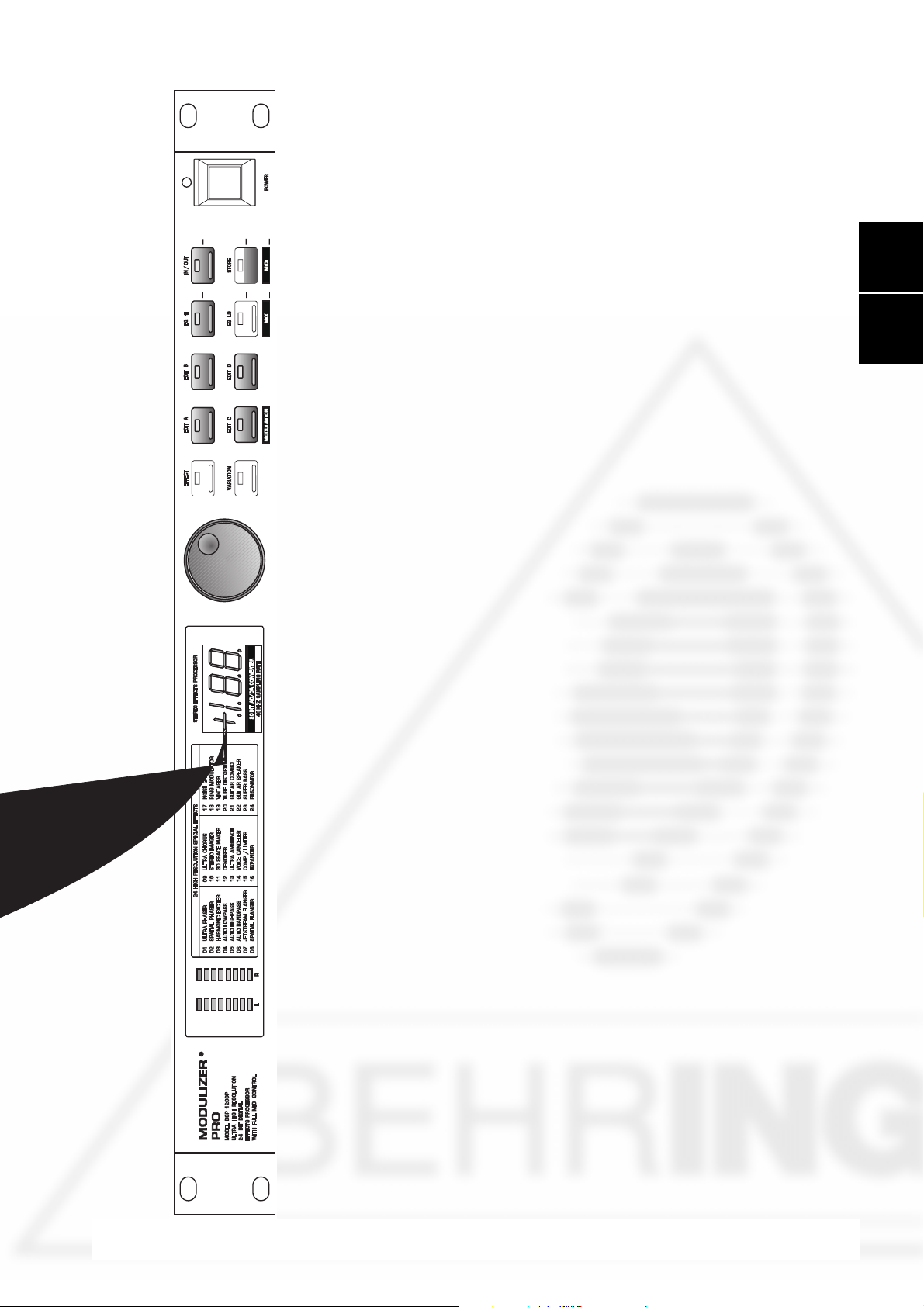
MODULIZERPRO
Ultra-high performance Digital Multi-Effects Processor powered by a 24-bit high-speed Digital Signal Processor (DSP)
DSP1200P
4
Page 5

FOREWORD
Dear Customer,
Welcome to the team of MODULIZERPRO users and thank you very much for expressing your confidence in
BEHRINGER products by purchasing this unit.
It is one of my most pleasant tasks to write this letter to you, because it is the culmination of many months of
hard work delivered by our engineering team to reach a very ambitious goal: making an outstanding device that
will become a standard tool used by studios and P.A. companies. The task to design the MODULIZERPRO
certainly meant a great deal of responsibility, which we assumed by focusing on you, the discerning user and
musician. It also meant a lot of work and night shifts to accomplish this goal. But it was fun, too. Developing a
product usually brings a lot of people together, and what a great feeling it is when everybody who participated
in such a project can be proud of what weve achieved.
It is our philosophy to share our joy with you, because you are the most important member of the BEHRINGER
family. With your highly competent suggestions for new products youve greatly contributed to shaping our
company and making it successful. In return, we guarantee you uncompromising quality (manufactured under
ISO9000 certified management system) as well as excellent technical and audio properties at an extremely
favorable price. All of this will enable you to fully unfold your creativity without being hampered by budget
constraints.
We are often asked how we can make it to produce such high-grade devices at such unbelievably low prices.
The answer is quite simple: its you, our customers! Many satisfied customers means large sales volumes
enabling us to get better conditions of purchase for components, etc. Isnt it only fair to pass this benefit back
to you? Because we know that your success is our success, too!
I would like to thank all people whose help on Project MODULIZERPRO has made it all possible. Everybody
has made very personal contributions, starting from the designers of the unit via the many staff members in our
company to you, the user of BEHRINGER products.
E
My friends, its been worth the trouble!
Thank you very much,
Uli Behringer
5
Page 6

TABLE OF CONTENTS
1. INTRODUCTION..................................................................................................................... 7
1.1 The design concept ......................................................................................................................... 7
1.2 Before you begin ............................................................................................................................. 8
1.3 Control elements............................................................................................................................ 9
1.3.1 Front panel control elements ................................................................................................. 9
1.3.2 Key combinations ............................................................................................................... 10
1.3.3 Back panel .......................................................................................................................... 11
1.4 The effect algorithms ..................................................................................................................... 12
2. OPERATION .......................................................................................................................... 20
2.1 Effects structure............................................................................................................................ 20
2.2 Selecting presets .......................................................................................................................... 21
2.3 Editing programs ........................................................................................................................... 21
2.4 Saving programs ........................................................................................................................... 21
2.5 MIDI control ................................................................................................................................... 21
2.5.1 Modulation-controller......................................................................................................... 23
3. APPLICATIONS .....................................................................................................................23
3.1 Level setting .................................................................................................................................. 23
3.2 Using the MODULIZERPRO in the aux bus .................................................................................. 23
3.3 Using the MODULIZERPRO in the insert path .............................................................................. 24
3.4 Using the MODULIZERPRO as an effects device for instruments ................................................. 25
3.5 Using the MODULIZERPRO in a MIDI system ............................................................................. 26
3.6 Saving data via MIDI ...................................................................................................................... 27
4. TECHNICAL BACKGROUND .............................................................................................. 27
4.1 Digital audio processing ................................................................................................................ 27
4.2 Reverberation and reflection .......................................................................................................... 28
4.3 Audio dynamics ............................................................................................................................ 29
4.3.1 Noise as a physical phenomenon ....................................................................................... 30
4.3.2 What are audio dynamics? ................................................................................................. 30
4.3.3 Compressors/limiters .......................................................................................................... 31
4.3.4 Expanders/noise-gates ....................................................................................................... 32
4.4 Artificial harmonics generation ...................................................................................................... 32
4.5 Tube technology ............................................................................................................................ 32
5. INSTALLATION ..................................................................................................................... 33
5.1 Rack mounting .............................................................................................................................. 33
5.2 Mains connection .......................................................................................................................... 33
5.3 Audio connections ........................................................................................................................ 34
5.4 MIDI connections .......................................................................................................................... 35
5.5 Operating level switch ................................................................................................................... 36
6. APPENDIX ............................................................................................................................. 36
6.1 Parameter overview ....................................................................................................................... 36
6.2 Variation table ............................................................................................................................... 37
6.3 MIDI implementation ..................................................................................................................... 38
6.4 Default settings ............................................................................................................................. 39
6.5 Preset parameters ........................................................................................................................ 40
6.6 Specifications ............................................................................................................................... 41
7. WARRANTY .......................................................................................................................... 42
6
Page 7

1. INTRODUCTION
With the BEHRINGER MODULIZERPRO you have acquired an extremely powerful and versatile multi-effects
processor, which besides first-class modulation effects is equipped with many other algorithms. Despite the
large number of effects, variations, and editable parameters, the DSP1200P is easily and intuitively operated
owing to its logically structured layout.
Filters have been enjoying a renaissance during the past few years and not only in dance music. We have
implemented a variety of resonant filter types in the MODULIZERPRO. For example, you can use amplitudecontrolled and LFO filters giving your sounds an interesting color. Since each filter parameter is MIDI-controllable in manual mode, you can even record song-related filter changes in a sequencer program and play them
back later on. So, even timing-based filter settings can be achieved.
So-called lo-fi effects simulating, for example click sounds produced by vinyl records or the noise of older tape
recordings, are particularly suitable for techno, house and hip-hop productions. »Space« effects can be produced with the RingModulator which also doubles as a separate sound generator.
For guitars, we combined specific distortion and preamp variants with speaker simulations that enable you to
create an excellent sound even without actually using a speaker cabinet during the recording session. But the
MODULIZERPRO also functions as a multi-effect processor for guitar combo or rack-mount amps producing,
for example phaser and various wah-wah and auto-wah effects.
To give you direct access to all modifiable parameters, the MODULIZERPRO has four edit control elements
next to the VARIATION button that allow for editing these parameters directly and intuitively. Having selected
a parameter you can change its value with the jog wheel. Of course, all effect parameters are MIDI-controllable
in real time.
E
Additionally, the DSP1200P includes such hip algorithms as lo-fi, tube distortion and ring modulation. Please
read this manual carefully to be able to fully exploit the effects and features of the innovative BEHRINGER
effect algorithms implemented in the MODULIZER PRO.
+ The MODULIZERPRO can distort signals to a great extent. When you are scrolling through the
presets, you may find programs with considerably differing output levels. Always reduce the
volume of subsequent devices (e.g. amps, speakers, etc.) to a minimum level to protect these
devices against possible damage.
Despite the enormous and compute-intensive work to be done in the DSP1200P by a dual-engine 24-bit
processor, the MODULIZER PRO can be operated easily and conveniently. All parameter changes can be
made with the jog wheel (rotary control). 100 memory locations are available.
A very special feature are the high-low filters which can be edited freely. They are available for direct selection
in each preset. Use the filters to adapt the sound of your presets to the room acoustics, which is particularly
useful in live situations when every second counts.
+ The following operational manual will introduce you to the BEHRINGER MODULIZERPRO and
its various functions. After reading the manual carefully, make sure it is always on hand for
future reference.
1.1 The design concept
The MODULIZERPRO is a mighty tool for the processing of audio signals. You can use it like a real musical
instrument and owing to the direct access to all major parameters, which are also controllable via MIDI, your
imagination is the only limit. We recommend that you read the descriptions of all effects thoroughly, so that
you can make efficient use of the MODULIZERPROs vast sound potential. Or to use a wise old saying from
the studio scene: The best device is only as good as the person using it!
With its clearly structured user interface the DSP1200P invites you to try and experiment with the preset
effects programs which we programmed very carefully and right down to the last detail. Select them simply by
rotating the encoder (jog wheel). Once selected, a preset is activated only after a pause of two seconds (i.e.
when the point in the display disappears).
+ Presets selected via MIDI, however, are activated without delay!
The MODULIZER PRO not only boasts a logic and straightforward user interface, its technical features too are
quite impressive. Pro-level signal processing is ensured by the following components:
1. INTRODUCTION
7
Page 8

s Extremely low-noise and high-precision 20-bit AD/DA converters.
s A professional 46 kHz sampling rate guarantees high signal resolution with a frequency response of 20 Hz
through 20 kHz.
s The 24-bit processor provides lots of computing power (dual-engine software) for real-time effect modula-
tion.
s Like all BEHRINGER products, the MODULIZERPRO uses exclusive top-quality components and circuits.
With its complete MIDI implementation the DSP1200P can be integrated in any MIDI system. A MIDI software
editor will soon be available and enables you to program the MODULIZER PRO from your personal computer,
and the MIDI interface allows for transmitting data from the DSP1200P and store them on an external storage
medium. For example, you can use sys-ex dumps to send all presets and settings to your sequencer program
and reload them from there whenever you want.
The philosophy behind BEHRINGER products guarantees a no-compromise circuit design and employs the
best choice of components. Top-quality 20-bit AD/DA converters which belong to the best components available owing to its outstanding specifications and excellent sonic characteristics. A 24-bit DSP is used as the
heart of the MODULIZERPRO. It performs the precise calculations needed for the processing of the complex
algorithms. Additionally, the MODULIZERPRO uses metal-film resistors and capacitors with very tight tolerances, high-grade switches, low-noise operational amplifiers (type 4580) as well other selected components.
The MODULIZERPRO DSP1200P uses SMD technology (Surface Mounted Device). These subminiature
components adapted from aerospace technology allow for an extreme packing density to further improve the
overall reliability. Additionally, the unit is manufactured in compliance with the ISO9000 certified management
system.
1.2 Before you begin
Your BEHRINGER MODULIZERPRO was carefully packed in the factory and the packaging was designed to
protect the unit from rough handling. Nevertheless, we recommend that you carefully examine the packaging
and its contents for any signs of physical damage, which may have occurred in transit.
+ If the unit is damaged, please do not return it to us, but notify your dealer and the shipping
company immediately, otherwise claims for damage or replacement may not be granted.
Shipping claims must be made by the consignee.
The BEHRINGER MODULIZERPRO fits into one standard 19" rack unit of space (1 3/4"). Please allow at least
an additional 4" depth for the connectors on the back panel.
+ Be sure that there is enough space around the unit for cooling and please do not place the
MODULIZERPRO on high temperature devices such as power amplifiers etc. to avoid overheating.
The mains connection of the MODULIZERPRO is made by using a mains cable and a standard IEC receptacle. It meets all of the international safety certification requirements. Please make sure that all units have a
proper ground connection.
+ Before you connect your MODULIZERPRO to the mains, please make sure that your local
voltage matches the voltage required by the unit! (see chapter 5 for details)
+ Please ensure that only qualified persons install and operate the MODULIZERPRO. During
installation and operation the user must have sufficient electrical contact to earth. Electrostatic charges might affect the operation of the MODULIZERPRO!
As a standard the audio inputs and outputs on the BEHRINGER MODULIZERPRO are fully balanced. If
possible, connect the unit to other devices in a balanced configuration to allow for maximum interference
immunity. The automatic servo function detects unbalanced connections and compensates the level difference
automatically (6dB correction).
The MIDI links (IN/OUT/THRU) are made over standardized DIN patch cords. The data communication is
isolated from ground by opto couplers.
8
1. INTRODUCTION
Page 9

1.3 Control elements
E
9
Page 10

+ As long as none of the edit functions to the right of the jog wheel has been selected, you can
use the wheel to select a program directly, which is shown by a dot lighting up in the display.
While this dot is on, you can select a program though its settings will not take immediate
effect. When the jog wheel has not been touched for one second, the LED in the display
disappears and the program is loaded.
5
Use the EFFECT key to directly select one of the 24 basic effect algorithms with the jog wheel.
+ Whenever a new algorithm is selected, all parameters are reset to default values.
6
The VARIATION key allows you to select the most important parameter of each algorithm, for example
LFO speed for algorithm 1, i.e. a phaser then can be modified with the jog wheel.
7
In each preset you can edit at least three and mostly four parameters in addition to the preset VARIATION. Use the EDITA key to select the first parameter. The exact parameter assignment can be seen
from the parameter list printed on the enclosure top and in the appendix.
8
Use the EDITB key to select another parameter which is to be altered.
9
With the EDITC key you can select the third parameter.
10
The EDITD key allows you to modify the fourth parameter if one is given.
+ With modulation effects, when the LFO is set to zero, the modulation stops and can be set
manually or via MIDI. To adjust it manually press EDIT A and EDITC simultaneously. To control
it via MIDI you can use controller # 56. If control send is activated, the MODULIZERPRO sends
the actual LFO state, again using controller # 56. When the LFO is started again it begins on
that same value. This applies to all effect algorithms in which a LFO is used, except the Ultra
Chorus.
11
To give your programs the finishing touch, the MODULIZERPRO incorporates two filters. Use the EQHI
key to raise or lower the high-frequency portions of the effect program.
12
The EQLO key activates a filter which processes the low-frequency portions of your preset. Pressing
both EQLO and EQHI will activate the Mix-Mode (See next paragraph).
13
The IN/OUT key enables you to bypass the DSP1200P. The green LED lights up as soon as the
MODULIZERPRO is activated. Depending on the Mix mode adjusted, this key can also be used to
activate the Mute function. Additionally, the green LED starts flashing whenever MIDI data is being
received.
14
Use the STORE key to save the edited program to a user preset as shown in the display. 100 user
presets are available on the DSP1200P. Press the key once to select a memory location (number), then
press it again to store the preset. Pressing both IN/OUT and STORE will put the MODULIZERPRO in
MIDI mode (see next paragraph).
15
Use the POWER switch to switch the MODULIZERPRO on or off.
1.3.2 Key combinations
To protect the DSP1200P against user errors, three important edit commands have been implemented as a
series of key combinations. For example, in normal operating modes, the presets cannot be reset to their
factory defaults, so as to keep your own programs safe. Please proceed as follows to reinitialize the preset
default settings:
s Press and keep the keys EFFECT and STORE before powering up the MODULIZERPRO. Then
switch on the DSP1200P and keep the two keys pressed for about one second. The programs
are counted up and reset to their original default settings.
The MODULIZERPRO provides two methods to mix the input and the effect signals (External Mix and Internal
Mix mode). Select External Mix mode to use the DSP1200P with a mixing console: in this mode all presets are
set to 100% effect intensity, i.e. you can use the aux return busses of your console to add the processed
signal to the original signal. In External Mix mode the IN/OUT key is used to bypass the unit. Heres how to
enter Mix Extern mode:
s With the unit switched on, press the Mix mode key combination, i.e. the keys EQLO and EQHI.
10
1. INTRODUCTION
Page 11
The MODULIZERPRO enters Mix mode. When the display reads two dashes, the DSP1200P is
in External Mix mode, and when a figure is read, Internal Mix mode is selected. To toggle
between the two modes, simply press both EQ keys for about 1 second.
In Internal Mix mode you can use the jog wheel to freely select the effect intensity in each preset within a range
from 0% to 100%, a highly useful feature, for instance, to insert the DSP1200P in the effect loop of a guitar
amp. Good results can be achieved with settings between 20% and 50%.
Another key combination can be used to enter MIDI mode. With the MODULIZERPRO switched on, proceed
as follows:
s Press and hold the keys IN/OUT and STORE for about two seconds, the DSP1200P automati-
cally enters MIDI mode. Use the IN/OUT key to step through the various MIDI parameters. Press
any other key to quit MIDI mode.
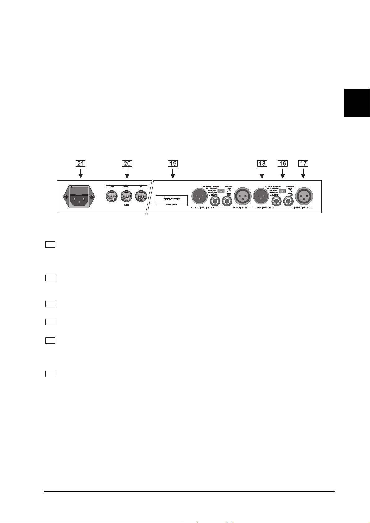
1.3.3 Back panel
E
Fig. 1.4: Back panel connectors and control elements
16
Use the OPERATING LEVEL switch to adapt the MODULIZERPRO to different operating levels. You
can select a -10dBV semi-pro level used for home recording and a +4dBu level used in professional
studios. The level indicators on the front panel are automatically adapted to read the selected nominal
level, i.e. an optimum operating range of the meters is always guaranteed.
17
These are the MODULIZERPROs analog INPUTS. The MODULIZERPRO has both XLR and jack
inputs and outputs. Each XLR and jack set are wired parallel and can be used either balanced and
unbalanced.
18
These are the MODULIZERPROs analog OUTPUTS. Also on balanced or unbalanced XLR or TRS
jacks.
19
These are the MODULIZERPROs MIDI connectors (MIDI OUT / THROUGH / IN). Via these connectors
total remote control is possible.
20
Please take the time to make shure that the SERIAL NUMBER is printed correctly in the space provided
on the enclosed Warranty Registration Card. Put the instruction manual in a safe place and return the
completed Warranty Registration Card to us within 14 days of purchase, making sure that the dealer
stamp has been acquired.
21
This is the MAINS CONNECTOR / FUSE HOLDER / VOLTAGE SELECTOR. Before you connect the
unit, please make sure that the displayed voltage corresponds to your Mains supply. Please note that
the AC voltage selection is defined by the position of the Fuse Holder. If you intend to change the
operating voltage, remove the Fuse Holder and turn it by 180 degrees before you reinsert it. Matching the
two markers monitors the selected voltage. Please note that, depending on the mains voltage supplied
to the unit, the correct fuse type and rate must be installed (see chapter 6.5 SPECIFICATIONS).
Please use the enclosed mains cable to connect the unit to the mains power supply.
+ Please note that not all appliances can be used with different mains voltage ratings. Please
check the description on the back of the unit and the box.
1. INTRODUCTION
11
Page 12

1.4 The effect algorithms
In a digital effects device all effect programs are based on algorithms computed by a Digital Signal Processor
(DSP). How does this work? A DSP can perform an enormous number of binary computations in a minimum
amount of time. The binary computations that are used to generate an effect as part of a program are determined by a so-called algorithm which represents a rule for computing numerical values that are exactly specified for each effect type. For example, tube distortion algorithms differ from chorus algorithms in their programming. Plainly speaking: each effect is based on a specific algorithm which processes the input signal (previously converted from analog to digital). All of this work is done by the DSP. Once the effect has been generated
and added to the input signal, the digital music signal is converted back to analog by means of a D/A converter.
Ultra Phaser
A phaser is one of the MODULIZERPROs classic modulation effects. It is quite popular for guitar sounds and
keyboard pads, but was also extensively used during the 70s for other instruments, such as electric pianos.
From a technical point of view, a phaser is a modulation effect producing a multi-stage phase shift between the
direct and effect signals, which results in a modulated comb filter effect. Depending on how they are set up,
phasers can be used to slightly modulate or heavily distort the signal spectrum. Consequently, the sound they
produce is a bit like that of a regularly modulated filter. Although most often used as a single-instrument effect,
there are well-known examples when phasers are used on mix signals, so do not hesitate to experiment with
it.
The parameters of the phaser:
VARIATION: Speed: determines the LFO speed between 0 (see following Note) and 9.9 Hz.
EDITA: Intensity: adjusts the number of all-pass filters.
EDITB: Depth: is used to set the modulation depth.
EDITC: Feedback: determines how much of the output signal is fed back to the input.
+ When the LFO is set to zero, the modulation stops and can be set manually or via MIDI. To
adjust it manually press EDIT A and EDITB simultaneously. To control it via MIDI you can use
controller # 56. If control send is activated, the MODULIZERPRO sends the actual LFO state,
again using controller # 56. When the LFO is started again it begins on that same value. This
applies to all effect algorithms in which a LFO is used, except the Ultra Chorus.
12
Page 13

+ We recommend that you make frequent A/B comparisons (IN/OUT) between the original and
the processed signals. Rule of thumb: sound-enhancing effects should be missed when absent instead of directly audible. Remember, less is more.
E
13
Page 14

EDITD: Bandlimit: this parameter enables you to filter the feedback path, which is useful for feedback settings of up to 100%.
+ Tip: there is no limitation as to the range of instruments that can be processed with a flanging
effect. Check out vocal sounds too, but remember that less is often more!
Spatial Flanger
Includes an additional stereo effect giving the audio material more room acoustics information. The parameters
are the same as the jetstream flanger.
Ultra Chorus
Think of a string quartet with each musician playing the same notes. As a matter of fact, however, musicians
can never play exactly the same, which results in a sequence of slightly detuned and delayed signals. In a
chorus, copies of the original signal are delayed by 20-40 ms, slightly detuned and modulated by an LFO. The
MODULIZERPRO features no less than 8 voices, which corresponds to a group of 8 musicians playing simultaneously.
The parameters:
VARIATION: Speed: controls the LFO speed between 0.1 and 5 Hz.
EDITA: Delay: this parameter adjusts the delay time (1-80 ms).
EDITB: Depth: sets the modulation depth.
EDITC: Stereo Width: positions the individual voices on the stereo basis.
EDITD: Wideness: controls the effect width by detuning the individual voices against each other.
+ Tip: The Ultra Chorus widens the audio material, for example to enhance thin-texture key-
board pads, give vocals more room acoustics information and guitar sounds a dreamy character.
Stereo Imager
This effect is used to process stereo mix signals, by splitting up the signal in middle and side information (MS
matrix). Both components can be raised separately in level and positioned on the stereo basis. Additionally,
the side signal can be shifted in phase to enhance the stereo effect even further.
The parameters:
VARIATION: Crossover Frequency: adjusts the phase shift onset.
EDITA: Gain: allows for adjusting level corrections (-6 ... +6dB).
EDITB: Spread: sets the intensity of phase shift and thus the stereo width.
EDITC: Mono Pan: positions the mono components on the stereo basis.
EDITD: Stereo Center: positions the stereo components on the stereo basis.
+ With the MIX function the ratio of center vs. side information is controlled
+ When applying increasing stereo width to heavily reverberated audio material, the reverb can
sound unnatural and too intense.
3D Spacemaker
Similar to the Stereo Imager, this algorithm processes the stereo components. Through the use of several
psycho-acoustic phenomena, it also generates a kind of envelope around the room acoustics information and
thus allows for 3D sound with only 2 speakers.
The parameters:
VARIATION: In-Out: selects the type of 3D function (with/without emphasis on middle signals).
EDITA: Gain: allows for adjusting level corrections (-6 ... +6dB).
14
1. INTRODUCTION
Page 15

EDITB: Spread: controls the depth of the sound image.
EDITC: Crossover Frequency: adjusts the 3D effect onset.
In this algorithm the MIX function controls the ratio of middle vs. side signals.
+ When you increase stereo width on heavily reverberated audio material, the reverb can sound
unnatural and too intense.
E
15
Page 16

The parameters:
VARIATION: Bass Frequency: this parameter controls the maximum frequency of bass components to be
retained in the mix signal.
EDITA: Gain: adjusts the level of the output signal by +/-6dB.
EDITB: Bass Pan: adjusts the panorama of the low-frequency range.
EDITC: Treble Pan: controls the stereo balance of the mix signal.
Compressor / Limiter
In broadcasting and recording studios signal levels often exceed the headroom of signal-processing devices
and must therefore be reduced in their dynamics to avoid distortion. This is done with compressors or limiters.
Although these devices perform similar functions they differ in one essential aspect:
Limiters limit signals abruptly above a certain threshold, while compressors provide a smooth control process
over a wider range. The limiter monitors the signal continuously and reduces its dynamics as soon as it
surpasses the threshold. Any signal level exceeding the threshold is immediately cut back to a safe value.
Compressors, too, monitor the program material and work with a threshold. However, they dont control the
signal abruptly as limiters do, but continuously. Once the signal has exceeded the threshold it is smoothly
reduced in level, independently of the amount of excess level. The compressor side-chain implemented in the
DSP1200P has a soft-knee characteristic.
The parameters:
VARIATION: Ratio: controls the ratio of input vs. output level for all signals surpassing the threshold. If set to
maximum, the DSP1200P works as a limiter.
EDITA: Threshold: adjusts the compressor threshold from -60dB to 0dB.
EDITB: Output gain: this parameter allows you to raise or lower the output signal in level by max. 24dB.
EDITC: Attack: the attack control determines the time the compressor needs to respond to signals that are
surpassing the threshold (5-200 ms).
EDITD: Release: controls the time the compressor needs to restore the original level, once the signal has
dropped below threshold (50-500 ms).
+ In all dynamics algorithms the Mix function is disabled: because a compressor processes the
entire signal, any other operating mode would make no sense!
Expander
Many audio signals are limited in their dynamics by nature. For example, recordings made outdoors usually
suffer from a high level of background noise (traffic noise, wind, etc.). Guitar pick-ups, amplifiers, etc. can
produce high noise levels or other sounds that inevitably limit the dynamic range of the wanted signal. Background noise of this kind is inaudible as long as the level of the processed signal is considerably higher than
the noise floor and hence masks the interference noise.
Expanders are used to effectively enlarge the dynamic range of signals by attenuating signals with small
amplitudes, which also reduces the background noise level.
The parameters:
VARIATION: Ratio: this parameter determines the ratio of input vs. output levels for all signals below
threshold.
EDITA: Threshold: adjusts the expander threshold within a range from -60dB to 0dB.
EDITB: Output Gain: allows for raising/lowering the output signal by max. 24dB.
EDITC: Attack: controls the time the expander needs to respond to signals that are below threshold
(5-200ms).
EDITD: Release: sets the time the expander needs to restore the original signal level (1:1) (50-500 ms).
16
1. INTRODUCTION
Page 17

+ Similar to the compressor, there is no need for a Mix function here.
Gate
Noise-gates can be used in a variety of applications, both on stage and for miking instruments in the studio.
For example, they can be used to suppress feedback (e.g. from vocal mics) or to fade out vocal signals (plus
background noise) during pauses. In this case, the gate must reopen very quickly, so that subdued syllables
can be heard. Noise-gates are often used to record or mix drum sets, so as to avoid possible crosstalk-induced
phase problems.
The parameters:
VARIATION: Threshold: determines the threshold below which the gate cuts off the signal.
EDITA: Hold: sets how long signals below threshold can still pass the gate, to allow for a smooth control
process (1-1,000 ms).
EDITB: Range: determines the degree of attenuation when the gate is closed. If set to maximum, the signal
is faded out completely.
EDITC: Attack: sets how fast the gate opens when the signal has surpassed the threshold (1-100 ms).
EDITD: Release: determines how fast the gate closes after the hold time has expired (1-800 ms). The
release time depends on the signal envelope, percussive sounds (short decay) need much quicker release
times than, for instance, sustained keyboard pads.
+ No Mix function.
RingModulator
This effect enables you to distort audio signals in their character. Similar to ultra-short-wave radio, the signal is
multiplied with a carrier frequency, so that a frequency modulation (FM) is produced.
This effect is excellently suited for vocals (robot voice). If set to S0...7 the DSP1200 acts like a sound generator
because now it uses a 1k sine generator (instead of the input signal) as its modulation source.
E
You can adjust the basic carrier frequency, LFO speed and modulation depth. The bandlimit parameter limits
the frequency range of the effect signal, while random and sine generator use an additional 8-step slewing
rate. Additionally, you can edit the basic carrier frequency, modulation depth and LFO speed.
The parameters:
VARIATION: FM Modulation Mode:
L: carrier frequency is modulated by LFO.
E: carrier frequency is modulated by the signal.
R0...7: carrier frequency is modulated by a random generator.
S0...7: 1k sine generator / carrier frequency is modulated by random generator.
EDITA: Frequency: adjusts the carrier frequency.
EDITB: Speed: controls the LFO speed (L), the envelope follower speed (A) or the slew rate of the random
generator (R and S)*).
EDITC: Modulation depth: adjusts...yes, the modulation depth.
EDITD: Bandlimit: this is a subsequent low-pass filter that is used to cut off harsh high-frequency portions. If
set to 0 the filter is bypassed, and as you are increasing the value, the amount of high-frequency portions in the
output signal is being reduced.
+ Caution! If used improperly, the RingModulator effect can damage your hearing or speakers,
as it produces very high-frequency signal portions (particularly if the sine generator is used
which works independently of the input signal)!
1. INTRODUCTION
17
Page 18

Vintager
Digital technology has been trying for years to produce ever more high-quality, low-noise and brilliant sounds,
but most recently more and more people have been going back to the roots looking for the warmth of old
analog sounds. The techno/dance community swears by vinyl anyway, and many a music lover misses the
flair of good old vinyl records and tape machines. The latest trend is called lo-fi.
We have taken this trends into account by creating the Vintager effect. Your recordings will sound like 8-bit
material and produce all those clicks and noises you know from old records!
A TR-808/TR-909-like drum loop sounds really hot only when its fat and dirty!
The parameters:
VARIATION: Clicks Level: adjusts the level of clicks found on old vinyl records.
EDITA: Noise Level: controls the noise intensity.
EDITB: Noise BP: adjusts the sound color of the noise.
EDITC: Crack Level: simulates cracks in the record and adjusts their volume.
EDITD: Hi Cut: turn up this parameter to cut the brilliance of the audio material.
Tube Distortion
®
This effect simulates the sound of three different types of tubes. When you raise the input signal level (e.g.
guitar) to overdrive an analog tube, as found in valve guitar amplifiers, harmonics are added to the original
signal. As distortion increases (also called saturation), the original signal starts to distort and the guitar sound
gets this typical rock music volume and freshness.
The parameters:
VARIATION: Tube Type: use this parameter to select the tube type.
EDITA: In Gain: raises the input signal to reach the sound-modifying areas of the tubes
characteristic curve.
EDITB: Lo Cut: controls a high-pass filter preceding the tube (high frequencies pass).
EDITC: Hi Cut: controls a low-pass filter preceding the tube (low frequencies pass).
EDITD: Bandlimit: controls a band-pass filter after the tube.
+ Try using the tube distortion effect with a kick drum. From dance to R&B anything goes!
Guitar Combo
This effect simulates the audio properties of a complete guitar amp. So, you can connect your bass/guitar to
a preamp and then to the MODULIZERPRO, from where the signal is sent to a mixing console or recording
machine. This algorithm simulates not only two tube stages but also the amps cabinet plus speaker.
The parameters:
VARIATION Type: controls the basic characteristics.
EDITA: In Gain: raises the input signal to reach the sound-modifying areas of the tubes
characteristic curve.
EDITB: Drive: controls the amount of distortion.
EDITC: Presence: adjusts the sounds presence by raising high-frequency components.
EDITD: Speaker: this parameter simulates two types of speakers (incl. cabinet). If set to 0, the speaker
is bypassed.
18
1. INTRODUCTION
Page 19

Guitar Speaker
This effect simulates three different speaker types. Types 1 and 2 are typical guitar amp speakers, while type
3 represents a multimedia speaker. Additionally, you can use a parametric EQ to fine-tune the sound image.
The parameters:
VARIATION: Speaker Type: selects one of three speaker types.
EDITA: Peak Frequency: controls the center frequency of the parametric equalizer.
EDITB: Peak Q: adjusts the bandwidth of the parametric equalizer.
EDITC: Peak Gain: sets the amount of boost or cut of the parametric equalizer.
EDITD: Hi Cut: turn up this parameter to cut the brilliance of the audio material.
+ The multimedia speaker enables you to check your recordings for compatibility. Mix-downs
should sound as transparent and pleasant with small speakers as they do with pro-level studio
monitors. If you use high-grade studio speakers to mix your recordings, it may happen that, for
example, the bass range loses the power it had in the studio when you play back the material
on your ghetto blaster at home: often the smaller speakers simply cannot produce the same
sound as the huge hi-end monitors in the studio.
Super Bass
This is a completely new type of bass exciter effect. In contrast to usual bass exciters that add subharmonics,
this exciter adds specific harmonics to the original signal to generate a psycho-acoustic effect of deep bass
signals. The audience has the impression of hearing an additional subbass.
The algorithm of this effect takes advantage of the fact that the human sense of hearing is used to a natural
succession of harmonics (i.e. fundamental frequency, octave, fifth, etc.) and even reconstructs fundamental
tones that are not part of the original signal. The Super Bass effect creates bass harmonics on the low-end
signals. The listener hears the original bass and these natural harmonics and perceives a fundamental frequency one octave lower than the original frequency. This effect is obtained without increasing the actual power
output of the system significantly. Especially small loudspeaker systems benefit from this effect and can
sound a lot bigger than they actually are.
A kick drum processed with the Super Bass effect gets the right punch to make itself heard in the mix-down.
Bass processors are quite popular in dance/techno music, for example, you can give synthesizer bass lines
much more power.
E
The parameters:
VARIATION: Frequency: adjusts the cutoff frequency of the crossover network.
EDITA: Density: this parameter controls the density of the processed bass signal.
EDITB: Ratio: determines how much the processed bass signal gets compressed.
EDITC: Bass Level: controls the low-frequency response of the original signal (which can even be faded out
completely).
Resonator
A resonator simulates a system that oscillates at one frequency only and hence amplifies this frequency.
The resonator implemented in the DSP1200P can be modulated in its resonance frequency, with positive and
negative feedback of up to 100%. This effect is available in three different modes which can be adjusted with the
VARIATION parameter:
VARIATION: Resonator frequency mode:
L: resonator frequency is modulated by the LFO.
E: resonator frequency is modulated by the signal amplitude.
R0...7: resonator frequency is modulated by the random generator (additional 8-step slew rate is
available in random generator mode).
EDITA: Frequency: controls the basic resonator frequency.
1. INTRODUCTION
19
Page 20

EDITB: Speed: controls LFO speed*) in mode L, envelope follower speed in mode A and random oscillator
speed in modes R0-R7.
EDITC: Depth: determines the modulation depth.
EDITD: Feedback: controls the resonance intensity.
2. OPERATION
2.1 Effects structure
20
Page 21

2.2 Selecting presets
The MODULIZERPRO stores 100 user-definable presets. After power-up, the unit automatically recalls the
preset last used. To select another preset, use the jog wheel to enter the preset number of your choice. Turn
the wheel clockwise to increment the preset number, or counterclockwise to decrement it.
+ Please note that the MODULIZERPRO generally activates the newly selected presets only
after about one second, which is indicated by a dot in the lower right corner of the display.
After loading the data, the MODULIZERPRO enables the preset and the dot disappears. This
brief interruption avoids the direct activation of every preset, as you scroll through the preset
list with the jog wheel. Thus, the MODULIZERPRO makes sure that no "unwanted" programs
are loaded unintentionally. Additionally, you can rotate the jog wheel at high speed and still
have the time to specifically select the preset of your choice, instead of any of its "neighbors".
2.3 Editing programs
Editing programs is easy on the MODULIZERPRO. Basically, all essential parameters can be selected directly via the keypad and edited with the jog wheel. The list to the left of the display summarizes the effect
algorithms that the MODULIZERPRO can generate. Just press the EFFECT key to recall these basic algorithms and directly select them with the jog wheel. With the VARIATION key you can modify the selected
effect in full detail, because each variation not only comprises one parameter but a set of several parameters.
Thus, you can use the various variations to tailor the sound of an effects program to suit your specific needs.
The EDITA and B keys enable you to edit essential single parameters of the selected effects program, while
the EQLO and EQHI keys allow for adapting your own presets to match specific room acoustics or sound
preferences. Finally, you can also save the edits made to the preset.
E
2.4 Saving programs
Use the STORE key to save an edited preset. Basically, all parameter changes can be saved. Whenever
youre editing a preset, the display starts flashing to indicate that the edits will be saved only when you confirm
them by pressing the STORE key twice. Example:
s
You recall a program for editing. Then you edit the preset as desired using the function keys and the jog
wheel. During this process, the flashing STORE key reminds you that the preset settings have been
changed but not saved yet. Press the STORE key once. The display reads the current preset number and
starts flashing. To keep the original preset, use the jog wheel to select another preset that can be overwritten. Press the STORE key again to save the edits to the selected preset. If you wish to overwrite the original
preset, simply press the STORE key twice (after editing) to save all changes you have made.
+ Whenever you have edited a preset and pressed the STORE key twice, all previous settings in
this preset are erased and overwritten with the new parameter values. However, if you wish to
keep the original preset, use the jog wheel to select another preset before you press the
STORE key a second time.
2.5 MIDI control
Use the MIDI key combination to select the MIDI parameters you wish to adjust. For this purpose press and
keep the IN/OUT and the STORE keys for about two seconds. All parameters can be edited with the jog wheel
and the IN/OUT key. The MIDI menu includes five pages which you can select by pressing the IN/OUT key
several times.
On the first page you can select the MIDI channel. The display reads a small c (= channel). The jog wheel
adjusts a channel from 1 through 16. To switch off the MIDI function simply select the 0 value
(displayed as -).
On the second page you can select MIDI Omni mode, i.e. the unit transmits/receives on all 16 MIDI channels.
The display reads O (=Omni). Use the jog wheel to activate (1) or deactivate (0) Omni mode.
The third page allows for configuring controller commands. On its right-hand side, the display reads a capital
C (=Controller). The jog wheel selects one of the following four controller modes:
2. OPERATION
21
Page 22

Display Mode
0 No cont rol ler data is t rans m i tt ed
1 Controll er dat a i s rec eived but not t ransm itt ed
2 Controll er dat a i s t rans m i tt ed but not rec ei ved
3 Controll er dat a i s t rans m i tt ed and rec ei ved
Tab. 2.1: Controller settings
The fourth page gives you access to the program change setup. The display reads a capital P (=Program).
Here, too, four modes can be selected with the jog wheel, as follows:
Display Mode
0 Program c hanges are not trans m i t ted
1 Program c hanges are rec ei ved but not t rans m i tt ed
2 Program c hanges are transm i tt ed but not rec eived
3 Program c hanges are transm i tt ed and rec ei ved
Tab. 2.2: Program change settings
The fifth page of the MIDI menu shows the store enable flag represented by a capital S in the display. The
value 0 disables the reception of controller #60, and therefore protects the user presets from being modified
via MIDI. Accordingly, the value 1 enables MIDI controller #60 so that you can modify or replace presets with
a remote MIDI device or a sequencer. In this case the actual settings will be stored directly to the location that
corresponds to the controller value.
+ Attention! Since the store enable mode allows you to access memory locations directly via
MIDI, it is possible that stored presets will be replaced or altered if controller #60 messages are
sent on the same MIDI channel. The purpose of this mode is to facilitate MIDI backup and
restore operations without express confirmation at the MODULIZERPRO. It is therefore recommended to disable (flag=0) this mode as soon as the intended data transfer has ended. This is
done automatically when you switch off the MODULIZERPRO.
On the sixth, and presently the last, page you can access the System Exclusive functions. This is indicated
by a d (for dump) in the display. To the left of this d a number is displayed:
- 0 means that no SYSEX data will be sent or accepted.
- 1 will enable the MODULIZER PRO to receive data. When STORE is pressed the unit will wait for data, this
is shown by flashing dots (LEDs) in the display. The MIDI button LED flashes signaling that SYSEX data is
being received.
- 2 will enable the MODULIZER PRO to send a bulk dump. Start your sequencer and press STORE on the
DSP1200 to start the transmission.
To load these settings again, select 1, press STORE and start your sequencer. If you press IN/OUT again, you
will leave the MIDI setup. You can at all times press any other key to leave the MIDI setup directly.
If you press the IN/OUT key again on the sixth page, the MODULIZERPRO quits MIDI setup mode.
+ During a bulk dump all audio functions of the MODULIZERPRO will be deactivated.
The full-featured MIDI implementation of the MODULIZERPRO allows for easily integrating the MODULIZERPRO
into any MIDI system.
s MIDI IN
Any MIDI data sent to the MODULIZERPRO (sequencer, MIDI footswitch, etc.) is received via the MIDI IN jack.
For example, when you wish to use the MODULIZERPRO as an effects devices for your guitar rack, you can
connect the MIDI IN jack to a MIDI footswitch that allows for selecting program presets. If your rack includes
another MIDI effects devices (e.g. a multi-effects processor), the data sent from the MIDI footswitch can be
routed via the MODULIZERPRO's MIDI THRU jack to your multi-effects processor.
22
2. OPERATION
Page 23

s MIDI THRU
The MIDI THRU jack is used to loop through incoming MIDI data, i.e. any control data received at the MIDI IN
of the MODULIZERPRO can be transmitted via the MIDI THRU jack to other MIDI devices/instruments.
s MIDI OUT
The MIDI OUT jack allows for transmitting MIDI data that originate from the MODULIZERPRO. We are cur-
rently developing a software editor which will allow for storing single items of the MODULIZERPRO's internal
data on an external medium, by using controller commands. Thus, it will be possible to archive MODULIZERPRO
settings and presets on a computer, sequencer or MIDI data recorder. Both MIDI Control Change and MIDI
Program Change commands will be transmitted when you edit or recall filter settings. Detailed information on
this future control are available from our BEHRINGER hotline (+49(0)2154-920666), our international distributors and/or our Internet homepage http://www.behringer.de.
2.5.1 Modulation-controller
It is even possible to modulate some of the LFO effects manually or via MIDI. You can access the modulation
value pressing EDIT A and EDITC at the same time while LFO speed is set to zero. The modulation status can
now be controlled with the jog wheel; i.e. you can set and change the delay used by the MODULIZER PRO
manually to create a Doppler effect. If you try to change the modulation parameter while the LFO speed is not
zero the display will show a dot in the lower right corner signaling that no changes can be made.
+ With this function you can also determine the starting point for a modulation effect. When the
LFO is started again it begins on the value set by the jog wheel.
You can also control the modulation via MIDI by a sequencer for instance. To control it via MIDI you can use
controller # 56. If control send is activated, the MODULIZERPRO sends the actual LFO state, again using
controller # 56. As with manual control, the MODULIZERPRO will only accept controller values if the LFO
speed is set to zero. This applies to all effect algorithms in which a LFO is used, except the Ultra Chorus.
E
3. APPLICATIONS
The BEHRINGER MODULIZERPRO is a highly flexible device that can be used for a wide variety of applications. Prior to a presentation of the MODULIZERPROs many uses, please note the following remarks on how
to set signal levels correctly.
3.1 Level setting
Take care to set levels properly on the MODULIZERPRO! Low levels deteriorate the dynamics of the music
signal, which results in a poor, weak and noisy sound. On the other hand, excess levels overdriving the
converters in the MODULIZERPRO should also be avoided. Digital distortion is (unlike its analog counterpart)
very unpleasant to hear as it does not occur gradually but abruptly.
Use the input level meter of the MODULIZERPRO to adjust the input signal to about -10dB. Make sure that
the CLIP LEDs never light up!
3.2 Using the MODULIZERPRO in the aux bus
By using the MODULIZERPRO in an aux bus of your mixing console you can feed the channel signals of one,
several or even all console channels into the MODULIZERPRO, i.e. for each channel you can use the aux
busses to separately determine the reverb levels of, for instance, various drum sounds: while lots of reverb is
applied to the snare drum, the effect intensity could be reduced in the channels assigned to the tom-toms. To
use the MODULIZERPRO in the aux bus, the unit must be wired as follows:
3. APPLICATIONS
23
Page 24

24
Page 25

E
25
Page 26

can wire the MODULIZERPRO in stereo. Connect the preamp to the audio inputs of the MODULIZERPRO,
and the audio outputs (left/right) to one channel each of the power amp (left/right).
+ Since most guitar amps only have a serial insert loop, you should make sure that the
MODULIZERPRO is set to Mix-Intern mode. In this mode you can control the effect intensity
applied to the guitar signal. However, if your amp features a parallel effect loop which allows
for adding the effect-signal portion (similar to an aux path in a mixing console), we recommend that you use the MODULIZERPROs Mix-Extern mode. In this case, the effect intensity
present at the output of the MODULIZERPRO is 100%, and you can use the effect loop to
determine the amount of effect added to the guitar signal.
Instrumentalists can benefit from a variety of advantages offered by the MODULIZERPRO's MIDI implementation. For example, you can use a MIDI footswitch board to send program change commands via MIDI. Connect
the MIDI OUT jack of your MIDI board to the MIDI IN jack on the MODULIZERPRO. If the MODULIZERPRO
fails to respond to the program change commands sent from the MIDI board, check the MIDI channel settings.
Consult the users manual of your MIDI board to find out on which channels program change commands are
transmitted (usually in Omni mode). Set the MIDI channels appropriately in MIDI mode (see 6.3) and enable
the MODULIZERPRO to receive program change commands.
If your MIDI board features a controller or allows you to connect controller pedals, you can even change
parameter settings via MIDI while playing. For instance, you can freely change the effect intensity from
0-100% while playing (Contr. 27, Value 0-100). Set the controller for Mix-Intern mode (Contr. 30, Value 0) so
that it can be used to increase the effect intensity. In this way, guitar solos can be enhanced with chorus and
delay effects, while the effect intensity is gradually reduced when playing rhythm. You can even control the
function of the IN/OUT switch to bypass the MODULIZERPRO when an unprocessed signal is needed. Basically, all MIDI devices that are capable of transmitting MIDI controller commands, e.g. keyboards/sequencers,
will allow for using these features.
The MODULIZERPRO may also be inserted between the outputs of a keyboard and the inputs of a mixing
console. If required, adapt the levels with the Operating Level switch.
3.5 Using the MODULIZERPRO in a MIDI system
With its built-in MIDI interface the MODULIZERPRO can be integrated into any MIDI system, where it transmits and receives both program change and controller change information to perform program changes via MIDI
from a sequencer or any other MIDI device. Wire and set up the MODULIZERPRO as shown below:
Fig. 3.4: Connecting the MODULIZERPRO via MIDI to a sequencer/computer and a keyboard (option)
26
3. APPLICATIONS
Page 27

3.6 Saving data via MIDI
The MODULIZERPROs MIDI implementation also allows for archiving one or several presets on an external
storage medium. Proceed as follows:
Connect the MIDI OUT jack of the MODULIZERPRO to the MIDI IN jack of a MIDI data recorder (e.g. sequencer). Press the STORE and IN/OUT keys simultaneously to enter MIDI mode. Set program change mode
to 0 and controller change mode to 3. Now quit MIDI mode by pressing the STORE key. Use the jog wheel to
select the preset whose data you wish to save. When the preset is activated its parameters are transmitted as
controller data and can be recorded on a sequencer or similar device. Repeat this routine until all presets of
your choice have been sent to the external data recorder.
To load archived data back into the MODULIZERPRO, you must enable controller reception in MIDI mode (see
2.5). Then, start the sequencer to automatically transmit each preset data set back to the MODULIZERPRO.
Press the STORE key, select a program location to store the data and then again press the STORE key. If you
want to automate MIDI store functions you must enable the store mode, to switch on the reception of controller
#28. This allows you to directly store any modification of the actual preset on the preset number that is
transmitted with the controller. You can also restore a complete preset that has previously been recorded with
a MIDI sequencer on the same location it had before.
4. TECHNICAL BACKGROUND
4.1 Digital audio processing
E
In order to convert an analog signal - e.g. music - into a series of digital words, a so-called Analogue to Digital
Converter or ADC is used. The converter functions by viewing the signal entering it a given number of times
over a period of time, e.g. 44,100 times per second, giving a rate of 44.1 kHz, and in each case measuring the
signal amplitude, and giving it a numerical value. This form of measuring the signal regularly over a period of
time is known as sampling, the conversion of the amplitude into a numerical value, quantizing. The two
actions together are referred to as digitizing.
In order to carry out the opposite - the conversion of a digitized signal into its original analogue form - a Digital
to Analogue Converter or DAC is used. In both cases the frequency at which the device operates is called the
sampling rate. The sampling rate determines the effective audio frequency range. The sampling rate must
always be more than twice the value of the highest frequency to be reproduced. Therefore, the well known CD
sampling rate of 44.1 kHz is slightly higher than twice the highest audible frequency of 20 kHz. The accuracy
at which quantization takes place is primarily dependent on the quality of the ADCs and DACs being used.
The resolution, or size of digital word used (expressed in bits), determines the theoretical Signal/Noise ratio (S/
N ratio) the audio system is capable of providing. The number of bits may be compared to the number of
decimal places used in a calculation - the greater the number of places, the more accurate the end result.
Theoretically, each extra bit of resolution should result in the S/N ratio increasing by 6dB. Unfortunately, there
are a considerable number of other factors to be taken into account, which hinder the achievement of these
theoretical values.
If you picture an analog signal as a sinusoidal curve, then the sampling procedure may be thought of as a grid
superimposed on the curve. The higher the sampling rate (and the higher the number of bits), the finer the grid.
The analog signal traces a continuous curve, which very seldom coincides with the cross points of the grid. A
signal level at the sampling points will still be assigned a digital value, usually the one closest to the exact
representation. This limit to the resolution of the grid gives rise to errors, and these errors are the cause of
quantizing noise. Unfortunately, quantizing noise has the characteristic of being much more noticeable and
unpleasant to the ear than natural analog noise.
4. TECHNICAL BACKGROUND
27
Page 28

1101
1011
U (Voltage)
0000
1111
1110
1100
8
7
6
5
4
0011
3
0010
0001
1 2 3 4 5 6 7 8
-1
-2
-3
-4
-5
-6
-7
-8
0110
0101
0100
0111
Conversation Rate
Continuous
Analog Signal
t (Time)
Quantization Steps
-8 -7 -6 -5 -4 -3 -2
Quantization Errors
(Noise)
1010
1001
1000
Digital Words
Fig. 4.1: Transfer diagram for an ideal linear ADC (2s complement representation)
In a digital signal processor, such as the DSPs in the MODULIZERPRO, the data will be modified in a number
of ways, in other words, various calculations, or processes, will be done in order to achieve the desired effect
on the signal. This gives rise to further errors, as these calculations are approximations, due to their being
rounded off to a defined number of decimal places. This causes further noise. To minimize these rounding off
errors, the calculations must be carried out with a higher resolution than that of the digital audio data being
processed (as a comparison, an electronic calculator may operate internally with a greater number of decimal
places than can be shown on its display). The DSPs in the MODULIZERPRO operate with a 24 bit resolution.
This is accurate enough to reduce quantizing noise to levels which are usually below the audible threshold.
However, when using extreme equalizer settings, some quantizing side effects may be detected.
Digital sampling has one further, very disturbing effect: it is very sensitive to signal overload. Take the following
simple example using a sine wave. If an analog signal starts to overload, it results in the amplitude of the signal
reaching a maximum level, and the peaks of the wave starting to get compressed, or flattened. The greater the
proportion of the wave being flattened, the more harmonics, audible as distortion, will be heard. This is a
gradual process, the level of distortion as a percentage of the total signal rising with the increase of the input
signal level.
Digital distortion is quite different, as illustrated by this simplified example. If we take the situation where a 4 bit
word has the positive maximum value of 0111, and add to it the smallest possible value of 0001 (in other words,
the smallest increase in amplitude possible), the addition of the two results in 1000 - the value of the negative
maximum. The value is turned on its head, going instantly from positive max to negative max, resulting in the
very noticeable onset of extreme signal distortion.
4.2 Reverberation and reflection
In a concert hall the sound the listener hears comprises both the source signals (e.g. acoustical instruments,
P.A. system) and thousands of reflections of these "primary signals", which bounce off floor, ceiling and walls
to reach the ear after a short delay. These reflections represent thousands of echoes of the direct signal, which
are not perceived any longer as single echoes but - due to their sheer number - as reverberation. Basically, the
reflected signal portions reach the ear later than the source signal, and the very fact that they do not arrive from
the same direction as the direct signal (see fig. 4.2), makes it possible to hear spatial information, i.e. to
perceive the direct signal as it is embedded in the room acoustics.
28
4. TECHNICAL BACKGROUND
Page 29

Stage
E
Early Reflections
Fig. 4.2: Direct and reflected sounds reaching the listeners ear.
Spatial information is an important means of orientation, because human hearing is also used to determine the
position of a sound source. In certain situations, this capability can be very useful or even of vital importance.
The fact that we can actually hear the size of a room shows how strongly developed the human sense of
hearing actually is. Based on the reflectivity of a room, we can also distinguish (though we often dont know
how) the materials it consists of. In large rooms with high tiled walls reverberation is generally very dense and
needs some time to decay, while a small room with many objects in it (furniture, carpets, etc.) features very
short reverberation often not even perceived as such. Nevertheless, this extremely short reverb does exist,
which is the reason why many designers of reverb devices (such as our VIRTUALIZERPRO ) implement
several basic reverb types and give them specific room names. It is quite natural, for example, that a reverb
preset called "Cathedral" produces a long and highly dense reverb, while a "Room" program usually represents
the acoustics of a room that is much smaller in size.
Direct Sound
Early Reflections
Listening Position
Diffuse Reflections
In addition to the capability of human hearing to determine the direction from where a sound phenomenon
arrives, we can also hear modulations of acoustic events. Of importance in this context is the frequency of the
modulated signals. Frequency modulations below 100 Hz are virtually inaudible. However frequency modulations can clearly be heard when occurring in the midrange frequency band, due to the "sensitivity" of human
hearing. The ear immediately detects changes in midrange frequencies, while its sensitivity to frequency
modulation in the extreme low end of the frequency spectrum is reduced.
Frequency modulation can also be used to produce wanted effects. The popular chorus effect, for instance, is
basically the sum of a variety of frequency modulations. The original signal is slightly delayed in the chorus
algorithm, then added again and modulated by means of an oscillator. Subsequently, modulating frequencies
(of different pitch) are applied to the original signal, which produces the well-known floating chorus sound.
Basically, frequency modulation is the starting point for all kinds of chorus-type effects: by simply adding the
delayed signal, without modulating the original, you can produce a delay effect. Since chorus effects use very
short delay times, the resulting delay effect is not perceived as such. However, when you increase the delay
time, there is a clear gap between original and effect signals, and delay becomes audible.
4.3 Audio dynamics
By employing current modern analog technology it is possible to manufacture audio equipment with a dynamic
range of up to 130dB. In contrast to analog techniques, the dynamic range of digital equipment is approximately 25dB less. With conventional record and tape recorder technology, as well as broadcasting, this value
4. TECHNICAL BACKGROUND
29
Page 30

is further reduced. Generally, dynamic restrictions are due to noisy storage in transmission media and also the
maximum headroom of these systems.
4.3.1 Noise as a physical phenomenon
All electrical components produce a certain level of inherent noise. Current flowing through a conductor leads
to uncontrolled random electron movements. For statistical reasons, this produces frequencies within the
whole audio spectrum. If these currents are highly amplified, the result will be perceived as noise. Since all
frequencies are equally affected, we term this white noise. It is fairly obvious that electronics cannot function
without components. Even if special low-noise components are used, a certain degree of basic noise cannot
be avoided.
30
Page 31

aid of a volume fader, which manually levels the material. During low passages the gain is increased, during
loud passages the gain is reduced. Of course it is fairly obvious that this kind of manual control is rather
restrictive; it is difficult to detect signal peaks and it is almost impossible to level them out. Manual control is
simply not fast enough to be satisfactory.
Fig. 4.4: The interactive relationship between the operating level and the headroom
E
The need therefore arises for a fast acting automatic gain control system which will constantly monitor the
signals and which will always adjust the gain to maximize the signal-to-noise ratio without incurring signal
distortion. This device is called a compressor or limiter. This system is a part of the BEHRINGER
MODULIZERPRO.
4.3.3 Compressors/limiters
With broadcasting and recording, signal peaks can easily lead to distortion due to the high dynamic range of
microphones and other musical equipment. Compressors and limiters reduce the dynamics by means of an
automatic gain control. This reduces the amplitude of loud passages and therefore, restricts the dynamics to
a desired range. This application is particularly useful with microphones, to compensate for level changes.
Although compressors and limiters perform similar tasks, one essential point makes them different: limiters
abruptly limit the signal above a certain level, while compressors control the signal gently over a wider range.
Both continuously monitor the signal and intervene as soon as the level exceeds a user-adjustable threshold.
Any signal exceeding this threshold will be immediately reduced in level.
Limiters reduce the output level to the adjusted threshold whenever the input signal exceeds this point. With
compression, in contrast to the action of a limiter, the signal is reduced in gain relative to the amount the signal
exceeds the threshold. The output of a compressor will still rise if the input level is increased, while the
maximum output of a limiter will always be equal to the threshold level.
Generally, threshold levels for compressors are set below the normal operating level to allow for the upper
dynamics to be musically compressed. For limiters, the threshold point is set above the normal operating level
so that it only intervenes to protect subsequent equipment from signal overload.
The speed, or rather time settings used can differ greatly depending on use. Although both limiter and compressor use very short attack times, the release time of a compressor are in the 100 ms region whereas a
limiter uses release times of seconds. To be exact: The release time is a time constant of an exponential
function. It is the time it takes the gain reduction to decrease by 63.2% (= 8.7dB).
Because fast level changes are more noticeable than slow changes, long release time are used where unobtrusive signal processing is required. In some cases however, the principal goal is to protect devices as loudspeakers and power amplifiers. In those cases a short release time is more appropriate to ensure that the
limiter only intervenes when it is needed and the level returns to normal as soon as possible.
Long release times are better suited when the limiter should remain inaudible for instance with broadcasting
or club applications or when a signal is transferred to (analog) tape. Please note that when using slow release
4. TECHNICAL BACKGROUND
31
Page 32

times you should switch to the level meter menu where the functioning of the limiter can be monitored.
4.3.4 Expanders/noise-gates
Audio, in general, is only as good as the source from which it was derived. The dynamic range of signals will
often be restricted by noise. Synthesizers, effects devices, guitar pickups, amplifiers etc. generally produce a
high level of noise, hum or other ambient background hiss, which can disturb the quality of the program
material.
Normally these noises are inaudible if the level of the desired signal lies significantly above the level of the
noise. This perception by the ear is based on the masking effect: noise will be masked and thus becomes
inaudible as soon as considerably louder sound signals in the same frequency band are added. Nevertheless,
the further the level that the desired signal decreases, the more the noise floor becomes a disturbing factor.
Expanders or noise-gates offer a solution for this problem: these devices attenuate signals when their amplitudes drop, thereby fading out the background noise. Relying on this method, gain controlling amplifiers, like
expanders, can extend the dynamic range of a signal and are therefore the opposite of a compressor.
In practice, it is shown that an expansion over the entire dynamic range is not desired. With an expansion ratio
of 5:1 and a processed dynamic range of 30dB, an output dynamic range of 150dB will be the result, exceeding all subsequent signal processors, as well as human hearing. Therefore, the amplitude control is restricted
to signals whose levels are below a certain threshold. Signals above this threshold pass through the unit
unchanged. Due to the continuous attenuation of the signals below this threshold, this kind of expansion is
termed downward expansion.
The noise-gate is the simplest form of an expander: in contrast to the expander, which continuously attenuates
a signal below the threshold, the noise-gate cuts off the signal abruptly. In most applications this method is not
very useful, since the on/off transition is too drastic. The onset of a simple gate function appears very obvious
and unnatural. To achieve inaudible processing of the program material, it is necessary to be able to control the
signals envelope parameters. This is part of the many features of the MODULIZERPRO.
4.4 Artificial harmonics generation
By 1955 an American, Charles D. Lindridge, had already invented the first EXCITER (a unit that EXCITES
upper harmonics), when he presented a unit for improving the sound of music and speech. He enriched signal
sources with artificially generated upper harmonics and found that both sound quality, transparency and perceived positioning of musical instruments could be considerably improved using this effect. He was granted an
American patent on his circuit design under the number US 2 866 849.
Compared to modern technology, Lindridges circuit was anything but fully developed, however, it featured
many of the aspects found in todays modern circuit designs. Psycho-acoustic discoveries and greater knowledge, gathered over the years, have allowed for new and improved circuit designs, through the use of advanced
technology.
Vacuum tubes also produce harmonics as a result of distortion caused by saturation. In general, the saturation
(overdriving) of transistor and tube-based circuits results in different types of distortion. Distortion caused by
tubes is generally considered to be more pleasant and warm, often enhancing the quality rather than deteriorating it. With the MODULIZERPRO various tube types and their specific sound can be emulated.
4.5 Tube technology
A closer look at developments and trends in audio technology shows that tubes are currently enjoying a
renaissance, in a time when even amateur musicians are free to use digital effects processors and recording
media, and ever more affordable digital mixing consoles are becoming a natural part of the equipment of many
semi-professional studios. The manufacturers try with ever new algorithms to get the most out of DSPs (Digital
Signal Processors), the heart of any digital system.
Still, many audio engineers, particularly old hands often prefer using both old and new tube-equipped devices.
As they want to use their warm sound character for their productions, they are ready to accept that these
goodies produce a higher noise floor than modern, transistor-based devices. As a consequence, you can find
a variety of tube-based microphones, equalizers, preamps and compressors in todays recording and mastering environments. The combination of semiconductor and tube technologies gives you the additional possibility
of using the best of both worlds, while being able to make up for their specific drawbacks
32
4. TECHNICAL BACKGROUND
Page 33

Tubes do not however have the same task in a recording studio as in an overdriven guitar amp, where the
considerably higher saturation of the tube(s) leads to a full and often deliberate modification of the input signal
(in many cases combined with a heavy increase in noise floor levels). In the studio more subtle effects are
needed. Here, tube circuits add life to the signals tonal character and increase its power to make itself heard.
Often, tubes also increase the signals perceived loudness (in relation to the unprocessed signal), i.e. the
perceived loudness goes up although the volume level remains the same. This is because the dynamic range
of the applied audio signal is limited by the tube circuit, while the amplitude of the signal with the lowest
loudness is raised. Thus, increasing tube saturation produces a slight compression effect over the entire
dynamic range.
A similar effect can be perceived when analog tape is saturated. This saturation effect also compresses the
recorded audio material and produces additional harmonics.
The BEHRINGER MODULIZERPRO is equipped with tube emulation algorithms that due to extensive research deliver very subtle and natural sound effects. These newly developed algorithms are capable of delivering both the subtle nuances of a tube as the strong coloration as produced by heavy saturation.
5. INSTALLATION
Your BEHRINGER MODULIZERPRO was carefully packed in the factory and the packaging was designed to
protect the unit from rough handling. Nevertheless, we recommend that you carefully examine the packaging
and its contents for any signs of physical damage, which may have occurred in transit.
+ If the unit is damaged, please do not return it to us, but notify your dealer and the shipping
company immediately, otherwise claims for damage or replacement may not be granted.
Shipping claims must be made by the consignee.
E
5.1 Rack mounting
The BEHRINGER MODULIZERPRO fits into one standard 19" rack unit of space (1 3/4"). Please allow at least
an additional 4" depth for the connectors on the back panel. Be sure that there is enough air space around the
unit for cooling and please do not place the MODULIZERPRO on high temperature devices such as power
amplifiers etc. to avoid overheating.
5.2 Mains connection
The mains connection of the MODULIZERPRO is made by using a mains cable and a standard IEC receptacle. It meets all of the international safety certification requirements.
+ Please make sure that all units have a proper ground connection. For your own safety, do not
remove the ground connection within the units or at the supply, or fail to make this connection
at all.
Before you switch on the unit, check that it is configured to match your AC mains voltage requirements. If it
does not comply, then it is necessary to switch the operating voltage to the correct supply requirements
BEFORE turning on the unit, otherwise the unit could be severely damaged. You will find this combined fuse
holder/voltage selector at the back, adjacent to the IEC receptacle. IMPORTANT: This does not apply for
general export models which are built for one operating voltage only.
The AC voltage selection is defined by the position of the fuse holder. If you intend to change the operating
voltage, remove the fuse holder and twist it by 180 degrees before you reinsert it. Matching the two markers
monitors the selected voltage.
+ If the unit is switched to an other operating voltage, the ruse rating must be changed. See the
technical specifications in the appendix.
A safety fuse protects the unit from serious defects. If the fuse blows, this is a warning sign and always
indicates that the circuit is overloaded. The fault must always be repaired before the fuse is replaced. If the
safety fuse is faulty and needs replacing after the unit is repaired, please make sure that you replace it only
5. INSTALLATION
33
Page 34

with the identical type and rating. NEVER use fuses of different ratings or cover faulty fuses with aluminium foil.
This can cause fire and electric shocks and will endanger your life and the lives of others.
5.3 Audio connections
As standard, the BEHRINGER MODULIZERPRO is installed with electronically servo-balanced inputs and
outputs. The new circuit design features automatic hum and noise reduction for balanced signals and thus
allows for trouble-free operation, even at high operating levels. Externally induced mains hum etc. will be
effectively suppressed. The automatic servo-function recognizes the presence of unbalanced connectors and
adjusts the nominal level internally to avoid level differences between the input and output signals (correction
6dB).
+ Please ensure that only qualified persons install and operate the MODULIZERPRO. During
installation and operation the user must have sufficient electrical contact to earth. Electrostatic charges might affect the operation of the MODULIZERPRO!
Cable InputOutput
Pin 1
2 1
Pin 2 = (+) Signal Positive
Shield
(+) Signal + Hum
(-) Signal + Hum
3
Pin 3 = (-) Signal
RFI and Hum
1 2
3
Ground
Negative
Fig. 5.1: Compensation of interference with balanced connections
(+)Hum + Signal
(-)Hum + Signal
2 x Signal
= Signal + 6 dB
34
5. INSTALLATION
Page 35

Unbalanced use of
mono 1/4" jack plugs
Balanced use of
stereo 1/4" jack plugs
E
Ring
Balanced use with XLR connectors
35
Page 36

5.5 Operating level switch
To adapt the MODULIZER PRO to the used operating level, the unit can be switched between homerecording
level (-10dBV) and professional level (+4dBu). Use the LED bars on the frontpanel to determine the optimal
setting. The Level indicators should read somewhere between -10 and -6dB, while the Clip LED should not
light up at all.
6. APPENDIX
6.1 Parameter overview
No. EFFECT VARIATION Edit A Edit B Edit C Edit D
1 Ultra Phaser LFO Speed * Intensity Depth Feedback
2 Spatial Phaser LFO Speed * Intensity Depth Feedback
3 Harmonic Exciter HP Shape Tune Harmonics
4 Auto Lowpass Mode (LFO, Auto 12/24 dB) Frequency Resonance Mod. Depth Env. / LFO Speed *
5 Auto Highpass Mode (LFO, Auto 12/24 dB) Frequency Resonance Mod. Depth Env. / LFO Speed *
6 Auto Bandpass Mode (LFO, Auto 12/24 dB) Frequency Resonance Mod. Depth Env. / LFO Speed *
7 Jetstream Flanger LFO Speed * Delay Depth Feedback Band Limit
8 Spatial Flanger LFO Speed * Delay Depth Feedback Band Limit
9 Ultra Chorus LFO Speed Delay Depth Stereo Width Wideness
10 Stereo Imager Xover Freq. Gain Spread Mono Pan. St. Center
11 3D Space Maker In / Out Gain Spread Xover Freq.
12 Denoiser Gate Thresh. Gate Hold Gate Rel. LP Freq. LP Depth
13 Ultra Ambience Pre Delay Size Wall Damp Stereo Widt h Reflections
14 Voice Canceler Bass Freq. Gain Bass Pan. Treble Pan.
15 Comp./Limiter Ratio Threshold Out Gain Attack Release
16 Expander Ratio Threshold Out Gain Attack Release
17 Noise Gate Threshold Hold Range Attack Release
18 Ring Modulator Mode (LFO, Auto, RND) Carrier Freq. LFO / Speed * Mod. Depth Band Limit
19 Vintager Clicks Level Noise Level Noise BP. Buzz Level Signal BP.
20 Tube Distortion Tube Type In Gain Low Cut High Cut Band Limit
21 Guitar Combo Type In Gain Drive Presence Speaker
22 Guitar Speaker Speaker Type Peak Freq. Peak Q Peak Gain HF Cut
23 Super Bass Frequency Density Ratio Bass Level
24 Resonator Mode (LFO, Aut o, RND) Frequency LFO / Speed * Mod. Depth Feedback
* User/controller defined fixed/start value when set to 0
36
Tab. 6.1: Parameter overview for the different effect types
6. APPENDIX
Page 37

6.2 Variation table
No. Effect
1 Ultra Phaser 0..127 *) 1..8 0..127 0..127 - 0..100
2 Spatial P haser 0..127 *) 1..8 0..127 0..127 - 0..100
3 Harmonic Exciter 0..127 0..127 0..127 - - 0..25 1.)
4 Auto Lowpass L1, L2, A1, A2 0..127 0..127 0..127 0.. 127 *) 0..100
5 Auto Highpass L1, L2, A1, A 2 0..127 0..127 0..127 0..127 *) 0..10 0
6 Auto Bandpass L1, L2, A1, A 2 0..127 0..127 0..127 0..127 *) 0..10 0
7 Jetstream Flanger 0..127 *) 1..128 0..127 -100..+100 0..127 0.. 1 0 0
8 Spatial Flanger 0..127 *) 1.. 128 0..127 -100..+100 0..127 0..100
9 Ultra Chorus 0..127 1..128 0..127 0..127 0..127 0..100
10 Stereo I mager 0..127 -6.0..+6.0 0. .127 - 100..+100 -100..+100 0..100 2.)
11 3D Spac e M aker 1,2 -6.0..+6.0 0..127 0..127 - 0..100 2.)
12 Denoiser 0..127 0..127 0..127 0..127 0..127 13 Ultra Am bience 0..127 0..127 0..127 0..127 1..15 0..100
14 Voice Canceler 0.. 127 -6.0. .+6.0 -100..+100 -100..+100 - 0.. 100 2.)
15 Comp./Limiter 0..24 -60..+0 -24 ..+24 0..127 0..127 16 Expander 0..24 -60..+0 -24 ..+24 0..127 0..127 17 Noise Gate 0..127 0..127 0..127 0..127 0..127 18 Ring Modulator L,E,R0..7,S0..7 0..127 0..127 *) 0. .127 0..127 0..100
19 Vintager 0..127 0..127 0..127 0..127 0..127 0..100
20 Tube Di stor tion 1,2,3 0..127 0..127 0..127 0..127 0..100
21 Guitar Combo 1. .3 0..127 0..127 0..127 0,1,2 0..1 00
22 Guitar Speaker 1,2,3 0..127 1.0..10.0 -12.0.. +12.0 0..127 0..1 00
23 Super Bass 0..127 0..127 0..6 0..127 - 24 Resonator L, E, R0. .7 0..127 0.. 127*) 0.127 -100..+100 0 . .100
Variation Edit A Edit B Edit C Edi t D Mix
Range Range Range Range Range Range
E
Tab. 6.2: Variation range
1.) Exciter: Insert: Dry = 0% / Wet = 100%
2.) Mix = M-S-Matrix (Dry = Mono / Wet = Stereo) / Insert function is cancelled.
*) Additional Modulation-Controller When LFO SPEED = 0
6. APPENDIX
37
Page 38

6.3 MIDI implementation
Function Transmitted Recognized Rem arks
MIDI Implem entatio n Chart
Basic
Channel
Mode
Not e Nu mbe r
Velocity
After Touch
Default
Changed
Default
Messages
Altered
Tru e Vo ice
Note ON
Note OFF
Key´s
Ch´s
OFF, 1 - 1 6
OFF, 1 - 1 6
1,2, 3,4
X
X
X
X
X
X
X
X
OFF, 1 - 16
OFF, 1 - 16
1,2,3,4
X
X
X
X
X
X
X
X
memorized
Pitc h Bender X X
Control O 50 - 62 O 50 - 62 see add. Table
Progr.
Change
Tru e #
O (0-99)
1-100
O (0-9 9)
1-100
System Exclusive X X
System
Common
System
Real Time
Aux
Messages
Song Pos
Song Sel
Tune
Clock
Comma nd s
Local ON/OFF
All notes OFF
Acti ve Sense
Reset
X
X
X
X
X
X
X
X
X
X
X
X
X
X
X
X
X
X
Notes
O = YES, X = NO
Mode 1: OMNI ON, POLY
Mode 2: OMNI ON, MONO
Mode 3: OMNI OFF, POLY
Mode 4: OMN I OFF , MONO
Tab. 6.3: MIDI implementation chart
Parameter Name D isplay
Range
Effect 1..24 50 0..23
Variation dep. on eff ec t* 51 0..xxx
Edit A " 52 "
Edit B " 53 "
Edit C " 54 "
Edit D " 55 "
Modulati on C ontroller 0. . 127 56 0.. 127
EQ Low -16..16 57 0..32
EQ High -16..16 58 0..32
Mix 0..100 59 0..100
Store 1..100 60 0..99
In/Out 61 0= Out, 1=In 1 0
External/Internal Mix --/(Mix) "-- "= Ext 62 0= Ext, 1= Int
* nF = no func tion
Midi-
Controller
Controller
Range LEDs
Tab. 6.4: Controller functions with MIDI
38
6. APPENDIX
Couple Lef t Right I N on IN off
Page 39

6.4 Default settings
Edit C Edit D MixEffectNo. Variation Edit A E dit B
1 Ultra Phaser 51 6 100 127 - 70
2 Spatial Phaser 60 8 80 90 - 70
3 Harmonic E xcit er 15 90 60 - - 24
4 Aut o Lowpass A2 60 70 127 29 80
5 Auto Highpass L2 20 110 127 40 80
6 Auto Bandpass A2 70 60 127 10 80
7 Jetstream Flanger 40 4 100 +100 50 50
8 Spatial F langer 60 8 127 +100 95 50
9 Ultra Chorus 10 60 100 127 20 50
10 Ster eo Imager 100 -2.0 + 0.0 +0.0 50 60
11 3D Space Maker 1 +3.0 80 20 - 60
12 Denoiser 40 40 10 75 1 27 13 Ul t r a Ambience 30 127 52 127 15 40
14 Voice Canc eler 85 +2.0 +0 +0 - 100
15 Comp./ Limi ter 12 -26 dB + 6 dB 30 70 16 Ex pander 3 -26 dB 0 dB 50 60 17 Noise Gat e 60 40 20 20 30 18 Ring Modulator E 10 20 80 50 50
19 Vintager 84 10 31 84 50 100
20 Tube Distort i on 2 50 35 10 20 100
21 Guitar Combo 1 30 40 80 1 100
22 Guitar Speaker 1 50 1. 0 +0. 0 30 100
23 Super Bass 30 35 6 10 - 24 Resonator E 10 20 80 +50 50
E
Tab. 6.5: Default settings
6. APPENDIX
39
Page 40

6.5 Preset parameters
No. Name
Preset
Var.
Edit A
Edit B
Edit C
Edit D
EQ-LO
EQ-HI
Mix
Nr. Name
Preset
Var.
Edit A
Edit B
Edit C
Edit D
EQ-LO
EQ-HI
Mix
1 Space Phaser 2 50 8 90 110 nF 2 0 70 51 Auto Midband Wah 6 A2 55 73 127 15 16 16 80
2 Mr. Excite 3 115 95 90 nF nF 2 2 25 52 Chorus I 9 10 55 127 127 58 3 3 60
3 Auto Bandpass 6 L2 16 74 127 95 5 0 75 53 Chorus II 9 30 20 127 40 0 3 3 40
4 Speaker I 22 3 80 20 80 68 8 0 100 54 Chorus III 9 60 78 127 127 127 6 6 50
5 Jet Flanger 7 40 5 75 80 127 3 0 75 55 Stereo Imager II 10 100 50 127 0 0 3 3 60
6 Vintager I 19 79 106 81 87 75 0 3 100 56 Stereo Imager III 10 80 50 127 -100 100 3 3 60
7 Ultra Chorus I 9 36 19 95 127 127 0 -3 75 57 Ambience II 13 110 119 0 127 3 3 3 40
8 Stereo Imager I 10 38 5 44 0 0 0 0 67 58 Ambience III 13 30 30 10 110 15 3 3 40
9 Compressor I 15 8 -30 13 2 90 0 0 nF 59 Ambience IV 13 20 60 25 100 8 3 3 40
10 Ambience I 13 10 90 0 90 15 2 0 100 60 Gate 17 82 5 5 0 3 3 3 nF
11 Bass II 23 30 50 0 40 nF 6 3 nF 61 Ring III 18 L 8 30 70 35 6 6 55
12 Speech Coder 18 E 0 20 70 50 0 2 100 62 Ring IV 18 L 85 127 65 30 6 6 55
13 High Resonance Phasing 5 L2 20 110 127 40 16 16 80 63 Ring V 18 E 65 60 68 0 6 6 55
14 Auto Bass Mute Effect 5 L1 0 105 127 85 6 6 100 64 Ring VI 18 R2 98 70 15 0 6 6 55
15 Guitar Phaser 1 71 8 100 102 nF 0 6 70 65 Ring VII 18 R7 39 70 15 58 6 6 55
16 Guitar Chorus 9 25 65 127 107 110 6 6 50 66 Ring VIII 18 S1 50 54 76 67 6 6 10
17 Guitar Combo I 21 3 127 127 60 1 3 -1 100 67 Vintager II 19 90 90 20 70 40 3 3 60
18 Guitar Combo II 21 2 127 60 50 2 3 -1 100 68 Vintager III 19 100 107 77 88 50 3 3 60
19 Guitar Combo III 21 1 127 127 90 1 2 0 100 69 Tube I 20 1 110 0 30 0 3 3 25
20 Mr. Tube 20 3 127 127 50 127 -2 3 100 70 Tube II 20 3 120 0 20 0 3 3 25
21 Phaser ! 1 51 6 100 127 nF 2 0 70 71 Tube III 20 3 127 127 60 90 3 3 25
22 Exciter I 3 70 65 60 nF nF 0 0 25 72 Combo I 21 1 127 90 90 1 3 3 100
23 Auto High Pass 5 L1 20 127 127 50 0 0 80 73 Combo II 21 2 100 40 38 2 3 3 100
24 Special Jet Flanger 8 50 25 127 -50 70 4 3 75 74 Combo III 21 3 110 110 120 0 3 3 35
25 Ultra Chorus II 9 20 10 60 127 127 0 0 70 75 Combo IV 21 3 80 65 80 2 3 3 50
26 Wooden Hall 13 77 8 55 0 12 3 -3 40 76 Speaker II 22 3 100 100 120 80 3 3 70
27 Ring I 18 L 64 64 64 0 0 0 25 77 Speaker III 22 3 103 60 70 8 3 3 70
28 Ring II 18 L 110 0 64 40 0 0 30 78 Speaker IV 22 1 127 10 60 70 3 3 70
29 Resonator 24 L 30 64 6 4 20 0 0 50 79 Bass III 23 0 50 0 80 nF 6 3 nF
30 Bass II 23 20 40 6 30 nF 0 0 nF 80 Resonator III 24 L 50 50 127 90 3 3 50
31 Resonator II 24 L 32 60 80 50 3 3 75 81 Resonator IV 24 L 106 120 110 90 3 3 50
32 Spatial Phaser 2 74 8 80 90 nF 0 0 65 82 Resonator V 24 L 80 95 70 70 3 3 50
33 Jetstream Flanger 7 40 4 100 100 50 0 0 50 83 Resonator VI 24 E 80 95 70 70 3 3 50
34 Spatial Flanger 8 60 8 127 100 95 0 0 50 84 Resonator VII 24 E 30 110 60 30 3 3 50
35 Space Maker I 11 2 33 69 51 nF 0 0 51 85 Resonator VIII 24 E 64 120 4 94 3 3 50
36 Fat Funky Phaser 1 40 8 45 110 nF 3 3 100 86 Resonator IX 24 E 1 75 36 -72 3 3 50
37 Space Phaser 2 43 8 55 127 nF 3 3 100 87 Compressor II 15 6 -44 14 0 90 0 0 nF
38 Funky "Oi"-Phasing 2 127 4 50 127 nF 3 3 100 88 Denoiser 12 20 40 88 90 64 4 0 nF
39 Chaos Phaser 2 127 8 23 127 nF 6 6 100 89 Ambience V 13 30 30 50 80 15 4 0 100
40 Spacy Trance Flanger I 7 60 6 115 100 50 6 6 50 90 Ambience VI 13 30 0 50 80 15 4 0 100
41 Spacy Trance Flanger II 7 55 20 127 100 65 6 6 50 91 Ambience VII 13 15 64 0 90 10 2 0 100
42 Sirene Flanger 7 42 22 97 96 25 6 6 65 92 Stereo Imager IV 10 70 -10 127 0 10 0 0 60
43 Acid Flanger 7 111 40 127 98 15 6 6 50 93 Space Maker II 11 2 20 90 90 nF 0 2 60
44 Speed Up Flanger 7 64 128 127 98 0 6 6 50 94 Space Maker III 11 2 30 127 80 nF 0 2 75
45 Motorbike 8 40 60 75 100 14 6 6 50 95 Voice Canceler 14 40 60 0 0 nF 8 0 30
46 3D Space Flanger 8 42 9 80 94 70 6 6 70 96 Vintager IV 19 98 119 80 92 60 -2 -6 75
47 Low Filtered Wah 4 L2 46 80 67 114 16 16 100 97 Vintager V 19 110 127 74 64 0 0 0 50
48 Low Filtered Reso-Wah 4 L2 95 80 86 124 16 16 100 98 Bright Bass 23 75 64 4 90 nF 0 0 nF
49 Percussion Peak 6 L2 127 60 38 38 6 6 70 99 Sub Bass 23 0 70 3 127 nF 0 0 nF
50 Midband Wah 6 L2 65 75 66 80 12 12 75 100 Tube IV 20 2 127 80 10 66 3 -2 100
Tab. 6.6: Preset parameters
40
6. APPENDIX
Page 41

6.6 Specifications
Analog Inputs
Connectors XLR and 1/4" jack
Type RF filtered, servo balanced input
Impedance 60 kOhms balanced, 30 kOhms unbalanced
Nominal Operating Level -10dBV to +4dBu
Max. Input Level +16dBu at +4dB nominal level, +2dBV at -10dBV nominal level
Analog Outputs
Connectors XLR and 1/4" jack
Type Electronically servo-balanced output stage
Impedance 60 Ohms balanced, 30 Ohms unbalanced
Max. Output Level +16dBu at +4dB nominal level, +2dBV at -10dBV nominal level
System specifications
Bandwidth 20 Hz to 20 kHz, +0/-3dB
Noise >94dBu, unweighted, 20 Hz to 20 kHz
THD 0.0075 % typ. @ +4dBu, 1 kHz, Gain 1
Crosstalk < -76dBu
MIDI Interface
Type 5-Pin-DIN-Socket IN / OUT / THRU
Digital Processing
Converters 20-bit Sigma-Delta, 64/128-times Oversampling
Sampling Rate 46,875 kHz
E
Display
Type 2 ½-digit numeric LED-Display
Power Supply
Mains Voltages USA/Canada ~ 120 V AC, 60 Hz
U.K./Australia ~ 240 V AC, 50 Hz
Europe ~ 230 V AC, 50 Hz
General Export Model ~ 100-120 V AC, ~ 200-240 V AC, 50-60 Hz
Fuse 100-120 V AC: 125 mA (slow-blow)
200-240 V AC: 63 mA (slow-blow)
Power Consumption 10 Watts
Mains Connection Standard IEC receptacle
Physical
Dimensions (H * W * D) 1 3/4 (44.5 mm) * 19 (482.6 mm) * 7 1/2 (190.5 mm)
Net Weight ± 2 kg
Shipping Weight ± 3 kg
BEHRINGER is constantly striving to maintain the highest professional standards. As a result of these efforts, modifications may be made from time
to time to existing products without prior notice. Specifications and appearance may differ from those listed or shown.
6. APPENDIX
41
Page 42

7. WARRANTY
§ 1 WARRANTY CARD
To be protected by this warranty, the buyer must complete and
return the enclosed warranty card (signed/stamped by retail
dealer) within 14 days of the date of purchase to BEHRINGER
INTERNATIONAL (address see § 3). Failure to return the card in
due time (date as per postmark) will void any extended warranty
claims.
§ 2 WARRANTY
1. BEHRINGER INTERNATIONAL warrants the mechanical and
electronic components of this product to be free of defects in
material and workmanship for a period of one (1) year from the
original date of purchase, in accordance with the warranty regulations described below. If any defects occur within the specified warranty period that are not caused by normal wear or
inappropriate use, BEHRINGER INTERNATIONAL shall, at its sole
discretion, either repair or replace the product.
2. If the warranty claim proves to be justified, the product will be
returned freight prepaid by BEHRINGER INTERNATIONAL within
Germany. Outside of Germany, the product will be returned at
the buyers expense.
3. Warranty claims other than those indicated above are expressly excluded.
§ 3 RETURN AUTHORIZATION NUMBER
1. To obtain warranty service, the buyer must call BEHRINGER
INTERNATIONAL during normal business hours BEFORE returning the product (Tel.: +49 (0) 21 54 / 92 06 66). All inquiries must
be accompanied by a description of the problem. BEHRINGER
INTERNATIONAL will then issue a return authorization number.
2. The product must be returned in its original shipping carton,
together with the return authorization number, to the following
address:
BEHRINGER INTERNATIONAL GmbH
Service Department
Hanns-Martin-Schleyer-Str. 36-38
D - 47877 Willich-Münchheide
3. Shipments without freight prepaid will not be accepted.
§ 4 WARRANTY REGULATIONS
1. Warranty services will be furnished only if the product is
accompanied by an original retail dealers invoice. Any product
deemed eligible for repair or replacement by BEHRINGER INTERNATIONAL under the terms of this warranty will be repaired or
replaced within 30 days of receipt of the product at BEHRINGER
INTERNATIONAL.
2. If the product needs to be modified or adapted in order to
comply with applicable technical or safety standards on a national or local level, in any country which is not the country for
which the product was originally developed and manufactured,
this modification/adaptation shall not be considered a defect in
materials or workmanship. The warranty does not cover any
such modification/adaptation, irrespective of whether it was
carried out properly or not. Under the terms of this warranty,
BEHRINGER INTERNATIONAL shall not be held responsible for
any cost resulting from such a modification/adaptation.
3. Free inspections, maintenance/repair work and replacement
of parts are expressly excluded from this warranty, in particular
if caused by inappropriate use. Likewise, the warranty does not
cover defects of expendable parts caused by normal wear of
the product. Expendable parts are typically faders, potentiometers, switches and similar components.
4. Damages/defects caused by the following conditions are not
covered by this warranty:
s
misuse, neglect or failure to operate the unit in compliance
with the instructions given in the user or service manuals.
s
connection or operation of the unit in any way that does not
comply with the technical or safety regulations applicable in
the country where the product is used.
s
damages/defects that are caused by force majeure or by
any other condition beyond the control of BEHRINGER INTERNATIONAL.
5. Any repair carried out by unauthorized personnel will void the
warranty.
6. Products which do not meet the terms of this warranty will be
repaired exclusively at the buyers expense. BEHRINGER INTERNATIONAL will inform the buyer of any such circumstance. If the
buyer fails to submit a written repair order within 4 weeks after
notification, BEHRINGER INTERNATIONAL will return the unit
C.O.D. with a separate invoice for freight and packing. Such
cost will also be invoiced separately when the buyer has sent in
a written repair order.
§ 5 WARRANTY TRANSFERABILITY
This warranty is extended exclusively to the original buyer (customer of retail dealer) and is not transferable to anyone who
may subsequently purchase this product. No other person (retail dealer, etc.) shall be entitled to give any warranty promise on
behalf of BEHRINGER INTERNATIONAL.
§ 6 CLAIM FOR DAMAGES
Failure of BEHRINGER INTERNATIONAL to provide proper warranty service shall not entitle the buyer to claim (consequential)
damages. In no event shall the liability of BEHRINGER INTERNATIONAL exceed the invoiced value of the product.
§ 7 OTHER WARRANTY RIGHTS
This warranty does not exclude or limit the buyers statutory
rights provided by national law, in particular, any such rights
against the seller that arise from a legally effective purchase
contract.
The information contained in this manual is subject to change without notice. No part of this manual may be reproduced or transmitted
in any form or by any means, electronic or mechanical, including photocopying and recording of any kind, for any purpose, without the
BEHRINGER, MODULIZER and VINTAGER are registered trademarks. ALL RIGHTS RESERVED © 1998 BEHRINGER.
BEHRINGER INTERNATIONAL GmbH, Hanns-Martin-Schleyer-Str. 36-38, D-47877 Willich-Münchheide II
42
express written permission of BEHRINGER GmbH.
Tel. +49 (0) 21 54 / 92 06-0, Fax +49 (0) 21 54 / 92 06-30
7. WARRANTY
 Loading...