

Page 1
User Manual
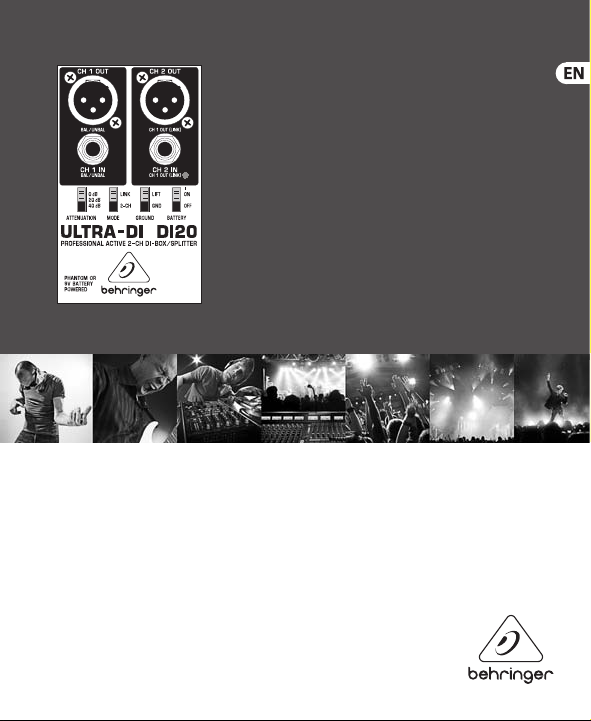
ULTRA-DI DI20
Professional Active 2-Channel DI-Box/Splitter
Page 2

2 ULTRA-DI DI20
Table of Contents
Thank you ............................................................................................................... 2
Warranty ................................................................................................................. 3
Legal Disclaimer .................................................................................................... 4
Limited warranty ................................................................................................... 5
1. Welcome to the BEHR INGER Family! ............................................................... 6
2. Contr ols .............................................................................................................. 6
3. Connection Options .......................................................................................... 8
3.1 Connecting a (bass)guitar .............................................................................................. 8
3.2 Converting output signals of a keyboard, DJ-mixer, etc. ........................................ 9
4. Audio Connections ........................................................................................... 9
5. Multilingual Documentation ..........................................................................11
6. Specications ...................................................................................................11
Thank you
Thank you f or the conden ce you have placed i n us
by purcha sing the ULTRA-D I DI20 profess ional activ e
2-channel DI-box/splitter.
Page 3
3 ULTRA-DI DI20
Caution
Warranty
Terminals marked with this symbol carry
electrical current of sucient magnitude
to consti tute risk of elec tric shock. Us e only
high-quality professio nal speaker cables with
¼" TS or twist-l ocking plugs pr e-installed .
Allother installation or modication should be
perfo rmed only by quali edpersonnel .
This symbol, wherever it appears,
alert syou to the presence o f
uninsulated dangerous voltage
inside the e nclosure-voltag e that may be
sucien t to constitute a ri sk ofshock.
This symbol, wherever it appears,
alertsyou to important operating
and maintenance instructions in
the accompanying literature. Please read
themanual.
Caution
To reduce the ris k of electric sh ock,
donot remove t he top cover
(orthe rear sec tion). No user ser viceable part s
inside. Refer servicing to qualied personnel.
To reduce the ris k of re or
appliance t o rain and moistur e. The apparatus
shall not be e xposed to dripp ing or splashing
liquids and no objects lled with liquids,
suchas vas es, shall be placed on t he apparatus.
person nel only. Toreduce the risk of e lectric
shock do not perform any servicing other than
that contained in the operation instructions.
Repairs h ave to be perfor med by qualied
servicepersonnel.
1. Read these instructions.
2. Keep these instructions.
3. Heed all warnings.
4. Follow all instruc tions.
5. Do not u se this apparatu s near water.
6. Clean onl y with dry clot h.
7. Do not bloc k any ventilation
openings. Install in accordance with the
manufacturer ’sinstructions.
8. Do not ins tall near any heat sou rces
such as rad iators, heat regi sters, stoves,
orother apparatus (including ampliers)
thatprod uceheat.
elect ric shock, do not e xpose this
Caution
These service instruc tions are
for use by qu alied servi ce
Page 4
4 ULTRA-DI DI20
9. D o not defeat the sa fety purpos e of the
normally, orha s beendropped.
15. The a pparatus shall b e connected to a
polarized or grounding-type plug. A polarized
plug has t wo blades with one w ider than the
other. A groun ding-type plu g has two blades
and a third grounding prong. The wide blade
or the thir d prong are provid ed for your safet y.
Ifthe prov ided plug does not t into your
outlet, c onsult an elect rician for repla cement of
the obsolete outlet.
10.
Protec t the power cord fr om being
walked on or pi nched parti cularly at plugs,
convenience receptacles, and the point where
they exit f rom the appara tus.
11.
Use only attachments/accessories
specied by themanufacturer.
moving the cart/apparatus combination to
avoid injury from tip-over.
13. Unplug this apparatus during lightning
storms or when unused for long periods
oftime.
14. Refer all ser vicing to qualied service
personnel. Servicing is required when the
apparat us has been damage d in any way,
suchas powe r supply cord or plug i s damaged,
liquid has b een spilled or obje cts have fallen
into the app aratus, the appa ratus has been
expose d to rain or moistu re, does not operat e
12. Use only with the
cart, stand, tripod, bracket,
or table sp ecied by the
manufac turer, orsold with
the appar atus. When a car t
is used, us e caution when
MAINS socket outlet with a protective
earthingconnection.
16. Where the
MAINS plug or a n
appliance coupler is used
as the disconnect device,
thediscon nect device sha ll
remain readilyoperable.
LEGAL DISCLAIMER
TECHNICAL SPECI FIC ATIONS AND
APPEARANCE S ARE SUBJECT TO CHANGE
WITHOUT NOTICE AND ACCURAC Y IS NOT
GUARANTEED. BEHRINGER, KL ARKTEKNIK,
MIDA S, BUGERA, AND TURBOSOUND
ARE PART OF THE MUSIC GR OUP
MU SI C GROU P.C OM. AL L TRADEMARKS
ARE THE PROPERT Y OF THEIR RESPECTIVE
OWNERS. MUSI CGROUP ACCEPTS NO
LIABILIT Y FOR ANY LOSS WHICH MAY BE
SUFFERED BY ANY P ERSON WHO RELIES
EITHER WHO LLY OR IN PAR T UPON ANY
DESCRIPTION, PH OTOGRAPH OR STATE MENT
CONTAINED HERE IN. COLORS AND
SPECI FICAT IONS MAY VARY FROM ACTUAL
PRODUCT. MUSIC GROUP PRODUCTS ARE
SOLD THROUGH AUTHO RIZED FULLFILLERS
AND RE SELLERS ONLY. F ULLFILLERSAND
RESELLER S ARE NOT AGENTS OF
MUSICGROUP AND HAVE ABS OLUTELY
NO AUTHORITY TO B IND MUSICGRO UP BY
Page 5

5 ULTRA-DI DI20
ANY EXPRE SS OR IMPLIED UNDERTAKING
OR REPRE SENTATION. THIS MA NUAL IS
COPYRIG HTED. NO PART OF TH IS MANUA L
MAY BE REPRODUCED OR TR ANSMITTED IN
ANY FORM OR BY ANY ME ANS, ELECTRONIC
OR MECHANICAL , INCLUDING PHOTOCOPY ING
AND RECORDING O F ANY KIND, FOR ANY
PURPOSE, WITHO UT THE EXPRESS WRITTEN
PERMISSION O F MUSICGROUPIPLTD.
ALL RIGHTS RESERVED.
© 2013 MUSICGroupIPLtd.
Trident Chambers, Wickhams Cay,
P.O. Box 146, R oad Town, Tortola,
BritishVirgin Islands
LIMITED WARRANTY
For the applicable warranty terms and
conditions and additional information
regardi ng MUSIC Group ’s Limited Warranty,
please se e complete detai ls online at
www.music-group.com/warranty.
Page 6

6 ULTRA-DI DI20
1. Welcome to the BEHRINGER Family!
On stage a s well as in studios, i t is sometimes
advantageous to connect certain sound
sources d irectly to the mi xing console.
Sincemany instruments (keyboards,
forexamp le) don’thave balanced ou tputs
they requ ire a DI-box. Some times,
evenguita rs can’t be direc tly connecte d to
mixing con soles because t heir impedance is
too high.
By using a DI- box, you can direc tly tap into
a high-impedance, unbalanced signal—
forexamp le, a signal betwee n a guitar and a
guitar am plier. From this point , you can feed
this signal d irectly to a mix ing console.
There are active and passive DI-boxes. A passive
DI-box is more aordable, but its performance
is dependent on the impedance of the device
to which it is connected. When the impedance
on the mixing console’s end changes, so does
the impedance at the input of the DI-box.
Such DI-boxes only function properly when
the connected impedance values are strictly
specied (high at the input, low at the output).
Active DI-boxes are not aected by these
impedance considerations. The input impedance
of the DI20 is extremely high, and it absolutely
does not inuence the signal ow through the
DI-box. The output impedance is balanced and
always very low, whereby the signal is far less
prone to being aected by noise.
◊ To prevent damaging your
loudspeakers, first connect the
DI-box and t hen hook up the
respective channel. The same goes
for alternating between battery and
phantom power operating modes.
2. Controls
®
N11999
Fig. 2.1: Contro ls of the DI20
Page 7

7 ULTRA-DI DI20
(1) CH. 1 IN input is u sed to connect
unbalance d as well as balanced sig nal
sources to c hannel 1.
(2) CH.1 OUT is the balanced out put at mic
level for ch annel 1.
(3) CH.2 IN inpu t is used to connec t
unbalance d as well as balanced sig nal
sources to c hannel 2. In Link mode
(see(6)) this co nnector func tions as
output an d sends the signal
direc tly from channel 1.
(4) CH. 2 OUT is the ba lanced output at
mic level fo r channel 2. In Link Mode
(see(6)) this co nnector sends t he signal
direc tly from channel 1.
(5) The ATTENUATION dampening switch
considerably increases the useful
operati ng range of the DI20 fr om low
signal levels of a high-impendence
microph one or a guitar, all the way
to the speake r connectors of a g uitar
amplier (s olid state). You can
selec t between 20 and 40 d B worth
ofattenuation.
◊ You should on ly use the ATTENUATION
switch w hen your DI20 rather t han
the mixing console preamp begins
distorting. Otherwise refrain
from us ing this func tion to avoid
excessive dampening.
(6) The MODE switc h lets you selec t the
operati ng modes of the DI20. In th e
2-CH mode, t wo independent sig nals
can be conn ected to channel s 1 and 2
respec tively. In LINK mode the DI- box
funct ions as a splitter : One signal can
be fed to the c hannel 1 input and spl it
into two ba lanced signals (at outp uts
1 and 2) and an unba lanced signal
at CH.1 OUT. The un-balanc ed signal
can, forex ample, be connec ted to an
additional amplier.
◊ When connecting a tube amplifier
to the inpu t of the DI20, please keep
in mind tha t an appropria te load
resist ance (e. g. a loudspeak er)
must be co nnected to the CH.1 OUT
(LINK MODE) con nector.
(7) The BAT TERY sw itch activate s the
batter y powered mode. Se t the battery
operati ng mode to OFF when your
DI20 is connec ted to phantom powe r.
While set ting it to OFF, brief whist ling
noise may occ ur. This is completely
normal and needs no further attention.
However, you should not change the
batter y switch when you h ave an amp
connected. For battery operation,
you’llonl y need a commercial 9 V
batter y of the 6LR61 type.
Page 8

8 ULTRA-DI DI20
(8) By using th e GROUND switch, y ou can
interrupt (LIFT) the grounding between
the input an d output. Depen ding on
how other de vices connecte d to your
DI-box are grounded, ground loops can
be eliminated.
◊ Never conn ect pin 2 or pin 3 to pi n 1!
Never remo ve the screen pro tection
on pin 1. Othe rwise, you won’t b e able
to run the DI20 o n phantom power
(for examp le, phantom power f rom a
mixing console).
Battery compartment
To access the bat tery compar tment,
loosenth e screw on the rear.
3. Connection Options
3.1 Connecting a (bass)guitar
Out
In
ULTRA-DI DI20
Link Out
EURORACK
UB2222FX-PRO
Fig. 3.1: Guitar ➠ DI-box ➠ guitar amp/mixing console
This illus tration shows the s tandard
applica tion of a DI-box. The s ignal is fed
unbalance d to a guitar amp and bala nced to a
mixing console (LINK mode). This application
has advant ages when used wi th bass guitars ,
becaus e very few microp hones are able to
pick up low f requencies at hig h levels.
Page 9

9 ULTRA-DI DI20
3.2 Converting output signals of a keyboard, DJ-mixer, etc.
L
R InIn
PRO MIXER
VMX200
Out
Out
ULTRA-DI
DI20
Mic In
4. Audio Connections
The BEHRINGE R ULTRA-D I DI20 features
electronically servo -balanced standard inputs
and outpu ts. The circuit d esign is equippe d
with auto matic hum suppress ion for balanced
signals and o perates problem -free even at
high levels. Externally induced mains hum
is thus ec iently suppress ed. The servo
function automatically detect s unbalanced
pin connections and changes the nominal
level inter nally by 6 dB so that ther e is
no diere nce in level betwe en input and
outputsi gnals.
Balanced use with XLR connectors
EURORACK UB2222FX-PRO
Fig. 3.2: DJ -mixer ➠ DI-box ➠ mixing console
This conguration is recommended when
using a DJ-mixer or another signal source,
which sends an unbalanced line level signal.
In additio n, if you need a separ ate monitor
signal, the li ne level signal can be s ent to
another amplier.
12
3
input
1 = ground/shield
2 = hot (+ve)
3 = cold (-ve)
For unbalanced use, pin 1 and pin 3
have to be bridged
Fig. 4.1: XLR conne ctors
output
1
2
3
Page 10

10 ULTRA-DI DI20
Unbalanced ¼" TS connector
strain relief clamp
sleeve
tip
sleeve
(ground/shield)
tip
(signal)
Fig. 4.2: ¼" TS co nnector
Balanced ¼" TRS connector
strain relief clamp
sleeve
ring
tip
sleeve
ground/shield
ring
cold (-ve)
tip
hot (+ve)
For connection of balanced and
unbalanced plugs, ring and sleeve
have to be bridged at the stereo plug.
Fig. 4.3: ¼" TRS c onnector
Page 11

11 ULTRA-DI DI20
5. Multilingual Documentation
◊ The following versions of this user’s
manual can be downloaded free
of charge at http://behringer.com:
German, French, Spanish, Italian,
Dutch, Finnish, Swedish, Danish,
Portuguese and Greek.
6. Specications
Frequenc y response 10 Hz to 70 kHz (-3 dB)
Noise 100 dBu
Distor tion < 0.014% (1 kHz, 0 dBu in)
Input resi stance > 250 kΩ
Connec tion impedance > 600 Ω
Input ¼" mon o jack
Output XLR balanced
Max. inpu t level +12/+32/+52 dBu
Phantom powe r 18 V DC to 48 V DC
Batter y power 9 V 6LR91
Dimensio ns approx. 6 x 5 x 2 ⁄"
Weight approx. 240 g
BEHRIN GER is const antly str iving to ma intain the hi ghest pr ofessio nal standa rds. As a res ult of thes e effor ts, modi ficati ons may be mad e from
time to tim e to exist ing produ cts wit hout prio r notice. Spe cifica tions and ap pearance m ay theref ore diff er from th ose liste d or shown.
approx. 150 x 130 x 60 mm
Page 12

We Hear You
 Loading...