

Page 1
1 ULTRA-DI DI100 User Manual
User Manual
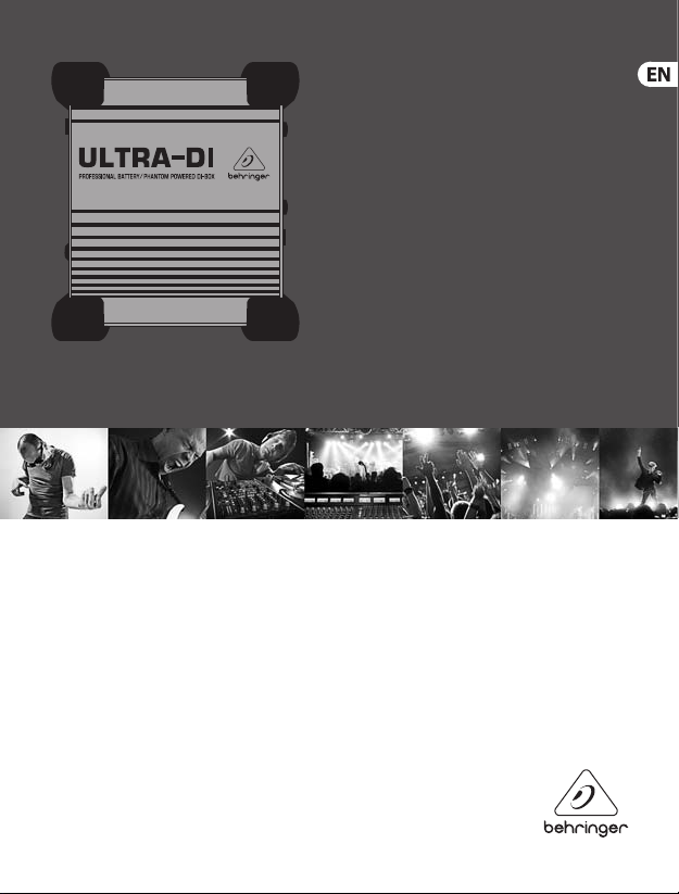
ULTRA-DI DI100
Professional Battery/Phantom Powered DI-Box
Page 2

2 ULTRA-DI DI100 User Manual
Table of Contents
Thank you ................................................................................. 2
1. Control Elements ................................................................. 7
2. DI100 Congurations .......................................................... 8
2.1 Tapping signal from the (Bass) guitar ...................................... 8
2.2 Converting the output of a Keyboard / DJ-mixer /
Headphone plug ..................................................................................... 9
2.3 Converting a microphone from high impedance
unbalanced to low impedancebalanced .................................... 10
2.4 Tapping a signal from a power amplieroutput .............. 10
3. Specications......................................................................11
Thank you
Thank you very much for expressing your condence in Behringer products by
purchasing the ULTRA-DI.
Page 3
3 ULTRA-DI DI100 User Manual
Important Safety
Instructions
Terminals marked with this
symbol c arry electric al current of
sucient magnitude to
constitu te risk of electric sho ck. Use only
high-quality prof essional speaker cables with
¼" TS or twist-lock ing plugs pre-inst alled.
Allother installation or modication should be
perfo rmed only by qualiedper sonnel.
This symbol, wherever it appears,
alerts yo u to the presence of
uninsulated dangerous voltage
inside the encl osure - voltage that may be
sucient to con stitute a risk ofshock .
This symbol, wherever it appears,
alerts you to important operating
and maintenance instructions in
the accompanying literature. Please read
themanual.
Caution
To reduce the risk of ele ctric
shock, do not r emove the
top cover (or the rear sec tion). No user
serviceable part s inside. Refer servicing to
qualiedpersonnel.
Caution
To reduce the risk of re o r
electr ic shock, do not expos e this
appliance to rai n and moisture. Theapparat us
shall not be exp osed to dripping or splash ing
liquids and no objects lled with liquids, such
as vases, shall b e placed on the apparatus.
Caution
These service instruc tions are
for use by quali ed service
personne l only. Toreduce the risk of el ectric
shock do not perform any servicing other than
that contained in the operation instructions.
Repairshave to b e performed by quali ed
servicepersonnel.
1. Read these instructions.
2. Keep these instructions.
3. Heed all warnings.
4. Follow all instructions.
5. Do not use this appar atus nearwater.
6. Clean only with dry clot h.
7. Do not block any ve ntilation
openings. Install in accordance with the
manufacturer’sinstructions.
8. Do not install near any heat sou rces
such as radiato rs, heat registers, s toves,
orother apparatus (including ampliers)
thatproduceheat.
Page 4
4 ULTRA-DI DI100 User Manual
9. Do not defeat the sa fety purpose of th e
polarized o r grounding-type plu g. Apolarized
plug has two bl ades with one wider than the
other. A grounding -type plug has two blad es
and a third grounding prong. The wide blade
or the third pr ong are provided for your s afety.
Ifthe provide d plug does not t into your
outlet, consult an electric ian for replacement
of the obsole teoutlet.
10. Protect the power cord f rom being
walked on or pinc hed particularly at p lugs,
convenience receptacles, and the point where
they exit f rom theapparatus.
11. Use only attachments/accessories
specied b y themanufacturer.
12. Use only with
the cart , stand, tripod,
bracket, ort able
specied b y the
manufac turer, orsold
with the apparatus.
When a car t is used, usecaution wh en moving
the cart/apparatus combination to avoid injury
from tip -over.
13. Unplug this apparatus during lightning
storms or when unused for long periods
oftime.
14. Refer all servicing to qualied service
personnel. Servicing is required when the
apparatus ha s been damaged in any way,
such as power sup ply cord or plug is damaged,
liquid has been s pilled or objects have f allen
into the appar atus, the apparatus has be en
expose d to rain or moisture, does not o perate
normally, orhas bee ndropped.
15. The app aratus shall be connecte d to
a MAINS socket ou tlet with a protect ive
earthingconnection.
16. Where th e MAINS plug or
an appliance coup ler is used as
the disconnect device,
thedisconne ct device shall
remain readilyoperable.
LEGAL DISCLAIMER
TECHNICAL SPECIFICATIONS AND
APPEARANCES ARE SUBJECT TO CHANGE
WITHOUT NOTICE AND ACCURACY IS NOT
GUARANTEED. BEHRINGER, KLARKTEKNIK,
MIDAS, BUGERA, ANDTURBOSOUND
ARE PART OF TH E MUSIC GROUP MUSIC
GROUP.COM. ALL TRADEMAR KS ARE THE
PROPER TY OF THEIR RESPECTI VE OWNERS.
MUSICGRO UP ACCEPTS NO LIABILITY FOR
ANY LOSS WH ICH MAY BE SUFFERED BY
ANY PERSON WHO RELIES EITHER WHOLLY
OR IN PART UPO N ANY DESCRIP TION,
PHOTOGRAPH OR STATEMENT CONTAINED
HEREIN. COLORSAND SPECIFICATIONS
MAY VARY FROM ACT UAL PRODUCT. MUSIC
GROUP PRODUCTS ARE SOLD THROUGH
AUTHORIZED FULLFILLERS AND RESELLERS
ONLY. FULLFILLERS AND RESELLERS ARE
NOT AGENT S OF MUSICGROUP AND HAVE
ABSOLUTELY NO AUTHORITY TO BIND
MUSICGRO UP BY ANY EXPRE SS OR IMPLIED
UNDERTAKING OR REPRESENTATION. THIS
MANUAL IS COPYRIGHTED. NO PART OF
THIS MAN UAL MAY BE REPRODUCED OR
Page 5

5 ULTRA-DI DI100 User Manual
TRANS MITTED IN ANY FORM OR BY ANY
MEANS, ELECTRONIC OR MECHANICAL,
INCLUDING PHOTOCOPYING AND RECORDING
OF ANY KIND, FORANY PURPOSE, WITHOUT
THE EXPRESS WRIT TEN PERMISSION OF
MUSICGRO UPIPLTD.
ALL RIGHTS RESERVED.
© 2013 MUSICGRO UPIPLTD.
TRIDENT CHAMBERS, WICKHAMS CAY,
P.O. BOX 146, ROAD TOWN, TORTOLA,
BRITISHVIRGIN ISLANDS
LIMITED WARRANTY
For the applic able warranty terms a nd
conditions and additional information
regarding MUSIC Gr oup’s Limited Warranty,
please see co mplete details online at
www.music-group.com/warranty.
Page 6

6 ULTRA-DI DI100 User Manual
Welcome to BEHRINGER!
DI stands fo r Direct Inject ion. On stage or in the st udio there are sources you w ant to connect to your
mixer that are not e quipped with a suita ble connection. Keybo ards seldom have properl y balanced
outputs . Guitars cannot be di rectly plugged into a m ixer and placing a micropho ne in front of
a backline is not always ideal. A microphone picks up ambient noise such as other instruments.
Lowfrequen cies (such as from a bass gui tar) are especially dic ult for a microphone to hand le.
A DI-box makes it p ossible to tap a signal from a high impedance unbalanced line, for instance
the signal from a guitar to a guitar amplier, and injec t it directly into the mixer’s input
without having to use a microphone. But that’s not all, there are lots of situations where you
want to injec t the signal coming from an unbalanced source dire ctly into your mixer and
preferably balanced, too. Thatisthe application of a Direct Injection box.
Impedance is the electric al frequency dependent resistance of a device combined with its
phase response. It is a literally complex matter. That is why a good DI-box is dis tinguishable
from a bad one. A s with a power amplier and speakers the impedance to a device determines
the perf ormance. With a good power ampli er the load impedance only aects the ma ximum
power output. Whereason some ot her devices the impedance governs other properties as well.
With a trans former as used in a DI-box, the connected impedances (in and out) inuencethe
bandwidth, frequenc y response, distortion, etc.
There are t wo basic types of DI-b oxes, passive and active. Bot h active and passive DI boxe s are
designed to b e connected to the consol e’s microphone i nput. Apassive DI box has the adv antage
of being slight ly lower in cost (lesselec tronics, no batter y facility) but their p erformance is highl y
dependent on t he connected impedan ces. When the impedance on th e mixer side of a passive
DI-box chang es, the impedance on the inpu t changes also. Notonly that, the f requency respon se
changes, too. A p assive DI-box only works we ll at specied connec ted impedances, high in and
low out, which m eans that they only work in a sta ndardapplication.
Active DI-boxes don’t have such restrictions. The signal coming from the input is buered
with an amplier. The input impedance of the ULTRA-DI is ultra-high so it doesn’t aect
the signal throughput at all. The output impedance of the Ultra-DI is b alanced and very low
so that it is much less susceptible to picking up hum and noise. This way, the impedance
for the signal source is independent from the impedance of the used mixer and vice vers a.
There is no sound alteration. The t ransformer used is BEHRINGER´s renowned OT-1 witch
guarantees distortion free, clean soun d and a at frequency response. Furthermore the
BEHRINGER ULTRA-DI can be powered by your console’s phantom power or by battery and
switches au tomatically between these two.
Page 7

7 ULTRA-DI DI100 User Manual
◊ To avoid switching noise, you should mute the desk channel before activating
the DI100. Same applies when switc hing between batte ry and phantom power
and vice versa.
The design of the DI100 includes four sturdy rubber feet which protect the unit
(even during a unplanne d drop) and allow cables to run under neath. Italsoprovides liter ally
a “ground lift ” so that the unit can be stacked on top ofanot her unit and other equipment
without creating ground loops.
1. Control Elements
(1)
(2) (3) (4)
(7) (6) (8)
Fig 1.1: Front & Rear DI100
(1) With the ON/OFF switch you can switch the b attery power on and o to preserve
batter y life. Switched o the ultra-di will still work on phantom power. Switchedon,
the ULTRA-DI will automatically switch between battery and phantom power. When the
DI100 is operating on battery power the on/o LED will ash once every few seconds,
when operating on phantom power the LED will light up continuously.
(2) INPUT. Connect the source to this ¼" jack to receive the signal.
(3) To provide maximum exibility the ULTRA-DI is also t ted with an unbalanced XLR input
to connect t he source.
(4) LINK OUT. This is the unbalanced parallel output of the ULTRA-DI. Connec tthis to the
input of the backline or monitor amplier.
◊ The ¼" jacks (input and link out) and the Input XLR are wir ed parallel, so any
connection as input will give the same performance.
(5) The -20 dB attenuation switches greatly increase the operating range of the ULTRA-DI.
From the low-level signals of a high impedance microphone or guitar to the hot speaker
terminals of a P. A. amplier. Depressing both will give 40 dB attenuation.
(5)
Page 8

8 ULTRA-DI DI100 User Manual
◊ Only use the -20 dB switches if you are sure the ULT RA-D I is clipping (overloading)
and not your mic pre-amp. Always use as little attenuation as possible to get the
best possible signal-to-noise ratio.
(6) OUTPUT. This is the balanced microphone level output of the ULTRA-DI. Connection to
the microphone input should be made with a standard high qualit y balanced cable.
◊ Never connec t pin 2 or 3 to pin 1 and never disconnect the shield from pin 1,
or the unit will not work on phantom power.
(7) Use the GROUND LIFT switch to either connect the ground of input and output or
keep them completely separate. Depending on the grounding of the connected devices
linking or disconnecting will reduce hum or prevent ground loops. GROUND LIFT ON
means no interconnection.
(8) BATTERY COMPARTMENT. Loosen the screw to open the compartment and to replace
the 9V batter y. When the ULTRA-DI is s witched on batter y power the LED blinks, when it
stops blinking it is time to change the batter y.
2. DI100 Congurations
The next section will show several dierent ways the ULTRA-DI can be hooked up.
2.1 Tapping signal from the (Bass) guitar
Microphone Input
Out
In
DI100
Fig 2.1: Guitar ➟ DI ➟ Guitar Amp/Mixerv
Link
Out
Page 9

9 ULTRA-DI DI100 User Manual
This gure shows the standard application of any direct injec tion box. The signal to the
amplier is unaected, it is just tapped o to be routed to the mic rophone input of the mixer.
Especially bass guitars benet from this application. It is dicult to nd a microphone which
handles high leve l low frequencies well and with a linear frequency response. Using the
ULTRA-DI will give you c lean and crisp sound. Connec t the ULTRA-DI after any eects device s
so that their e ect will be heard over the P.A.-system or on the recording. If t he mixer provides
phantom power between 20 V and 52 V, the internal battery of the DI100 will automatically be
detached. You should chose this possibility whenever possible to save battery power.
2.2 Converting the output of a Keyboard / DJ-mixer / Headphone plug
In Out
L
In
R
Fig 2.2: DJ- mixer ➟ 2 x DI ➟ mixer
To Monitor
Out
Microphone
Inputs panned
Left & Right
This conguration can be used with a keyboard, DJ- mixer, headphone output, drum kit or
any (stereo or mono) line source. In all cases where you want to run long lines, for inst ance
to the FOH (Front Of House) desk. In most cases the bes t setting is achieved by depressing
one of the -20 dB pad buttons to avoid overloading the FOH desk input. The signal can be
linked through to another amplier, if the keyboard player / DJ / etc. wants to have a monitor
connecte d independent of the foldback mix. The ULTRA-DI ac ts as both a ground isolator and
an unbalanced to balanced converter.
Page 10

10 ULTRA-DI DI100 User Manual
2.3 Converting a microphone from high impedance
unbalanced to low impedancebalanced
Sometimes all that’s available (especially when all other mics are in use) is a unbalanced high
impedance mic rophone with an unbalanced jack. With the ULTRA-DI long cable runs to the
console can be established without fear of picking up noise and hum. Just plug the jack into the
input and conne ct the output to the console’s mic in.
2.4 Tapping a signal from a power amplieroutput
When no line out is available it is possible to connect an amplier outpu t directly to the DI100
(for example, recording direc t from a guitar amplier, TV-speaker, etc). It is possible to connec t
the output, i.e an extra speaker output, of up to 3000 Watts to the ULTRA-DI without fear of
overloading. Pay attention to the t wo -20 dB buttons on t he ULTRA-DI! Both must be depress ed
if an amplier output is connec ted to the DI100 input.
+ Red or positive post
- Black or negative post
Fig 2.3: Conne ction to an am plier outp ut
To DI100 input
◊ Always make sure the ground lift is on (no grou nd link) when connecting to speaker
terminals. This prevents accidental short-circuiting of the amplifier output.
Also make sure the Tip of the inpu t jack is connected to the red terminal and that
the metal housing of the DI100 has no co ntact with other equipment.
Page 11

11 ULTRA-DI DI100 User Manual
3. Specications
Frequency Response 10 Hz to 93 kHz
Noise Level -110 dBu
THD + N @ 1 kHz / 0 dBu < 0,005 %
Input Impedance > 250 kOhm
Load Impedance > 600 Ohm
Inputs ¼" jack unbal.
In/Link Out XLR unbalanced In
Output XLR balanced Out
Maximum Inpu t level +10/ +30/ +50 dBu
Power supply
Phantom power 18 V DC to 48 V DC
Batter y 9 V blockcell 6LR91
Dimensions 150 x 130 x 60 mm
Weight ca. 650 g
BEHRING ER is constant ly strivin g to maintain the h ighest prof essional st andards. As a r esult of thes e effor ts, modif ications may b e
made fro m time to time to ex isting pro ducts wit hout prior no tice. Specif ications an d appearance ma y differ f rom those lis ted or shown.
Page 12

We Hear You
 Loading...