

Page 1
Documentation | EN
EP3752-0000
2 x 3-axis accelerometers
2020-08-20 | Version: 1.2
Page 2

Page 3

Table of contents
Table of contents
1 Foreword ....................................................................................................................................................5
1.1 Notes on the documentation..............................................................................................................5
1.2 Safety instructions .............................................................................................................................6
1.3 Documentation issue status ..............................................................................................................7
2 EtherCAT Box - Introduction ....................................................................................................................8
3 Product overview.....................................................................................................................................10
3.1 Introduction......................................................................................................................................10
3.2 Technical data .................................................................................................................................11
3.3 Process image.................................................................................................................................13
4 Mounting and cabling..............................................................................................................................14
4.1 Mounting..........................................................................................................................................14
4.1.1 Dimensions ...................................................................................................................... 14
4.1.2 Fixing ............................................................................................................................... 15
4.1.3 Nut torque for connectors ................................................................................................ 15
4.2 Supply voltages ...............................................................................................................................16
4.2.1 Connectors ...................................................................................................................... 16
4.2.2 Status LEDs..................................................................................................................... 17
4.2.3 Conductor losses ............................................................................................................. 17
4.3 EtherCAT.........................................................................................................................................18
4.3.1 Connectors ...................................................................................................................... 18
4.3.2 Status LEDs..................................................................................................................... 19
4.3.3 Cables.............................................................................................................................. 19
4.4 UL Requirements.............................................................................................................................20
5 Commissioning/Configuration ...............................................................................................................21
5.1 Integration in TwinCAT ....................................................................................................................21
5.2 Acceleration sensors .......................................................................................................................22
5.2.1 Settings............................................................................................................................ 23
5.2.2 Filter................................................................................................................................. 25
5.2.3 Inclination measurement.................................................................................................. 26
5.3 Restoring the delivery state .............................................................................................................28
5.4 Decommissioning ............................................................................................................................29
6 CoE parameters .......................................................................................................................................30
6.1 Object overview ...............................................................................................................................30
6.2 Object description and parameterization .........................................................................................34
7 Appendix ..................................................................................................................................................45
7.1 General operating conditions...........................................................................................................45
7.2 Accessories .....................................................................................................................................46
7.3 Version identification of EtherCAT devices .....................................................................................47
7.3.1 Beckhoff Identification Code (BIC)................................................................................... 51
7.4 Support and Service ........................................................................................................................53
EP3752-0000 3Version: 1.2
Page 4

Table of contents
EP3752-00004 Version: 1.2
Page 5

Foreword
1 Foreword
1.1 Notes on the documentation
Intended audience
This description is only intended for the use of trained specialists in control and automation engineering who
are familiar with the applicable national standards.
It is essential that the documentation and the following notes and explanations are followed when installing
and commissioning these components.
It is the duty of the technical personnel to use the documentation published at the respective time of each
installation and commissioning.
The responsible staff must ensure that the application or use of the products described satisfy all the
requirements for safety, including all the relevant laws, regulations, guidelines and standards.
Disclaimer
The documentation has been prepared with care. The products described are, however, constantly under
development.
We reserve the right to revise and change the documentation at any time and without prior announcement.
No claims for the modification of products that have already been supplied may be made on the basis of the
data, diagrams and descriptions in this documentation.
Trademarks
Beckhoff®, TwinCAT®, EtherCAT®, EtherCATG®, EtherCATG10®, EtherCATP®, SafetyoverEtherCAT®,
TwinSAFE®, XFC®, XTS® and XPlanar® are registered trademarks of and licensed by Beckhoff Automation
GmbH. Other designations used in this publication may be trademarks whose use by third parties for their
own purposes could violate the rights of the owners.
Patent Pending
The EtherCAT Technology is covered, including but not limited to the following patent applications and
patents: EP1590927, EP1789857, EP1456722, EP2137893, DE102015105702 with corresponding
applications or registrations in various other countries.
EtherCAT® is registered trademark and patented technology, licensed by Beckhoff Automation GmbH,
Germany.
Copyright
© Beckhoff Automation GmbH & Co. KG, Germany.
The reproduction, distribution and utilization of this document as well as the communication of its contents to
others without express authorization are prohibited.
Offenders will be held liable for the payment of damages. All rights reserved in the event of the grant of a
patent, utility model or design.
EP3752-0000 5Version: 1.2
Page 6
Foreword
1.2 Safety instructions
Safety regulations
Please note the following safety instructions and explanations!
Product-specific safety instructions can be found on following pages or in the areas mounting, wiring,
commissioning etc.
Exclusion of liability
All the components are supplied in particular hardware and software configurations appropriate for the
application. Modifications to hardware or software configurations other than those described in the
documentation are not permitted, and nullify the liability of Beckhoff Automation GmbH & Co. KG.
Personnel qualification
This description is only intended for trained specialists in control, automation and drive engineering who are
familiar with the applicable national standards.
Description of instructions
In this documentation the following instructions are used.
These instructions must be read carefully and followed without fail!
DANGER
Serious risk of injury!
Failure to follow this safety instruction directly endangers the life and health of persons.
WARNING
Risk of injury!
Failure to follow this safety instruction endangers the life and health of persons.
CAUTION
Personal injuries!
Failure to follow this safety instruction can lead to injuries to persons.
NOTE
Damage to environment/equipment or data loss
Failure to follow this instruction can lead to environmental damage, equipment damage or data loss.
Tip or pointer
This symbol indicates information that contributes to better understanding.
EP3752-00006 Version: 1.2
Page 7

Foreword
1.3 Documentation issue status
Version Comment
1.2 • Technical data updated
• Structure update
1.1 • Corrections
• "Resolution" section added ("Technical data" chapter)
1.0 • First release
0.3 • Corrections
0.2 • Corrections
0.1 • First preliminary version
Firmware and hardware versions
This documentation refers to the firmware and hardware version that was applicable at the time the
documentation was written.
The module features are continuously improved and developed further. Modules having earlier production
statuses cannot have the same properties as modules with the latest status. However, existing properties
are retained and are not changed, so that older modules can always be replaced with new ones.
Documentation Firmware Hardware
1.2 02 05
1.1 02 03
1.0 01 02
The firmware and hardware version (delivery state) can be found in the batch number (D-number) printed on
the side of the EtherCAT Box.
Syntax of the batch number (D-number)
D: WW YY FF HH
WW - week of production (calendar week)
YY - year of production
FF - firmware version
HH - hardware version
Further information on this topic: Version identification of EtherCAT devices [}47].
Example with D no. 29 10 02 01:
29 - week of production 29
10 - year of production 2010
02 - firmware version 02
01 - hardware version 01
EP3752-0000 7Version: 1.2
Page 8
EtherCAT Box - Introduction
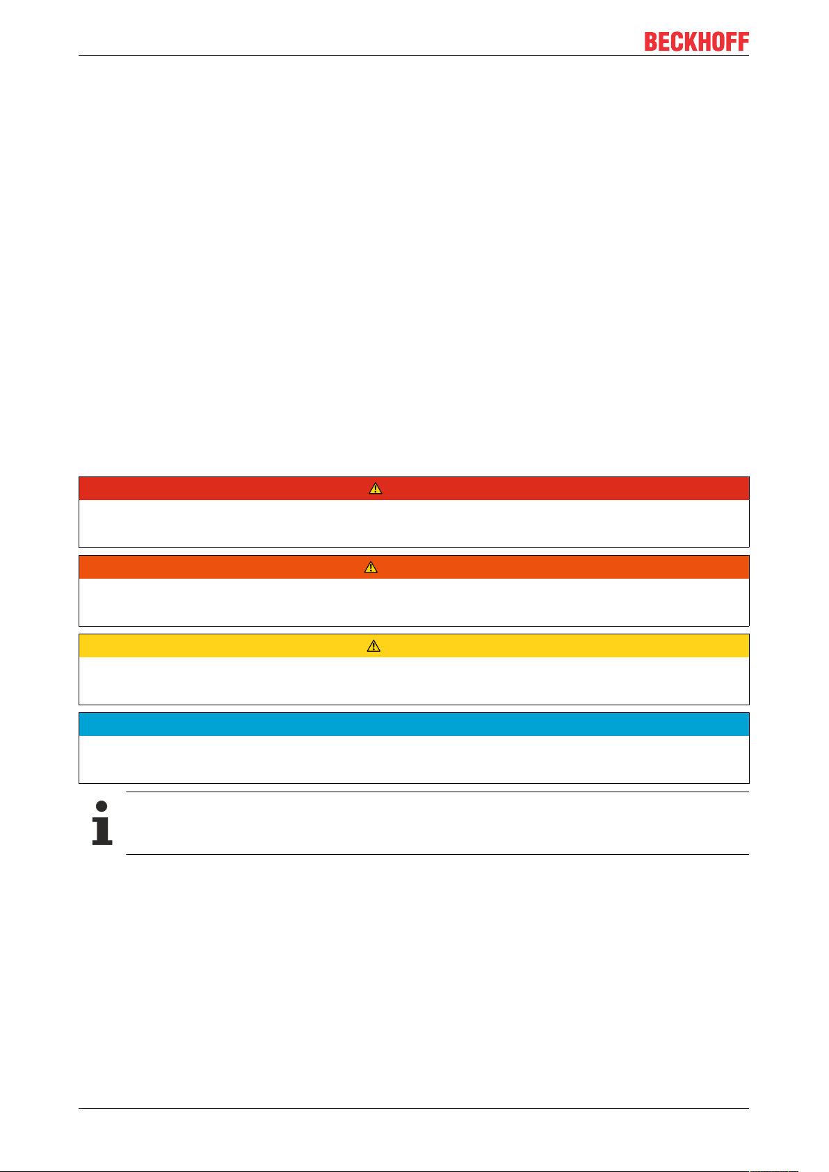
2 EtherCAT Box - Introduction
The EtherCAT system has been extended with EtherCAT Box modules with protection class IP67. Through
the integrated EtherCAT interface the modules can be connected directly to an EtherCAT network without an
additional Coupler Box. The high-performance of EtherCAT is thus maintained into each module.
The extremely low dimensions of only 126x30x26.5 mm (hxw xd) are identical to those of the Fieldbus
Box extension modules. They are thus particularly suitable for use where space is at a premium. The small
mass of the EtherCAT modules facilitates applications with mobile I/O interface (e.g. on a robot arm). The
EtherCAT connection is established via screened M8connectors.
Fig.1: EtherCAT Box Modules within an EtherCAT network
The robust design of the EtherCAT Box modules enables them to be used directly at the machine. Control
cabinets and terminal boxes are now no longer required. The modules are fully sealed and therefore ideally
prepared for wet, dirty or dusty conditions.
Pre-assembled cables significantly simplify EtherCAT and signal wiring. Very few wiring errors are made, so
that commissioning is optimized. In addition to pre-assembled EtherCAT, power and sensor cables, fieldconfigurable connectors and cables are available for maximum flexibility. Depending on the application, the
sensors and actuators are connected through M8 or M12connectors.
The EtherCAT modules cover the typical range of requirements for I/O signals with protection class IP67:
• digital inputs with different filters (3.0ms or 10μs)
• digital outputs with 0.5 or 2A output current
• analog inputs and outputs with 16bit resolution
• Thermocouple and RTD inputs
• Stepper motor modules
XFC (eXtreme Fast Control Technology) modules, including inputs with time stamp, are also available.
EP3752-00008 Version: 1.2
Page 9
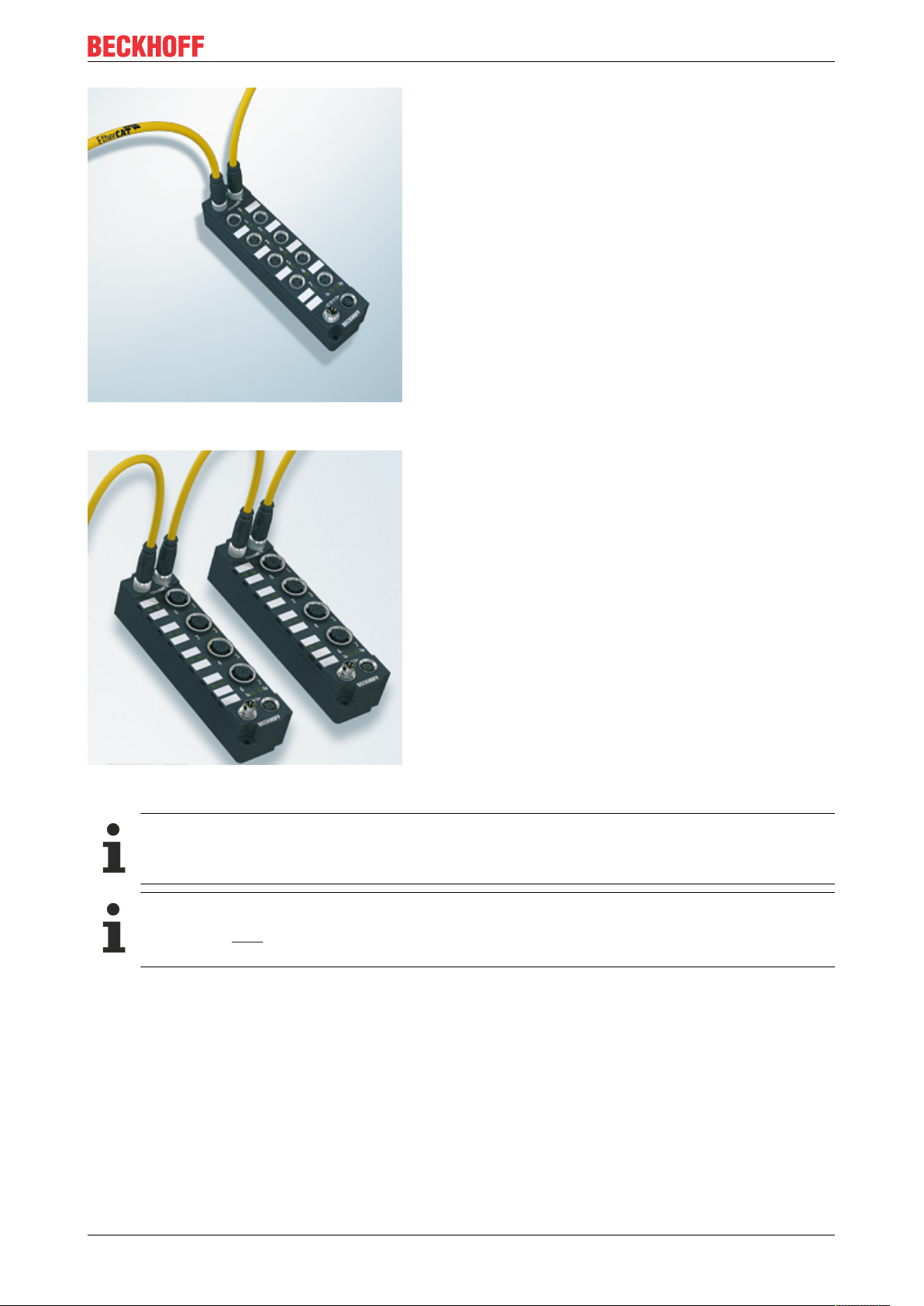
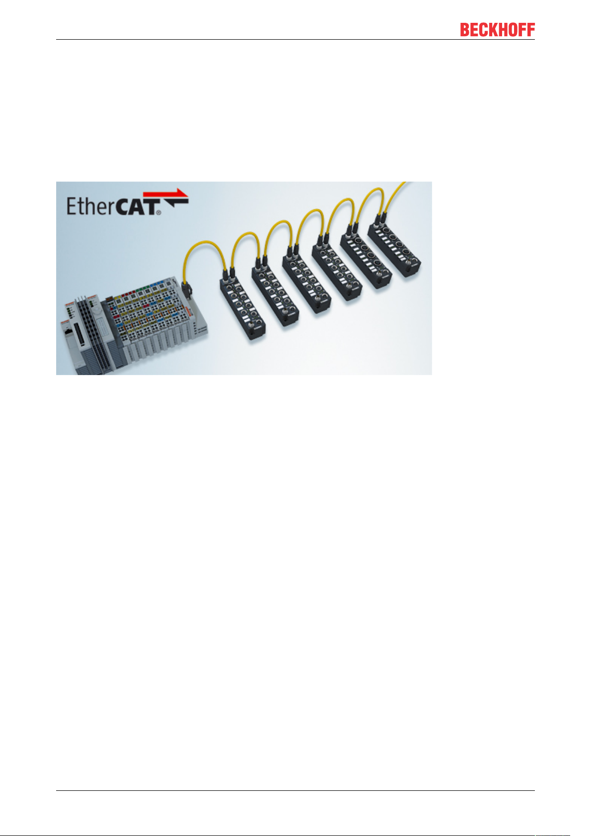
Fig.2: EtherCAT Box with M8 connections for sensors/actuators
EtherCAT Box - Introduction
Fig.3: EtherCAT Box with M12 connections for sensors/actuators
Basic EtherCAT documentation
You will find a detailed description of the EtherCAT system in the Basic System Documentation for
EtherCAT, which is available for download from our website (www.beckhoff.com) under Downloads.
EtherCAT XML Device Description
You will find XML files (XML Device Description Files) for Beckhoff EtherCAT modules on our website (www.beckhoff.com) under Downloads, in the Configuration Files area.
EP3752-0000 9Version: 1.2
Page 10
Product overview
3 Product overview
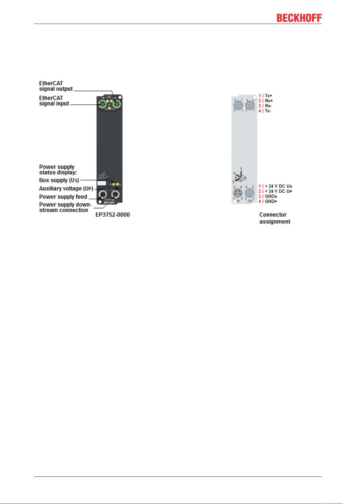
3.1 Introduction
2 x 3-axis accelerometers
The EP3752-0000 EtherCAT Box has two internal 3-axis accelerometers with 10-bit resolution and a
selectable measuring range of ±2 g, ±4 g, ±8 g and ±16 g. The maximum sampling rate is 5 kHz. The
measured values can be digitally filtered. Without filters the box operates cycle-synchronously.
Possible applications include the recording of vibrations and shocks/oscillations, but inclination
measurements in all three axes are also possible.
Through the measurement using sensors offset by 90°, the controller can carry out a plausibility check of the
data. Extended integrated filter functions enable the pre-processing and scaling of the acquired data in order
to filter out faults and relieve the controller.
EP3752-000010 Version: 1.2
Page 11

Product overview
3.2 Technical data
All values are typical values over the entire temperature range, unless stated otherwise.
Technical data EP3752-0000
Fieldbus
Fieldbus EtherCAT
Connection 2x M8 socket, 4-pin, green
Electrical isolation 500V (fieldbus/ IO)
Minimum cycle time 200µs
Distributed Clocks no
Supply voltages
Connection Input: 1 x M8 plug, 4-pin, black
Downstream connection: 1 x M8 socket, 4-pin, black
Control voltage U
Nominal voltage 24VDC (-15%/ +20%)
Sum current max. 4A
Current consumption from U
Peripheral voltage U
Nominal voltage 24VDC (-15%/ +20%)
Sum current max. 4A
Current consumption from U
Acceleration sensors
Sensor type Two 3-axis sensors / offset by 90°
Resolution1)
Representation
Measuring range
Sampling rate 200Hz to 5kHz
Environmental conditions
Ambient temperature
during operation
Ambient temperature
during storage
Vibration / shock resistance conforms to EN 60068-2-6 / EN 60068-2-27
EMC immunity / emission conforms to EN 61000-6-2 / EN 61000-6-4
Protection class IP65, IP66, IP67 conforms to EN 60529
Mechanics
Dimensions approx. 126x 30x 26.5mm (without connectors)
Weight approx. 165g
Installation position variable
Approvals and conformity
Approvals
S
S
P
P
2)
120mA
None. UP is only forwarded.
Measured values: 4mg (default)
Raw values: 10-bit (default)
1)
Measured values: 1mg/LSB
Raw values: 10-bit in 16-bit (left-aligned)
1)
±2g / ±4g / ±8g / ±16g selectively
-25 .. +60°C
-25 .. +55°C according to cURus
-40.. +85°C
CE, cURus [}20]
1)
Unit of measurement: 1g = 9.81m/s2 (acceleration of gravity). 1mg = 1/1000g.
2)
The resolution depends on the parameterization of the box. See section Resolution [}12].
EP3752-0000 11Version: 1.2
Page 12

Product overview
Resolution
The resolution of measured values and raw values depends on the parameters "Measuring range" and
"Sampling rate". The table below shows how these parameters influence the resolution:
Measuring range Sampling rate /
EtherCAT cycle time
±2g ≤1kHz /
±4g 8mg
±8g 16mg
±16g 48mg
±2g >1kHz /
±4g 32mg
±8g 64mg
±16g 192mg
The setting of the "Measuring range" and "Sampling rate" parameters is described in the chapter Settings
[}24].
Additional checks
The boxes have been subjected to the following checks:
Verification Explanation
Vibration 10 frequency sweeps in 3 axes
Shocks 1000 shocks in each direction, in 3 axes
≥1ms
<1ms
5Hz<f<60Hz displacement 0.35mm, constant amplitude
60.1Hz<f<500Hz acceleration 5g, constant amplitude
35g, 11ms
Raw values Measured values
10-bit 4mg
8-bit 16mg
Resolution
EP3752-000012 Version: 1.2
Page 13

3.3 Process image
The data for the two accelerometers can be found under AI Inputs Channel.
• Status Error: An error occurred during communication with the accelerometer.
• Value: 16-bit acceleration value
Product overview
The assignment of the process values to the sensor axes can be found in the chapter Acceleration sensors
[}22].
EP3752-0000 13Version: 1.2
Page 14
Mounting and cabling
119
126
23
3026.5
13.5
4 Mounting and cabling
4.1 Mounting
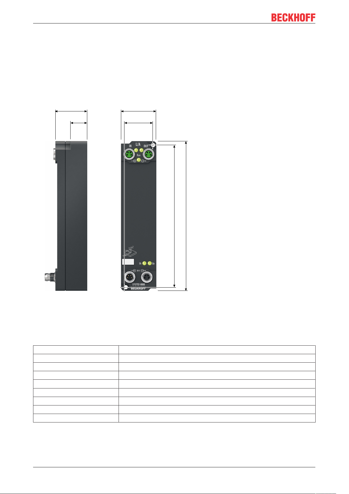
4.1.1 Dimensions
Fig.4: Dimensions
All dimensions are given in millimeters.
Housing features
Housing material PA6 (polyamide)
Sealing compound polyurethane
Mounting two fastening holes Ø 3.5 mm for M3
Metal parts brass, nickel-plated
Contacts CuZn, gold-plated
Installation position variable
Protection class IP65, IP66, IP67 (conforms to EN 60529) when screwed together
Dimensions (H x W x D) approx. 126 x 30 x 26.5 mm (without connectors)
Weight approx. 165g
EP3752-000014 Version: 1.2
Page 15

Mounting and cabling
4.1.2 Fixing
NOTE
Dirt during assembly
Dirty connectors can lead to malfunctions. Protection class IP67 can only be guaranteed if all cables and
connectors are connected.
• Protect the plug connectors against dirt during the assembly.
Mount the module with two M3 screws on the fastening holes in the corners of the module. The fastening
holes have no thread.
4.1.3 Nut torque for connectors
Screw M8 connectors tight with a torque wrench. (e.g. ZB8801 from Beckhoff)
Torque: 0.4Nm.
EP3752-0000 15Version: 1.2
Page 16
Mounting and cabling
Plug
Input
Socket
Forwarding
3 1
24
3 1
24
4.2 Supply voltages
The EtherCAT Box is supplied with two supply voltages. The supply voltages are electrically isolated in the
EtherCAT Box.
• Control voltage U
• Peripheral voltage U
S
P
Redirection of the supply voltages
The IN and OUT power connections are bridged in the module (not IP204x-Bxxx and IE204x). The supply
voltages US and UP can thus easily be transferred from EtherCATBox to EtherCATBox.
NOTE
Pay attention to the maximum permissible current!
Pay attention also for the redirection of the supply voltages US and UP, the maximum permissible current for
M8 connectors of 4A must not be exceeded!
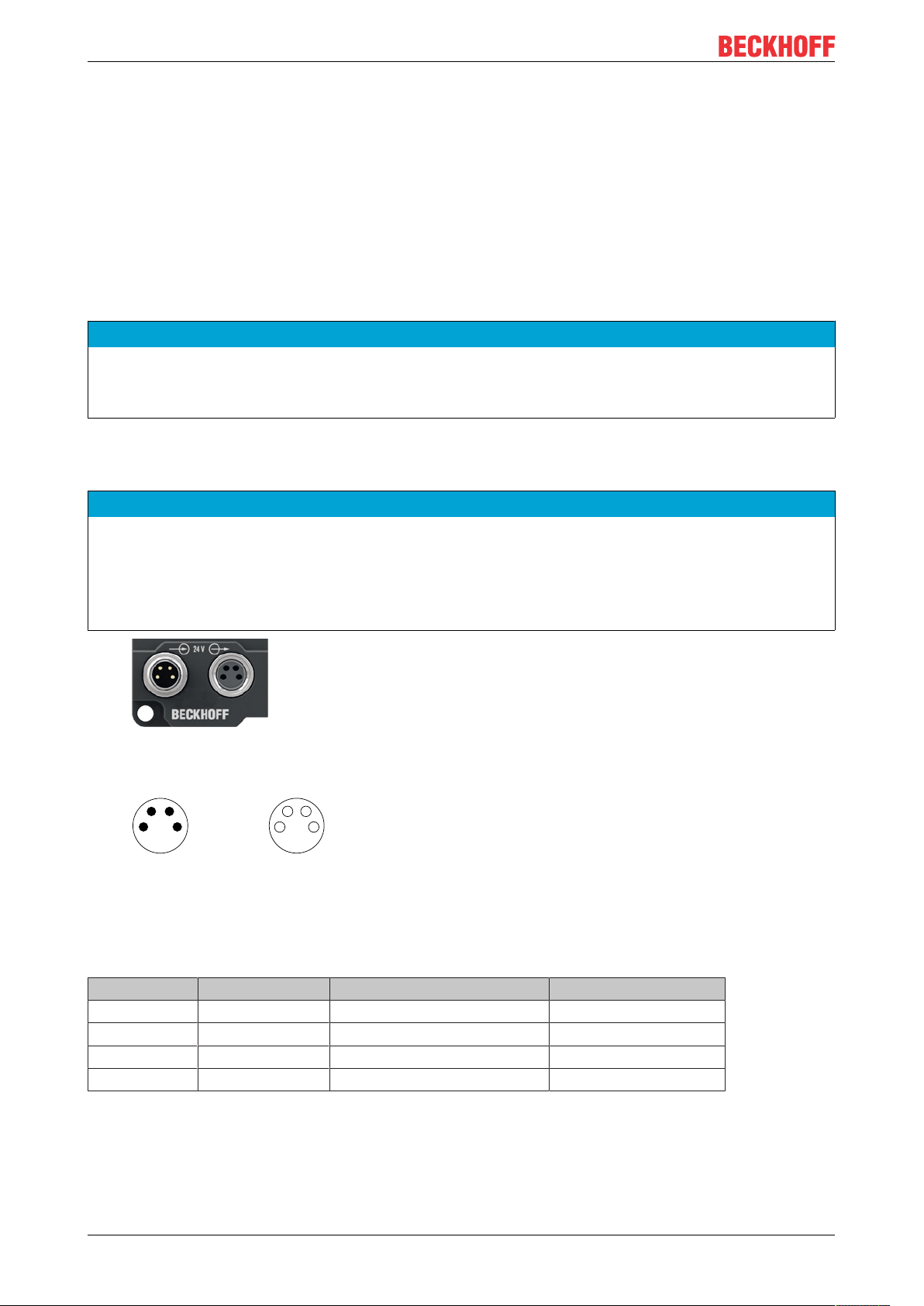
4.2.1 Connectors
NOTE
Risk of confusion: supply voltages and EtherCAT
Defect possible through incorrect insertion.
• Observe the color coding of the connectors:
black: Supply voltages
green: EtherCAT
Fig.5: Connectors for supply voltages
Fig.6: M8 connector
Contact Function Description Core color
1 U
2 U
3 GND
4 GND
1)
The core colors apply to cables of the type: Beckhoff ZK2020-3xxx-xxxx
S
P
S
P
Control voltage Brown
Peripheral voltage White
GND to U
GND to U
S
P
Blue
Black
1)
EP3752-000016 Version: 1.2
Page 17
Mounting and cabling
Vert. Faktor: 0,45 cm / V
5 10 15 20
2
4
6
8
10
250
0
12
30
Vert. Faktor: 0,45 cm / V
Voltage drop (V)
Cable length (m)
35
0,25 mm²
0,34 mm²
0,5 mm²
0,75 mm²
I = 2 A
Vert. Faktor: 0,45 cm / V
5 10 15 20
2
4
6
8
10
250
0
12
30
Vert. Faktor: 0,45 cm / V
Voltage drop (V)
Cable length (m)
35
0,25 mm²
0,34 mm²
0,5 mm²
0,75 mm²
I = 4 A
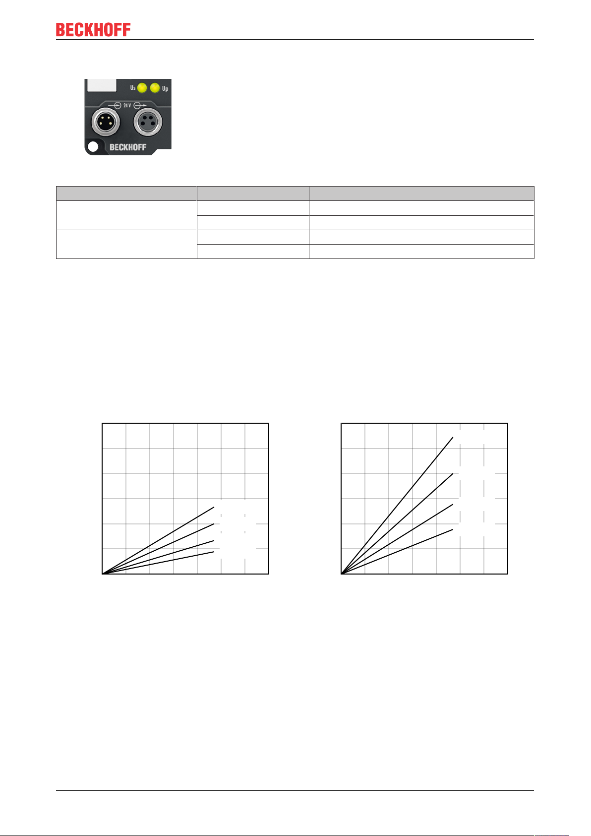
4.2.2 Status LEDs
Fig.7: Status LEDs for the supply voltages
LED Display Meaning
US (control voltage) off Supply voltage US is not present
green illuminated Supply voltage US is present
UP (peripheral voltage) off Supply voltage UP is not present
green illuminated Supply voltage UP is present
4.2.3 Conductor losses
Take into account the voltage drop on the supply line when planning a system. Avoid the voltage drop being
so high that the supply voltage at the box lies below the minimum nominal voltage.
Variations in the voltage of the power supply unit must also be taken into account.
Voltage drop on the supply line
EP3752-0000 17Version: 1.2
Page 18
Mounting and cabling
3 1
24
4.3 EtherCAT
4.3.1 Connectors
NOTE
Risk of confusion: supply voltages and EtherCAT
Defect possible through incorrect insertion.
• Observe the color coding of the connectors:
black: Supply voltages
green: EtherCAT
EtherCAT Box Modules have two green M8 sockets for the incoming and downstream EtherCAT
connections.
Fig.8: EtherCAT connectors
Connection
Fig.9: M8 socket
EtherCAT M8
Signal Contact ZB9010, ZB9020, ZB9030, ZB9032,
Tx + 1 yellow
Tx - 4 orange
Rx + 2 white
Rx - 3 blue
Shield Housing Shield Shield Shield
1)
Core colors according to EN61918
connector
Core colors
ZK1090-6292,
ZK1090-3xxx-xxxx
1)
1)
1)
1)
ZB9031 and old versions of
ZB9030, ZB9032, ZK1090-3xxxxxxx
orange/white white/orange
orange orange
blue/white white/green
blue green
TIA-568B
Adaptation of core colors for cables ZB9030, ZB9032 and ZK1090-3xxxx-xxxx
For standardization, the core colors of the ZB9030, ZB9032 and ZK1090-3xxx-xxxx cables have
been changed to the EN61918 core colors: yellow, orange, white, blue. So there are different color
codes in circulation. The electrical properties of the cables have been retained when the core colors
were changed.
EP3752-000018 Version: 1.2
Page 19

Mounting and cabling
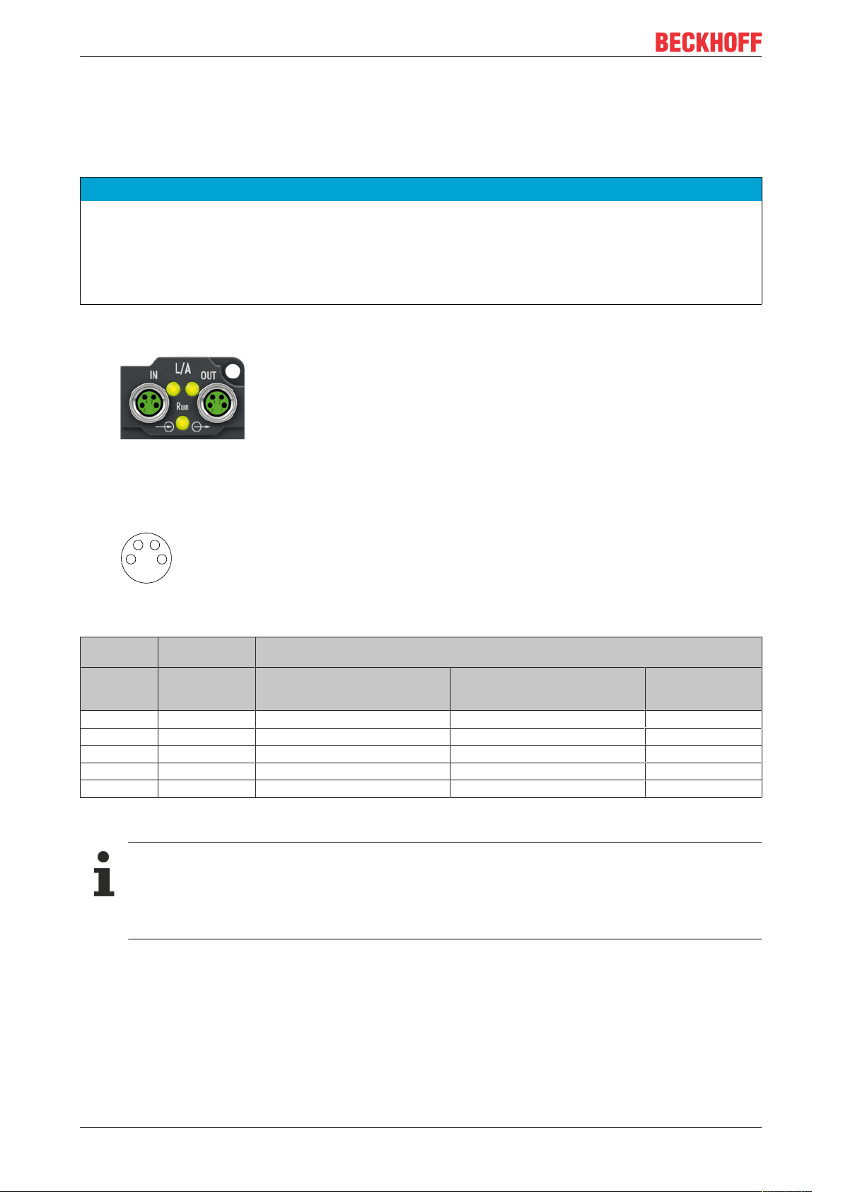
4.3.2 Status LEDs
Fig.10: EtherCAT status LEDs
L/A (Link/Act)
A green LED labelled "L/A" is located next to each EtherCAT socket. The LED indicates the communication
state of the respective socket:
LED Meaning
off no connection to the connected EtherCAT device
lit LINK: connection to the connected EtherCAT device
flashes ACT: communication with the connected EtherCAT device
Run
Each EtherCAT slave has a green LED labelled "Run". The LED signals the status of the slave in the
EtherCAT network:
LED Meaning
off Slave is in "Init" state
flashes uniformly Slave is in "Pre-Operational“ state
flashes sporadically Slave is in "Safe-Operational" state
lit Slave is in "Operational" state
Description of the EtherCAT slave states
4.3.3 Cables
For connecting EtherCAT devices only shielded Ethernet cables that meet the requirements of at least
category5 (CAT5) according to EN50173 or ISO/IEC11801 should be used.
EtherCAT uses four wires for signal transmission.
Thanks to automatic line detection ("Auto MDI-X"), both symmetrical (1:1) or cross-over cables can be used
between Beckhoff EtherCAT.
Detailed recommendations for the cabling of EtherCAT devices
EP3752-0000 19Version: 1.2
Page 20

Mounting and cabling
4.4 UL Requirements
The installation of the EtherCAT Box Modules certified by UL has to meet the following requirements.
Supply voltage
CAUTION
CAUTION!
This UL requirements are valid for all supply voltages of all marked EtherCAT Box Modules!
For the compliance of the UL requirements the EtherCAT Box Modules should only be supplied
• by a 24 VDC supply voltage, supplied by an isolating source and protected by means of a fuse (in accordance with UL248), rated maximum 4 Amp, or
• by a 24 VDC power source, that has to satisfy NEC class 2.
A NEC class 2 power supply shall not be connected in series or parallel with another (class 2) power
source!
CAUTION
CAUTION!
To meet the UL requirements, the EtherCAT Box Modules must not be connected to unlimited power
sources!
Networks
CAUTION
CAUTION!
To meet the UL requirements, EtherCAT Box Modules must not be connected to telecommunication networks!
Ambient temperature range
CAUTION
CAUTION!
To meet the UL requirements, EtherCAT Box Modules has to be operated only at an ambient temperature
range of 0 to 55°C!
Marking for UL
All EtherCAT Box Modules certified by UL (Underwriters Laboratories) are marked with the following label.
Fig.11: UL label
EP3752-000020 Version: 1.2
Page 21

5 Commissioning/Configuration
5.1 Integration in TwinCAT
The procedure for integration in TwinCAT is described in this Quick start guide.
Commissioning/Configuration
EP3752-0000 21Version: 1.2
Page 22
Commissioning/Configuration
AI Inputs Channel 6
AI Inputs Channel 5 AI Inputs Channel 4
AI Inputs Channel 3
AI Inputs Channel 1
AI Inputs Channel 2
Sensor 2
Sensor 1
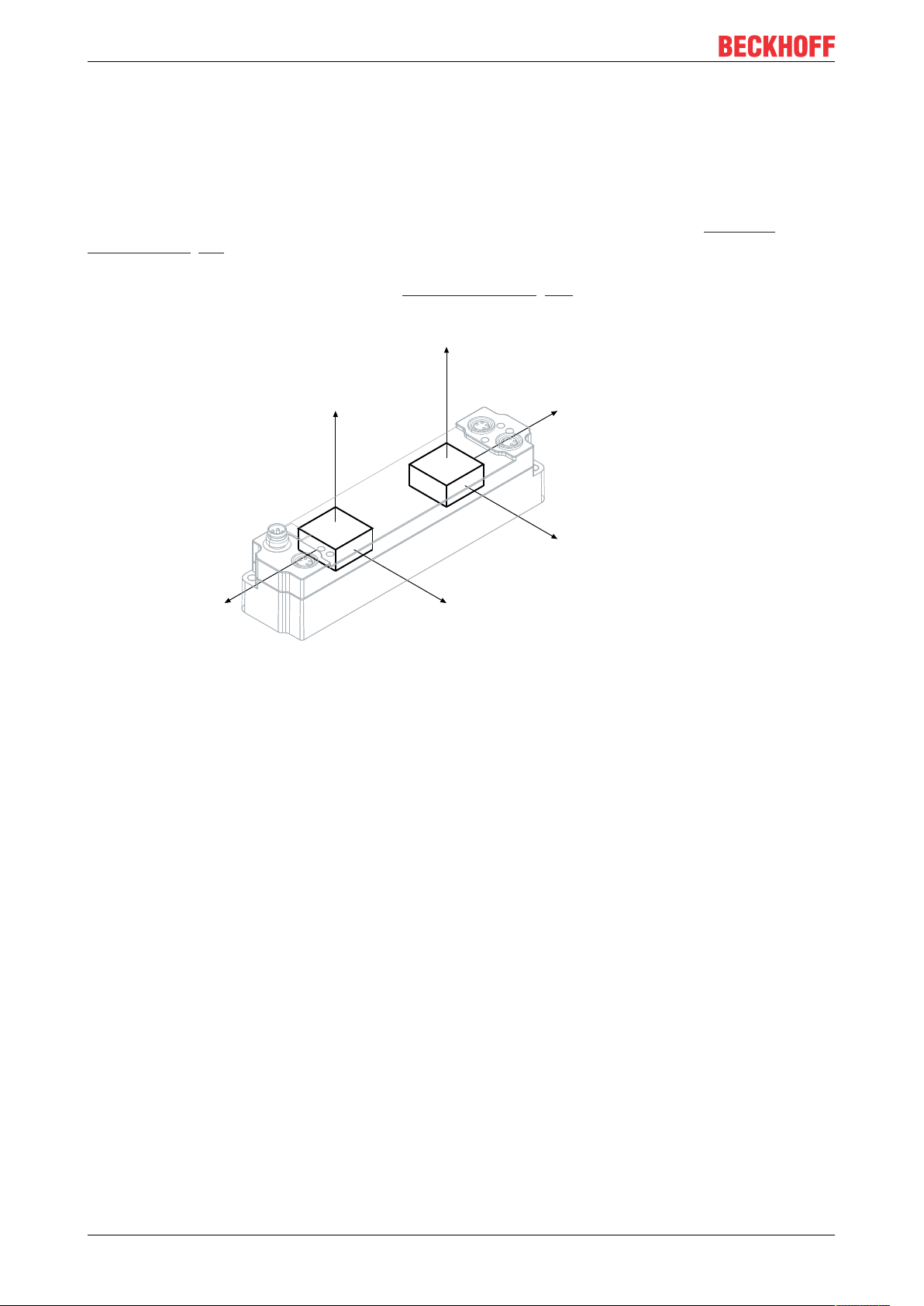
5.2 Acceleration sensors
EP3752-0000 has two accelerometers. Each accelerometer measures the acceleration in all three spatial
directions.
The accelerometers are offset by 90°. This enables a plausibility check of the measured values.
The measured acceleration values can be converted to inclination angles: see chapter on Inclination
measurement [}26].
Assignment of the acceleration axes to the process variables [}13]
Fig.12: Acceleration axes
EP3752-000022 Version: 1.2
Page 23

Commissioning/Configuration
5.2.1 Settings
Scaling of the measured values
The measured values from the accelerometers – X, Y and Z-axis in each case - are output by default scaled
to 1mg/LSB. This representation is preferable, as the measured values are always scaled the same as a
result (irrespective of the other settings in the CoE).
Fig.13: Index 0xF800:1D (default)
The data can also be output as raw values, i.e. just as they are transmitted from the sensors. The relevant
setting needs to be made in index 0xF800:1D in order to do this.
Fig.14: Setting of the representation via index 0xF800:0D "Presentation"
When selecting "Channel setting" in index 0xF800:0D, the representation is set individually for each axis via
the indices 0x80n0:1A.
EP3752-0000 23Version: 1.2
Page 24

Commissioning/Configuration
Measuring range
The measuring range can be selected in index 0xF800:11 "Range".
Fig.15: Setting the measuring range via index 0xF800:11 "Range"
When selecting "Channel setting" in index 0xF800:11, the measuring range is set individually for each
sensor:
• Measuring range for sensor 1: Index 0x8000:19 "Range"
• Measuring range for sensor 2: Index 0x8030:19 "Range"
This setting applies to all axes of the respective sensor. An individual setting for individual axes is not
possible.
Sampling rate and synchronization modes
The sampling rate depends on whether the box's filters are activated. The filters are deactivated by default.
They are described in the chapter Filter [}25].
• The box operates SM-synchronously
if no filters are active. In this mode the EtherCAT cycle time determines the sampling rate: The
measured values are read from the sensors in each EtherCAT cycle.
The sensor operates internally with 10-bit resolution up to a cycle time of 1ms. Below that the
resolution is reduced to 8-bit. The minimum cycle time is 200µs.
• If at least one filter is active,
the box runs in free run with a sampling rate set by CoE index 0xF800:0D "Filter sampling rate".
The resolution is reduced to 8-bit if the sampling rate is increased to 2500Hz or 5000Hz.
EP3752-000024 Version: 1.2
Page 25

Commissioning/Configuration
5.2.2 Filter
Filter mode (FIR and IIR)
EP3752-0000 is equipped with digital filters which, depending on their settings, can adopt the characteristics
of a Finite Impulse Response filter (FIR filter), or of an Infinite Impulse Response filter (IIR-Filter). The filters
are deactivated by default. The activation takes place
• individually for each channel via the indices 0x80n0:06 [}35] from Firmware 02.
• centrally via the 1st channel (index 0x8000:06 [}35]) with Firmware 01.
The filter characteristic is selected individually for each channel via the indices 0x80n0:15 "Filter Settings":
FIR
The mean value of the last 32 measurements is calculated. The internal sampling rate (time interval between
the individual measured values) can be parameterized via index 0xF800:0D "Filter sampling rate".
IIR1…8
The filter with IIR characteristic can be set to one of 8 levels. The higher the level, the higher the attenuation
of the present signal by the filter. The internal sampling rate can be set via index 0xF800:0D "Filter sampling
rate" (unlike other analog boxes in which a fixed cycle time of 1ms is specified).
Setting of the internal sampling rate via index 0xF800:0D
Fig.16: Setting of the internal sampling rate (index 0xF8000:0D)
The internal sampling rate with filters switched on is set via the index 0xF800:0D. On delivery this is set to
1000Hz.
Changing the update rate at 2000Hz and 5000Hz
The resolution is reduced to 8-bit if the rate is increased to 2500Hz or 5000Hz. This is necessary
due to the sensors used.
EP3752-0000 25Version: 1.2
Page 26

Commissioning/Configuration
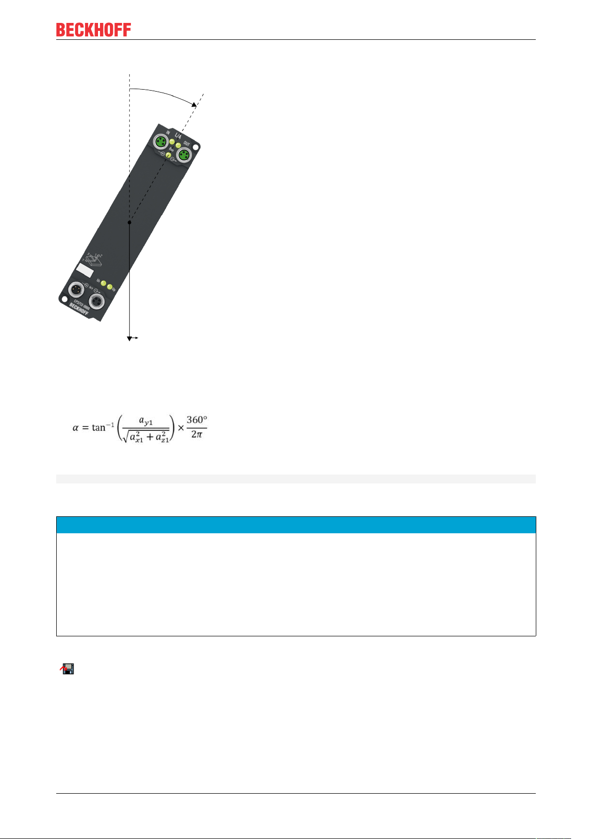
5.2.3 Inclination measurement
The calculation of an angle with higher resolution and accuracy should take place on a PC. The sensors
used are capable of an accuracy of less than 0.1°.
Since the angle values are derived from the acceleration values, which are subject to certain noise, they
have to be filtered via suitable algorithms.
In simple cases this could be a sliding average value, for example.
Fig.17: Angle measurement, process data as acceleration values, calculation on a PC
Fig.18: Signal noise in detail
Color Meaning
Red Angle measured with 1024-step encoder / 4-way analysis for reference
Green Angle trigonometrically calculated on a PC, without noise suppression
blue Fast algorithm
yellow Arithmetic mean (1000 sliding values)
EP3752-000026 Version: 1.2
Page 27
Sample
α
g
Commissioning/Configuration
Equation for calculating the angle α:
Implementation in TwinCAT:
alpha := ATAN(a_y1 / (SQRT(a_x1 * a_x1 + a_z1 * a_z1))) * 360/(2*3.14);
Sample Program
NOTE
Using the sample program
This document contains sample applications of our products for certain areas of application. The application
notices provided here are based on typical features of our products and only serve as samples. The notices
contained in this document explicitly do not refer to specific applications. The customer is therefore responsible for assessing and deciding whether the product is suitable for a particular application. We accept no
responsibility for the completeness and correctness of the source code contained in this document. We reserve the right to modify the content of this document at any time and accept no responsibility for errors and
missing information.
To download the sample program from this documentation please click on the following link:
(https://infosys.beckhoff.com/content/1033/ep3752/Resources/zip/3626380299.zip)
EP3752-0000 27Version: 1.2
Page 28

Commissioning/Configuration
5.3 Restoring the delivery state
To restore the delivery state for backup objects in ELxxxx terminals / EPxxxx- and EPPxxxx boxes, the CoE
object Restore default parameters, SubIndex 001 can be selected in the TwinCAT System Manager (Config
mode).
Fig.19: Selecting the Restore default parameters PDO
Double-click on SubIndex 001 to enter the Set Value dialog. Enter the value 1684107116 in field Dec or the
value 0x64616F6C in field Hex and confirm with OK.
All backup objects are reset to the delivery state.
Fig.20: Entering a restore value in the Set Value dialog
Alternative restore value
In some older terminals / boxes the backup objects can be switched with an alternative restore
value:
Decimal value: 1819238756
Hexadecimal value: 0x6C6F6164
An incorrect entry for the restore value has no effect.
EP3752-000028 Version: 1.2
Page 29

Commissioning/Configuration
5.4 Decommissioning
WARNING
Risk of electric shock!
Bring the bus system into a safe, de-energized state before starting disassembly of the devices!
Disposal
In order to dispose of the device, it must be removed.
In accordance with the WEEE Directive 2012/19/EU, Beckhoff takes back old devices and accessories in
Germany for proper disposal. Transport costs will be borne by the sender.
Return the old devices with the note "for disposal" to:
Beckhoff Automation GmbH & Co. KG
Service Department
Stahlstraße 31
D-33415 Verl
EP3752-0000 29Version: 1.2
Page 30

CoE parameters
6 CoE parameters
6.1 Object overview
EtherCAT XML Device Description
The display matches that of the CoE objects from the EtherCAT XML Device Description. We recommend downloading the latest XML file from the download area of the Beckhoff website and installing it according to installation instructions.
EP3752-000030 Version: 1.2
Page 31

CoE parameters
Index (hex) Name Flags Default value
1000 [}39]
1008 [}39]
1009 [}39]
100A [}39]
1011:0 [}34]
1018:0 [}39]
10F0:0 [}39]
1A00:0 [}40]
1A01:0 [}40]
1A02:0 [}40]
1A03:0 [}40]
1A04:0 [}41]
Subindex Restore default parameters RO 0x01 (1
1011:01 SubIndex 001 RW 0x00000000 (0
Subindex Identity RO 0x04 (4
1018:01 Vendor ID RO 0x00000002 (2
1018:02 Product code RO 0x0EA84052 (245907538
1018:03 Revision RO 0x00100002 (1048578
1018:04 Serial number RO 0x00000000 (0
Subindex Backup parameter handling RO 0x01 (1
10F0:01 Checksum RO 0x00000000 (0
Subindex AI TxPDO-Map Inputs Ch.1 RO 0x06 (6
1A00:01 SubIndex 001 RO 0x0000:00, 6
1A00:02 SubIndex 002 RO 0x6000:07, 1
1A00:03 SubIndex 003 RO 0x0000:00, 7
1A00:04 SubIndex 004 RO 0x6000:0F, 1
1A00:05 SubIndex 005 RO 0x6000:10, 1
1A00:06 SubIndex 006 RO 0x6000:11, 16
Subindex AI TxPDO-Map Inputs Ch.2 RO 0x06 (6
1A01:01 SubIndex 001 RO 0x0000:00, 6
1A01:02 SubIndex 002 RO 0x6010:07, 1
1A01:03 SubIndex 003 RO 0x0000:00, 7
1A01:04 SubIndex 004 RO 0x6010:0F, 1
1A01:05 SubIndex 005 RO 0x6010:10, 1
1A01:06 SubIndex 006 RO 0x6010:11, 16
Subindex AI TxPDO-Map Inputs Ch.3 RO 0x06 (6
1A02:01 SubIndex 001 RO 0x0000:00, 6
1A02:02 SubIndex 002 RO 0x6020:07, 1
1A02:03 SubIndex 003 RO 0x0000:00, 7
1A02:04 SubIndex 004 RO 0x6020:0F, 1
1A02:05 SubIndex 005 RO 0x6020:10, 1
1A02:06 SubIndex 006 RO 0x6020:11, 16
Subindex AI TxPDO-Map Inputs Ch.4 RO 0x06 (6
1A03:01 SubIndex 001 RO 0x0000:00, 6
1A03:02 SubIndex 002 RO 0x6030:07, 1
1A03:03 SubIndex 003 RO 0x0000:00, 7
1A03:04 SubIndex 004 RO 0x6030:0F, 1
1A03:05 SubIndex 005 RO 0x6030:10, 1
1A03:06 SubIndex 006 RO 0x6030:11, 16
Subindex AI TxPDO-Map Inputs Ch.5 RO 0x06 (6
1A04:01 SubIndex 001 RO 0x0000:00, 6
1A04:02 SubIndex 002 RO 0x6040:07, 1
1A04:03 SubIndex 003 RO 0x0000:00, 7
1A04:04 SubIndex 004 RO 0x6040:0F, 1
1A04:05 SubIndex 005 RO 0x6040:10, 1
1A04:06 SubIndex 006 RO 0x6040:11, 16
Device type RO 0x00001389 (5001
Device name RO EP3752-0000
Hardware version RO 00
Software version RO 00
)
dec
)
dec
)
dec
)
dec
)
dec
)
dec
)
dec
)
dec
)
dec
)
dec
)
dec
)
dec
)
dec
)
dec
)
dec
EP3752-0000 31Version: 1.2
Page 32

CoE parameters
Index (hex) Name Flags Default value
1A05:0 [}41]
1C00:0 [}41]
1C12:0 [}41]
1C13:0 [}41]
1C33:0 [}42]
6000:0 [}43]
6010:0 [}43]
6020:0 [}43]
6030:0 [}43]
6040:0 [}43]
Subindex AI TxPDO-Map Inputs Ch.6 RO 0x06 (6
1A05:01 SubIndex 001 RO 0x0000:00, 6
1A05:02 SubIndex 002 RO 0x6050:07, 1
1A05:03 SubIndex 003 RO 0x0000:00, 7
1A05:04 SubIndex 004 RO 0x6050:0F, 1
1A05:05 SubIndex 005 RO 0x6040:10, 1
1A05:06 SubIndex 006 RO 0x6050:11, 16
1A05:02 AI TxPDO-Map Inputs Ch.5 RO 0x06 (6
Subindex Sync manager type RO 0x04 (4
1C00:01 SubIndex 001 RO 0x01 (1
1C00:02 SubIndex 002 RO 0x02 (2
1C00:03 SubIndex 003 RO 0x03 (3
1C00:04 SubIndex 004 RO 0x04 (4
Subindex RxPDO assign RW 0x00 (0
Subindex TxPDO assign RW 0x06 (6
1C13:01 SubIndex 001 RW 0x1A00 (6656
1C13:02 SubIndex 002 RW 0x1A02 (6658
1C13:03 SubIndex 003 RW 0x1A03 (6659
1C13:04 SubIndex 004 RW 0x1A04 (6660
1C13:05 SubIndex 005 RW 0x1A05 (6661
1C13:06 SubIndex 006 RW 0x1A06 (6662
Subindex SM input parameter RO 0x20 (32
1C33:01 Sync mode RW 0x0022 (34
1C33:02 Cycle time RW 0x000F4240 (1000000
1C33:03 Shift time RO 0x00000000 (0
1C33:04 Sync modes supported RO 0x0003 (3
1C33:05 Minimum cycle time RO 0x00030D40 (200000
1C33:06 Calc and copy time RO 0x00000000 (0
1C33:07 Minimum delay time RO 0x00000000 (0
1C33:08 Command RW 0x0000 (0
1C33:09 Maximum Delay time RO 0x00000000 (0
1C33:0B SM event missed counter RO 0x0000 (0
1C33:0C Cycle exceeded counter RO 0x0000 (0
1C33:0D Shift too short counter RO 0x0000 (0
1C33:20 Sync error RO 0x00 (0
Subindex AI Inputs Ch.1 RO 0x11 (17
6000:07 Error RO 0x00 (0
6000:0F TxPDO State RO 0x00 (0
6000:10 TxPDO Toggle RO 0x00 (0
6000:11 Value RO 0x0000 (0
Subindex AI Inputs Ch.2 RO 0x11 (17
6010:07 Error RO 0x00 (0
6010:0F TxPDO State RO 0x00 (0
6010:10 TxPDO Toggle RO 0x00 (0
6010:11 Value RO 0x0000 (0
Subindex AI Inputs Ch.3 RO 0x11 (17
6020:07 Error RO 0x00 (0
6020:0F TxPDO State RO 0x00 (0
6020:10 TxPDO Toggle RO 0x00 (0
6020:11 Value RO 0x0000 (0
Subindex AI Inputs Ch.4 RO 0x11 (17
6030:07 Error RO 0x00 (0
6030:0F TxPDO State RO 0x00 (0
6030:10 TxPDO Toggle RO 0x00 (0
6030:11 Value RO 0x0000 (0
Subindex AI Inputs Ch.5 RO 0x11 (17
6040:07 Error RO 0x00 (0
6040:0F TxPDO State RO 0x00 (0
)
dec
)
dec
)
dec
)
dec
)
dec
)
dec
)
dec
)
dec
)
dec
)
dec
dec
dec
dec
dec
dec
)
dec
)
dec
)
dec
)
dec
)
dec
dec
)
dec
)
dec
)
dec
)
dec
dec
)
dec
)
dec
)
dec
)
dec
dec
)
dec
)
dec
)
dec
)
dec
dec
)
dec
)
dec
)
dec
)
dec
)
dec
)
dec
)
dec
)
dec
)
dec
)
dec
)
dec
)
dec
)
)
dec
)
dec
)
dec
)
)
dec
)
)
)
)
)
)
)
EP3752-000032 Version: 1.2
Page 33

CoE parameters
Index (hex) Name Flags Default value
6050:0 [}43]
8000:0 [}35]
8010:0 [}35]
8020:0 [}36]
8030:0 [}36]
8040:0 [}37]
8050:0 [}37]
8060:0 [}38]
(FW01)
F000:0 [}44]
F008 [}44]
F010:0 [}44]
F800:0 [}38]
(from FW02)
6040:10 TxPDO Toggle RO 0x00 (0
6040:11 Value RO 0x0000 (0
Subindex AI Inputs Ch.6 RO 0x11 (17
6050:07 Error RO 0x00 (0
6050:0F TxPDO State RO 0x00 (0
6050:10 TxPDO Toggle RO 0x00 (0
6050:11 Value RO 0x0000 (0
Subindex AI Settings Ch.1 RW 0x1A (26
8000:06 Enable filter RW 0x00 (0
8000:15 Filter settings RW 0x0002 (2
8000:19 Range RW 0x0000 (0
8000:1A Presentation RW 0x0001 (1
Subindex AI Settings Ch.2 RW 0x1A (26
8010:06 Enable filter RW 0x00 (0
8010:15 Filter settings RW 0x0002 (2
8010:19 Range RW 0x0000 (0
8010:1A Presentation RW 0x0001 (1
Subindex AI Settings Ch.3 RW 0x1A (26
8020:06 Enable filter RW 0x00 (0
8020:15 Filter settings RW 0x0002 (2
8020:19 Range RW 0x0000 (0
8020:1A Presentation RW 0x0001 (1
Subindex AI Settings Ch.4 RW 0x1A (26
8030:06 Enable filter RW 0x00 (0
8030:15 Filter settings RW 0x0002 (2
8030:19 Range RW 0x0000 (0
8030:1A Presentation RW 0x0001 (1
Subindex AI Settings Ch.5 RW 0x1A (26
8040:06 Enable filter RW 0x00 (0
8040:15 Filter settings RW 0x0002 (2
8040:19 Range RW 0x0000 (0
8040:1A Presentation RW 0x0001 (1
Subindex AI Settings Ch.6 RW 0x1A (26
8050:06 Enable filter RW 0x00 (0
8050:15 Filter settings RW 0x0002 (2
8050:19 Range RW 0x0000 (0
8050:1A Presentation RW 0x0001 (1
Subindex SAI Settings RW 0x1D (29
8060:0D Filter sampling rate RW 0x0002 (2
8060:11 Range RW 0x0000 (0
8060:1D Presentation RW 0x0001 (1
Subindex Modular device profile RO 0x02 (2
F000:01 Module index distance RO 0x0010 (16
F000:02 Maximum number of modules RO 0x0002 (2
Code word RW 0x00000000 (0
Subindex Module list RW 0x02 (2
F010:01 SubIndex 001 RW 0x00000258 (600
F010:02 SubIndex 002 RW 0x00000258 (600
Subindex SAI Settings RW 0x1D (29
F800:0D Filter sampling rate RW 0x0002 (2
F800:11 Range RW 0x0000 (0
F800:1D Presentation RW 0x0001 (1
)
dec
dec
)
dec
)
dec
)
dec
)
dec
dec
)
dec
)
dec
dez
dez
dez
)
dec
)
dec
dez
dez
dez
)
dec
)
dec
dez
dez
dez
)
dec
)
dec
dez
dez
dez
)
dec
)
dec
dez
dez
dez
)
dec
)
dec
dez
dez
dez
)
dec
dez
dez
dez
)
dec
dec
dec
)
dec
)
dec
dec
dec
dec
)
)
)
)
)
)
)
)
)
)
)
)
)
)
)
)
)
)
)
)
)
)
)
)
)
)
dec
)
dec
)
dec
)
)
)
Key
Flags:
RO (Read Only): This object can only be read.
RW (Read/Write): This object can be read and written to.
EP3752-0000 33Version: 1.2
Page 34

CoE parameters
6.2 Object description and parameterization
EtherCAT XML Device Description
The display matches that of the CoE objects from the EtherCAT XML Device Description. We recommend downloading the latest XML file from the download area of the Beckhoff website and installing it according to installation instructions.
Parameterization via the CoE list (CAN over EtherCAT)
The EtherCAT device is parameterized via the CoE - Online tab (double-click on the respective object) or via the Process Data tab (allocation of PDOs).
Introduction
The CoE overview contains objects for different intended applications:
• Objects required for parameterization [}34] during commissioning
• Objects for indicating internal settings [}39] (may be fixed)
• Further profile-specific objects [}43] indicating inputs, outputs and status information
The following section first describes the objects required for normal operation, followed by a complete
overview of missing objects.
Objects to be parameterized during commissioning
Index 1011 Restore default parameters
Index (hex) Name Meaning Data type Flags Default
1011:0 Restore default pa-
rameters
1011:01 SubIndex 001 If this object is set to "0x64616F6C" in the Set Value
Restore default settings UINT8 RO 0x01 (1
UINT32 RW 0x00000000 (0
Dialog, all backup objects are reset to their delivery
state.
)
dec
)
dec
EP3752-000034 Version: 1.2
Page 35

CoE parameters
Index 8000 AI Settings Ch.1
Index (hex) Name Meaning Data type Flags Default
8000:0 AI Settings Ch.1 UINT8 RO 0x1A (26
8000:06 Enable filter Activates the filter. BOOLEAN RW 0x00 (0
8000:15 Filter settings This object determines the filter settings of all chan-
nels of the module when it is activated via Enable fil-
ter index 0x80n0:06.
0 FIR
2 IIR1
3 IIR2
4 IIR3
5 IIR4
6 IIR5
7 IIR6
8 IIR7
9 IIR8
8000:19 Range Setting the measuring range:
• 0
: +-2G
dec
• 1
: +-4G
dec
• 2
: +-8G
dec
• 3
: +-16G
dec
8000:1A Presentation Representation of the data
• 0
: Raw values
dec
• 1
: milli G (mG)
dec
UINT16 RW 0x0002 (2
UINT16 RW 0x0000 (0
UINT16 RW 0x0001 (1
)
dec
)
dec
)
dec
)
dec
)
dec
Index 8010 AI Settings Ch.2
Index (hex) Name Meaning Data type Flags Default
8010:0 AI Settings Ch.2 UINT8 RO 0x1A (26
8010:06 Enable filter Activates the filter. BOOLEAN RW 0x00 (0
8010:15 Filter settings This object determines the filter settings of all chan-
nels of the module when it is activated via Enable fil-
ter index 0x80n0:06.
0 FIR
2 IIR1
3 IIR2
4 IIR3
5 IIR4
6 IIR5
7 IIR6
8 IIR7
9 IIR8
8010:19 Range Setting the measuring range:
• 0
: +-2G
dec
• 1
: +-4G
dec
• 2
: +-8G
dec
• 3
: +-16G
dec
8010:1A Presentation Representation of the data
• 0
: Raw values
dec
• 1
: milli G (mG)
dec
UINT16 RW 0x0002 (2
UINT16 RW 0x0000 (0
UINT16 RW 0x0001 (1
)
dec
)
dec
)
dec
)
dec
)
dec
EP3752-0000 35Version: 1.2
Page 36

CoE parameters
Index 8020 AI Settings Ch.3
Index (hex) Name Meaning Data type Flags Default
8020:0 AI Settings Ch.3 UINT8 RO 0x1A (26
8020:06 Enable filter Activates the filter. BOOLEAN RW 0x00 (0
8020:15 Filter settings This object determines the filter settings of all chan-
nels of the module when it is activated via Enable fil-
ter index 0x80n0:06.
0 FIR
2 IIR1
3 IIR2
4 IIR3
5 IIR4
6 IIR5
7 IIR6
8 IIR7
9 IIR8
8020:19 Range Setting the measuring range:
• 0
: +-2G
dec
• 1
: +-4G
dec
• 2
: +-8G
dec
• 3
: +-16G
dec
8020:1A Presentation Representation of the data
• 0
: Raw values
dec
• 1
: milli G (mG)
dec
UINT16 RW 0x0002 (2
UINT16 RW 0x0000 (0
UINT16 RW 0x0001 (1
)
dec
)
dec
)
dec
)
dec
)
dec
Index 8030 AI Settings Ch.4
Index (hex) Name Meaning Data type Flags Default
8030:0 AI Settings Ch.4 UINT8 RO 0x11 (21
8030:06 Enable filter Activates the filter. BOOLEAN RW 0x00 (0
8030:15 Filter settings This object determines the filter settings of all chan-
nels of the module when it is activated via Enable fil-
ter index 0x80n0:06.
0 FIR
2 IIR1
3 IIR2
4 IIR3
5 IIR4
6 IIR5
7 IIR6
8 IIR7
9 IIR8
8030:19 Range Setting the measuring range:
• 0
: +-2G
dec
• 1
: +-4G
dec
• 2
: +-8G
dec
• 3
: +-16G
dec
8030:1A Presentation Representation of the data
• 0
: Raw values
dec
• 1
: milli G (mG)
dec
UINT16 RW 0x0002 (2
UINT16 RW 0x0000 (0
UINT16 RW 0x0001 (1
)
dec
)
dec
)
dec
)
dec
)
dec
EP3752-000036 Version: 1.2
Page 37

CoE parameters
Index 8040 AI Settings Ch.5
Index (hex) Name Meaning Data type Flags Default
8040:0 AI Settings Ch.5 UINT8 RO 0x1A (26
8040:06 Enable filter Activates the filter. BOOLEAN RW 0x00 (0
8040:15 Filter settings This object determines the filter settings of all chan-
nels of the module when it is activated via Enable fil-
ter index 0x80n0:06.
0 FIR
2 IIR1
3 IIR2
4 IIR3
5 IIR4
6 IIR5
7 IIR6
8 IIR7
9 IIR8
8040:19 Range Setting the measuring range:
• 0
: +-2G
dec
• 1
: +-4G
dec
• 2
: +-8G
dec
• 3
: +-16G
dec
8040:1A Presentation Representation of the data
• 0
: Raw values
dec
• 1
: milli G (mG)
dec
UINT16 RW 0x0002 (2
UINT16 RW 0x0000 (0
UINT16 RW 0x0001 (1
)
dec
)
dec
)
dec
)
dec
)
dec
Index 8050 AI Settings Ch.6
Index (hex) Name Meaning Data type Flags Default
8050:0 AI Settings Ch.6 UINT8 RO 0x1A (26
8050:06 Enable filter Activates the filter. BOOLEAN RW 0x00 (0
8050:15 Filter settings This object determines the filter settings of all chan-
nels of the module when it is activated via Enable fil-
ter index 0x80n0:06.
0 FIR
2 IIR1
3 IIR2
4 IIR3
5 IIR4
6 IIR5
7 IIR6
8 IIR7
9 IIR8
8050:19 Range Setting the measuring range:
• 0
: +-2G
dec
• 1
: +-4G
dec
• 2
: +-8G
dec
• 3
: +-16G
dec
8050:1A Presentation Representation of the data
• 0
: Raw values
dec
• 1
: milli G (mG)
dec
UINT16 RW 0x0002 (2
UINT16 RW 0x0000 (0
UINT16 RW 0x0001 (1
)
dec
)
dec
)
dec
)
dec
)
dec
EP3752-0000 37Version: 1.2
Page 38

CoE parameters
Index 8060 SAI Settings (Firmware 01)
The object with index 8060 is invisible in the object directory from Firmware 02. However, it can still be read
and written via SDO access. This ensures backward compatibility with PLC programs that were written prior
to the release of Firmware 02.
The content of index 8060 is mirrored in index F800 [}38] from Firmware 02.
Index (hex) Name Meaning Data type Flags Default
8060:0 SAI Settings UINT8 RO 0x1D (29
8060:0D Filter sampling rate Selection of the internal sampling rate:
• 0
: 200Hz
dec
• 1
: 500Hz
dec
• 2
: 1000Hz
dec
• 3
: 2500Hz
dec
• 4
: 5000Hz
dec
UINT16 RW 0x0002 (2
• The sensor resolution is reduced to 8-bit if the
rate is increased to 2500Hz or 5000Hz.
8060:11 Range Setting the measuring range:
• 0
: +-2G
dec
• 1
: +-4G
dec
• 2
: +-8G
dec
• 3
: +-16G
dec
8060:1D Presentation Representation of the data
• 0
: Raw values
dec
• 1
: milli G (mG)
dec
UINT16 RW 0x0000 (0
UINT16 RW 0x0001 (1
)
dec
)
dec
)
dec
)
dec
Index F800 SAI Settings (from Firmware 02)
Index (hex) Name Meaning Data type Flags Default
F800:0 SAI Settings UINT8 RO 0x1D (29
F800:0D Filter sampling rate Selection of the internal sampling rate:
• 0
: 200Hz
dec
• 1
: 500Hz
dec
• 2
: 1000Hz
dec
• 3
: 2500Hz
dec
• 4
: 5000Hz
dec
• The sensor resolution is reduced to 8-bit if the
rate is increased to 2500Hz or 5000Hz.
F800:11 Range Setting the measuring range:
• 0
: +-2G
dec
• 1
: +-4G
dec
• 2
: +-8G
dec
• 3
: +-16G
dec
• 255
: Channel setting: The measuring range
dec
is set individually for each channel via the
indices 0x80n0:19.
F800:1D Presentation Representation of the data
• 0
: Raw values
dec
• 1
: milli G (mG)
dec
• 255
: Channel setting: The representation is
dec
set channel-wise via the indices 0x80n0:1A.
UINT16 RW 0x0002 (2
UINT16 RW 0x0000 (0
UINT16 RW 0x0001 (1
)
dec
)
dec
)
dec
)
dec
EP3752-000038 Version: 1.2
Page 39

CoE parameters
Additional objects
Standard objects (0x1000-0x1FFF)
The standard objects have the same meaning for all EtherCAT slaves.
Index 1000 Device type
Index (hex) Name Meaning Data type Flags Default
1000:0 Device type Device type of the EtherCAT slave: The Lo-Word con-
tains the CoE profile used (5001). The Hi-Word contains the module profile according to the modular de-
UINT32 RO 0x00001389
(5001
)
dec
vice profile.
Index 1008 Device name
Index (hex) Name Meaning Data type Flags Default
1008:0 Device name Device name of the EtherCAT slave STRING RO EP3752-0000
Index 1009 Hardware version
Index (hex) Name Meaning Data type Flags Default
1009:0 Hardware version Hardware version of the EtherCAT slave STRING RO 00
Index 100A Software Version
Index (hex) Name Meaning Data type Flags Default
100A:0 Software version Firmware version of the EtherCAT slave STRING RO 00
Index 1018 Identity
Index (hex) Name Meaning Data type Flags Default
1018:0 Identity Information for identifying the slave UINT8 RO 0x04 (4
)
dec
1018:01 Vendor ID Vendor ID of the EtherCAT slave UINT32 RO 0x00000002 (2
1018:02 Product code Product code of the EtherCAT slave UINT32 RO 0x0EA84052
(245907538
1018:03 Revision Revision numberof the EtherCAT slave; the Low Word
(bit 0-15) indicates the special terminal number, the
High Word (bit 16-31) refers to the device description
1018:04 Serial number Serial number of the EtherCAT slave; the Low Byte (bit
UINT32 RO 0x00100002
(1048578
)
dec
UINT32 RO 0x00000000 (0
0-7) of the Low Word contains the year of production,
the High Byte (bit 8-15) of the Low Word contains the
week of production, the High Word (bit 16-31) is 0
Index 10F0 Backup parameter handling
Index (hex) Name Meaning Data type Flags Default
10F0:0 Backup parameter
handling
10F0:01 Checksum Checksum across all backup entries of the EtherCAT
Information for standardized loading and saving of
backup entries
slave
UINT8 RO 0x01 (1
)
dec
UINT32 RO 0x00000000 (0
)
dec
)
dec
)
dec
)
dec
EP3752-0000 39Version: 1.2
Page 40

CoE parameters
Index 1A00 AI TxPDO-Map Inputs Ch.1
Index (hex) Name Meaning Data type Flags Default
1A00:0 AI TxPDO-Map In-
puts Ch.1
PDO Mapping TxPDO 1 UINT8 RO 0x06 (6
)
dec
1A00:01 SubIndex 001 1. PDO Mapping entry (6 bit align) UINT32 RO 0x0000:00, 6
1A00:02 SubIndex 002 2. PDO Mapping entry (object 0x6000 (AI Inputs Ch.1),
UINT32 RO 0x6000:07, 1
entry 0x07 (Error))
1A00:03 SubIndex 003 3. PDO Mapping entry (7 bit align) UINT32 RO 0x0000:00, 7
1A00:04 SubIndex 004 4. PDO Mapping entry (object 0x6000 (AI Inputs Ch.1),
UINT32 RO 0x6000:0F, 1
entry 0x0F (TxPDO State))
1A00:05 SubIndex 005 5. PDO Mapping entry (object 0x6000 (AI Inputs Ch.1),
UINT32 RO 0x6000:10, 1
entry 0x10 (TxPDO Toggle))
1A00:06 SubIndex 006 6. PDO Mapping entry (object 0x6000 (AI Inputs Ch.1),
UINT32 RO 0x6000:11, 16
entry 0x11 (Value))
Index 1A01 AI TxPDO-Map Inputs Ch.2
Index (hex) Name Meaning Data type Flags Default
1A01:0 AI TxPDO-Map In-
puts Ch.1
1A01:01 SubIndex 001 1. PDO Mapping entry (6 bit align) UINT32 RO 0x0000:00, 6
1A01:02 SubIndex 002 2. PDO Mapping entry (object 0x6010 (AI Inputs Ch.2),
1A01:03 SubIndex 003 3. PDO Mapping entry (7 bit align) UINT32 RO 0x0010:00, 7
1A01:04 SubIndex 004 4. PDO Mapping entry (object 0x6010 (AI Inputs Ch.2),
1A01:05 SubIndex 005 5. PDO Mapping entry (object 0x6010 (AI Inputs Ch.2),
1A01:06 SubIndex 006 6. PDO Mapping entry (object 0x6010 (AI Inputs Ch.2),
PDO Mapping TxPDO 2 UINT8 RO 0x06 (6
UINT32 RO 0x6010:07, 1
entry 0x07 (Error))
UINT32 RO 0x6010:0F, 1
entry 0x0F (TxPDO State))
UINT32 RO 0x6010:10, 1
entry 0x10 (TxPDO Toggle))
UINT32 RO 0x6010:11, 16
entry 0x11 (Value))
)
dec
Index 1A02 AI TxPDO-Map Inputs Ch.3
Index (hex) Name Meaning Data type Flags Default
1A02:0 AI TxPDO-Map In-
puts Ch.3
PDO Mapping TxPDO 3 UINT8 RO 0x06 (6
)
dec
1A02:01 SubIndex 001 1. PDO Mapping entry (6 bit align) UINT32 RO 0x0000:00, 6
1A02:02 SubIndex 002 2. PDO Mapping entry (object 0x6020 (AI Inputs Ch.3),
UINT32 RO 0x6020:07, 1
entry 0x07 (Error))
1A02:03 SubIndex 003 3. PDO Mapping entry (7 bit align) UINT32 RO 0x0000:00, 7
1A02:04 SubIndex 004 4. PDO Mapping entry (object 0x6020 (AI Inputs Ch.3),
UINT32 RO 0x6020:0F, 1
entry 0x0F (TxPDO State))
1A02:05 SubIndex 005 5. PDO Mapping entry (object 0x6020 (AI Inputs Ch.3),
UINT32 RO 0x6020:10, 1
entry 0x10 (TxPDO Toggle))
1A02:06 SubIndex 006 6. PDO Mapping entry (object 0x6020 (AI Inputs Ch.3),
UINT32 RO 0x6020:11, 16
entry 0x11 (Value))
Index 1A03 AI TxPDO-Map Inputs Ch.4
Index (hex) Name Meaning Data type Flags Default
1A03:0 AI TxPDO-Map In-
puts Ch.4
1A03:01 SubIndex 001 1. PDO Mapping entry (6 bit align) UINT32 RO 0x0000:00, 6
1A03:02 SubIndex 002 2. PDO Mapping entry (object 0x6030 (AI Inputs Ch.4),
1A03:03 SubIndex 003 3. PDO Mapping entry (7 bit align) UINT32 RO 0x0000:00, 7
1A03:04 SubIndex 004 4. PDO Mapping entry (object 0x6030 (AI Inputs Ch.4),
1A03:05 SubIndex 005 5. PDO Mapping entry (object 0x6030 (AI Inputs Ch.4),
1A03:06 SubIndex 006 6. PDO Mapping entry (object 0x6030 (AI Inputs Ch.4),
PDO Mapping TxPDO 4 UINT8 RO 0x06 (6
UINT32 RO 0x6030:07, 1
entry 0x07 (Error))
UINT32 RO 0x6030:0F, 1
entry 0x0F (TxPDO State))
UINT32 RO 0x6030:10, 1
entry 0x10 (TxPDO Toggle))
UINT32 RO 0x6030:11, 16
entry 0x11 (Value))
)
dec
EP3752-000040 Version: 1.2
Page 41

CoE parameters
Index 1A04 AI TxPDO-Map Inputs Ch.5
Index (hex) Name Meaning Data type Flags Default
1A04:0 AI TxPDO-Map In-
puts Ch.5
PDO Mapping TxPDO 5 UINT8 RO 0x06 (6
)
dec
1A04:01 SubIndex 001 1. PDO Mapping entry (6 bit align) UINT32 RO 0x0000:00, 6
1A04:02 SubIndex 002 2. PDO Mapping entry (object 0x6040 (AI Inputs Ch.5),
UINT32 RO 0x6040:07, 1
entry 0x07 (Error))
1A04:03 SubIndex 003 3. PDO Mapping entry (7 bit align) UINT32 RO 0x0000:00, 7
1A04:04 SubIndex 004 4. PDO Mapping entry (object 0x6040 (AI Inputs Ch.5),
UINT32 RO 0x6040:0F, 1
entry 0x0F (TxPDO State))
1A04:05 SubIndex 005 5. PDO Mapping entry (object 0x6040 (AI Inputs Ch.5),
UINT32 RO 0x6040:10, 1
entry 0x10 (TxPDO Toggle))
1A04:06 SubIndex 006 6. PDO Mapping entry (object 0x6040 (AI Inputs Ch.5),
UINT32 RO 0x6040:11, 16
entry 0x11 (Value))
Index 1A05 AI TxPDO-Map Inputs Ch.6
Index (hex) Name Meaning Data type Flags Default
1A05:0 AI TxPDO-Map In-
puts Ch.6
1A05:01 SubIndex 001 1. PDO Mapping entry (6 bit align) UINT32 RO 0x0000:00, 6
1A05:02 SubIndex 002 2. PDO Mapping entry (object 0x6050 (AI Inputs Ch.6),
1A05:03 SubIndex 003 3. PDO Mapping entry (7 bit align) UINT32 RO 0x0000:00, 7
1A05:04 SubIndex 004 4. PDO Mapping entry (object 0x6050 (AI Inputs Ch.6),
1A05:05 SubIndex 005 5. PDO Mapping entry (object 0x6050 (AI Inputs Ch.6),
1A05:06 SubIndex 006 6. PDO Mapping entry (object 0x6050 (AI Inputs Ch.6),
PDO Mapping TxPDO 5 UINT8 RO 0x06 (6
UINT32 RO 0x6050:07, 1
entry 0x07 (Error))
UINT32 RO 0x6050:0F, 1
entry 0x0F (TxPDO State))
UINT32 RO 0x6050:10, 1
entry 0x10 (TxPDO Toggle))
UINT32 RO 0x6050:11, 16
entry 0x11 (Value))
)
dec
Index 1C00 Sync manager type
Index (hex) Name Meaning Data type Flags Default
1C00:0 Sync manager type Using the Sync Managers UINT8 RO 0x04 (4
1C00:01 SubIndex 001 Sync-Manager Type Channel 1: Mailbox Write UINT8 RO 0x01 (1
1C00:02 SubIndex 002 Sync-Manager Type Channel 2: Mailbox Read UINT8 RO 0x02 (2
1C00:03 SubIndex 003 Sync-Manager Type Channel 3: Process Data Write
UINT8 RO 0x03 (3
(Outputs)
1C00:04 SubIndex 004 Sync-Manager Type Channel 4: Process Data Read (In-
UINT8 RO 0x04 (4
puts)
Index 1C12 RxPDO assign
Index (hex) Name Meaning Data type Flags Default
1C12:0 RxPDO assign PDO Assign Outputs UINT8 RW 0x00 (0
Index 1C13 TxPDO assign
Index (hex) Name Meaning Data type Flags Default
1C13:0 TxPDO assign PDO Assign Inputs UINT8 RW 0x04 (4
1C13:01 Subindex 001 1. allocated TxPDO (contains the index of the associ-
ated TxPDO mapping object)
1C13:02 Subindex 002 2. allocated TxPDO (contains the index of the associ-
ated TxPDO mapping object)
1C13:03 Subindex 003 3. allocated TxPDO (contains the index of the associ-
ated TxPDO mapping object)
1C13:04 Subindex 004 4. allocated TxPDO (contains the index of the associ-
ated TxPDO mapping object)
1C13:05 Subindex 005 5. allocated TxPDO (contains the index of the associ-
ated TxPDO mapping object)
1C13:06 Subindex 006 6. allocated TxPDO (contains the index of the associ-
ated TxPDO mapping object)
UINT16 RW 0x1A00 (6656
UINT16 RW 0x1A01 (6657
UINT16 RW 0x1A02 (6658
UINT16 RW 0x1A03 (6659
UINT16 RW 0x1A04 (6660
UINT16 RW 0x1A06 (6662
)
dec
)
dec
)
dec
)
dec
)
dec
)
dec
)
dec
)
dec
)
dec
)
dec
)
dec
)
dec
)
dec
EP3752-0000 41Version: 1.2
Page 42

CoE parameters
Index 1C33 SM input parameter
Index (hex) Name Meaning Data type Flags Default
1C33:0 SM input parameter Synchronization parameters for the inputs UINT8 RO 0x20 (32
1C33:01 Sync mode Current synchronization mode:
UINT16 RW 0x0022 (34
• 0: Free Run
• 1: Synchron with SM 3 Event (no outputs
available)
• 2: DC - Synchron with SYNC0 Event
• 3: DC - Synchron with SYNC1 Event
• 34: Synchron with SM 2 Event (outputs
available)
1C33:02 Cycle time Cycle time (in ns):
• Free Run: Cycle time of the local timer
UINT32 RW 0x000F4240
(1000000
• Synchron with SM 2 Event: Master cycle time
• DC mode: SYNC0/SYNC1 Cycle Time
1C33:03 Shift time Time between SYNC0 event and reading of the inputs
UINT32 RO 0x00000000 (0
(in ns, only DC mode)
1C33:04 Sync modes sup-
ported
Supported synchronization modes:
• Bit 0: free run is supported
UINT16 RO 0x0003 (3
• Bit 1: Synchron with SM 2 Event is supported
(outputs available)
• Bit 1: Synchron with SM 3 Event is supported (no
outputs available)
• Bit 2-3 = 01: DC mode is supported
• Bit 4-5 = 01: Input Shift through local event
(outputs available)
• Bit 4-5 = 10: Input Shift with SYNC1 event (no
outputs available)
• Bit 14 = 1: dynamic times (measurement through
writing of 0x1C32:08 or 0x1C33:08)
1C33:05 Minimum cycle time Minimum cycle time supported (in ns) UINT32 RO 0x0003D040
(20000
1C33:06 Calc and copy time Time between reading of the inputs and availability of
UINT32 RO 0x00000000 (0
the inputs for the master (in ns, only DC mode)
1C33:07 Minimum delay time UINT32 RO 0x00000000 (0
1C33:08 Command With this entry the real required process data provision
UINT16 RW 0x0000 (0
time can be measured.
0: Measurement of the local cycle time is stopped
1: Measurement of the local cycle time is started
The entries 0x1C33:03, 0x1C33:06, 0x1C33:09 are updated with the maximum measured values.
For a subsequent measurement the measured values
are reset
1C33:09 Maximum Delay
time
1C33:0B SM event missed
counter
1C33:0C Cycle exceeded
counter
Time between SYNC1 event and reading of the inputs
(in ns, only DC mode)
Number of missed SM events in OPERATIONAL (DC
mode only)
Number of occasions the cycle time was exceeded in
OPERATIONAL (cycle was not completed in time or the
UINT32 RO 0x00000000 (0
UINT16 RO 0x0000 (0
UINT16 RO 0x0000 (0
next cycle began too early)
1C33:0D Shift too short
counter
1C33:20 Sync error The synchronization was not correct in the last cycle
Number of occasions that the interval between SYNC0
and SYNC1 event was too short (DC mode only)
UINT16 RO 0x0000 (0
BOOLEAN RO 0x00 (0
(outputs were output too late; DC mode only)
)
dec
dec
)
dec
dec
)
dec
dec
dec
dec
dec
)
dec
)
)
dec
)
)
dec
)
dec
)
)
dec
)
)
)
EP3752-000042 Version: 1.2
Page 43

CoE parameters
Profile-specific objects (0x6000-0xFFFF)
The profile-specific objects have the same meaning for all EtherCAT slaves that support the profile 5001.
Index 6000 AI Inputs Ch.1
Index (hex) Name Meaning Data type Flags Default
6000:0 AI Inputs Ch.1 UINT8 RO 0x11 (17
6000:07 Error BOOLEAN RO 0x00 (0
6000:0F TxPDO State BOOLEAN RO 0x00 (0
6000:10 TxPDO Toggle BOOLEAN RO 0x00 (0
6000:11 Value INT16 RO 0x0000 (0
)
dec
)
dec
)
dec
)
dec
dec
Index 6010 AI Inputs Ch.2
Index (hex) Name Meaning Data type Flags Default
6010:0 AI Inputs Ch.2 UINT8 RO 0x11 (17
6010:07 Error BOOLEAN RO 0x00 (0
6010:0F TxPDO State BOOLEAN RO 0x00 (0
6010:10 TxPDO Toggle BOOLEAN RO 0x00 (0
6010:11 Value INT16 RO 0x0000 (0
)
dec
)
dec
)
dec
)
dec
dec
)
)
Index 6020 AI Inputs Ch.3
Index (hex) Name Meaning Data type Flags Default
6020:0 AI Inputs Ch.3 UINT8 RO 0x11 (17
6020:07 Error BOOLEAN RO 0x00 (0
6020:0F TxPDO State BOOLEAN RO 0x00 (0
6020:10 TxPDO Toggle BOOLEAN RO 0x00 (0
6020:11 Value INT16 RO 0x0000 (0
Index 6030 AI Inputs Ch.4
Index (hex) Name Meaning Data type Flags Default
6030:0 AI Inputs Ch.4 UINT8 RO 0x11 (17
6030:07 Error BOOLEAN RO 0x00 (0
6030:0F TxPDO State BOOLEAN RO 0x00 (0
6030:10 TxPDO Toggle BOOLEAN RO 0x00 (0
6030:11 Value INT16 RO 0x0000 (0
Index 6040 AI Inputs Ch.5
Index (hex) Name Meaning Data type Flags Default
6040:0 AI Inputs Ch.5 UINT8 RO 0x11 (17
6040:07 Error BOOLEAN RO 0x00 (0
6040:0F TxPDO State BOOLEAN RO 0x00 (0
6040:10 TxPDO Toggle BOOLEAN RO 0x00 (0
6040:11 Value INT16 RO 0x0000 (0
)
dec
)
dec
)
dec
)
dec
)
dec
)
dec
)
dec
)
dec
)
dec
)
dec
)
dec
)
dec
)
dec
)
dec
)
dec
Index 6050 AI Inputs Ch.6
Index (hex) Name Meaning Data type Flags Default
6050:0 AI Inputs Ch.6 UINT8 RO 0x11 (17
6050:07 Error BOOLEAN RO 0x00 (0
6050:0F TxPDO State BOOLEAN RO 0x00 (0
6050:10 TxPDO Toggle BOOLEAN RO 0x00 (0
6050:11 Value INT16 RO 0x0000 (0
EP3752-0000 43Version: 1.2
)
dec
)
dec
)
dec
)
dec
)
dec
Page 44

CoE parameters
Index F000 Modular device profile
Index (hex) Name Meaning Data type Flags Default
F000:0 Modular device pro-
file
F000:01 Module index dis-
tance
F000:02 Maximum number of
modules
General information for the modular device profile UINT8 RO 0x02 (2
dec
Index distance of the objects of the individual channels UINT16 RO 0x0010 (16
Number of channels UINT16 RO 0x0002 (2
)
dec
dec
Index F008 Code word
Index (hex) Name Meaning Data type Flags Default
F008:0 Code word UINT32 RW 0x00000000 (0
Index F010 Module list
Index (hex) Name Meaning Data type Flags Default
F010:0 Module list UINT8 RW 0x02 (2
F010:01 SubIndex 001 UINT32 RW 0x00000258
(600
F010:02 SubIndex 002 UINT32 RW 0x00000258
(600
)
dec
)
dec
)
dec
)
)
)
dec
EP3752-000044 Version: 1.2
Page 45

Appendix
7 Appendix
7.1 General operating conditions
Protection degrees (IP-Code)
The standard IEC 60529 (DIN EN 60529) defines the degrees of protection in different classes.
1. Number: dust protection and
touch guard
0 Non-protected
1 Protected against access to hazardous parts with the back of a hand. Protected against solid
2 Protected against access to hazardous parts with a finger. Protected against solid foreign ob-
3 Protected against access to hazardous parts with a tool. Protected against solid foreign objects
4 Protected against access to hazardous parts with a wire. Protected against solid foreign objects
5 Protected against access to hazardous parts with a wire. Dust-protected. Intrusion of dust is not
6 Protected against access to hazardous parts with a wire. Dust-tight. No intrusion of dust.
Definition
foreign objects of Ø50mm
jects of Ø12.5mm.
Ø2.5mm.
Ø1mm.
totally prevented, but dust shall not penetrate in a quantity to interfere with satisfactory operation
of the device or to impair safety.
2. Number: water* protection Definition
0 Non-protected
1 Protected against water drops
2 Protected against water drops when enclosure tilted up to 15°.
3 Protected against spraying water. Water sprayed at an angle up to 60° on either side of the ver-
4 Protected against splashing water. Water splashed against the disclosure from any direction
5 Protected against water jets
6 Protected against powerful water jets
7 Protected against the effects of temporary immersion in water. Intrusion of water in quantities
tical shall have no harmful effects.
shall have no harmful effects
causing harmful effects shall not be possible when the enclosure is temporarily immersed in water for 30min. in 1m depth.
*) These protection classes define only protection against water!
Chemical Resistance
The Resistance relates to the Housing of the IP 67 modules and the used metal parts. In the table below you
will find some typical resistance.
Character Resistance
Steam at temperatures >100°C: not resistant
Sodium base liquor
(ph-Value > 12)
Acetic acid not resistant
Argon (technical clean) resistant
at room temperature: resistant
> 40°C: not resistant
Key
• resistant: Lifetime several months
• non inherently resistant: Lifetime several weeks
• not resistant: Lifetime several hours resp. early decomposition
EP3752-0000 45Version: 1.2
Page 46

Appendix
7.2 Accessories
Mounting
Ordering information Description
ZS5300-0001 Mounting rail (500mmx129mm)
Cables
A complete overview of pre-assembled cables for EtherCAT Box modules can be found here.
Ordering information Description
ZK1090-3xxx-xxxx
ZK1093-3xxx-xxxx
ZK2020-3xxx-xxxx
Labeling material, protective caps
Ordering information Description
ZS5000-0010 Protective cap for M8 sockets, IP67 (50 pieces)
ZS5100-0000 Inscription labels, unprinted, 4 strips of 10
ZS5000-xxxx Printed inscription labels on enquiry
EtherCAT cable M8, green link to the website
EtherCAT cable M8, yellow link to the website
Power cable M8, 4-pin link to the website
Further accessories
Further accessories can be found in the price list for fieldbus components from Beckhoff and online
at https://www.beckhoff.com.
EP3752-000046 Version: 1.2
Page 47

Appendix
7.3 Version identification of EtherCAT devices
Designation
A Beckhoff EtherCAT device has a 14-digit designation, made up of
• family key
• type
• version
• revision
Example Family Type Version Revision
EL3314-0000-0016 EL terminal
(12 mm, nonpluggable connection
level)
ES3602-0010-0017 ES terminal
(12 mm, pluggable
connection level)
CU2008-0000-0000 CU device 2008 (8-port fast ethernet switch) 0000 (basic type) 0000
3314 (4-channel thermocouple
terminal)
3602 (2-channel voltage
measurement)
0000 (basic type) 0016
0010 (highprecision version)
0017
Notes
• The elements mentioned above result in the technical designation. EL3314-0000-0016 is used in the
example below.
• EL3314-0000 is the order identifier, in the case of “-0000” usually abbreviated to EL3314. “-0016” is the
EtherCAT revision.
• The order identifier is made up of
- family key (EL, EP, CU, ES, KL, CX, etc.)
- type (3314)
- version (-0000)
• The revision -0016 shows the technical progress, such as the extension of features with regard to the
EtherCAT communication, and is managed by Beckhoff.
In principle, a device with a higher revision can replace a device with a lower revision, unless specified
otherwise, e.g. in the documentation.
Associated and synonymous with each revision there is usually a description (ESI, EtherCAT Slave
Information) in the form of an XML file, which is available for download from the Beckhoff web site.
From 2014/01 the revision is shown on the outside of the IP20 terminals, see Fig. “EL5021 EL terminal,
standard IP20 IO device with batch number and revision ID (since 2014/01)”.
• The type, version and revision are read as decimal numbers, even if they are technically saved in
hexadecimal.
Identification number
Beckhoff EtherCAT devices from the different lines have different kinds of identification numbers:
Production lot/batch number/serial number/date code/D number
The serial number for Beckhoff IO devices is usually the 8-digit number printed on the device or on a sticker.
The serial number indicates the configuration in delivery state and therefore refers to a whole production
batch, without distinguishing the individual modules of a batch.
Structure of the serial number: KKYYFFHH
KK - week of production (CW, calendar week)
YY - year of production
FF - firmware version
HH - hardware version
EP3752-0000 47Version: 1.2
Page 48
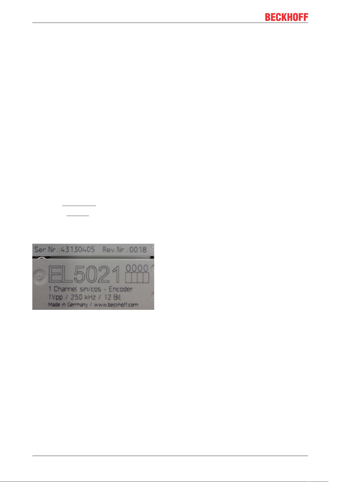
Appendix
Example with
Ser. no.: 12063A02: 12 - production week 12 06 - production year 2006 3A - firmware version 3A 02 hardware version 02
Exceptions can occur in the IP67 area, where the following syntax can be used (see respective device
documentation):
Syntax: D ww yy x y z u
D - prefix designation
ww - calendar week
yy - year
x - firmware version of the bus PCB
y - hardware version of the bus PCB
z - firmware version of the I/O PCB
u - hardware version of the I/O PCB
Example: D.22081501 calendar week 22 of the year 2008 firmware version of bus PCB: 1 hardware version
of bus PCB: 5 firmware version of I/O PCB: 0 (no firmware necessary for this PCB) hardware version of I/O
PCB: 1
Unique serial number/ID, ID number
In addition, in some series each individual module has its own unique serial number.
See also the further documentation in the area
• IP67: EtherCAT Box
• Safety: TwinSafe
• Terminals with factory calibration certificate and other measuring terminals
Examples of markings
Fig.21: EL5021 EL terminal, standard IP20 IO device with serial/ batch number and revision ID (since
2014/01)
EP3752-000048 Version: 1.2
Page 49

Fig.22: EK1100 EtherCAT coupler, standard IP20 IO device with serial/ batch number
Appendix
Fig.23: CU2016 switch with serial/ batch number
Fig.24: EL3202-0020 with serial/ batch number 26131006 and unique ID-number 204418
EP3752-0000 49Version: 1.2
Page 50
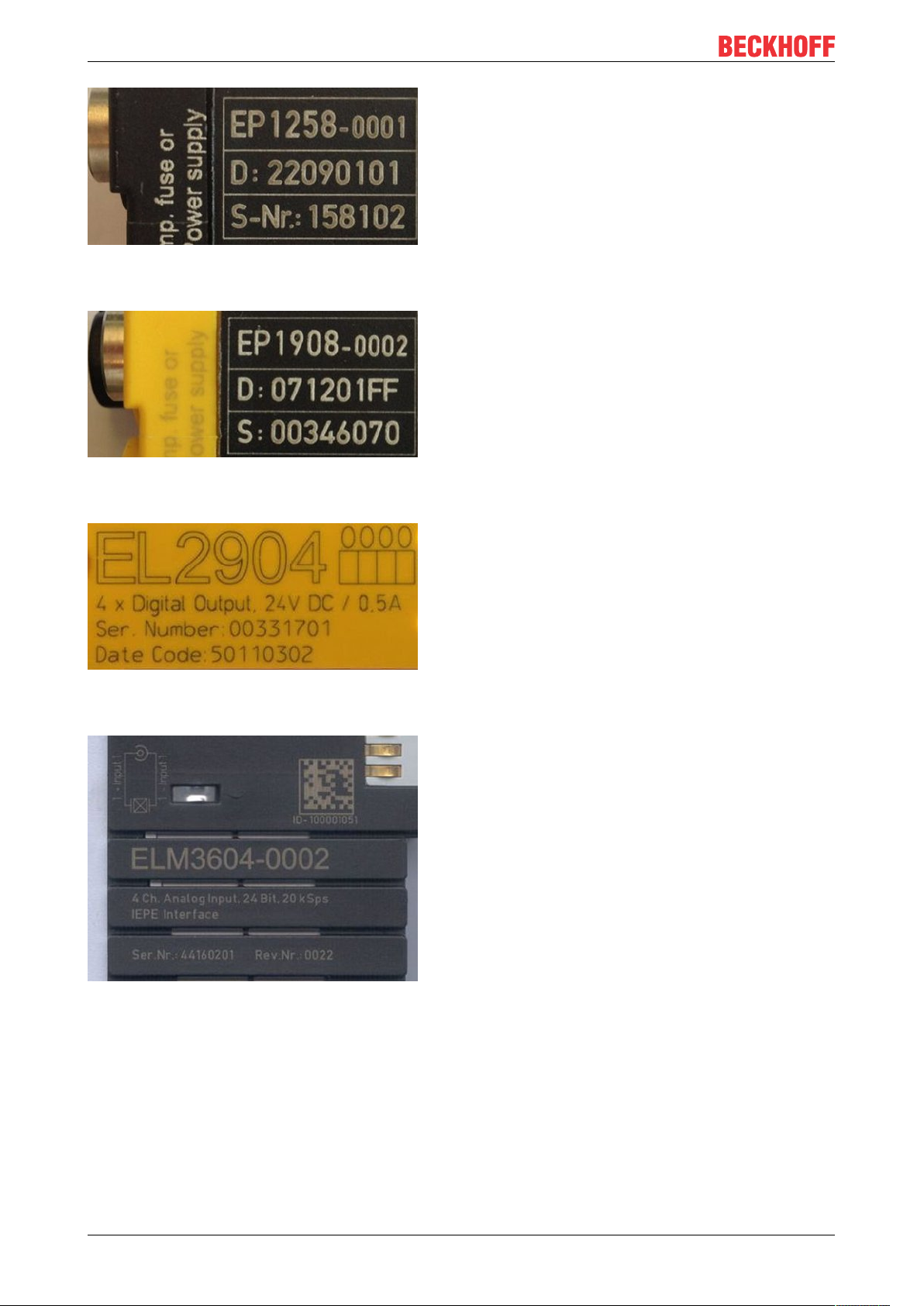
Appendix
Fig.25: EP1258-00001 IP67 EtherCAT Box with batch number/ date code 22090101 and unique serial
number 158102
Fig.26: EP1908-0002 IP67 EtherCAT Safety Box with batch number/ date code 071201FF and unique serial
number 00346070
Fig.27: EL2904 IP20 safety terminal with batch number/ date code 50110302 and unique serial number
00331701
Fig.28: ELM3604-0002 terminal with unique ID number (QR code) 100001051 and serial/ batch number
44160201
EP3752-000050 Version: 1.2
Page 51

Appendix
7.3.1 Beckhoff Identification Code (BIC)
The Beckhoff Identification Code (BIC) is increasingly being applied to Beckhoff products to uniquely identify
the product. The BIC is represented as a Data Matrix Code (DMC, code scheme ECC200), the content is
based on the ANSI standard MH10.8.2-2016.
Fig.29: BIC as data matrix code (DMC, code scheme ECC200)
The BIC will be introduced step by step across all product groups.
Depending on the product, it can be found in the following places:
• on the packaging unit
• directly on the product (if space suffices)
• on the packaging unit and the product
The BIC is machine-readable and contains information that can also be used by the customer for handling
and product management.
Each piece of information can be uniquely identified using the so-called data identifier
(ANSIMH10.8.2-2016). The data identifier is followed by a character string. Both together have a maximum
length according to the table below. If the information is shorter, spaces are added to it. The data under
positions 1 to 4 are always available.
The following information is contained:
EP3752-0000 51Version: 1.2
Page 52

Appendix
Item
Type of
no.
information
1 Beckhoff order
number
2 Beckhoff Traceability
Number (BTN)
3 Article description Beckhoff article
4 Quantity Quantity in packaging
5 Batch number Optional: Year and week
6 ID/serial number Optional: Present-day
7 Variant number Optional: Product variant
...
Explanation Data
Beckhoff order number 1P 8 1P072222
Unique serial number,
see note below
description, e.g.
EL1008
unit, e.g. 1, 10, etc.
of production
serial number system,
e.g. with safety products
number on the basis of
standard products
Number of digits
identifier
S 12 SBTNk4p562d7
1K 32 1KEL1809
Q 6 Q1
2P 14 2P401503180016
51S 12 51S678294104
30P 32 30PF971, 2*K183
incl. data identifier
Example
Further types of information and data identifiers are used by Beckhoff and serve internal processes.
Structure of the BIC
Example of composite information from item 1 to 4 and 6. The data identifiers are marked in red for better
display:
BTN
An important component of the BIC is the Beckhoff Traceability Number (BTN, item no.2). The BTN is a
unique serial number consisting of eight characters that will replace all other serial number systems at
Beckhoff in the long term (e.g. batch designations on IO components, previous serial number range for
safety products, etc.). The BTN will also be introduced step by step, so it may happen that the BTN is not yet
coded in the BIC.
NOTE
This information has been carefully prepared. However, the procedure described is constantly being further
developed. We reserve the right to revise and change procedures and documentation at any time and without prior notice. No claims for changes can be made from the information, illustrations and descriptions in
this information.
EP3752-000052 Version: 1.2
Page 53

Appendix
7.4 Support and Service
Beckhoff and their partners around the world offer comprehensive support and service, making available fast
and competent assistance with all questions related to Beckhoff products and system solutions.
Beckhoff's branch offices and representatives
Please contact your Beckhoff branch office or representative for local support and service on Beckhoff
products!
The addresses of Beckhoff's branch offices and representatives round the world can be found on her internet
pages:
http://www.beckhoff.com
You will also find further documentation for Beckhoff components there.
Beckhoff Headquarters
Beckhoff Automation GmbH & Co. KG
Huelshorstweg 20
33415 Verl
Germany
Phone: +49 5246 963 0
Fax: +49 5246 963 198
e-mail: info@beckhoff.com
Beckhoff Support
Support offers you comprehensive technical assistance, helping you not only with the application of
individual Beckhoff products, but also with other, wide-ranging services:
• support
• design, programming and commissioning of complex automation systems
• and extensive training program for Beckhoff system components
Hotline: +49 5246 963 157
Fax: +49 5246 963 9157
e-mail: support@beckhoff.com
Beckhoff Service
The Beckhoff Service Center supports you in all matters of after-sales service:
• on-site service
• repair service
• spare parts service
• hotline service
Hotline: +49 5246 963 460
Fax: +49 5246 963 479
e-mail: service@beckhoff.com
EP3752-0000 53Version: 1.2
Page 54

Page 55

More Information:
www.beckhoff.com/ep3752-0000/
Beckhoff Automation GmbH & Co. KG
Hülshorstweg 20
33415 Verl
Germany
Phone: +49 5246 9630
info@beckhoff.com
www.beckhoff.com
 Loading...