

Page 1
Documentation | EN
EL72x1-901x
Servo Motor Terminals with OCT and STO, 50 V DC
2020-09-24 | Version: 2.0
Page 2

Page 3

Table of contents
Table of contents
1 Foreword ....................................................................................................................................................7
1.1 Notes on the documentation..............................................................................................................7
1.2 Safety instructions .............................................................................................................................8
1.2.1 Delivery state ..................................................................................................................... 8
1.2.2 Operator's obligation to exercise diligence ........................................................................ 8
1.2.3 Description of instructions.................................................................................................. 9
1.3 Documentation issue status ............................................................................................................10
1.4 Version identification of EtherCAT devices .....................................................................................10
1.4.1 Beckhoff Identification Code (BIC)................................................................................... 15
2 Product overview.....................................................................................................................................17
2.1 Product overview Servomotor terminal with OCT and STO ............................................................17
2.2 Introduction......................................................................................................................................17
2.3 Technical data .................................................................................................................................20
2.4 Technology ......................................................................................................................................22
2.5 Start-up............................................................................................................................................24
3 Basics communication ...........................................................................................................................25
3.1 EtherCAT basics..............................................................................................................................25
3.2 EtherCAT cabling – wire-bound.......................................................................................................25
3.3 General notes for setting the watchdog...........................................................................................26
3.4 EtherCAT State Machine.................................................................................................................28
3.5 CoE Interface...................................................................................................................................30
3.6 Distributed Clock .............................................................................................................................35
4 Installation................................................................................................................................................36
4.1 Safety instructions ...........................................................................................................................36
4.2 Environmental conditions ................................................................................................................36
4.3 Transport / storage ..........................................................................................................................36
4.4 Control cabinet / terminal box..........................................................................................................36
4.5 Instructions for ESD protection........................................................................................................37
4.6 Installation on mounting rails ...........................................................................................................37
4.7 Installation position for operation with or without fan.......................................................................40
4.8 Positioning of passive Terminals .....................................................................................................43
4.9 Installation instructions for enhanced mechanical load capacity .....................................................44
4.10 Connection ......................................................................................................................................45
4.10.1 Connection system .......................................................................................................... 45
4.10.2 Wiring............................................................................................................................... 46
4.11 Example configuration for temperature measurement ....................................................................48
4.12 Shielding concept ............................................................................................................................48
4.13 UL notice - Compact Motion............................................................................................................50
4.14 Notes on current measurements using Hall sensors.......................................................................51
4.15 EL72x1-9014 - LEDs and connection..............................................................................................53
5 Commissioning........................................................................................................................................57
5.1 TwinCAT Quick Start .......................................................................................................................57
5.1.1 TwinCAT2 ....................................................................................................................... 60
EL72x1-901x 3Version: 2.0
Page 4

Table of contents
5.1.2 TwinCAT 3 ....................................................................................................................... 70
5.2 TwinCAT Development Environment ..............................................................................................83
5.2.1 Installation of the TwinCAT real-time driver..................................................................... 84
5.2.2 Notes regarding ESI device description........................................................................... 89
5.2.3 TwinCAT ESI Updater ..................................................................................................... 93
5.2.4 Distinction between Online and Offline............................................................................ 93
5.2.5 OFFLINE configuration creation ...................................................................................... 94
5.2.6 ONLINE configuration creation ........................................................................................ 99
5.2.7 EtherCAT subscriber configuration................................................................................ 107
5.3 Start-up and parameter configuration............................................................................................116
5.3.1 Integration into the NC configuration ............................................................................. 116
5.3.2 Settings with the Drive Manager.................................................................................... 120
5.3.3 Settings in the CoE register ........................................................................................... 125
5.3.4 NC settings .................................................................................................................... 129
5.3.5 Application example....................................................................................................... 135
5.3.6 Commissioning without NC, status word/control word................................................... 140
5.3.7 Settings for the automatic configuration ........................................................................ 144
5.3.8 Configuring the limit switch ........................................................................................... 146
5.3.9 Homing .......................................................................................................................... 147
5.3.10 Touch Probe .................................................................................................................. 150
5.4 Operation modes ...........................................................................................................................153
5.4.1 Overview........................................................................................................................ 153
5.4.2 CSV ............................................................................................................................... 153
5.4.3 CST................................................................................................................................ 157
5.4.4 CSTCA........................................................................................................................... 160
5.4.5 CSP ............................................................................................................................... 164
5.5 Profile MDP 742 or DS 402 ...........................................................................................................168
5.6 MDP742 process data ...................................................................................................................168
5.7 DS402 process data ......................................................................................................................172
6 Integrated safety....................................................................................................................................177
6.1 Safety regulations..........................................................................................................................177
6.2 Description of product and function ...............................................................................................177
6.2.1 Intended use .................................................................................................................. 177
6.2.2 Dimensions .................................................................................................................... 178
6.2.3 TwinSAFE reaction times .............................................................................................. 179
6.2.4 Application example for STO function (Cat. 3, PL d) ..................................................... 181
6.3 Maintenance ..................................................................................................................................187
6.4 Service life .....................................................................................................................................187
7 Object description and parameterization............................................................................................189
7.1 EL72x1-9014 (MDP742)................................................................................................................189
7.1.1 Restore object................................................................................................................ 189
7.1.2 Configuration data ......................................................................................................... 189
7.1.3 Configuration data (vendor-specific).............................................................................. 196
7.1.4 Command object............................................................................................................ 196
7.1.5 Input data....................................................................................................................... 196
EL72x1-901x4 Version: 2.0
Page 5

Table of contents
7.1.6 Output data .................................................................................................................... 198
7.1.7 Information / diagnosis data .......................................................................................... 200
7.1.8 Standard objects............................................................................................................ 203
7.2 EL72x1-9014 (DS402)...................................................................................................................212
7.2.1 Configuration data ......................................................................................................... 213
7.2.2 Configuration data (vendor-specific).............................................................................. 218
7.2.3 Command object ........................................................................................................... 218
7.2.4 Input/output data............................................................................................................ 219
7.2.5 Information / diagnosis data .......................................................................................... 224
7.2.6 Standard objects............................................................................................................ 227
8 Error correction .....................................................................................................................................234
8.1 Diagnostics – basic principles of diag messages ..........................................................................234
9 Appendix ................................................................................................................................................244
9.1 EtherCAT AL Status Codes...........................................................................................................244
9.2 Firmware compatibility...................................................................................................................244
9.3 Firmware Update EL/ES/EM/ELM/EPxxxx ....................................................................................245
9.3.1 Device description ESI file/XML..................................................................................... 246
9.3.2 Firmware explanation .................................................................................................... 249
9.3.3 Updating controller firmware *.efw................................................................................. 250
9.3.4 FPGA firmware *.rbf....................................................................................................... 252
9.3.5 Simultaneous updating of several EtherCAT devices.................................................... 256
9.4 Restoring the delivery state ...........................................................................................................257
9.5 Certificates.....................................................................................................................................258
9.6 Support and Service ......................................................................................................................259
EL72x1-901x 5Version: 2.0
Page 6

Table of contents
EL72x1-901x6 Version: 2.0
Page 7

Foreword
1 Foreword
1.1 Notes on the documentation
Intended audience
This description is only intended for the use of trained specialists in control and automation engineering who
are familiar with the applicable national standards.
It is essential that the following notes and explanations are followed when installing and commissioning
these components.
The responsible staff must ensure that the application or use of the products described satisfy all the
requirements for safety, including all the relevant laws, regulations, guidelines and standards.
Origin of the document
This original documentation is written in German. All other languages are derived from the German original.
Currentness
Please check whether you are using the current and valid version of this document. The current version can
be downloaded from the Beckhoff homepage at http://www.beckhoff.com/english/download/twinsafe.htm.
In case of doubt, please contact Technical Support [}259].
Product features
Only the product features specified in the current user documentation are valid. Further information given on
the product pages of the Beckhoff homepage, in emails or in other publications is not authoritative.
Disclaimer
The documentation has been prepared with care. The products described are subject to cyclical revision. For
that reason the documentation is not in every case checked for consistency with performance data,
standards or other characteristics. We reserve the right to revise and change the documentation at any time
and without prior announcement. No claims for the modification of products that have already been supplied
may be made on the basis of the data, diagrams and descriptions in this documentation.
Trademarks
Beckhoff®, TwinCAT®, EtherCAT®, EtherCATG®, EtherCATG10®, EtherCATP®, SafetyoverEtherCAT®,
TwinSAFE®, XFC®, XTS® and XPlanar® are registered trademarks of and licensed by Beckhoff Automation
GmbH. Other designations used in this publication may be trademarks whose use by third parties for their
own purposes could violate the rights of the owners.
Patent Pending
The EtherCAT Technology is covered, including but not limited to the following patent applications and
patents: EP1590927, EP1789857, EP1456722, EP2137893, DE102015105702 with corresponding
applications or registrations in various other countries.
EL72x1-901x 7Version: 2.0
Page 8

Foreword
EtherCAT® and Safety over EtherCAT® are registered trademarks and patented technologies, licensed by
Beckhoff Automation GmbH, Germany.
Copyright
© Beckhoff Automation GmbH & Co. KG, Germany.
The reproduction, distribution and utilization of this document as well as the communication of its contents to
others without express authorization are prohibited.
Offenders will be held liable for the payment of damages. All rights reserved in the event of the grant of a
patent, utility model or design.
Delivery conditions
In addition, the general delivery conditions of the company Beckhoff Automation GmbH & Co. KG apply.
1.2 Safety instructions
1.2.1 Delivery state
All the components are supplied in particular hardware and software configurations appropriate for the
application. Modifications to hardware or software configurations other than those described in the
documentation are not permitted, and nullify the liability of Beckhoff Automation GmbH & Co. KG.
1.2.2 Operator's obligation to exercise diligence
The operator must ensure that
• the TwinSAFE products are only used as intended (see chapter Product description);
• the TwinSAFE products are only operated in sound condition and in working order.
• the TwinSAFE products are operated only by suitably qualified and authorized personnel.
• the personnel is instructed regularly about relevant occupational safety and environmental protection
aspects, and is familiar with the operating instructions and in particular the safety instructions contained
herein.
• the operating instructions are in good condition and complete, and always available for reference at the
location where the TwinSAFE products are used.
• none of the safety and warning notes attached to the TwinSAFE products are removed, and all notes
remain legible.
EL72x1-901x8 Version: 2.0
Page 9
1.2.3 Description of instructions
In these operating instructions the following instructions are used.
These instructions must be read carefully and followed without fail!
DANGER
Serious risk of injury!
Failure to follow this safety instruction directly endangers the life and health of persons.
WARNING
Risk of injury!
Failure to follow this safety instruction endangers the life and health of persons.
CAUTION
Personal injuries!
Failure to follow this safety instruction can lead to injuries to persons.
NOTE
Damage to the environment/equipment or data loss
Failure to follow this instruction can lead to environmental damage, equipment damage or data loss.
Foreword
Tip or pointer
This symbol indicates information that contributes to better understanding.
EL72x1-901x 9Version: 2.0
Page 10

Foreword
1.3 Documentation issue status
Version Comment
2.0 • Update chapter “Introduction”
• Update chapter “Technical data”
• Update chapter “Technology”
• Update chapter “LEDs and connection”
• Update revision status
• Update structure
1.9 • Note for fuse protection of the supply voltage added
• Update revision status
• Update structure
1.8 • Update chapter “Object description”
• Update structure
1.7 • Update chapter “Introduction”
• Update structure
1.6 • EL7221-901x added
1.5 • Addenda chapter “UL notice – Compact motion”
• Update revision status
• Update structure
1.4 • Update chapter “Object description and parameterization”
• Update revision status
• Update structure
1.3 • Update revision status
• Update structure
1.2 • Update chapter “Technical Data”
• Update structure
1.1 • Commissioning: chapter Quickstart added
• TwinCAT Development Environment: TwinCAT 3 added
1.0 • First published (only German)
0.1 - 0.5 • Preliminary versions (for internal use only)
1.4 Version identification of EtherCAT devices
Designation
A Beckhoff EtherCAT device has a 14-digit designation, made up of
• family key
• type
• version
• revision
EL72x1-901x10 Version: 2.0
Page 11

Foreword
Example Family Type Version Revision
EL3314-0000-0016 EL terminal
(12 mm, nonpluggable connection
level)
ES3602-0010-0017 ES terminal
(12 mm, pluggable
connection level)
CU2008-0000-0000 CU device 2008 (8-port fast ethernet switch) 0000 (basic type) 0000
Notes
• The elements mentioned above result in the technical designation. EL3314-0000-0016 is used in the
example below.
• EL3314-0000 is the order identifier, in the case of “-0000” usually abbreviated to EL3314. “-0016” is the
EtherCAT revision.
• The order identifier is made up of
- family key (EL, EP, CU, ES, KL, CX, etc.)
- type (3314)
- version (-0000)
• The revision -0016 shows the technical progress, such as the extension of features with regard to the
EtherCAT communication, and is managed by Beckhoff.
In principle, a device with a higher revision can replace a device with a lower revision, unless specified
otherwise, e.g. in the documentation.
Associated and synonymous with each revision there is usually a description (ESI, EtherCAT Slave
Information) in the form of an XML file, which is available for download from the Beckhoff web site.
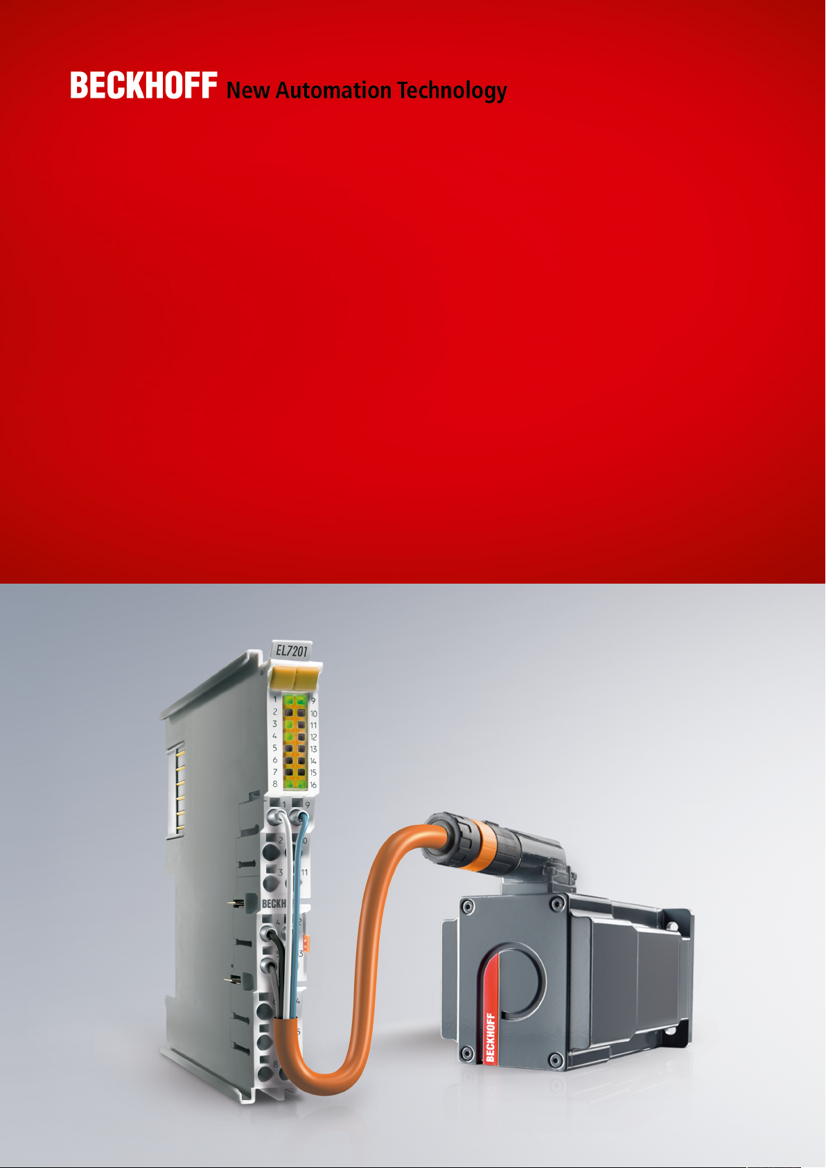
From 2014/01 the revision is shown on the outside of the IP20 terminals, see Fig. “EL5021 EL terminal,
standard IP20 IO device with batch number and revision ID (since 2014/01)”.
• The type, version and revision are read as decimal numbers, even if they are technically saved in
hexadecimal.
3314 (4-channel thermocouple
terminal)
3602 (2-channel voltage
measurement)
0000 (basic type) 0016
0010 (highprecision version)
0017
Identification number
Beckhoff EtherCAT devices from the different lines have different kinds of identification numbers:
Production lot/batch number/serial number/date code/D number
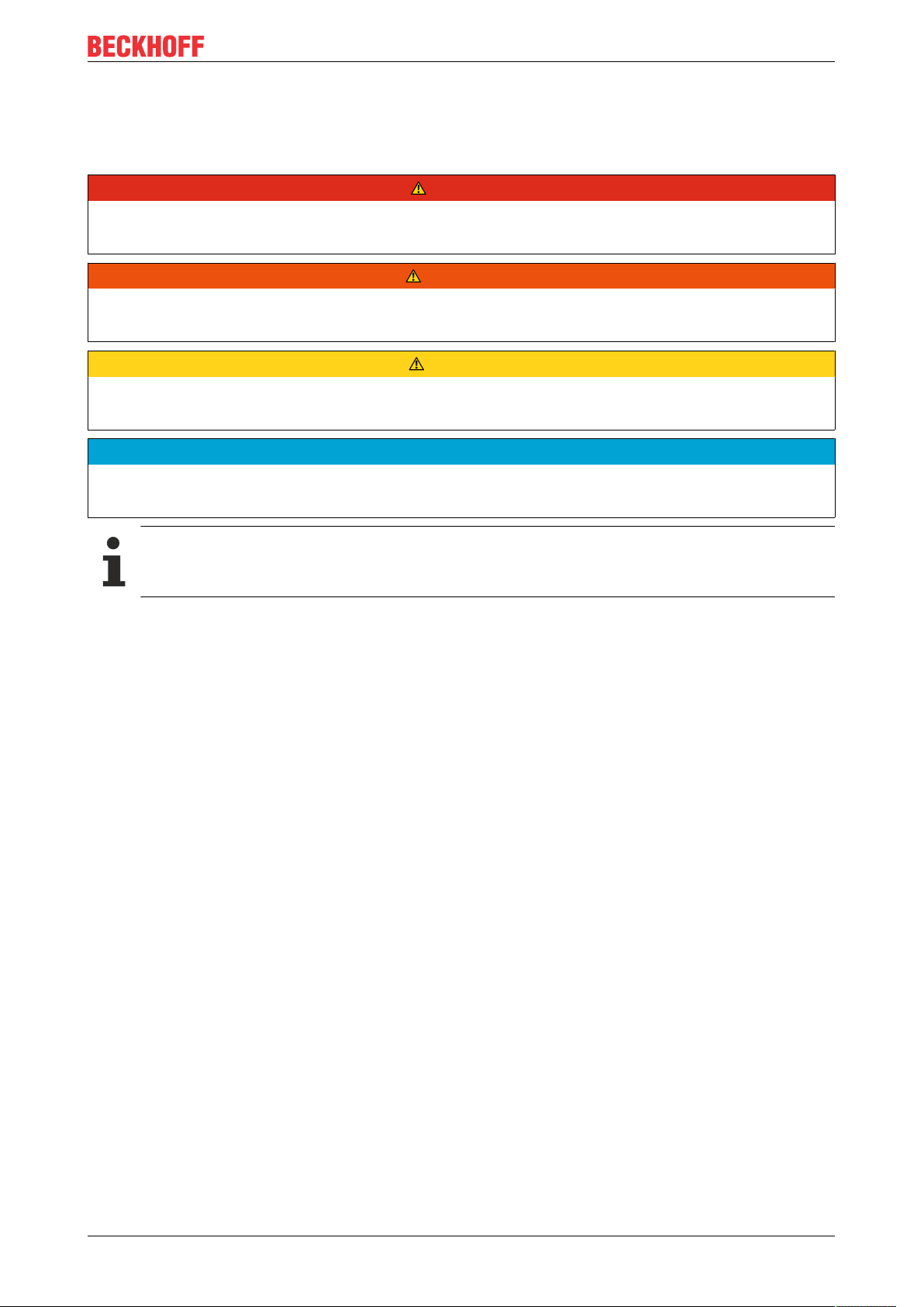
The serial number for Beckhoff IO devices is usually the 8-digit number printed on the device or on a sticker.
The serial number indicates the configuration in delivery state and therefore refers to a whole production
batch, without distinguishing the individual modules of a batch.
Structure of the serial number: KKYYFFHH
KK - week of production (CW, calendar week)
YY - year of production
FF - firmware version
HH - hardware version
Example with
Ser. no.: 12063A02: 12 - production week 12 06 - production year 2006 3A - firmware version 3A 02 hardware version 02
Exceptions can occur in the IP67 area, where the following syntax can be used (see respective device
documentation):
Syntax: D ww yy x y z u
D - prefix designation
ww - calendar week
yy - year
x - firmware version of the bus PCB
EL72x1-901x 11Version: 2.0
Page 12
Foreword
y - hardware version of the bus PCB
z - firmware version of the I/O PCB
u - hardware version of the I/O PCB
Example: D.22081501 calendar week 22 of the year 2008 firmware version of bus PCB: 1 hardware version
of bus PCB: 5 firmware version of I/O PCB: 0 (no firmware necessary for this PCB) hardware version of I/O
PCB: 1
Unique serial number/ID, ID number
In addition, in some series each individual module has its own unique serial number.
See also the further documentation in the area
• IP67: EtherCAT Box
• Safety: TwinSafe
• Terminals with factory calibration certificate and other measuring terminals
Examples of markings
Fig.1: EL5021 EL terminal, standard IP20 IO device with serial/ batch number and revision ID (since
2014/01)
Fig.2: EK1100 EtherCAT coupler, standard IP20 IO device with serial/ batch number
EL72x1-901x12 Version: 2.0
Page 13
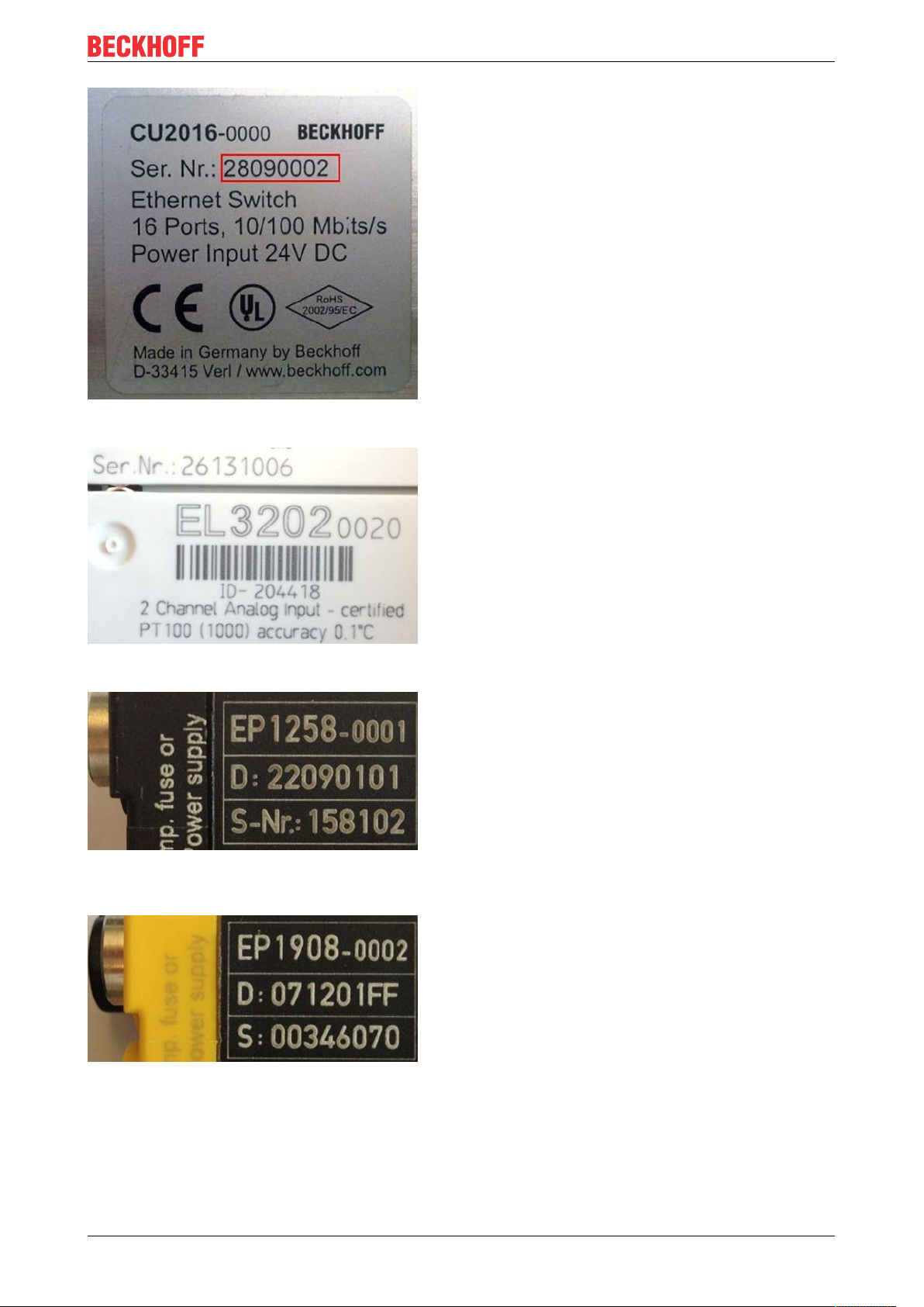
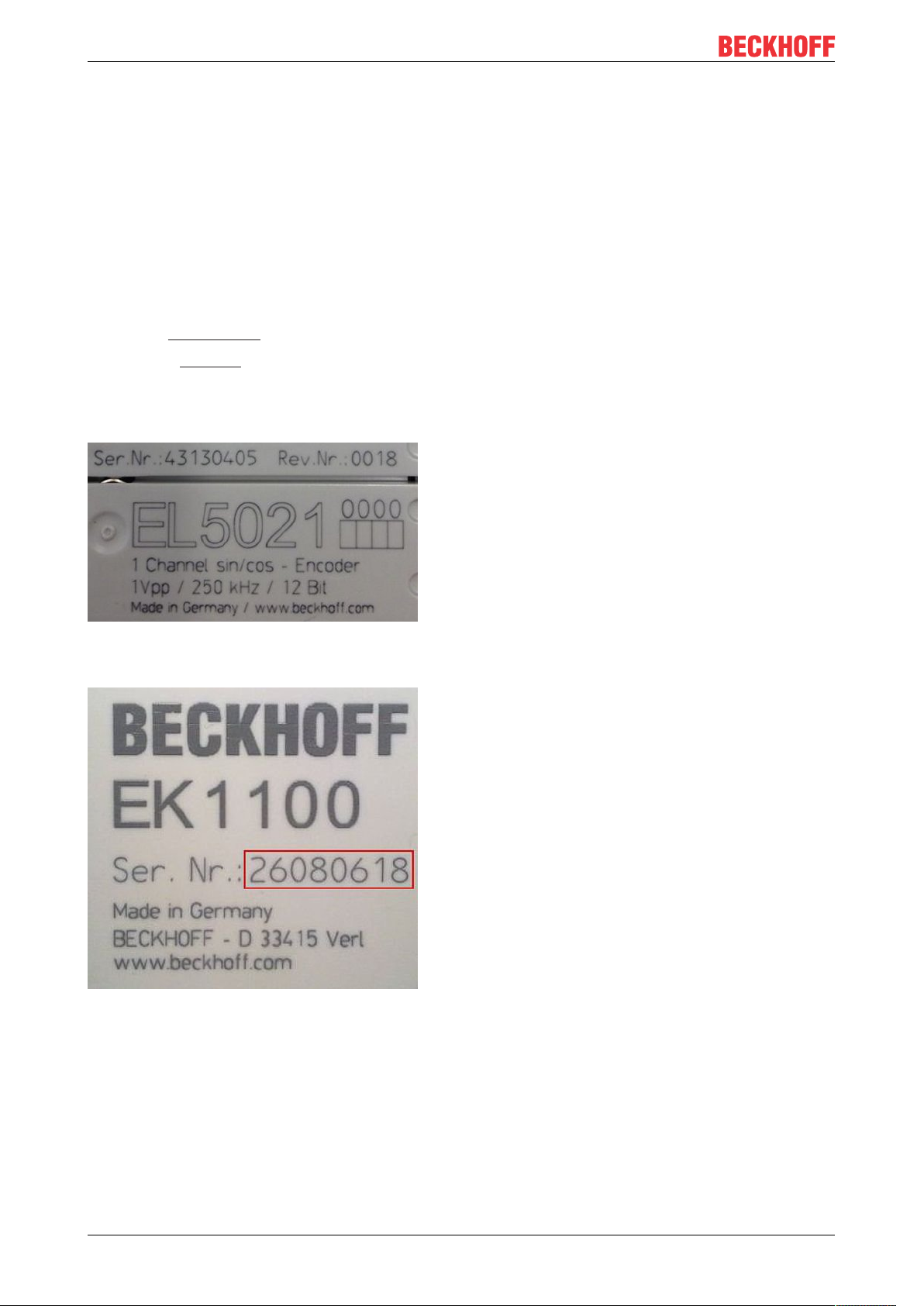
Fig.3: CU2016 switch with serial/ batch number
Foreword
Fig.4: EL3202-0020 with serial/ batch number 26131006 and unique ID-number 204418
Fig.5: EP1258-00001 IP67 EtherCAT Box with batch number/ date code 22090101 and unique serial
number 158102
Fig.6: EP1908-0002 IP67 EtherCAT Safety Box with batch number/ date code 071201FF and unique serial
number 00346070
EL72x1-901x 13Version: 2.0
Page 14
Foreword
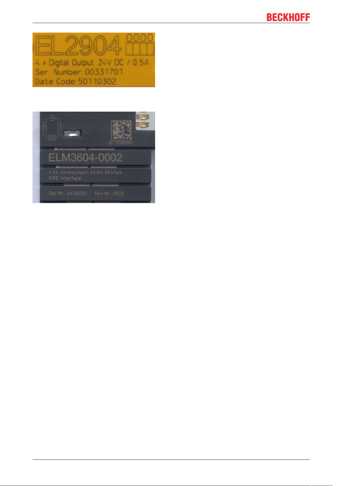
Fig.7: EL2904 IP20 safety terminal with batch number/ date code 50110302 and unique serial number
00331701
Fig.8: ELM3604-0002 terminal with unique ID number (QR code) 100001051 and serial/ batch number
44160201
EL72x1-901x14 Version: 2.0
Page 15
Foreword
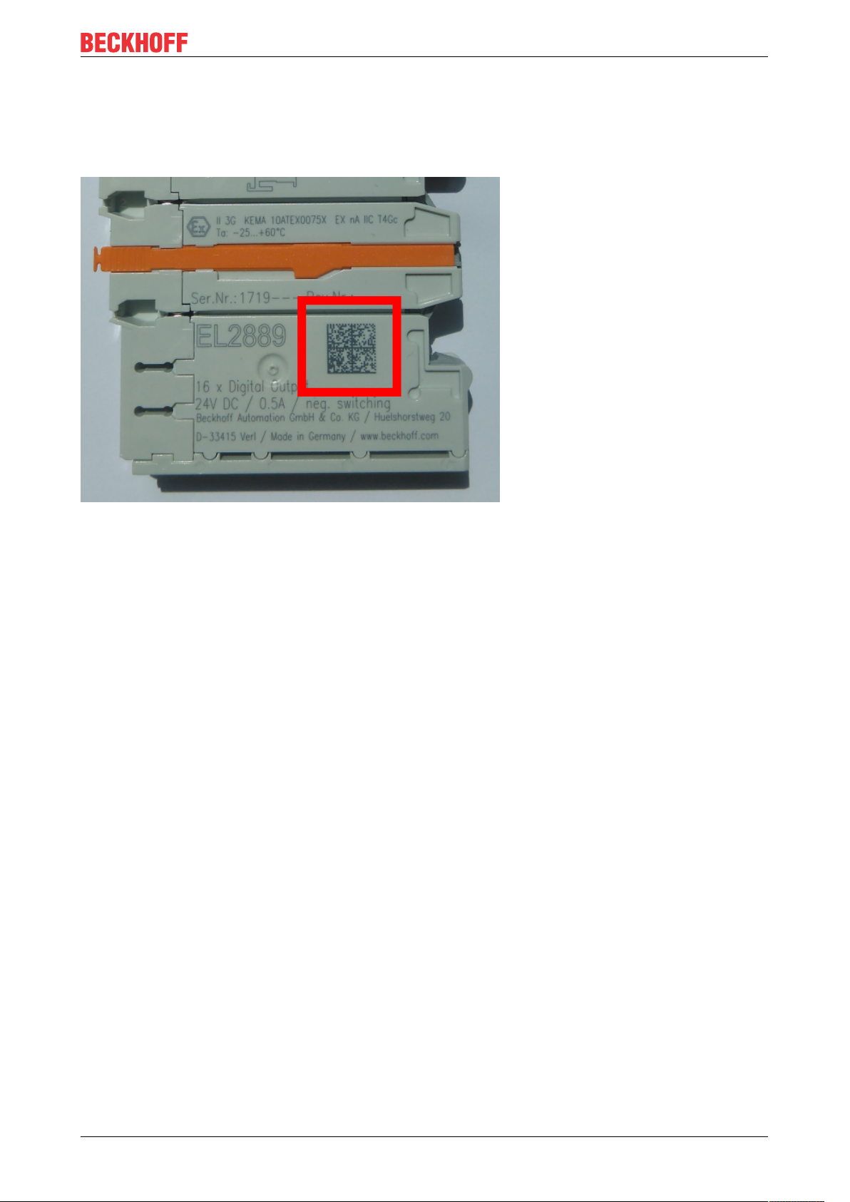
1.4.1 Beckhoff Identification Code (BIC)
The Beckhoff Identification Code (BIC) is increasingly being applied to Beckhoff products to uniquely identify
the product. The BIC is represented as a Data Matrix Code (DMC, code scheme ECC200), the content is
based on the ANSI standard MH10.8.2-2016.
Fig.9: BIC as data matrix code (DMC, code scheme ECC200)
The BIC will be introduced step by step across all product groups.
Depending on the product, it can be found in the following places:
• on the packaging unit
• directly on the product (if space suffices)
• on the packaging unit and the product
The BIC is machine-readable and contains information that can also be used by the customer for handling
and product management.
Each piece of information can be uniquely identified using the so-called data identifier
(ANSIMH10.8.2-2016). The data identifier is followed by a character string. Both together have a maximum
length according to the table below. If the information is shorter, spaces are added to it. The data under
positions 1 to 4 are always available.
The following information is contained:
EL72x1-901x 15Version: 2.0
Page 16

Foreword
Item
Type of
no.
information
1 Beckhoff order
number
2 Beckhoff Traceability
Number (BTN)
3 Article description Beckhoff article
4 Quantity Quantity in packaging
5 Batch number Optional: Year and week
6 ID/serial number Optional: Present-day
7 Variant number Optional: Product variant
...
Explanation Data
Beckhoff order number 1P 8 1P072222
Unique serial number,
see note below
description, e.g.
EL1008
unit, e.g. 1, 10, etc.
of production
serial number system,
e.g. with safety products
number on the basis of
standard products
Number of digits
identifier
S 12 SBTNk4p562d7
1K 32 1KEL1809
Q 6 Q1
2P 14 2P401503180016
51S 12 51S678294104
30P 32 30PF971, 2*K183
incl. data identifier
Example
Further types of information and data identifiers are used by Beckhoff and serve internal processes.
Structure of the BIC
Example of composite information from item 1 to 4 and 6. The data identifiers are marked in red for better
display:
BTN
An important component of the BIC is the Beckhoff Traceability Number (BTN, item no.2). The BTN is a
unique serial number consisting of eight characters that will replace all other serial number systems at
Beckhoff in the long term (e.g. batch designations on IO components, previous serial number range for
safety products, etc.). The BTN will also be introduced step by step, so it may happen that the BTN is not yet
coded in the BIC.
NOTE
This information has been carefully prepared. However, the procedure described is constantly being further
developed. We reserve the right to revise and change procedures and documentation at any time and without prior notice. No claims for changes can be made from the information, illustrations and descriptions in
this information.
EL72x1-901x16 Version: 2.0
Page 17
Product overview
2 Product overview
2.1 Product overview Servomotor terminal with OCT and STO
EL7201-9014 [}17] servo motor terminal with OCT and STO, 48 VDC, 2.8 A
EL7201-9015 [}17] servo motor terminal with OCT and STO, 48 VDC, 2.8 A
EL7211-9014 [}17] servo motor terminal with OCT and STO, 48 VDC, 4.5 A
EL7211-9015 [}17] servo motor terminal with OCT and STO, 48 VDC, 4.5 A
EL7221-9014 [}17] servo motor terminal with OCT and STO, 48 VDC, 7…8 A
EL7221-9015 [}17] servo motor terminal with OCT and STO, 48 VDC, 7…8 A
2.2 Introduction
, MDP742 profile
rms
, DS402 profile
rms
, MDP742 profile
rms
, DS402 profile
rms
, MDP742 profile
rms
, DS402 profile
rms
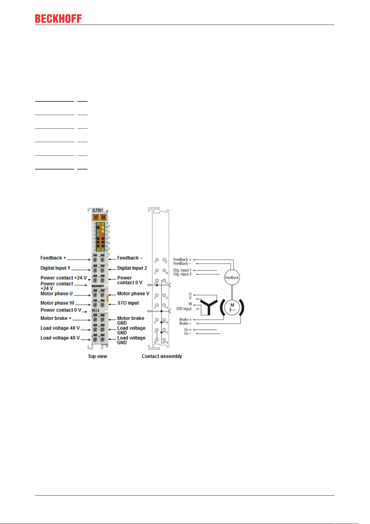
Fig.10: EL7201-901x
EL72x1-901x 17Version: 2.0
Page 18
Product overview
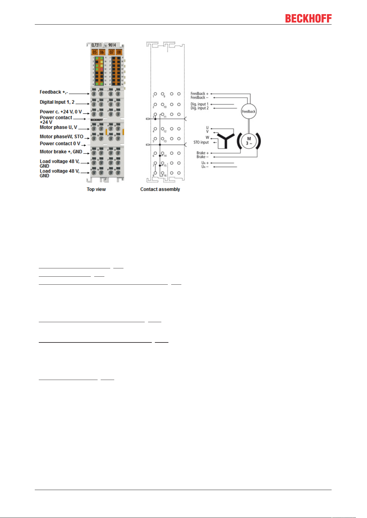
Fig.11: EL7211-901x, EL7221-901x
Quick links
Connection instructions
Chapter "Mounting and wiring",
- LEDs and pin assignment [}53]
- Shielding concept [}48]
- Notes on current measurement via Hall sensor [}51]
Configuration instructions
Chapter "Commissioning",
- Configuration of the main parameters [}116]
Chapter "Configuration with the TwinCAT System Manager",
- Object description and parameterization [}189]
Application example
Chapter "Commissioning",
- Application example [}135]
Servo motor terminals with OCT and STO input
The servo-motor EtherCAT terminals EL7201-901x (48VDC, 2.8A
EL7221-901x (48VDC, 7…8A
) with integrated absolute value interface, offer high servo performance in a
rms
), EL7211-901x (48VDC, 4.5A
rms
rms
) and
very compact design. The EL72x1-901x were designed for the motor types of the AM81xx series from
Beckhoff Automation.
The fast control technology, based on field-orientated current and PI speed control, supports fast and highly
dynamic positioning tasks. The monitoring of numerous parameters, such as overvoltage and undervoltage,
overcurrent, terminal temperature or motor load via the calculation of a I²T model, offers maximum
operational reliability.
EL72x1-901x18 Version: 2.0
Page 19

Product overview
EtherCAT, as a high-performance system communication, and CAN-over-EtherCAT (CoE), as the
application layer, enable ideal interfacing with PC-based control technology.
The latest power semiconductors guarantee minimum power loss and enable feedback into the DC link when
braking.
The LEDs indicate status, warning and error messages as well as possibly active limitations.
With the One Cable Technology (OCT) the encoder cable is omitted by transmitting the signals of the
encoder digitally via the existing motor cable. The option to read the electronic type plates of suitable motors
from the AM81xx series enables a plug-and-play solution for maximum convenience during commissioning.
The EL72x1-901x provides an STO input with which the motor connected to the terminal can be switched
torque-free. This STO input is connected to a safe output of an EL2904.
Performance Level d, Category 3 according to DIN EN ISO 13849-1:2015 is attained for the SFO safety
function of the EL72x1-901x together with an EL2904.
Recommended TwinCAT version
In order to be able to utilize the full power of the EL72x1-901x, we recommend using the
EL72x1-901x with TwinCAT 2.11 R3 or higher!
Mandatory hardware
The EL72x1-901x must be operated with a real-time capable computer and distributed clocks!
Approved motors
The EL72x1-901x may be operated only with the following Beckhoff motors.
- AM8111-xF1x, AM8112-xF1x, AM8113-xF1x, AM8121-xF1x, AM8122-xF1x, AM8131-xF1x,
AM8132-xJ1x, AM8133-xJ1x, AM8141-xJ1x
- AM8111-xF2x, AM8112-xF2x, AM8113-xF2x, AM8121-xF2x, AM8122-xF2x, AM8131-xF2x,
AM8132-xJ2x, AM8133-xJ2x, AM8141-xJ2x
Operation of the EL7221-901x with fan cartridge ZB8610
Due to the increased thermal load, the EL7221-091x must only be operated in conjunction with the
fan cartridge ZB8610 in order to avoid malfunctions.
EL72x1-901x 19Version: 2.0
Page 20

Product overview
2.3 Technical data
EL72x1-901x20 Version: 2.0
Page 21

Product overview
Technical data EL7201-901x EL7211-901x EL7221-901x
Number of outputs 3 motor phases, 2 motor holding brake
Number of inputs 2 (4) DC link voltage, 2 absolute feedback,
DC link supply voltage 8...48V
Supply voltage 24VDC via the power contacts / via the E-bus
Output current
Peak current 5.7A
Rated power
Motor holding brake output voltage 24V (+ 6 %, - 10 %)
Max. motor holding brake output cur-
rent
Load type permanently excited synchronous motors, inductive
PWM switching frequency 16kHz
Current controller frequency double PWM switching frequency
Velocity controller frequency 16 kHz
Diagnostic LED Status, warning, errors and limits
Power loss typ. 1.6W
Current consumption via E-bus typ. 120 mA
Current consumption from the 24 V typ. 55 mA + holding brake
Supports NoCoeStorage [}30] function
Reverse voltage protection 24 V power supply yes, through the body diode of the overvoltage protection device
Fuse protection
(to be carried out by the user)
Electrical isolation 500 V (E-bus/signal voltage)
Possible EtherCAT cycle times Multiple of 125µs
Configuration no address setting required
Weight approx. 60 g approx. 95 g
Permissible ambient temperature
range during operation
Permissible ambient temperature
range during storage
Permissible relative humidity 95%, no condensation
Dimensions (W x H x D) approx. 15 mm x 100 mm x 70
Mounting [}37]
Vibration/shock resistance conforms to EN 60068-2-6 / EN 60068-2-27,
EMC immunity / emission conforms to EN 61000-6-2 / EN 61000-6-4
EMC category Category C3 - standard
Protection class IP20
Installation position
Approval CE
2 digital inputs. 1 STO input
DC
2.8A
(without fan cartridge
rms
ZB8610)
4.5A
(with fan cartridge
rms
ZB8610)
for 1 second 2.8A
rms
(without fan cartridge ZB8610)
9A
for 1 second 2.8A
rms
4.5A
rms
7A
up to 55°C (with fan car-
rms
tridge ZB8610)
8A
up to 45°C (with fan car-
rms
tridge ZB8610)
9A
rms
for 1 second
rms
16A
for 1 second (with fan
rms
cartridge ZB8610)
rms
(with fan cartridge ZB8610)
170 W (without fan cartridge
ZB8610)
276 W (with fan cartridge
ZB8610)
276 W
428 W up to 55°C (with fan
cartridge ZB8610)
490 W up to 45°C (with fan
cartridge ZB8610)
max. 0.5 A
(series AM81xx)
Yes
50 V power supply yes, through the body diode of the overvoltage protection device
24 V power supply 10 A
50 V power supply 10 A
configuration via TwinCAT System Manager
0°C ... + 55°C
-25°C ... + 85°C
approx. 27 mm x 100 mm x 70
mm (width aligned: 12 mm)
mm (width aligned: 24 mm)
on 35 mm mounting rail conforms to EN 60715
see also installation instructions [}44] for enhanced mechanical load capacity
according to IEC/EN 61800-3
Category C2, C1 - auxiliary filter required
without fan cartridge ZB8610: standard installing position
with fan cartridge ZB8610: standard installing position, other installing positions (example 1 & 2)
see notice [}40]!
cULus [}50]
TÜV-Süd [}258]
EL72x1-901x 21Version: 2.0
Page 22
Product overview
2.4 Technology
The very compact EL72x1-xxxx servomotor terminal integrates a complete servo drive for servomotors up to
276W.
Servomotor
The servomotor is an electrical motor. Together with a servo amplifier the servomotor forms a servo drive.
The servomotor is operated in a closed control loop with position, torque or speed control.
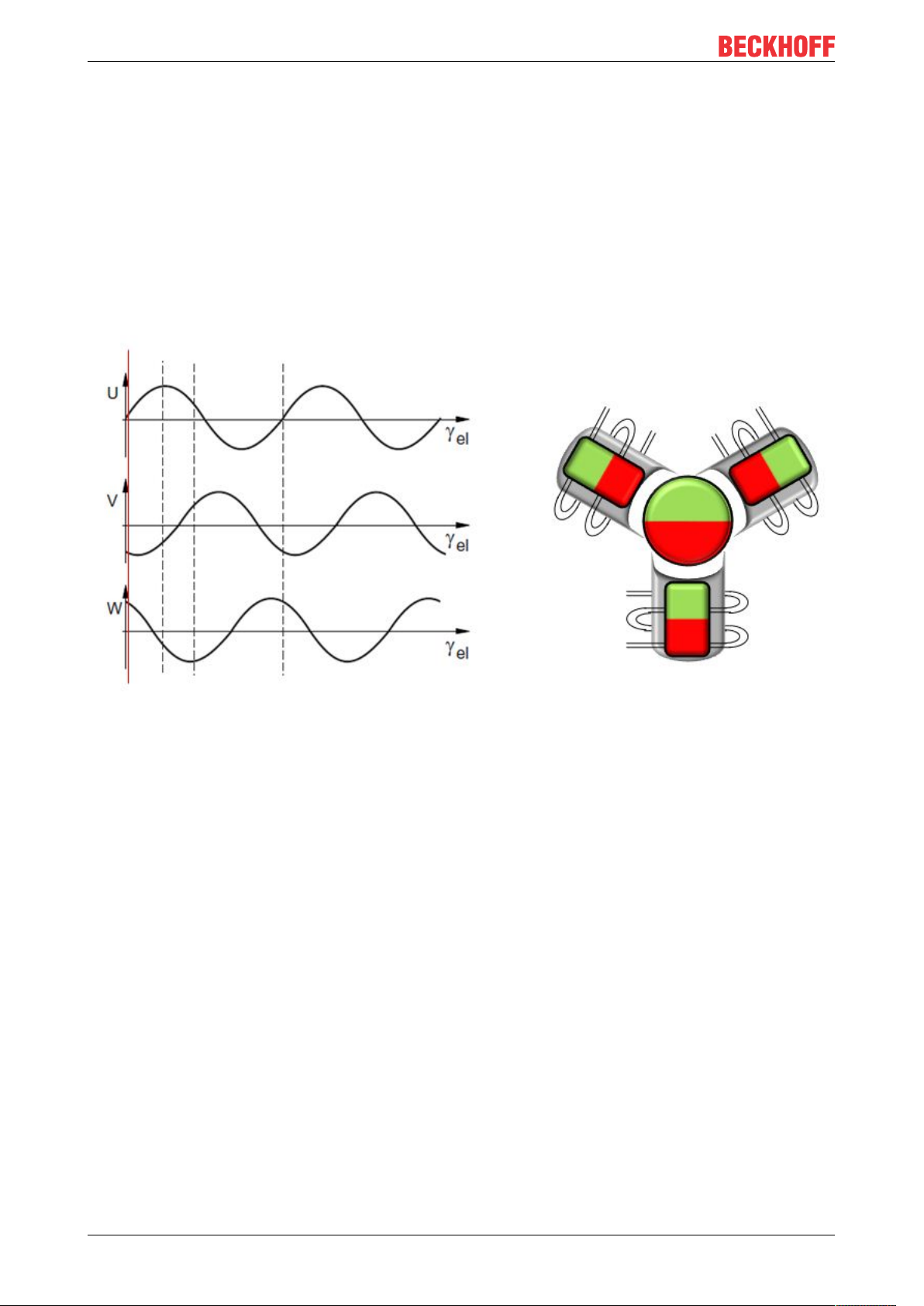
The servo terminal EL72x1-xxxx supports control of permanent magnet synchronous motors. These consist
of 3 coils which are offset by 120° and a permanent magnet rotor.
Fig.12: Three synchronous motor coils, each offset by 120°
Servomotors particularly demonstrate their advantages in highly dynamic and precise positioning
applications:
• very high positioning accuracy in applications where maximum precision is required through integrated
position feedback
• high efficiency and high acceleration capacity
• servomotors are overload-proof and therefore have far greater dynamics than stepper motors, for
example.
• load-independent high torque right up to the higher speed ranges
• maintenance requirements reduced to a minimum
The EtherCAT servomotor terminal offers users the option to configure compact and cost-effective systems
without having to give up the benefits of a servomotor.
The Beckhoff servo terminal
The EL72x1-xxxx is a fully capable servo drive for direct connection to servomotors in the lower performance
range. There is no need for further modules or cabling to make a connection to the control system. This
results in a very compact control system solution. The E-Bus connection of the EL72x1-xxxx makes the full
functionality of EtherCAT available to the user. This includes in particular the short cycle time, low jitter,
simultaneity and easy diagnostics provided by EtherCAT. With this performance from EtherCAT the
dynamics that a servomotor can achieve can be used optimally.
EL72x1-901x22 Version: 2.0
Page 23

Product overview
With a rated voltage up to 48VDC and a rated current of up to 4.5A, this enables the user to operate a
servomotor with a power of up to 276W. Permanent magnet synchronous motors with a rated current of up
to 4.5A can be connected as loads. The monitoring of numerous parameters, such as overvoltage and
undervoltage, overcurrent, terminal temperature or motor load, offers maximum operational reliability.
Modern power semiconductors guarantee minimum power loss and enable feedback into the DC link when
braking.
With the integration of a complete servo drive into a standard EL7201 EtherCAT Terminal only 12mm wide,
Beckhoff is setting new standards in matters of size. This small manufactured size is possible thanks to the
latest semiconductor technology and the resulting very high power factor. And yet, despite the small
dimensions, nothing has to be sacrificed.
The integrated fast control technology, with a field-orientated current and PI speed control, supports highly
dynamic positioning tasks. Apart from the direct connection of motor and resolver, the connection of a motor
holding brake is also possible.
The EL72x1-xx1x EtherCAT terminal has two digital inputs that can be used for the “Touch Probe” function.
The status of the inputs can be read by “Select Info Data” (MDP742 profile and DS402 profile).
Connection to the control system
A further big advantage of the EL72x1-xxxx is the easy incorporation into the control solution. The complete
integration into the control system simplifies commissioning and parameterization. As with all the other
Beckhoff terminals, the EL72x1-xxxx is simply inserted into the terminal network. Then the full terminal
network can be scanned by the TwinCAT System Manager or manually added by the application engineer.
In the System Manager the EL72x1-xxxx can be linked with the TwinCAT NC and parameterized.
Scalable motion solution
The servo terminal complements the product range of compact drive technology for Beckhoff I/O systems
that are available for stepper motors, AC and DC motors. With the EL72x1-xxxx, the range of servo drives
becomes even more finely scalable: from the miniature servo drive up to 170 W in the EtherCAT Terminal
through to the AX5000 servo drive with 118 KW, Beckhoff offers a wide range including the servomotors.
The AM81xx series was specially developed for the servomotor terminal EL72x1-xxxx.
One Cable Technology (OCT)
In the servomotors from the AM8100-xF2 x series the feedback signals are transmitted directly via the power
supply cable, so that power and feedback system are combined in a single motor connection cable. With the
use of the One Cable technology, the information is sent reliably and without interference through a digital
interface. Since a cable and plug are omitted at both the motor and controller end, the component and
commissioning costs are reduced.
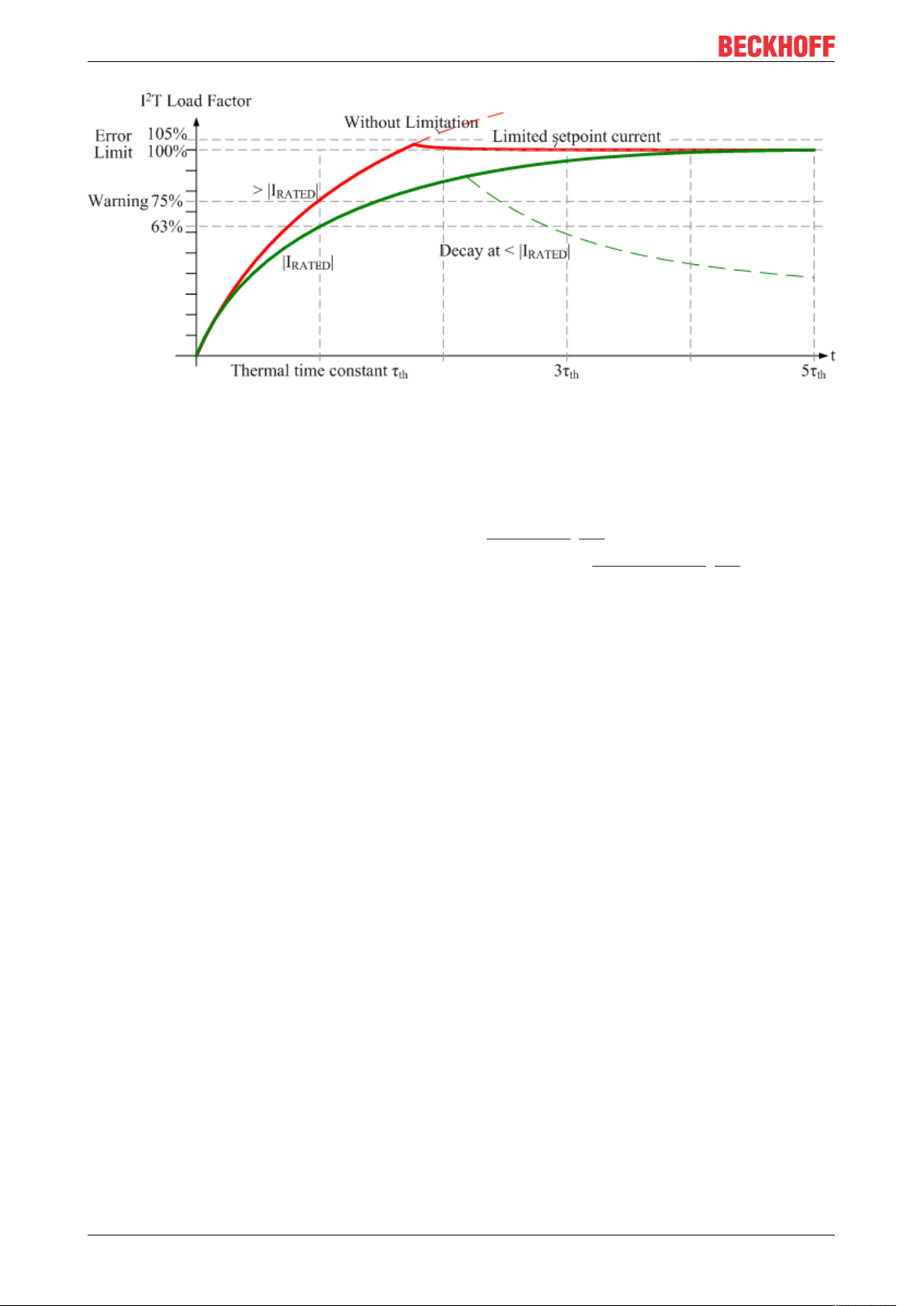
Thermal I²T motor model
The thermal I²T motor model represents the thermal behavior of the motor winding taking into account the
absolute thermal resistance Rth and the thermal capacity Cth of motor and the stator winding.
The model assumes that the motor reaches its maximum continuous operating temperature T
continuous operation with rated current I
. This temperature corresponds to 100% motor load. During
nom
nom
during
operation at rated current the motor model reaches a load of 63% after a time of τth=Rth∙Cth and slowly
reaches its continuous operating temperature.
If the motor is operated with a current that is greater than the rated current, the model reaches 100% load
more quickly.
If the load of the I²T model exceeds 100%, the requested set current is limited to the rated current, in order to
protect the motor winding thermally. The load reduces to a maximum of 100%. If the current falls below the
rated current, the load falls below 100% and the set current limitation is cancelled.
For a motor that has been cooled to ambient temperature, the time for reaching 100% load with a set current
that exceeds the rated current can be estimated with τth∙I
nom
²/I
actual
².
The actual load must be known for exact calculation of the time when the 100% load threshold is exceeded.
EL72x1-901x 23Version: 2.0
Page 24
Product overview
Fig.13: Limitation to the rated motor current
2.5 Start-up
For commissioning:
• mount the EL72x1-901x as described in the chapter Installation [}36].
• configure the EL72x1-901x in TwinCAT as described in the chapter Commissioning [}57].
EL72x1-901x24 Version: 2.0
Page 25

Basics communication
3 Basics communication
3.1 EtherCAT basics
Please refer to the EtherCAT System Documentation for the EtherCAT fieldbus basics.
3.2 EtherCAT cabling – wire-bound
The cable length between two EtherCAT devices must not exceed 100 m. This results from the FastEthernet
technology, which, above all for reasons of signal attenuation over the length of the cable, allows a maximum
link length of 5 + 90 + 5 m if cables with appropriate properties are used. See also the Design
recommendations for the infrastructure for EtherCAT/Ethernet.
Cables and connectors
For connecting EtherCAT devices only Ethernet connections (cables + plugs) that meet the requirements of
at least category 5 (CAt5) according to EN 50173 or ISO/IEC 11801 should be used. EtherCAT uses 4 wires
for signal transfer.
EtherCAT uses RJ45 plug connectors, for example. The pin assignment is compatible with the Ethernet
standard (ISO/IEC 8802-3).
Pin Color of conductor Signal Description
1 yellow TD + Transmission Data +
2 orange TD - Transmission Data 3 white RD + Receiver Data +
6 blue RD - Receiver Data -
Due to automatic cable detection (auto-crossing) symmetric (1:1) or cross-over cables can be used between
EtherCAT devices from Beckhoff.
Recommended cables
Suitable cables for the connection of EtherCAT devices can be found on the Beckhoff website!
E-Bus supply
A bus coupler can supply the EL terminals added to it with the E-bus system voltage of 5V; a coupler is
thereby loadable up to 2A as a rule (see details in respective device documentation).
Information on how much current each EL terminal requires from the E-bus supply is available online and in
the catalogue. If the added terminals require more current than the coupler can supply, then power feed
terminals (e.g. EL9410) must be inserted at appropriate places in the terminal strand.
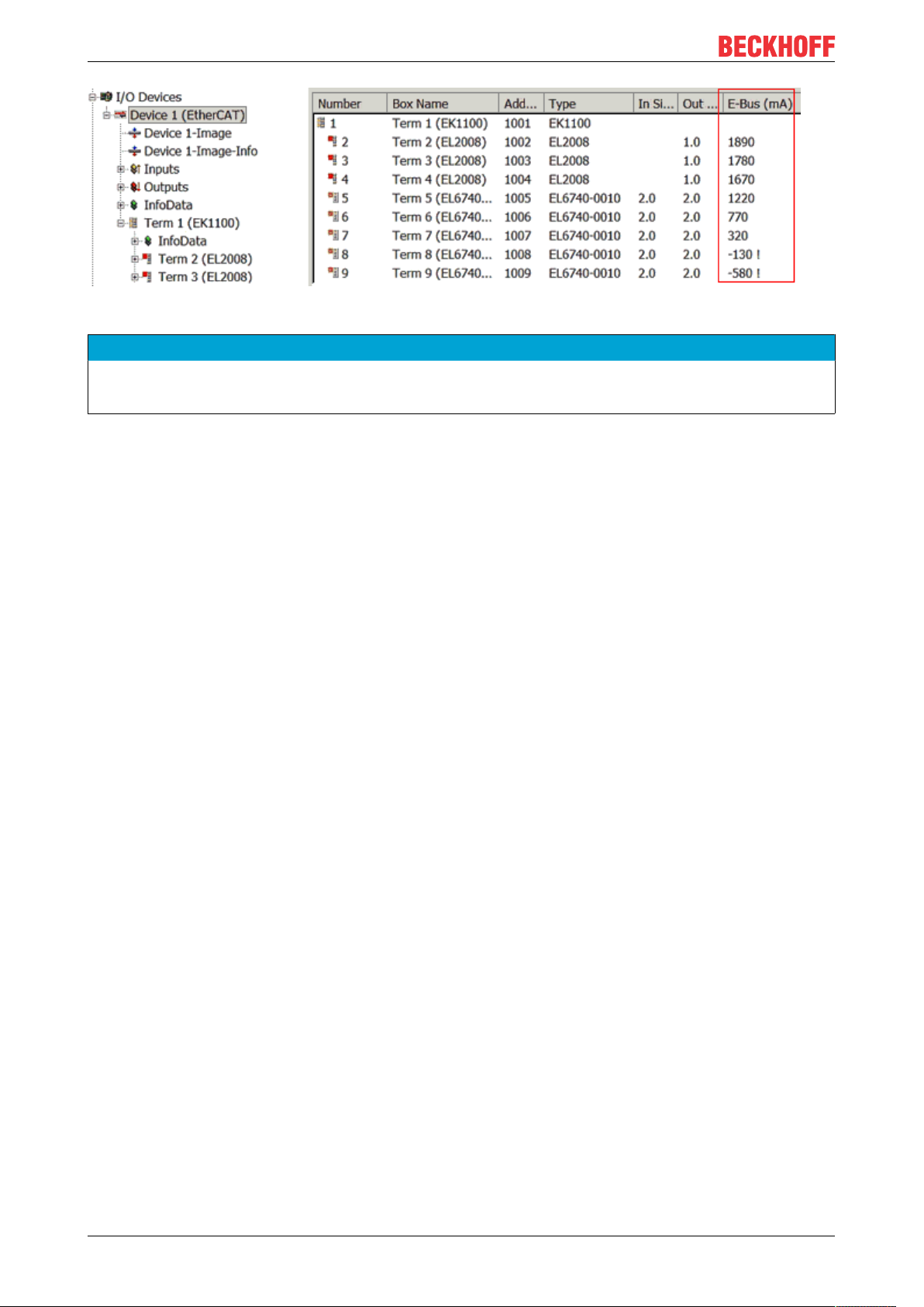
The pre-calculated theoretical maximum E-Bus current is displayed in the TwinCAT System Manager. A
shortfall is marked by a negative total amount and an exclamation mark; a power feed terminal is to be
placed before such a position.
EL72x1-901x 25Version: 2.0
Page 26
Basics communication
Fig.14: System manager current calculation
NOTE
Malfunction possible!
The same ground potential must be used for the E-Bus supply of all EtherCAT terminals in a terminal block!
3.3 General notes for setting the watchdog
ELxxxx terminals are equipped with a safety feature (watchdog) that switches off the outputs after a
specifiable time e.g. in the event of an interruption of the process data traffic, depending on the device and
settings, e.g. in OFF state.
The EtherCAT slave controller (ESC) in the EL2xxx terminals features two watchdogs:
• SM watchdog (default: 100 ms)
• PDI watchdog (default: 100 ms)
SM watchdog (SyncManager Watchdog)
The SyncManager watchdog is reset after each successful EtherCAT process data communication with the
terminal. If no EtherCAT process data communication takes place with the terminal for longer than the set
and activated SM watchdog time, e.g. in the event of a line interruption, the watchdog is triggered and the
outputs are set to FALSE. The OP state of the terminal is unaffected. The watchdog is only reset after a
successful EtherCAT process data access. Set the monitoring time as described below.
The SyncManager watchdog monitors correct and timely process data communication with the ESC from the
EtherCAT side.
PDI watchdog (Process Data Watchdog)
If no PDI communication with the EtherCAT slave controller (ESC) takes place for longer than the set and
activated PDI watchdog time, this watchdog is triggered.
PDI (Process Data Interface) is the internal interface between the ESC and local processors in the EtherCAT
slave, for example. The PDI watchdog can be used to monitor this communication for failure.
The PDI watchdog monitors correct and timely process data communication with the ESC from the
application side.
The settings of the SM- and PDI-watchdog must be done for each slave separately in the TwinCAT System
Manager.
EL72x1-901x26 Version: 2.0
Page 27
Basics communication
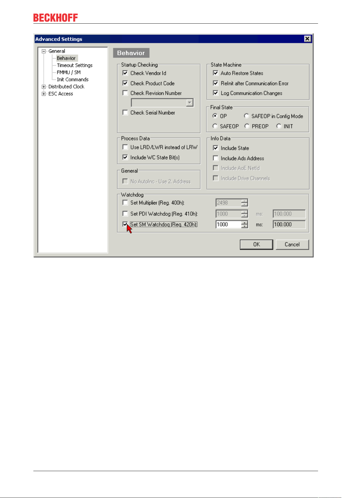
Fig.15: EtherCAT tab -> Advanced Settings -> Behavior -> Watchdog
Notes:
• the multiplier is valid for both watchdogs.
• each watchdog has its own timer setting, the outcome of this in summary with the multiplier is a
resulting time.
• Important: the multiplier/timer setting is only loaded into the slave at the start up, if the checkbox is
activated.
If the checkbox is not activated, nothing is downloaded and the ESC settings remain unchanged.
Multiplier
Multiplier
Both watchdogs receive their pulses from the local terminal cycle, divided by the watchdog multiplier:
1/25 MHz * (watchdog multiplier + 2) = 100µs (for default setting of 2498 for the multiplier)
The standard setting of 1000 for the SM watchdog corresponds to a release time of 100ms.
The value in multiplier + 2 corresponds to the number of basic 40 ns ticks representing a watchdog tick.
The multiplier can be modified in order to adjust the watchdog time over a larger range.
EL72x1-901x 27Version: 2.0
Page 28
Basics communication
Example “Set SM watchdog”
This checkbox enables manual setting of the watchdog times. If the outputs are set and the EtherCAT
communication is interrupted, the SM watchdog is triggered after the set time and the outputs are erased.
This setting can be used for adapting a terminal to a slower EtherCAT master or long cycle times. The
default SM watchdog setting is 100ms. The setting range is 0...65535. Together with a multiplier with a
range of 1...65535 this covers a watchdog period between 0...~170 seconds.
Calculation
Multiplier = 2498 → watchdog base time = 1 / 25MHz * (2498 + 2) = 0.0001seconds = 100µs
SM watchdog = 10000 → 10000 * 100µs = 1second watchdog monitoring time
CAUTION
Undefined state possible!
The function for switching off of the SM watchdog via SM watchdog = 0 is only implemented in terminals
from version -0016. In previous versions this operating mode should not be used.
CAUTION
Damage of devices and undefined state possible!
If the SM watchdog is activated and a value of 0 is entered the watchdog switches off completely. This is
the deactivation of the watchdog! Set outputs are NOT set in a safe state, if the communication is interrupted.
3.4 EtherCAT State Machine
The state of the EtherCAT slave is controlled via the EtherCAT State Machine (ESM). Depending upon the
state, different functions are accessible or executable in the EtherCAT slave. Specific commands must be
sent by the EtherCAT master to the device in each state, particularly during the bootup of the slave.
A distinction is made between the following states:
• Init
• Pre-Operational
• Safe-Operational and
• Operational
• Boot
The regular state of each EtherCAT slave after bootup is the OP state.
EL72x1-901x28 Version: 2.0
Page 29
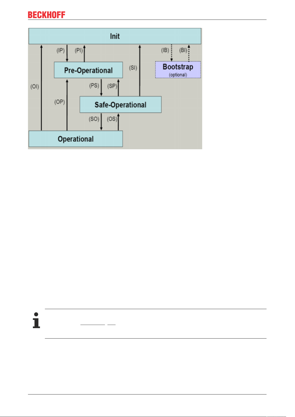
Fig.16: States of the EtherCAT State Machine
Basics communication
Init
After switch-on the EtherCAT slave in the Init state. No mailbox or process data communication is possible.
The EtherCAT master initializes sync manager channels 0 and 1 for mailbox communication.
Pre-Operational (Pre-Op)
During the transition between Init and Pre-Op the EtherCAT slave checks whether the mailbox was initialized
correctly.
In Pre-Op state mailbox communication is possible, but not process data communication. The EtherCAT
master initializes the sync manager channels for process data (from sync manager channel 2), the FMMU
channels and, if the slave supports configurable mapping, PDO mapping or the sync manager PDO
assignment. In this state the settings for the process data transfer and perhaps terminal-specific parameters
that may differ from the default settings are also transferred.
Safe-Operational (Safe-Op)
During transition between Pre-Op and Safe-Op the EtherCAT slave checks whether the sync manager
channels for process data communication and, if required, the distributed clocks settings are correct. Before
it acknowledges the change of state, the EtherCAT slave copies current input data into the associated DPRAM areas of the EtherCAT slave controller (ECSC).
In Safe-Op state mailbox and process data communication is possible, although the slave keeps its outputs
in a safe state, while the input data are updated cyclically.
Outputs in SAFEOP state
The default set watchdog [}26] monitoring sets the outputs of the module in a safe state - depending on the settings in SAFEOP and OP - e.g. in OFF state. If this is prevented by deactivation of the
watchdog monitoring in the module, the outputs can be switched or set also in the SAFEOP state.
Operational (Op)
Before the EtherCAT master switches the EtherCAT slave from Safe-Op to Op it must transfer valid output
data.
In the Op state the slave copies the output data of the masters to its outputs. Process data and mailbox
communication is possible.
EL72x1-901x 29Version: 2.0
Page 30

Basics communication
Boot
In the Boot state the slave firmware can be updated. The Boot state can only be reached via the Init state.
In the Boot state mailbox communication via the file access over EtherCAT (FoE) protocol is possible, but no
other mailbox communication and no process data communication.
3.5 CoE Interface
General description
The CoE interface (CAN application protocol over EtherCAT)) is used for parameter management of
EtherCAT devices. EtherCAT slaves or the EtherCAT master manage fixed (read only) or variable
parameters which they require for operation, diagnostics or commissioning.
CoE parameters are arranged in a table hierarchy. In principle, the user has read access via the fieldbus.
The EtherCAT master (TwinCAT System Manager) can access the local CoE lists of the slaves via
EtherCAT in read or write mode, depending on the attributes.
Different CoE parameter types are possible, including string (text), integer numbers, Boolean values or larger
byte fields. They can be used to describe a wide range of features. Examples of such parameters include
manufacturer ID, serial number, process data settings, device name, calibration values for analog
measurement or passwords.
The order is specified in two levels via hexadecimal numbering: (main)index, followed by subindex. The
value ranges are
• Index: 0x0000 …0xFFFF (0...65535
• SubIndex: 0x00…0xFF (0...255
dez
)
dez
)
A parameter localized in this way is normally written as 0x8010:07, with preceding “0x” to identify the
hexadecimal numerical range and a colon between index and subindex.
The relevant ranges for EtherCAT fieldbus users are:
• 0x1000: This is where fixed identity information for the device is stored, including name, manufacturer,
serial number etc., plus information about the current and available process data configurations.
• 0x8000: This is where the operational and functional parameters for all channels are stored, such as
filter settings or output frequency.
Other important ranges are:
• 0x4000: here are the channel parameters for some EtherCAT devices. Historically, this was the first
parameter area before the 0x8000 area was introduced. EtherCAT devices that were previously
equipped with parameters in 0x4000 and changed to 0x8000 support both ranges for compatibility
reasons and mirror internally.
• 0x6000: Input PDOs (“input” from the perspective of the EtherCAT master)
• 0x7000: Output PDOs (“output” from the perspective of the EtherCAT master)
Availability
Not every EtherCAT device must have a CoE list. Simple I/O modules without dedicated processor
usually have no variable parameters and therefore no CoE list.
If a device has a CoE list, it is shown in the TwinCAT System Manager as a separate tab with a listing of the
elements:
EL72x1-901x30 Version: 2.0
Page 31

Basics communication
Fig.17: “CoE Online” tab
The figure above shows the CoE objects available in device “EL2502”, ranging from 0x1000 to 0x1600. The
subindices for 0x1018 are expanded.
Data management and function “NoCoeStorage”
Some parameters, particularly the setting parameters of the slave, are configurable and writeable. This can
be done in write or read mode
• via the System Manager (Fig. “CoE Online” tab) by clicking
This is useful for commissioning of the system/slaves. Click on the row of the index to be
parameterized and enter a value in the “SetValue” dialog.
• from the control system/PLC via ADS, e.g. through blocks from the TcEtherCAT.lib library
This is recommended for modifications while the system is running or if no System Manager or
operating staff are available.
Data management
If slave CoE parameters are modified online, Beckhoff devices store any changes in a fail-safe
manner in the EEPROM, i.e. the modified CoE parameters are still available after a restart.
The situation may be different with other manufacturers.
An EEPROM is subject to a limited lifetime with respect to write operations. From typically 100,000
write operations onwards it can no longer be guaranteed that new (changed) data are reliably saved
or are still readable. This is irrelevant for normal commissioning. However, if CoE parameters are
continuously changed via ADS at machine runtime, it is quite possible for the lifetime limit to be
reached. Support for the NoCoeStorage function, which suppresses the saving of changed CoE values, depends on the firmware version.
Please refer to the technical data in this documentation as to whether this applies to the respective
device.
• If the function is supported: the function is activated by entering the code word 0x12345678 once
in CoE 0xF008 and remains active as long as the code word is not changed. After switching the
device on it is then inactive. Changed CoE values are not saved in the EEPROM and can thus
be changed any number of times.
• Function is not supported: continuous changing of CoE values is not permissible in view of the
lifetime limit.
EL72x1-901x 31Version: 2.0
Page 32

Basics communication
Startup list
Changes in the local CoE list of the terminal are lost if the terminal is replaced. If a terminal is replaced with a new Beckhoff terminal, it will have the default settings. It is therefore advisable to link
all changes in the CoE list of an EtherCAT slave with the Startup list of the slave, which is processed whenever the EtherCAT fieldbus is started. In this way a replacement EtherCAT slave can
automatically be parameterized with the specifications of the user.
If EtherCAT slaves are used which are unable to store local CoE values permanently, the Startup
list must be used.
Recommended approach for manual modification of CoE parameters
• Make the required change in the System Manager
The values are stored locally in the EtherCAT slave
• If the value is to be stored permanently, enter it in the Startup list.
The order of the Startup entries is usually irrelevant.
Fig.18: Startup list in the TwinCAT System Manager
The Startup list may already contain values that were configured by the System Manager based on the ESI
specifications. Additional application-specific entries can be created.
Online/offline list
While working with the TwinCAT System Manager, a distinction has to be made whether the EtherCAT
device is “available”, i.e. switched on and linked via EtherCAT and therefore online, or whether a
configuration is created offline without connected slaves.
In both cases a CoE list as shown in Fig. “CoE online tab” is displayed. The connectivity is shown as offline/
online.
• If the slave is offline
◦ The offline list from the ESI file is displayed. In this case modifications are not meaningful or
possible.
◦ The configured status is shown under Identity.
◦ No firmware or hardware version is displayed, since these are features of the physical device.
◦ Offline is shown in red.
EL72x1-901x32 Version: 2.0
Page 33

Basics communication
Fig.19: Offline list
• If the slave is online
◦ The actual current slave list is read. This may take several seconds, depending on the size and
cycle time.
◦ The actual identity is displayed
◦ The firmware and hardware version of the equipment according to the electronic information is
displayed
◦ Online is shown in green.
Fig.20: Online list
EL72x1-901x 33Version: 2.0
Page 34

Basics communication
Channel-based order
The CoE list is available in EtherCAT devices that usually feature several functionally equivalent channels.
For example, a 4-channel analog 0...10V input terminal also has four logical channels and therefore four
identical sets of parameter data for the channels. In order to avoid having to list each channel in the
documentation, the placeholder “n” tends to be used for the individual channel numbers.
In the CoE system 16 indices, each with 255 subindices, are generally sufficient for representing all channel
parameters. The channel-based order is therefore arranged in 16
dec
/10
steps. The parameter range
hex
0x8000 exemplifies this:
• Channel 0: parameter range 0x8000:00 ... 0x800F:255
• Channel 1: parameter range 0x8010:00 ... 0x801F:255
• Channel 2: parameter range 0x8020:00 ... 0x802F:255
• ...
This is generally written as 0x80n0.
Detailed information on the CoE interface can be found in the EtherCAT system documentation on the
Beckhoff website.
EL72x1-901x34 Version: 2.0
Page 35

Basics communication
3.6 Distributed Clock
The distributed clock represents a local clock in the EtherCAT slave controller (ESC) with the following
characteristics:
• Unit 1 ns
• Zero point 1.1.2000 00:00
• Size 64 bit (sufficient for the next 584 years; however, some EtherCAT slaves only offer 32-bit support,
i.e. the variable overflows after approx. 4.2 seconds)
• The EtherCAT master automatically synchronizes the local clock with the master clock in the EtherCAT
bus with a precision of < 100 ns.
For detailed information please refer to the EtherCAT system description.
EL72x1-901x 35Version: 2.0
Page 36

Installation
4 Installation
4.1 Safety instructions
Before installing and commissioning the TwinSAFE components please read the safety instructions in the
foreword of this documentation.
4.2 Environmental conditions
Please ensure that the TwinSAFE components are only transported, stored and operated under the specified
conditions (see technical data)!
WARNING
Risk of injury!
The TwinSAFE components must not be used under the following operating conditions.
• under the influence of ionizing radiation (that exceeds the level of the natural environmental radiation)
• in corrosive environments
• in an environment that leads to unacceptable soiling of the TwinSAFE component
NOTE
Electromagnetic compatibility
The TwinSAFE components comply with the current standards on electromagnetic compatibility with regard
to spurious radiation and immunity to interference in particular.
However, in cases where devices such as mobile phones, radio equipment, transmitters or high-frequency
systems that exceed the interference emissions limits specified in the standards are operated near TwinSAFE components, the function of the TwinSAFE components may be impaired.
4.3 Transport / storage
Use the original packaging in which the components were delivered for transporting and storing the
TwinSAFE components.
CAUTION
Note the specified environmental conditions
Please ensure that the digital TwinSAFE components are only transported and stored under the specified
environmental conditions (see technical data).
4.4 Control cabinet / terminal box
The TwinSAFE terminals must be installed in a control cabinet or terminal box with IP54 protection class
according to IEC60529 as a minimum.
EL72x1-901x36 Version: 2.0
Page 37

Installation
4.5 Instructions for ESD protection
NOTE
Destruction of the devices by electrostatic discharge possible!
The devices contain components at risk from electrostatic discharge caused by improper handling.
• Please ensure you are electrostatically discharged and avoid touching the contacts of the device directly.
• Avoid contact with highly insulating materials (synthetic fibers, plastic film etc.).
• Surroundings (working place, packaging and personnel) should by grounded probably, when handling
with the devices.
• Each assembly must be terminated at the right hand end with an EL9011 or EL9012 bus end cap, to ensure the protection class and ESD protection.
Fig.21: Spring contacts of the Beckhoff I/O components
4.6 Installation on mounting rails
WARNING
Risk of electric shock and damage of device!
Bring the bus terminal system into a safe, powered down state before starting installation, disassembly or
wiring of the bus terminals!
EL72x1-901x 37Version: 2.0
Page 38

Installation
Assembly
Fig.22: Attaching on mounting rail
The bus coupler and bus terminals are attached to commercially available 35mm mounting rails (DIN rails
according to EN60715) by applying slight pressure:
1. First attach the fieldbus coupler to the mounting rail.
2. The bus terminals are now attached on the right-hand side of the fieldbus coupler. Join the components with tongue and groove and push the terminals against the mounting rail, until the lock clicks
onto the mounting rail.
If the terminals are clipped onto the mounting rail first and then pushed together without tongue and
groove, the connection will not be operational! When correctly assembled, no significant gap should
be visible between the housings.
Fixing of mounting rails
The locking mechanism of the terminals and couplers extends to the profile of the mounting rail. At
the installation, the locking mechanism of the components must not come into conflict with the fixing
bolts of the mounting rail. To mount the mounting rails with a height of 7.5mm under the terminals
and couplers, you should use flat mounting connections (e.g. countersunk screws or blind rivets).
EL72x1-901x38 Version: 2.0
Page 39

Disassembly
Fig.23: Disassembling of terminal
Each terminal is secured by a lock on the mounting rail, which must be released for disassembly:
Installation
1. Pull the terminal by its orange-colored lugs approximately 1cm away from the mounting rail. In doing
so for this terminal the mounting rail lock is released automatically and you can pull the terminal out of
the bus terminal block easily without excessive force.
2. Grasp the released terminal with thumb and index finger simultaneous at the upper and lower grooved
housing surfaces and pull the terminal out of the bus terminal block.
Connections within a bus terminal block
The electric connections between the Bus Coupler and the Bus Terminals are automatically realized by
joining the components:
• The six spring contacts of the K-Bus/E-Bus deal with the transfer of the data and the supply of the Bus
Terminal electronics.
• The power contacts deal with the supply for the field electronics and thus represent a supply rail within
the bus terminal block. The power contacts are supplied via terminals on the Bus Coupler (up to 24V)
or for higher voltages via power feed terminals.
Power Contacts
During the design of a bus terminal block, the pin assignment of the individual Bus Terminals must
be taken account of, since some types (e.g. analog Bus Terminals or digital 4-channel Bus Terminals) do not or not fully loop through the power contacts. Power Feed Terminals (KL91xx, KL92xx
or EL91xx, EL92xx) interrupt the power contacts and thus represent the start of a new supply rail.
PE power contact
The power contact labeled PE can be used as a protective earth. For safety reasons this contact mates first
when plugging together, and can ground short-circuit currents of up to 125A.
EL72x1-901x 39Version: 2.0
Page 40

Installation
Fig.24: Power contact on left side
NOTE
Possible damage of the device
Note that, for reasons of electromagnetic compatibility, the PE contacts are capacitatively coupled to the
mounting rail. This may lead to incorrect results during insulation testing or to damage on the terminal (e.g.
disruptive discharge to the PE line during insulation testing of a consumer with a nominal voltage of 230V).
For insulation testing, disconnect the PE supply line at the Bus Coupler or the Power Feed Terminal! In order to decouple further feed points for testing, these Power Feed Terminals can be released and pulled at
least 10mm from the group of terminals.
WARNING
Risk of electric shock!
The PE power contact must not be used for other potentials!
4.7 Installation position for operation with or without fan
NOTE
Constraints regarding installation position and operating temperature range
When installing the terminals ensure that an adequate spacing is maintained between other components
above and below the terminal in order to guarantee adequate ventilation!
Prescribed installation position for operation without fan
The prescribed installation position requires the mounting rail to be installed horizontally and the connection
surfaces of the EL/KL terminals to face forward (see Fig. “Recommended distances of installation position for
operating without fan“).
The terminals are ventilated from below, which enables optimum cooling of the electronics through
convection.
EL72x1-901x40 Version: 2.0
Page 41

Installation
Fig.25: Recommended distances of installation position for operating without fan
Compliance with the distances shown in Fig. “Recommended distances of installation position for operating
without fan” is recommended.
For further information regarding the operation without fan refer to the Technical Data of the terminal.
Standard installation position for operation with fan
The standard installation position for operation with fan requires the mounting rail to be installed horizontally
and the connection surfaces of the EL/KL terminals to face forward (see Fig. Recommended distances for
installation position for operation with fan).
The terminals are ventilated fan supported (e.g. with fan cartridge ZB8610) from below.
EL72x1-901x 41Version: 2.0
Page 42

Installation
Fig.26: Recommended distances for installation position for operation with fan
Other installation positions
Due to the enforced effect of the fan on the ventilation of the terminals, other installation positions (see Fig.
“Other installation positions, example 1 + 2“) may be permitted where appropriate.
See corresponding notes in the Technical Data of the terminal.
Fig.27: Other installation positions, example 1
EL72x1-901x42 Version: 2.0
Page 43

Fig.28: Other installation positions, example 2
4.8 Positioning of passive Terminals
Installation
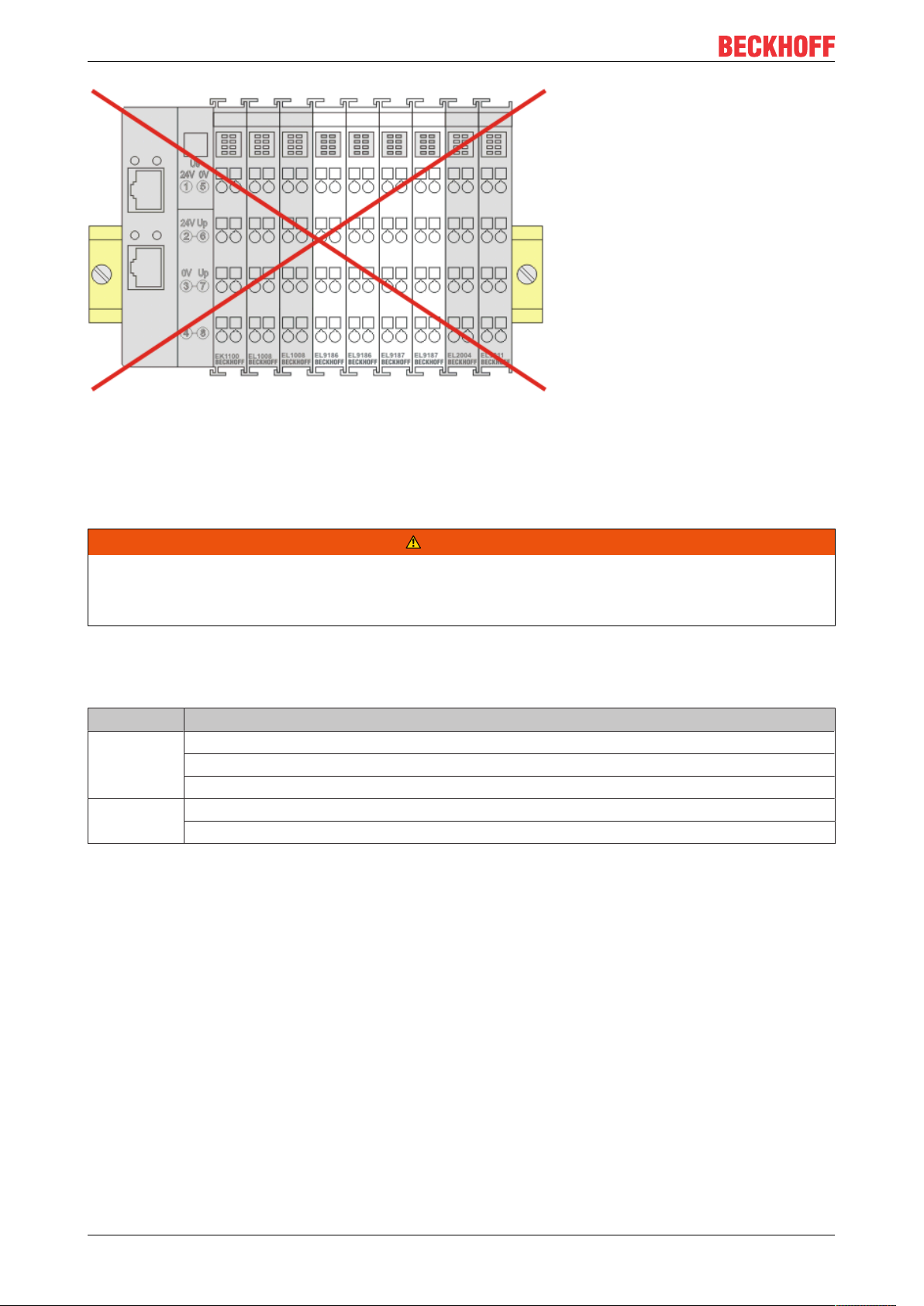
Hint for positioning of passive terminals in the bus terminal block
EtherCAT Terminals (ELxxxx / ESxxxx), which do not take an active part in data transfer within the
bus terminal block are so called passive terminals. The passive terminals have no current consumption out of the E-Bus.
To ensure an optimal data transfer, you must not directly string together more than two passive terminals!
Examples for positioning of passive terminals (highlighted)
Fig.29: Correct positioning
EL72x1-901x 43Version: 2.0
Page 44
Installation
Fig.30: Incorrect positioning
4.9 Installation instructions for enhanced mechanical load capacity
WARNING
Risk of injury through electric shock and damage to the device!
Bring the Bus Terminal system into a safe, de-energized state before starting mounting, disassembly or
wiring of the Bus Terminals!
Additional checks
The terminals have undergone the following additional tests:
Verification Explanation
Vibration 10 frequency runs in 3 axes
6 Hz < f < 60 Hz displacement 0.35 mm, constant amplitude
60.1Hz<f<500Hz acceleration 5g, constant amplitude
Shocks 1000 shocks in each direction, in 3 axes
25 g, 6 ms
Additional installation instructions
For terminals with enhanced mechanical load capacity, the following additional installation instructions apply:
• The enhanced mechanical load capacity is valid for all permissible installation positions
• Use a mounting rail according to EN 60715 TH35-15
• Fix the terminal segment on both sides of the mounting rail with a mechanical fixture, e.g. an earth
terminal or reinforced end clamp
• The maximum total extension of the terminal segment (without coupler) is:
64 terminals (12mm mounting with) or 32 terminals (24mm mounting with)
• Avoid deformation, twisting, crushing and bending of the mounting rail during edging and installation of
the rail
• The mounting points of the mounting rail must be set at 5 cm intervals
• Use countersunk head screws to fasten the mounting rail
• The free length between the strain relief and the wire connection should be kept as short as possible. A
distance of approx. 10cm should be maintained to the cable duct.
EL72x1-901x44 Version: 2.0
Page 45

Installation
4.10 Connection
4.10.1 Connection system
WARNING
Risk of electric shock and damage of device!
Bring the bus terminal system into a safe, powered down state before starting installation, disassembly or
wiring of the bus terminals!
Overview
The Bus Terminal system offers different connection options for optimum adaptation to the respective
application:
• The terminals of ELxxxx and KLxxxx series with standard wiring include electronics and connection
level in a single enclosure.
• The terminals of ESxxxx and KSxxxx series feature a pluggable connection level and enable steady
wiring while replacing.
• The High Density Terminals (HD Terminals) include electronics and connection level in a single
enclosure and have advanced packaging density.
Standard wiring (ELxxxx / KLxxxx)
Fig.31: Standard wiring
The terminals of ELxxxx and KLxxxx series have been tried and tested for years.
They feature integrated screwless spring force technology for fast and simple assembly.
Pluggable wiring (ESxxxx / KSxxxx)
Fig.32: Pluggable wiring
The terminals of ESxxxx and KSxxxx series feature a pluggable connection level.
The assembly and wiring procedure is the same as for the ELxxxx and KLxxxx series.
The pluggable connection level enables the complete wiring to be removed as a plug connector from the top
of the housing for servicing.
The lower section can be removed from the terminal block by pulling the unlocking tab.
Insert the new component and plug in the connector with the wiring. This reduces the installation time and
eliminates the risk of wires being mixed up.
The familiar dimensions of the terminal only had to be changed slightly. The new connector adds about 3
mm. The maximum height of the terminal remains unchanged.
EL72x1-901x 45Version: 2.0
Page 46

Installation
A tab for strain relief of the cable simplifies assembly in many applications and prevents tangling of individual
connection wires when the connector is removed.
Conductor cross sections between 0.08mm2 and 2.5mm2 can continue to be used with the proven spring
force technology.
The overview and nomenclature of the product names for ESxxxx and KSxxxx series has been retained as
known from ELxxxx and KLxxxx series.
High Density Terminals (HD Terminals)
Fig.33: High Density Terminals
The Bus Terminals from these series with 16 terminal points are distinguished by a particularly compact
design, as the packaging density is twice as large as that of the standard 12mm Bus Terminals. Massive
conductors and conductors with a wire end sleeve can be inserted directly into the spring loaded terminal
point without tools.
Wiring HD Terminals
The High Density Terminals of the ELx8xx and KLx8xx series doesn't support pluggable wiring.
Ultrasonically “bonded” (ultrasonically welded) conductors
Ultrasonically “bonded” conductors
It is also possible to connect the Standard and High Density Terminals with ultrasonically
“bonded” (ultrasonically welded) conductors. In this case, please note the tables concerning the
wire-size width below!
4.10.2 Wiring
WARNING
Risk of electric shock and damage of device!
Bring the bus terminal system into a safe, powered down state before starting installation, disassembly or
wiring of the Bus Terminals!
EL72x1-901x46 Version: 2.0
Page 47

Terminals for standard wiring ELxxxx/KLxxxx and for pluggable wiring ESxxxx/KSxxxx
Installation
Fig.34: Connecting a cable on a terminal point
Up to eight terminal points enable the connection of solid or finely stranded cables to the Bus Terminal. The
terminal points are implemented in spring force technology. Connect the cables as follows:
1. Open a terminal point by pushing a screwdriver straight against the stop into the square opening
above the terminal point. Do not turn the screwdriver or move it alternately (don't toggle).
2. The wire can now be inserted into the round terminal opening without any force.
3. The terminal point closes automatically when the pressure is released, holding the wire securely and
permanently.
See the following table for the suitable wire size width.
Terminal housing ELxxxx, KLxxxx ESxxxx, KSxxxx
Wire size width (single core wires) 0.08 ... 2.5mm
Wire size width (fine-wire conductors) 0.08 ... 2.5mm
Wire size width (conductors with a wire end sleeve) 0.14 ... 1.5mm
2
2
2
0.08 ... 2.5mm
0,08 ... 2.5mm
0.14 ... 1.5mm
2
2
2
Wire stripping length 8 ... 9mm 9 ... 10mm
High Density Terminals (HD Terminals [}46]) with 16 terminal points
The conductors of the HD Terminals are connected without tools for single-wire conductors using the direct
plug-in technique, i.e. after stripping the wire is simply plugged into the terminal point. The cables are
released, as usual, using the contact release with the aid of a screwdriver. See the following table for the
suitable wire size width.
Terminal housing High Density Housing
Wire size width (single core wires) 0.08 ... 1.5mm
Wire size width (fine-wire conductors) 0.25 ... 1.5mm
Wire size width (conductors with a wire end sleeve) 0.14 ... 0.75mm
Wire size width (ultrasonically “bonded" conductors) only 1.5mm
2
2
2
2
Wire stripping length 8 ... 9mm
EL72x1-901x 47Version: 2.0
Page 48

Installation
4.11 Example configuration for temperature measurement
Fig.35: Example configuration for temperature measurement
The example configuration for the temperature measurement consists of an EK1100 EtherCAT coupler with
connected terminals that match the typical distribution of digital and analog signal types at a machine. On the
EL6900 a safety project is active, which reads safe inputs and enables all 4 safe outputs during the
measurement.
External heat sources / radiant heat / impaired convection
The maximum permissible ambient temperature of 55°C was checked with the above example configuration. Impaired convection, an unfavorable location near heat sources or an unfavorable configuration of the EtherCAT Terminals may result in overheating of the terminals.
The key parameter is always the maximum permitted internally measured temperature of 95°C,
above which the TwinSAFE terminals switch to safe state and report an error. The internal temperature can be read from the TwinSAFE components via CoE (see chapter Diagnose).
4.12 Shielding concept
Together with the shield busbar, the prefabricated cables from Beckhoff Automation offer optimum protection
against electromagnetic interference.
It is highly recommended to apply the shield as close as possible to the terminal, in order to minimize
operational disturbances.
Connection of the motor cable to the shield busbar
Fasten the shield busbar supports 1 to the DIN rail 2. The mounting rail 2 must be in contact with the metallic
rear wall of the control cabinet over a wide area. Install the shield busbar 3 as shown below.
As an alternative, a shield busbar clamp 3a can be screwed directly to the metallic rear wall of the control
cabinet (fig. “shield busbar clamp”)
EL72x1-901x48 Version: 2.0
Page 49

Installation
Fig.36: Shield busbar
Fig.37: Shield busbar clamp
EL72x1-901x 49Version: 2.0
Page 50

Installation
Connect the cores 4 of the motor cable 5, then attach the copper-sheathed end 6 of the motor cable 5 with
the shield clamp 7 to the shield busbar 3 or shield busbar clamp 3a. Tighten the screw 8 to the stop.
Fasten the PE clamp 9 to the shield busbar 3 or shield busbar clamp 3a. Clamp the PE core 10 of the motor
cable 5 under the PE clamp 9.
Fig.38: Shield connection
Connection of the feedback cable to the motor
Twisting of the feedback cable cores
The feedback cable cores should be twisted, in order to avoid operational disturbances.
When screwing the feedback plug to the motor, the shield of the feedback cable is connected via the metallic
plug fastener.
On the terminal side the shield can also be connected. Connect the cores of the feedback cable and attach
the copper-sheathed end of the feedback cable to the shield busbar 3 or shield busbar clamp 3a with the
shield clamp 7. The motor cable and the feedback cable can be connected to the shield clamp 7 with the
screw 8.
4.13 UL notice - Compact Motion
Application
Beckhoff EtherCAT modules are intended for use with Beckhoff’s UL Listed EtherCAT System only.
Examination
For cULus examination, the Beckhoff I/O System has only been investigated for risk of fire
and electrical shock (in accordance with UL508 and CSAC22.2 No.142).
For devices with Ethernet connectors
Not for connection to telecommunication circuits.
EL72x1-901x50 Version: 2.0
Page 51

Notes on motion devices
• Motor overtemperature
Motor overtemperature sensing is not provided by the drive.
• Application for compact motion devices
The modules are intended for use only within Beckhoff’s Programmable Controller system Listed in File E172151.
• Galvanic isolation from the supply
The modules are intended for operation within circuits not connected directly to the supply mains (galvanically isolated from the supply, i.e. on transformer secondary).
• Requirement for environmental conditions
For use in Pollution Degree 2 Environment only.
Basic principles
UL certification according to UL508. Devices with this kind of certification are marked by this sign:
Installation
Application
If terminals certified with restrictions are used, then the current consumption at 24VDC must be limited
accordingly by means of supply
• from an isolated source protected by a fuse of max. 4A (according to UL248) or
• from a voltage supply complying with NECclass2.
A voltage source complying with NECclass2 may not be connected in series or parallel with another
NECclass2compliant voltage supply!
These requirements apply to the supply of all EtherCAT bus couplers, power adaptor terminals, Bus
Terminals and their power contacts.
4.14 Notes on current measurements using Hall sensors
The device described in this documentation features one or several integrated Hall sensor for the purpose of
current measurements.
During this process, the Hall sensor monitors the magnetic field generated by a current flowing through a
conductor.
In order to prevent compromising the measurement we recommend screening exterior magnetic fields from
the device, or to keep such fields at an adequate distance.
EL72x1-901x 51Version: 2.0
Page 52

Installation
Fig.39: Note
Background
A current-carrying conductor generates a magnetic field around it according to
B = µ0 * I / (2π * d)
with
B [Tesla] magnetic field
µ0 = 4*π*10-7 [H/m] (assumption: no magnetic shielding)
I [A] current
d [m] distance to conductor
Interference from external magnetic fields
The magnetic field strength should not exceed a permitted level all around the device.
In practice this equates to a recommended minimum distance between a conductor and the device
surface as follows:
- Current 10 A: 12mm
- Current 20 A: 25mm
- Current 40 A: 50 mm
Unless specified otherwise in the device documentation, stringing together modules (e.g. terminal
blocks based on a 12 mm grid) of same type (e.g. EL2212-0000) is permitted.
EL72x1-901x52 Version: 2.0
Page 53

4.15 EL72x1-9014 - LEDs and connection
EL7201-901x
Fig.40: EL7201-901x - LEDs
LEDs
Installation
LED Color Meaning
RUN green This LED indicates the terminal's operating state:
off State of the EtherCAT State Machine: INIT=initialization of the terminal
flashing
rapidly
flashing State of the EtherCAT State Machine: PREOP = function for mailbox communication and
Single flash State of the EtherCAT State Machine: SAFEOP = verification of the Sync Manager chan-
on State of the EtherCAT State Machine: OP = normal operating state; mailbox and process
Drive OK green on Driver stage ready for operation
Limit orange on
Read OCT green flashing The electronic type plate is being read
off The reading of the electronic type plate has been completed
Warning orange flashing Error while reading the type plate
on
Enable green on
Error red on
+24 V via power
contacts
DC link supply green on Voltage for the DC link supply is present.
green on 24 V voltage supply for the terminal is present.
State of the EtherCAT State Machine: BOOTSTRAP=function for terminal firmware up-
dates [}245]
different standard-settings set
nels and the distributed clocks.
Outputs remain in safe state
data communication is possible
The LED is linked with bit 11 of the status word (MDP742 [}197] / DS402 [}219]) (internal
limit active)
Limit reached (e.g. torque or speed limit)
The LED is linked with bit 7 of the status word (MDP742 [}197] / DS402 [}219]) (warning)
The “Warning” threshold value is exceeded.
I²T model
Voltage missing at STO input
Temperature (80°C) exceeded
Voltage
The LED is linked with the bits 1 and 2 of status word (MDP742 [}197] / DS402 [}219]) (if
"Switched on" or "Operation enabled")
Driver stage enabled
The LED is linked with bit 3 of the status word (MDP742 [}197] / DS402 [}219]) (fault)
The “Error” threshold value is exceeded.
Overcurrent
STO triggered with active axis
Voltage not available
Resolver not connected
Max. temperature (100°C) exceeded
EL72x1-901x 53Version: 2.0
Page 54

Installation
Connection
Fig.41: EL7201-901x Connection
Terminal point Name Comment
1 OCT + Positive input of the absolute feedback
2 Input 1 Digital input 1
3 +24 V Power contact +24 V
4 U Motor phase U
5 W Motor phase W
6 Brake + Motor brake +
7 48 V DC link supply + (8...48 V)
8
9 OCT - Negative input of the absolute feedback
10 Input 2 Digital input 2
11 0 V Power contact 0 V
12 V Motor phase V
13 STO input Input for STO signal (24 V)
14 Brake GND Motor brake 0V
15 0 V DC link 0V supply
16
EL72x1-901x54 Version: 2.0
Page 55

EL7211-901x, EL7221-901x
Fig.42: EL7211-901x, EL7221-901x - LEDs
LEDs
LED Color Meaning
RUN green This LED indicates the terminal's operating state:
off State of the EtherCAT State Machine: INIT=initialization of the terminal
flashing
rapidly
flashing State of the EtherCAT State Machine: PREOP = function for mailbox communication and
Single flash State of the EtherCAT State Machine: SAFEOP = verification of the Sync Manager chan-
on State of the EtherCAT State Machine: OP = normal operating state; mailbox and process
Drive OK green on Driver stage ready for operation
Limit orange on
Read OCT green flashing The electronic type plate is being read
off The reading of the electronic type plate has been completed
Warning orange flashing Error while reading the type plate
on
Enable green on
Error red on
+24 V via power
contacts
DC link supply green on Voltage for the DC link supply is present.
green on 24 V voltage supply for the terminal is present.
State of the EtherCAT State Machine: BOOTSTRAP=function for terminal firmware up-
dates [}245]
different standard-settings set
nels and the distributed clocks.
Outputs remain in safe state
data communication is possible
The LED is linked with bit 11 of the status word (MDP742 [}197] / DS402 [}219]) (internal
limit active)
Limit reached (e.g. torque or speed limit)
The LED is linked with bit 7 of the status word (MDP742 [}197] / DS402 [}219]) (warning)
The “Warning” threshold value is exceeded.
I²T model
Voltage missing at STO input
Temperature (80°C) exceeded
Voltage
The LED is linked with the bits 1 and 2 of status word (MDP742 [}197] / DS402 [}219]) (if
"Switched on" or "Operation enabled")
Driver stage enabled
The LED is linked with bit 3 of the status word (MDP742 [}197] / DS402 [}219]) (fault)
The “Error” threshold value is exceeded.
Overcurrent
STO triggered with active axis
Voltage not available
Resolver not connected
Max. temperature (100°C) exceeded
Installation
EL72x1-901x 55Version: 2.0
Page 56

Installation
Connection
Fig.43: EL7211-901x, EL7221-901x - Connection
Terminal point Name Comment
1 OCT + Positive input of the absolute feedback
2 Input 1 Digital input 1
3 +24 V Power contact +24 V
4 U Motor phase U
5 W Motor phase W
6 Brake + Motor brake +
7 48 V DC link supply + (8...48 V)
8
9 OCT - Negative input of the absolute feedback
10 Input 2 Digital input 2
11 0 V Power contact 0 V
12 V Motor phase V
13 STO input Input for STO signal (24 V)
14 Brake GND Motor brake 0V
15 0 V DC link 0V supply
16
1' - 16' n.c.
EL72x1-901x56 Version: 2.0
Page 57

Commissioning
5 Commissioning
5.1 TwinCAT Quick Start
TwinCAT is a development environment for real-time control including multi-PLC system, NC axis control,
programming and operation. The whole system is mapped through this environment and enables access to a
programming environment (including compilation) for the controller. Individual digital or analog inputs or
outputs can also be read or written directly, in order to verify their functionality, for example.
For further information please refer to http://infosys.beckhoff.com:
• EtherCAT Systemmanual:
Fieldbus Components → EtherCAT Terminals → EtherCAT System Documentation → Setup in the
TwinCAT System Manager
• TwinCAT2 → TwinCAT System Manager → I/O - Configuration
• In particular, TwinCAT driver installation:
Fieldbus components → Fieldbus Cards and Switches → FC900x – PCI Cards for Ethernet →
Installation
Devices contain the terminals for the actual configuration. All configuration data can be entered directly via
editor functions (offline) or via the “Scan” function (online):
• “offline”: The configuration can be customized by adding and positioning individual components.
These can be selected from a directory and configured.
◦ The procedure for offline mode can be found under http://infosys.beckhoff.com:
TwinCAT2 → TwinCAT System Manager → IO - Configuration → Adding an I/O Device
• “online”: The existing hardware configuration is read
◦ See also http://infosys.beckhoff.com:
Fieldbus components → Fieldbus cards and switches → FC900x – PCI Cards for Ethernet →
Installation → Searching for devices
The following relationship is envisaged from user PC to the individual control elements:
EL72x1-901x 57Version: 2.0
Page 58

Commissioning
Fig.44: Relationship between user side (commissioning) and installation
The user inserting of certain components (I/O device, terminal, box...) is the same in TwinCAT2 and
TwinCAT3. The descriptions below relate to the online procedure.
Sample configuration (actual configuration)
Based on the following sample configuration, the subsequent subsections describe the procedure for
TwinCAT2 and TwinCAT3:
• Control system (PLC) CX2040 including CX2100-0004 power supply unit
• Connected to the CX2040 on the right (E-bus):
EL1004 (4-channel digital input terminal 24VDC)
• Linked via the X001 port (RJ-45): EK1100 EtherCAT Coupler
• Connected to the EK1100 EtherCAT coupler on the right (E-bus):
EL2008 (8-channel digital output terminal 24VDC;0.5A)
• (Optional via X000: a link to an external PC for the user interface)
EL72x1-901x58 Version: 2.0
Page 59

Commissioning
Fig.45: Control configuration with Embedded PC, input (EL1004) and output (EL2008)
Note that all combinations of a configuration are possible; for example, the EL1004 terminal could also be
connected after the coupler, or the EL2008 terminal could additionally be connected to the CX2040 on the
right, in which case the EK1100 coupler wouldn’t be necessary.
EL72x1-901x 59Version: 2.0
Page 60

Commissioning
5.1.1 TwinCAT2
Startup
TwinCAT basically uses two user interfaces: the TwinCAT System Manager for communication with the
electromechanical components and TwinCAT PLC Control for the development and compilation of a
controller. The starting point is the TwinCAT System Manager.
After successful installation of the TwinCAT system on the PC to be used for development, the TwinCAT2
System Manager displays the following user interface after startup:
Fig.46: Initial TwinCAT2 user interface
Generally, TwinCAT can be used in local or remote mode. Once the TwinCAT system including the user
interface (standard) is installed on the respective PLC, TwinCAT can be used in local mode and thereby the
next step is “Insert Device [}62]”.
If the intention is to address the TwinCAT runtime environment installed on a PLC as development
environment remotely from another system, the target system must be made known first. In the menu under
“Actions” → “Choose Target System...”, via the symbol “ ” or the “F8” key, open the following window:
EL72x1-901x60 Version: 2.0
Page 61

Fig.47: Selection of the target system
Use “Search (Ethernet)...” to enter the target system. Thus a next dialog opens to either:
Commissioning
• enter the known computer name after “Enter Host Name / IP:” (as shown in red)
• perform a “Broadcast Search” (if the exact computer name is not known)
• enter the known computer IP or AmsNetID.
Fig.48: Specify the PLC for access by the TwinCAT System Manager: selection of the target system
Once the target system has been entered, it is available for selection as follows (a password may have to be
entered):
After confirmation with “OK” the target system can be accessed via the System Manager.
EL72x1-901x 61Version: 2.0
Page 62

Commissioning
Adding devices
In the configuration tree of the TwinCAT2 System Manager user interface on the left, select “I/ODevices”
and then right-click to open a context menu and select “ScanDevices…”, or start the action in the menu bar
via . The TwinCAT System Manager may first have to be set to “Configmode” via or via menu
“Actions” → “Set/Reset TwinCAT to Config Mode…” (Shift + F4).
Fig.49: Select “Scan Devices...”
Confirm the warning message, which follows, and select “EtherCAT” in the dialog:
Fig.50: Automatic detection of I/O devices: selection the devices to be integrated
Confirm the message “Find new boxes”, in order to determine the terminals connected to the devices. “Free
Run” enables manipulation of input and output values in “Config mode” and should also be acknowledged.
Based on the sample configuration [}58] described at the beginning of this section, the result is as follows:
EL72x1-901x62 Version: 2.0
Page 63

Commissioning
Fig.51: Mapping of the configuration in the TwinCAT2 System Manager
The whole process consists of two stages, which may be performed separately (first determine the devices,
then determine the connected elements such as boxes, terminals, etc.). A scan can also be initiated by
selecting “Device ...” from the context menu, which then reads the elements present in the configuration
below:
Fig.52: Reading of individual terminals connected to a device
This functionality is useful if the actual configuration is modified at short notice.
Programming and integrating the PLC
TwinCAT PLC Control is the development environment for the creation of the controller in different program
environments: TwinCAT PLC Control supports all languages described in IEC 61131-3. There are two textbased languages and three graphical languages.
• Text-based languages
◦ Instruction List (IL)
EL72x1-901x 63Version: 2.0
Page 64

Commissioning
◦ Structured Text (ST)
• Graphical languages
◦ Function Block Diagram (FBD)
◦ Ladder Diagram (LD)
◦ The Continuous Function Chart Editor (CFC)
◦ Sequential Function Chart (SFC)
The following section refers to Structured Text (ST).
After starting TwinCAT PLC Control, the following user interface is shown for an initial project:
Fig.53: TwinCAT PLC Control after startup
Sample variables and a sample program have been created and stored under the name “PLC_example.pro”:
EL72x1-901x64 Version: 2.0
Page 65

Commissioning
Fig.54: Sample program with variables after a compile process (without variable integration)
Warning 1990 (missing “VAR_CONFIG”) after a compile process indicates that the variables defined as
external (with the ID “AT%I*” or “AT%Q*”) have not been assigned. After successful compilation, TwinCAT
PLC Control creates a “*.tpy” file in the directory in which the project was stored. This file (“*.tpy”) contains
variable assignments and is not known to the System Manager, hence the warning. Once the System
Manager has been notified, the warning no longer appears.
First, integrate the TwinCAT PLC Control project in the System Manager via the context menu of the PLC
configuration; right-click and select “Append PLC Project…”:
Fig.55: Appending the TwinCAT PLC Control project
EL72x1-901x 65Version: 2.0
Page 66

Commissioning
Select the PLC configuration “PLC_example.tpy” in the browser window that opens. The project including the
two variables identified with “AT” are then integrated in the configuration tree of the System Manager:
Fig.56: PLC project integrated in the PLC configuration of the System Manager
The two variables “bEL1004_Ch4” and “nEL2008_value” can now be assigned to certain process objects of
the I/O configuration.
Assigning variables
Open a window for selecting a suitable process object (PDO) via the context menu of a variable of the
integrated project “PLC_example” and via “Modify Link...” “Standard”:
Fig.57: Creating the links between PLC variables and process objects
In the window that opens, the process object for the variable “bEL1004_Ch4” of type BOOL can be selected
from the PLC configuration tree:
EL72x1-901x66 Version: 2.0
Page 67

Commissioning
Fig.58: Selecting PDO of type BOOL
According to the default setting, certain PDO objects are now available for selection. In this sample the input
of channel 4 of the EL1004 terminal is selected for linking. In contrast, the checkbox “All types” must be
ticked for creating the link for the output variables, in order to allocate a set of eight separate output bits to a
byte variable. The following diagram shows the whole process:
Fig.59: Selecting several PDOs simultaneously: activate “Continuous” and “All types”
Note that the “Continuous” checkbox was also activated. This is designed to allocate the bits contained in the
byte of the variable “nEL2008_value” sequentially to all eight selected output bits of the EL2008 terminal. In
this way it is possible to subsequently address all eight outputs of the terminal in the program with a byte
corresponding to bit 0 for channel 1 to bit 7 for channel 8 of the PLC. A special symbol ( ) at the yellow or
red object of the variable indicates that a link exists. The links can also be checked by selecting a “Goto Link
Variable” from the context menu of a variable. The object opposite, in this case the PDO, is automatically
selected:
EL72x1-901x 67Version: 2.0
Page 68

Commissioning
Fig.60: Application of a “Goto Link” variable, using “MAIN.bEL1004_Ch4” as a sample
The process of assigning variables to the PDO is completed via the menu selection “Actions” → “Generate
Mappings”, key Ctrl+M or by clicking on the symbol in the menu.
This can be visualized in the configuration:
The process of creating links can also take place in the opposite direction, i.e. starting with individual PDOs
to variable. However, in this example it would then not be possible to select all output bits for the EL2008,
since the terminal only makes individual digital outputs available. If a terminal has a byte, word, integer or
similar PDO, it is possible to allocate this a set of bit-standardized variables (type “BOOL”). Here, too, a
“Goto Link Variable” from the context menu of a PDO can be executed in the other direction, so that the
respective PLC instance can then be selected.
Activation of the configuration
The allocation of PDO to PLC variables has now established the connection from the controller to the inputs
and outputs of the terminals. The configuration can now be activated. First, the configuration can be verified
via (or via “Actions” → “Check Configuration”). If no error is present, the configuration can be
activated via (or via “Actions” → “Activate Configuration…”) to transfer the System Manager settings
to the runtime system. Confirm the messages “Old configurations are overwritten!” and “Restart TwinCAT
system in Run mode” with “OK”.
A few seconds later the real-time status is displayed at the bottom right in the System Manager.
The PLC system can then be started as described below.
Starting the controller
Starting from a remote system, the PLC control has to be linked with the Embedded PC over Ethernet via
“Online” → “Choose Run-Time System…”:
EL72x1-901x68 Version: 2.0
Page 69

Commissioning
Fig.61: Choose target system (remote)
In this sample “Runtime system 1 (port 801)” is selected and confirmed. Link the PLC with the real-time
system via menu option “Online” → “Login”, the F11 key or by clicking on the symbol .The control
program can then be loaded for execution. This results in the message “No program on the controller!
Should the new program be loaded?”, which should be acknowledged with “Yes”. The runtime environment
is ready for the program start:
EL72x1-901x 69Version: 2.0
Page 70
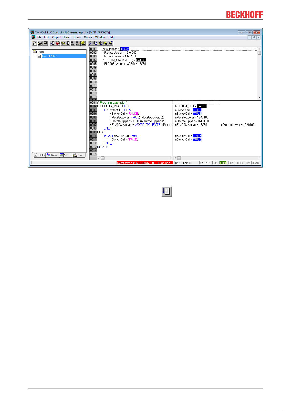
Commissioning
Fig.62: PLC Control logged in, ready for program startup
The PLC can now be started via “Online” → “Run”, F5 key or .
5.1.2 TwinCAT 3
Startup
TwinCAT makes the development environment areas available together with Microsoft Visual Studio: after
startup, the project folder explorer appears on the left in the general window area (cf. “TwinCAT System
Manager” of TwinCAT2) for communication with the electromechanical components.
After successful installation of the TwinCAT system on the PC to be used for development, TwinCAT3
(shell) displays the following user interface after startup:
EL72x1-901x70 Version: 2.0
Page 71
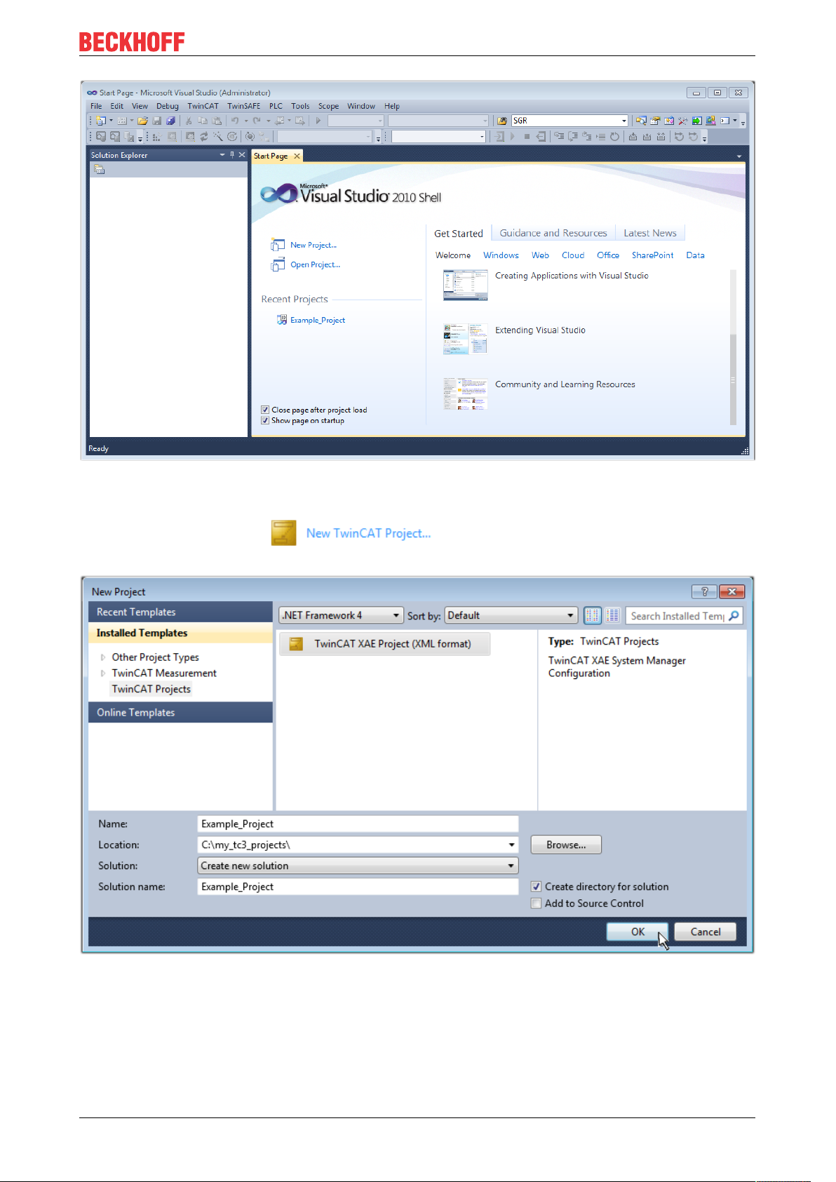
Commissioning
Fig.63: Initial TwinCAT3 user interface
First create a new project via (or under “File”→“New”→ “Project…”). In the
following dialog make the corresponding entries as required (as shown in the diagram):
Fig.64: Create new TwinCAT project
The new project is then available in the project folder explorer:
EL72x1-901x 71Version: 2.0
Page 72

Commissioning
Fig.65: New TwinCAT3 project in the project folder explorer
Generally, TwinCAT can be used in local or remote mode. Once the TwinCAT system including the user
interface (standard) is installed on the respective PLC, TwinCAT can be used in local mode and thereby the
next step is “Insert Device [}73]”.
If the intention is to address the TwinCAT runtime environment installed on a PLC as development
environment remotely from another system, the target system must be made known first. Via the symbol in
the menu bar:
expand the pull-down menu:
and open the following window:
Fig.66: Selection dialog: Choose the target system
EL72x1-901x72 Version: 2.0
Page 73

Use “Search (Ethernet)...” to enter the target system. Thus a next dialog opens to either:
• enter the known computer name after “Enter Host Name / IP:” (as shown in red)
• perform a “Broadcast Search” (if the exact computer name is not known)
• enter the known computer IP or AmsNetID.
Commissioning
Fig.67: Specify the PLC for access by the TwinCAT System Manager: selection of the target system
Once the target system has been entered, it is available for selection as follows (a password may have to be
entered):
After confirmation with “OK” the target system can be accessed via the Visual Studio shell.
Adding devices
In the project folder explorer of the Visual Studio shell user interface on the left, select “Devices” within
element “I/O”, then right-click to open a context menu and select “Scan” or start the action via in the
menu bar. The TwinCAT System Manager may first have to be set to “Config mode” via or via the
menu “TwinCAT” → “Restart TwinCAT (Config mode)”.
Fig.68: Select “Scan”
Confirm the warning message, which follows, and select “EtherCAT” in the dialog:
EL72x1-901x 73Version: 2.0
Page 74

Commissioning
Fig.69: Automatic detection of I/O devices: selection the devices to be integrated
Confirm the message “Find new boxes”, in order to determine the terminals connected to the devices. “Free
Run” enables manipulation of input and output values in “Config mode” and should also be acknowledged.
Based on the sample configuration [}58] described at the beginning of this section, the result is as follows:
Fig.70: Mapping of the configuration in VS shell of the TwinCAT3 environment
The whole process consists of two stages, which may be performed separately (first determine the devices,
then determine the connected elements such as boxes, terminals, etc.). A scan can also be initiated by
selecting “Device ...” from the context menu, which then reads the elements present in the configuration
below:
EL72x1-901x74 Version: 2.0
Page 75

Commissioning
Fig.71: Reading of individual terminals connected to a device
This functionality is useful if the actual configuration is modified at short notice.
Programming the PLC
TwinCAT PLC Control is the development environment for the creation of the controller in different program
environments: TwinCAT PLC Control supports all languages described in IEC 61131-3. There are two textbased languages and three graphical languages.
• Text-based languages
◦ Instruction List (IL)
◦ Structured Text (ST)
• Graphical languages
◦ Function Block Diagram (FBD)
◦ Ladder Diagram (LD)
◦ The Continuous Function Chart Editor (CFC)
◦ Sequential Function Chart (SFC)
The following section refers to Structured Text (ST).
In order to create a programming environment, a PLC subproject is added to the project sample via the
context menu of “PLC” in the project folder explorer by selecting “Add New Item….”:
EL72x1-901x 75Version: 2.0
Page 76

Commissioning
Fig.72: Adding the programming environment in “PLC”
In the dialog that opens select “Standard PLC project” and enter “PLC_example” as project name, for
example, and select a corresponding directory:
Fig.73: Specifying the name and directory for the PLC programming environment
The “Main” program, which already exists by selecting “Standard PLC project”, can be opened by doubleclicking on “PLC_example_project” in “POUs”. The following user interface is shown for an initial project:
EL72x1-901x76 Version: 2.0
Page 77

Commissioning
Fig.74: Initial “Main” program of the standard PLC project
To continue, sample variables and a sample program have now been created:
EL72x1-901x 77Version: 2.0
Page 78
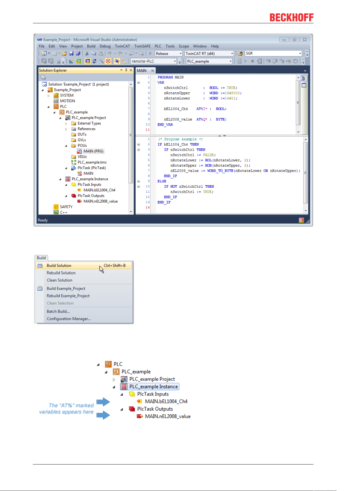
Commissioning
Fig.75: Sample program with variables after a compile process (without variable integration)
The control program is now created as a project folder, followed by the compile process:
Fig.76: Start program compilation
The following variables, identified in the ST/ PLC program with “AT%”, are then available in under
“Assignments” in the project folder explorer:
Assigning variables
Via the menu of an instance - variables in the “PLC” context, use the “Modify Link…” option to open a
window for selecting a suitable process object (PDO) for linking:
EL72x1-901x78 Version: 2.0
Page 79

Commissioning
Fig.77: Creating the links between PLC variables and process objects
In the window that opens, the process object for the variable “bEL1004_Ch4” of type BOOL can be selected
from the PLC configuration tree:
Fig.78: Selecting PDO of type BOOL
According to the default setting, certain PDO objects are now available for selection. In this sample the input
of channel 4 of the EL1004 terminal is selected for linking. In contrast, the checkbox “All types” must be
ticked for creating the link for the output variables, in order to allocate a set of eight separate output bits to a
byte variable. The following diagram shows the whole process:
EL72x1-901x 79Version: 2.0
Page 80

Commissioning
Fig.79: Selecting several PDOs simultaneously: activate “Continuous” and “All types”
Note that the “Continuous” checkbox was also activated. This is designed to allocate the bits contained in the
byte of the variable “nEL2008_value” sequentially to all eight selected output bits of the EL2008 terminal. In
this way it is possible to subsequently address all eight outputs of the terminal in the program with a byte
corresponding to bit 0 for channel 1 to bit 7 for channel 8 of the PLC. A special symbol ( ) at the yellow or
red object of the variable indicates that a link exists. The links can also be checked by selecting a “Goto Link
Variable” from the context menu of a variable. The object opposite, in this case the PDO, is automatically
selected:
Fig.80: Application of a “Goto Link” variable, using “MAIN.bEL1004_Ch4” as a sample
The process of creating links can also take place in the opposite direction, i.e. starting with individual PDOs
to variable. However, in this example it would then not be possible to select all output bits for the EL2008,
since the terminal only makes individual digital outputs available. If a terminal has a byte, word, integer or
EL72x1-901x80 Version: 2.0
Page 81
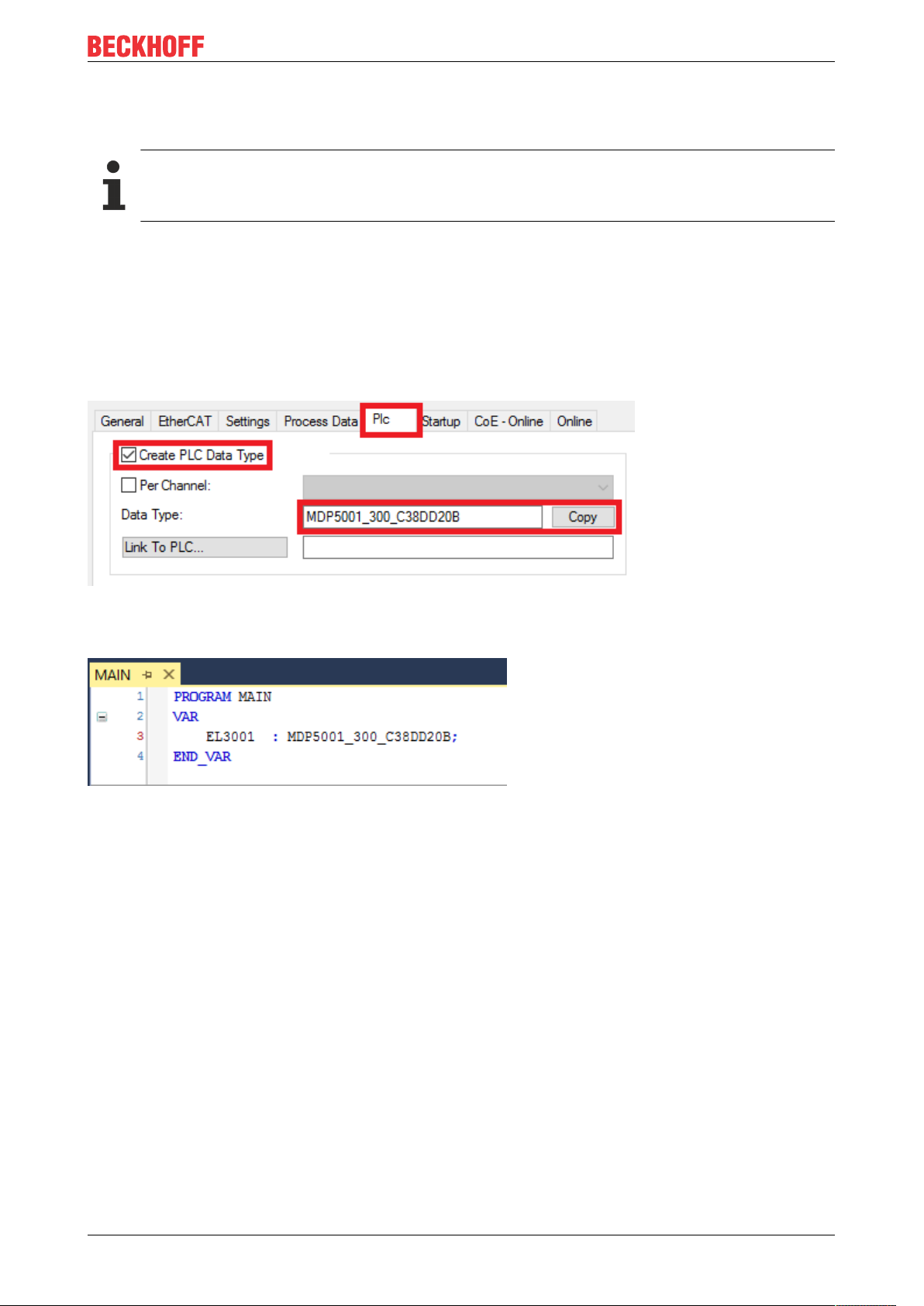
Commissioning
similar PDO, it is possible to allocate this a set of bit-standardized variables (type “BOOL”). Here, too, a
“Goto Link Variable” from the context menu of a PDO can be executed in the other direction, so that the
respective PLC instance can then be selected.
Note on the type of variable assignment
The following type of variable assignment can only be used from TwinCAT version V3.1.4024.4 onwards and is only available for terminals with a microcontroller.
In TwinCAT it is possible to create a structure from the mapped process data of a terminal. An instance of
this structure can then be created in the PLC, so it is possible to access the process data directly from the
PLC without having to declare own variables.
The procedure for the EL3001 1-channel analog input terminal -10...+10V is shown as an example.
1. First the required process data must be selected in the “Process data” tab in TwinCAT.
2. After that, the PLC data type must be generated in the tab “PLC” via the check box.
3. The data type in the “Data Type” field can then be copied using the “Copy” button.
Fig.81: Creating a PLC data type
4. An instance of the data structure of the copied data type must then be created in the PLC.
Fig.82: Instance_of_struct
5. Then the project folder must be created. This can be done either via the key combination “CTRL +
Shift + B” or via the “Build” tab in TwinCAT.
6. The structure in the “PLC” tab of the terminal must then be linked to the created instance.
EL72x1-901x 81Version: 2.0
Page 82

Commissioning
Fig.83: Linking the structure
7. In the PLC the process data can then be read or written via the structure in the program code.
Fig.84: Reading a variable from the structure of the process data
Activation of the configuration
The allocation of PDO to PLC variables has now established the connection from the controller to the inputs
and outputs of the terminals. The configuration can now be activated with or via the menu under
“TwinCAT” in order to transfer settings of the development environment to the runtime system. Confirm the
messages “Old configurations are overwritten!” and “Restart TwinCAT system in Run mode” with “OK”. The
corresponding assignments can be seen in the project folder explorer:
A few seconds later the corresponding status of the Run mode is displayed in the form of a rotating symbol
at the bottom right of the VS shell development environment. The PLC system can then be started as
described below.
EL72x1-901x82 Version: 2.0
Page 83

Commissioning
Starting the controller
Select the menu option “PLC” → “Login” or click on to link the PLC with the real-time system and load
the control program for execution. This results in the message No program on the controller! Should the new
program be loaded?, which should be acknowledged with “Yes”. The runtime environment is ready for
program start by click on symbol , the “F5” key or via “PLC” in the menu selecting “Start”. The started
programming environment shows the runtime values of individual variables:
Fig.85: TwinCAT development environment (VS shell): logged-in, after program startup
The two operator control elements for stopping and logout result in the required action
(accordingly also for stop “Shift + F5”, or both actions can be selected via the PLC menu).
5.2 TwinCAT Development Environment
The Software for automation TwinCAT (The Windows Control and Automation Technology) will be
distinguished into:
• TwinCAT2: System Manager (Configuration) & PLC Control (Programming)
• TwinCAT3: Enhancement of TwinCAT2 (Programming and Configuration takes place via a common
Development Environment)
Details:
• TwinCAT2:
◦ Connects I/O devices to tasks in a variable-oriented manner
◦ Connects tasks to tasks in a variable-oriented manner
◦ Supports units at the bit level
◦ Supports synchronous or asynchronous relationships
◦ Exchange of consistent data areas and process images
◦ Datalink on NT - Programs by open Microsoft Standards (OLE, OCX, ActiveX, DCOM+, etc.)
EL72x1-901x 83Version: 2.0
Page 84

Commissioning
◦ Integration of IEC 61131-3-Software-SPS, Software- NC and Software-CNC within Windows
NT/2000/XP/Vista, Windows 7, NT/XP Embedded, CE
◦ Interconnection to all common fieldbusses
◦ More…
Additional features:
• TwinCAT3 (eXtended Automation):
◦ Visual-Studio®-Integration
◦ Choice of the programming language
◦ Supports object orientated extension of IEC 61131-3
◦ Usage of C/C++ as programming language for real time applications
◦ Connection to MATLAB®/Simulink®
◦ Open interface for expandability
◦ Flexible run-time environment
◦ Active support of Multi-Core- und 64-Bit-Operatingsystem
◦ Automatic code generation and project creation with the TwinCAT Automation Interface
◦ More…
Within the following sections commissioning of the TwinCAT Development Environment on a PC System for
the control and also the basically functions of unique control elements will be explained.
Please see further information to TwinCAT2 and TwinCAT3 at http://infosys.beckhoff.com.
5.2.1 Installation of the TwinCAT real-time driver
In order to assign real-time capability to a standard Ethernet port of an IPC controller, the Beckhoff real-time
driver has to be installed on this port under Windows.
This can be done in several ways. One option is described here.
In the System Manager call up the TwinCAT overview of the local network interfaces via Options → Show
Real Time Ethernet Compatible Devices.
Fig.86: System Manager “Options” (TwinCAT2)
This have to be called up by the Menü “TwinCAT” within the TwinCAT3 environment:
Fig.87: Call up under VS Shell (TwinCAT3)
EL72x1-901x84 Version: 2.0
Page 85

Commissioning
The following dialog appears:
Fig.88: Overview of network interfaces
Interfaces listed under “Compatible devices” can be assigned a driver via the “Install” button. A driver should
only be installed on compatible devices.
A Windows warning regarding the unsigned driver can be ignored.
Alternatively an EtherCAT-device can be inserted first of all as described in chapter Offline configuration
creation, section “Creating the EtherCAT device” [}94] in order to view the compatible ethernet ports via its
EtherCAT properties (tab “Adapter”, button “Compatible Devices…”):
Fig.89: EtherCAT device properties(TwinCAT2): click on “Compatible Devices…” of tab “Adapte””
TwinCAT 3: the properties of the EtherCAT device can be opened by double click on “Device .. (EtherCAT)”
within the Solution Explorer under “I/O”:
After the installation the driver appears activated in the Windows overview for the network interface
(Windows Start → System Properties → Network)
EL72x1-901x 85Version: 2.0
Page 86

Commissioning
Fig.90: Windows properties of the network interface
A correct setting of the driver could be:
Fig.91: Exemplary correct driver setting for the Ethernet port
Other possible settings have to be avoided:
EL72x1-901x86 Version: 2.0
Page 87

Commissioning
Fig.92: Incorrect driver settings for the Ethernet port
EL72x1-901x 87Version: 2.0
Page 88

Commissioning
IP address of the port used
IP address/DHCP
In most cases an Ethernet port that is configured as an EtherCAT device will not transport general
IP packets. For this reason and in cases where an EL6601 or similar devices are used it is useful to
specify a fixed IP address for this port via the “Internet Protocol TCP/IP” driver setting and to disable
DHCP. In this way the delay associated with the DHCP client for the Ethernet port assigning itself a
default IP address in the absence of a DHCP server is avoided. A suitable address space is
192.168.x.x, for example.
Fig.93: TCP/IP setting for the Ethernet port
EL72x1-901x88 Version: 2.0
Page 89

Commissioning
5.2.2 Notes regarding ESI device description
Installation of the latest ESI device description
The TwinCAT EtherCAT master/System Manager needs the device description files for the devices to be
used in order to generate the configuration in online or offline mode. The device descriptions are contained
in the so-called ESI files (EtherCAT Slave Information) in XML format. These files can be requested from the
respective manufacturer and are made available for download. An *.xml file may contain several device
descriptions.
The ESI files for Beckhoff EtherCAT devices are available on the Beckhoff website.
The ESI files should be stored in the TwinCAT installation directory.
Default settings:
• TwinCAT2: C:\TwinCAT\IO\EtherCAT
• TwinCAT3: C:\TwinCAT\3.1\Config\Io\EtherCAT
The files are read (once) when a new System Manager window is opened, if they have changed since the
last time the System Manager window was opened.
A TwinCAT installation includes the set of Beckhoff ESI files that was current at the time when the TwinCAT
build was created.
For TwinCAT2.11/TwinCAT3 and higher, the ESI directory can be updated from the System Manager, if the
programming PC is connected to the Internet; by
• TwinCAT2: Option → “Update EtherCAT Device Descriptions”
• TwinCAT3: TwinCAT → EtherCAT Devices → “Update Device Descriptions (via ETG Website)…”
The TwinCAT ESI Updater [}93] is available for this purpose.
ESI
The *.xml files are associated with *.xsd files, which describe the structure of the ESI XML files. To
update the ESI device descriptions, both file types should therefore be updated.
Device differentiation
EtherCAT devices/slaves are distinguished by four properties, which determine the full device identifier. For
example, the device identifier EL2521-0025-1018 consists of:
• family key “EL”
• name “2521”
• type “0025”
• and revision “1018”
Fig.94: Identifier structure
The order identifier consisting of name + type (here: EL2521-0010) describes the device function. The
revision indicates the technical progress and is managed by Beckhoff. In principle, a device with a higher
revision can replace a device with a lower revision, unless specified otherwise, e.g. in the documentation.
Each revision has its own ESI description. See further notes [}10].
EL72x1-901x 89Version: 2.0
Page 90

Commissioning
Online description
If the EtherCAT configuration is created online through scanning of real devices (see section Online setup)
and no ESI descriptions are available for a slave (specified by name and revision) that was found, the
System Manager asks whether the description stored in the device should be used. In any case, the System
Manager needs this information for setting up the cyclic and acyclic communication with the slave correctly.
Fig.95: OnlineDescription information window (TwinCAT2)
In TwinCAT3 a similar window appears, which also offers the Web update:
Fig.96: Information window OnlineDescription (TwinCAT3)
If possible, the Yes is to be rejected and the required ESI is to be requested from the device manufacturer.
After installation of the XML/XSD file the configuration process should be repeated.
NOTE
Changing the “usual” configuration through a scan
ü If a scan discovers a device that is not yet known to TwinCAT, distinction has to be made between two
cases. Taking the example here of the EL2521-0000 in the revision 1019
a) no ESI is present for the EL2521-0000 device at all, either for the revision 1019 or for an older revision.
The ESI must then be requested from the manufacturer (in this case Beckhoff).
b) an ESI is present for the EL2521-0000 device, but only in an older revision, e.g. 1018 or 1017.
In this case an in-house check should first be performed to determine whether the spare parts stock allows the integration of the increased revision into the configuration at all. A new/higher revision usually
also brings along new features. If these are not to be used, work can continue without reservations with
the previous revision 1018 in the configuration. This is also stated by the Beckhoff compatibility rule.
Refer in particular to the chapter “General notes on the use of Beckhoff EtherCAT IO components” and for
manual configuration to the chapter “Offline configuration creation [}94]”.
If the OnlineDescription is used regardless, the System Manager reads a copy of the device description from
the EEPROM in the EtherCAT slave. In complex slaves the size of the EEPROM may not be sufficient for the
complete ESI, in which case the ESI would be incomplete in the configurator. Therefore it’s recommended
using an offline ESI file with priority in such a case.
The System Manager creates for online recorded device descriptions a new file
“OnlineDescription0000...xml” in its ESI directory, which contains all ESI descriptions that were read online.
EL72x1-901x90 Version: 2.0
Page 91

Commissioning
Fig.97: File OnlineDescription.xml created by the System Manager
Is a slave desired to be added manually to the configuration at a later stage, online created slaves are
indicated by a prepended symbol “>” in the selection list (see Figure Indication of an online recorded ESI of
EL2521 as an example).
Fig.98: Indication of an online recorded ESI of EL2521 as an example
If such ESI files are used and the manufacturer's files become available later, the file OnlineDescription.xml
should be deleted as follows:
• close all System Manager windows
• restart TwinCAT in Config mode
• delete “OnlineDescription0000...xml”
• restart TwinCAT System Manager
This file should not be visible after this procedure, if necessary press <F5> to update
OnlineDescription for TwinCAT3.x
In addition to the file described above “OnlineDescription0000...xml”, a so called EtherCAT cache
with new discovered devices is created by TwinCAT3.x, e.g. under Windows 7:
(Please note the language settings of the OS!)
You have to delete this file, too.
Faulty ESI file
If an ESI file is faulty and the System Manager is unable to read it, the System Manager brings up an
information window.
Fig.99: Information window for faulty ESI file (left: TwinCAT2; right: TwinCAT3)
EL72x1-901x 91Version: 2.0
Page 92

Commissioning
Reasons may include:
• Structure of the *.xml does not correspond to the associated *.xsd file → check your schematics
• Contents cannot be translated into a device description → contact the file manufacturer
EL72x1-901x92 Version: 2.0
Page 93

Commissioning
5.2.3 TwinCAT ESI Updater
For TwinCAT2.11 and higher, the System Manager can search for current Beckhoff ESI files automatically, if
an online connection is available:
Fig.100: Using the ESI Updater (>= TwinCAT2.11)
The call up takes place under:
“Options” → “Update EtherCAT Device Descriptions”
Selection under TwinCAT3:
Fig.101: Using the ESI Updater (TwinCAT3)
The ESI Updater (TwinCAT3) is a convenient option for automatic downloading of ESI data provided by
EtherCAT manufacturers via the Internet into the TwinCAT directory (ESI = EtherCAT slave information).
TwinCAT accesses the central ESI ULR directory list stored at ETG; the entries can then be viewed in the
Updater dialog, although they cannot be changed there.
The call up takes place under:
“TwinCAT” → “EtherCAT Devices” → “Update Device Description (via ETG Website)…”.
5.2.4 Distinction between Online and Offline
The distinction between online and offline refers to the presence of the actual I/O environment (drives,
terminals, EJ-modules). If the configuration is to be prepared in advance of the system configuration as a
programming system, e.g. on a laptop, this is only possible in “Offline configuration” mode. In this case all
components have to be entered manually in the configuration, e.g. based on the electrical design.
If the designed control system is already connected to the EtherCAT system and all components are
energised and the infrastructure is ready for operation, the TwinCAT configuration can simply be generated
through “scanning” from the runtime system. This is referred to as online configuration.
In any case, during each startup the EtherCAT master checks whether the slaves it finds match the
configuration. This test can be parameterised in the extended slave settings. Refer to note “Installation of
the latest ESI-XML device description” [}89].
For preparation of a configuration:
• the real EtherCAT hardware (devices, couplers, drives) must be present and installed
• the devices/modules must be connected via EtherCAT cables or in the terminal/ module strand in the
same way as they are intended to be used later
EL72x1-901x 93Version: 2.0
Page 94

Commissioning
• the devices/modules be connected to the power supply and ready for communication
• TwinCAT must be in CONFIG mode on the target system.
The online scan process consists of:
• detecting the EtherCAT device [}99] (Ethernet port at the IPC)
• detecting the connected EtherCAT devices [}100]. This step can be carried out independent of the
preceding step
• troubleshooting [}103]
The scan with existing configuration [}104] can also be carried out for comparison.
5.2.5 OFFLINE configuration creation
Creating the EtherCAT device
Create an EtherCAT device in an empty System Manager window.
Fig.102: Append EtherCAT device (left: TwinCAT2; right: TwinCAT3)
Select type “EtherCAT” for an EtherCAT I/O application with EtherCAT slaves. For the present publisher/
subscriber service in combination with an EL6601/EL6614 terminal select “EtherCAT Automation Protocol
via EL6601”.
Fig.103: Selecting the EtherCAT connection (TwinCAT2.11, TwinCAT3)
Then assign a real Ethernet port to this virtual device in the runtime system.
Fig.104: Selecting the Ethernet port
EL72x1-901x94 Version: 2.0
Page 95

Commissioning
This query may appear automatically when the EtherCAT device is created, or the assignment can be set/
modified later in the properties dialog; see Fig. “EtherCAT device properties (TwinCAT2)”.
Fig.105: EtherCAT device properties (TwinCAT2)
TwinCAT 3: the properties of the EtherCAT device can be opened by double click on “Device .. (EtherCAT)”
within the Solution Explorer under “I/O”:
Selecting the Ethernet port
Ethernet ports can only be selected for EtherCAT devices for which the TwinCAT real-time driver is
installed. This has to be done separately for each port. Please refer to the respective installation
page [}84].
Defining EtherCAT slaves
Further devices can be appended by right-clicking on a device in the configuration tree.
Fig.106: Appending EtherCAT devices (left: TwinCAT2; right: TwinCAT3)
The dialog for selecting a new device opens. Only devices for which ESI files are available are displayed.
Only devices are offered for selection that can be appended to the previously selected device. Therefore the
physical layer available for this port is also displayed (Fig. “Selection dialog for new EtherCAT device”, A). In
the case of cable-based Fast-Ethernet physical layer with PHY transfer, then also only cable-based devices
are available, as shown in Fig. “Selection dialog for new EtherCAT device”. If the preceding device has
several free ports (e.g. EK1122 or EK1100), the required port can be selected on the right-hand side (A).
Overview of physical layer
• “Ethernet”: cable-based 100BASE-TX: EK couplers, EP boxes, devices with RJ45/M8/M12 connector
EL72x1-901x 95Version: 2.0
Page 96

Commissioning
• “E-Bus”: LVDS “terminal bus”, “EJ-module”: EL/ES terminals, various modular modules
The search field facilitates finding specific devices (since TwinCAT2.11 or TwinCAT3).
Fig.107: Selection dialog for new EtherCAT device
By default only the name/device type is used as selection criterion. For selecting a specific revision of the
device the revision can be displayed as “Extended Information”.
Fig.108: Display of device revision
In many cases several device revisions were created for historic or functional reasons, e.g. through
technological advancement. For simplification purposes (see Fig. “Selection dialog for new EtherCAT
device”) only the last (i.e. highest) revision and therefore the latest state of production is displayed in the
selection dialog for Beckhoff devices. To show all device revisions available in the system as ESI
descriptions tick the “Show Hidden Devices” check box, see Fig. “Display of previous revisions”.
EL72x1-901x96 Version: 2.0
Page 97

Fig.109: Display of previous revisions
Device selection based on revision, compatibility
The ESI description also defines the process image, the communication type between master and
slave/device and the device functions, if applicable. The physical device (firmware, if available) has
to support the communication queries/settings of the master. This is backward compatible, i.e.
newer devices (higher revision) should be supported if the EtherCAT master addresses them as an
older revision. The following compatibility rule of thumb is to be assumed for Beckhoff EtherCAT
Terminals/ Boxes/ EJ-modules:
device revision in the system >= device revision in the configuration
This also enables subsequent replacement of devices without changing the configuration (different
specifications are possible for drives).
Commissioning
Example
If an EL2521-0025-1018 is specified in the configuration, an EL2521-0025-1018 or higher (-1019, -1020) can
be used in practice.
Fig.110: Name/revision of the terminal
If current ESI descriptions are available in the TwinCAT system, the last revision offered in the selection
dialog matches the Beckhoff state of production. It is recommended to use the last device revision when
creating a new configuration, if current Beckhoff devices are used in the real application. Older revisions
should only be used if older devices from stock are to be used in the application.
In this case the process image of the device is shown in the configuration tree and can be parameterized as
follows: linking with the task, CoE/DC settings, plug-in definition, startup settings, ...
EL72x1-901x 97Version: 2.0
Page 98

Commissioning
Fig.111: EtherCAT terminal in the TwinCAT tree (left: TwinCAT2; right: TwinCAT3)
EL72x1-901x98 Version: 2.0
Page 99

Commissioning
5.2.6 ONLINE configuration creation
Detecting/scanning of the EtherCAT device
The online device search can be used if the TwinCAT system is in CONFIG mode. This can be indicated by
a symbol right below in the information bar:
• on TwinCAT2 by a blue display “Config Mode” within the System Manager window: .
• on TwinCAT3 within the user interface of the development environment by a symbol .
TwinCAT can be set into this mode:
• TwinCAT2: by selection of in the Menubar or by “Actions” → “Set/Reset TwinCATtoConfig
Mode…”
• TwinCAT3: by selection of in the Menubar or by “TwinCAT” → “RestartTwinCAT(ConfigMode)”
Online scanning in Config mode
The online search is not available in RUN mode (production operation). Note the differentiation between TwinCAT programming system and TwinCAT target system.
The TwinCAT2 icon ( ) or TwinCAT3 icon ( ) within the Windows-Taskbar always shows the
TwinCAT mode of the local IPC. Compared to that, the System Manager window of TwinCAT2 or the user
interface of TwinCAT3 indicates the state of the target system.
Fig.112: Differentiation local/target system (left: TwinCAT2; right: TwinCAT3)
Right-clicking on “I/O Devices” in the configuration tree opens the search dialog.
Fig.113: Scan Devices (left: TwinCAT2; right: TwinCAT3)
This scan mode attempts to find not only EtherCAT devices (or Ethernet ports that are usable as such), but
also NOVRAM, fieldbus cards, SMB etc. However, not all devices can be found automatically.
Fig.114: Note for automatic device scan (left: TwinCAT2; right: TwinCAT3)
EL72x1-901x 99Version: 2.0
Page 100

Commissioning
Ethernet ports with installed TwinCAT real-time driver are shown as “RT Ethernet” devices. An EtherCAT
frame is sent to these ports for testing purposes. If the scan agent detects from the response that an
EtherCAT slave is connected, the port is immediately shown as an “EtherCAT Device” .
Fig.115: Detected Ethernet devices
Via respective checkboxes devices can be selected (as illustrated in Fig. “Detected Ethernet devices” e.g.
Device 3 and Device 4 were chosen). After confirmation with “OK” a device scan is suggested for all selected
devices, see Fig.: “Scan query after automatic creation of an EtherCAT device”.
Selecting the Ethernet port
Ethernet ports can only be selected for EtherCAT devices for which the TwinCAT real-time driver is
installed. This has to be done separately for each port. Please refer to the respective installation
page [}84].
Detecting/Scanning the EtherCAT devices
Online scan functionality
During a scan the master queries the identity information of the EtherCAT slaves from the slave
EEPROM. The name and revision are used for determining the type. The respective devices are located in the stored ESI data and integrated in the configuration tree in the default state defined
there.
Fig.116: Example default state
NOTE
Slave scanning in practice in series machine production
The scanning function should be used with care. It is a practical and fast tool for creating an initial configuration as a basis for commissioning. In series machine production or reproduction of the plant, however, the
function should no longer be used for the creation of the configuration, but if necessary for comparison
[}104] with the defined initial configuration.Background: since Beckhoff occasionally increases the revision
version of the delivered products for product maintenance reasons, a configuration can be created by such
a scan which (with an identical machine construction) is identical according to the device list; however, the
respective device revision may differ from the initial configuration.
Example:
Company A builds the prototype of a machine B, which is to be produced in series later on. To do this the
prototype is built, a scan of the IO devices is performed in TwinCAT and the initial configuration “B.tsm” is
created. The EL2521-0025 EtherCAT terminal with the revision 1018 is located somewhere. It is thus built
into the TwinCAT configuration in this way:
EL72x1-901x100 Version: 2.0
 Loading...