

Page 1
Documentation
EL70x7
Stepper Motor Terminals, vector control
Version
Date
1.0
11.05.2015
Page 2

Page 3

Table of contents
Table of contents
1 Foreword ....................................................................................................................................................5
1.1 Notes on the documentation............................................................................................................. 5
1.2 Safety instructions ............................................................................................................................ 6
1.3 Documentation issue staus............................................................................................................... 7
1.4 Version identification of EtherCAT devices....................................................................................... 8
2 Product overview.....................................................................................................................................12
2.1 EL7037 ........................................................................................................................................... 12
2.1.1 EL7037 - Introduction..........................................................................................................12
2.1.2 EL7037 - Technical data .....................................................................................................14
2.2 EL7047 ........................................................................................................................................... 15
2.2.1 EL7047 - Introduction..........................................................................................................15
2.2.2 EL7047 - Technical data .....................................................................................................17
2.3 Technology ..................................................................................................................................... 18
2.3.1 Stepper motor .....................................................................................................................18
2.3.2 Standard mode ...................................................................................................................22
2.3.3 Field-oriented control ..........................................................................................................23
2.3.4 Sensorless operation ..........................................................................................................25
2.4 Start-up ........................................................................................................................................... 26
3 Basics communication ...........................................................................................................................27
3.1 EtherCAT basics............................................................................................................................. 27
3.2 EtherCAT cabling – wire-bound...................................................................................................... 27
3.3 General notes for setting the watchdog .......................................................................................... 28
3.4 EtherCAT State Machine ................................................................................................................ 30
3.5 CoE Interface.................................................................................................................................. 32
3.6 Distributed Clock............................................................................................................................. 37
4 Installation................................................................................................................................................38
4.1 Installation on mounting rails .......................................................................................................... 38
4.2 Connection system ......................................................................................................................... 41
4.3 Installation position ......................................................................................................................... 45
4.4 Mounting of Passive Terminals....................................................................................................... 46
4.5 Shielding concept ........................................................................................................................... 47
4.6 EL7037 ........................................................................................................................................... 48
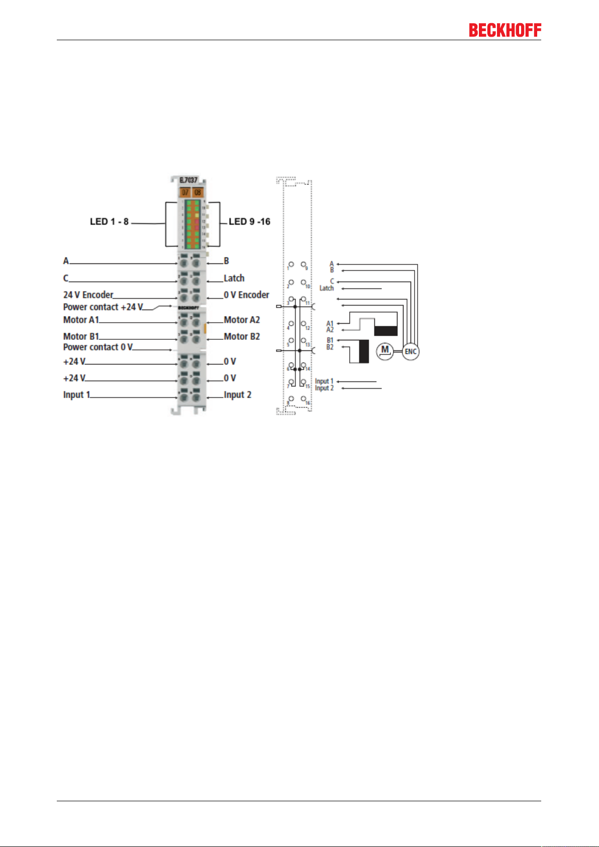
4.6.1 EL7037 - LEDs and connection ..........................................................................................48
4.6.2 EL7037 - General connection examples.............................................................................50
4.7 EL7047 ........................................................................................................................................... 53
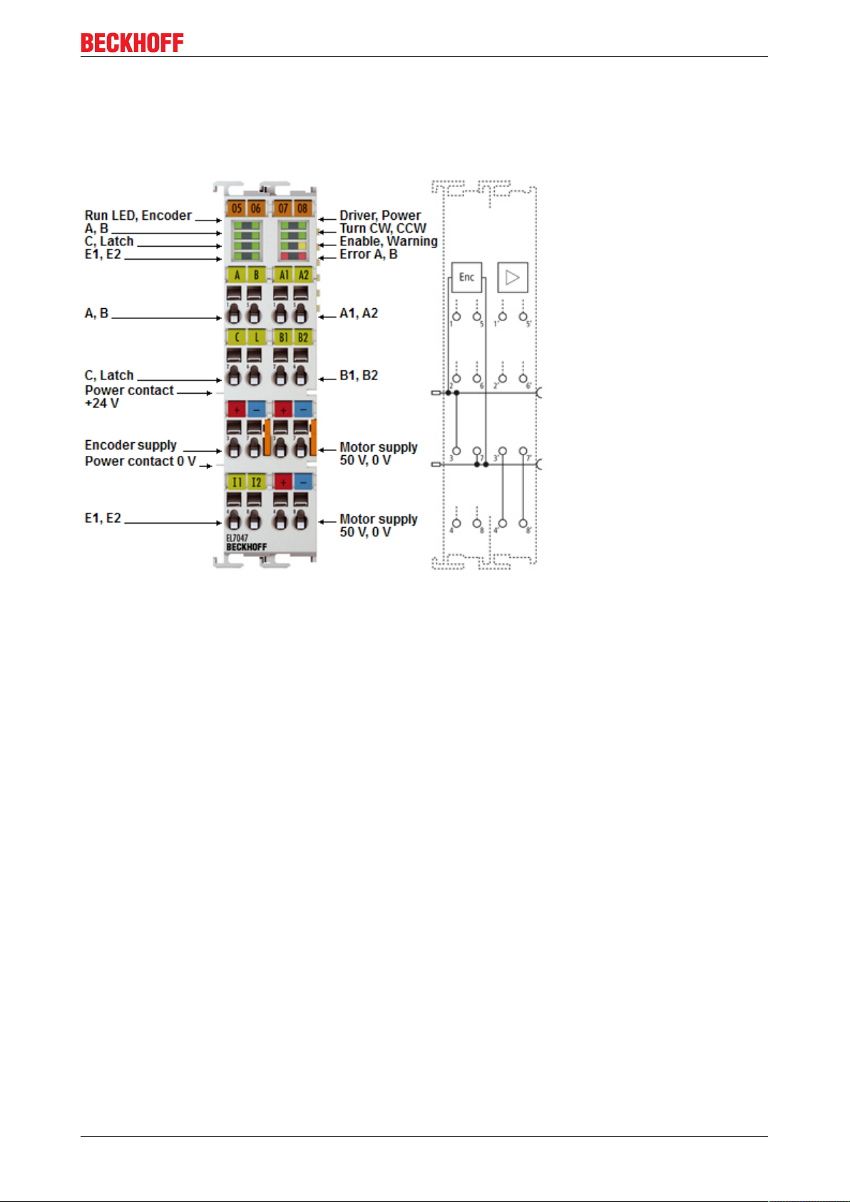
4.7.1 EL7047 - LEDs and connection ..........................................................................................53
4.7.2 EL7047 - General connection examples.............................................................................55
5 Commissioning........................................................................................................................................58
5.1 TwinCAT 2.1x ................................................................................................................................. 58
5.1.1 Installation of the TwinCAT real-time driver ........................................................................58
5.1.2 Notes regarding ESI device description..............................................................................62
5.1.3 Offline configuration creation (master: TwinCAT 2.x) .........................................................66
5.1.4 Online configuration creation ‘scanning’ (master: TwinCAT 2.x) ........................................72
5.1.5 EtherCAT slave process data settings................................................................................81
5.1.6 Configuration by means of the TwinCAT System Manager ................................................82
5.2 General Notes - EtherCAT Slave Application ................................................................................. 90
5.3 Start-up and parameter configuration ............................................................................................. 99
5.3.1 Process data .......................................................................................................................99
EL70x7 3Version 1.0
Page 4

Table of contents
5.3.2 Integration into the NC configuration ................................................................................104
5.3.3 Configuring the main parameters - Settings in the CoE register....................................... 109
5.3.4 Configuring the main parameter - Selecting the reference velocity ..................................112
5.3.5 Application example..........................................................................................................117
5.4 Operating modes .......................................................................................................................... 123
5.4.1 Overview ...........................................................................................................................123
5.4.2 Velocity direct....................................................................................................................125
5.4.3 Position controller .............................................................................................................128
5.4.4 Extended Velocity mode ...................................................................................................131
5.4.5 Extended Position mode ...................................................................................................134
5.4.6 Velocity sensorless ..........................................................................................................137
5.4.7 Basic principles: "Positioning interface" ............................................................................140
6 Configuration by means of the TwinCAT System Manager ..............................................................155
6.1 EL7037 ......................................................................................................................................... 155
6.1.1 Object description and parameterization - Profile-specific objects ...................................155
6.1.2 Object description and parameterization - standard objects.............................................166
6.2 EL7047 ......................................................................................................................................... 179
6.2.1 Object description and parameterization - Profile-specific objects ...................................179
6.2.2 Object description and parameterization - standard objects.............................................190
7 Error correction .....................................................................................................................................203
7.1 Diagnosis - Diag Messages .......................................................................................................... 203
8 Appendix ................................................................................................................................................208
8.1 UL notice....................................................................................................................................... 208
8.2 EtherCAT AL Status Codes .......................................................................................................... 210
8.3 Firmware EL/ES/EM/EPxxxx ........................................................................................................ 210
8.4 Firmware compatibility .................................................................................................................. 220
8.5 Restoring the delivery state .......................................................................................................... 220
8.6 Support and Service ..................................................................................................................... 222
EL70x74 Version 1.0
Page 5

Foreword
1 Foreword
1.1 Notes on the documentation
This description is only intended for the use of trained specialists in control and automation engineering who
are familiar with the applicable national standards.
It is essential that the following notes and explanations are followed when installing and commissioning
these components.
The responsible staff must ensure that the application or use of the products described satisfy all the
requirements for safety, including all the relevant laws, regulations, guidelines and standards.
Disclaimer
The documentation has been prepared with care. The products described are, however, constantly under
development.
For that reason the documentation is not in every case checked for consistency with performance data,
standards or other characteristics.
In the event that it contains technical or editorial errors, we retain the right to make alterations at any time
and without warning.
No claims for the modification of products that have already been supplied may be made on the basis of the
data, diagrams and descriptions in this documentation.
Trademarks
Beckhoff®, TwinCAT®, EtherCAT®, Safety over EtherCAT®, TwinSAFE®, XFC®and XTS® are registered
trademarks of and licensed by Beckhoff Automation GmbH.
Other designations used in this publication may be trademarks whose use by third parties for their own
purposes could violate the rights of the owners.
Patent Pending
The EtherCAT Technology is covered, including but not limited to the following patent applications and
patents:
EP1590927, EP1789857, DE102004044764, DE102007017835
with corresponding applications or registrations in various other countries.
The TwinCAT Technology is covered, including but not limited to the following patent applications and
patents:
EP0851348, US6167425 with corresponding applications or registrations in various other countries.
EtherCAT® is registered trademark and patented technology, licensed by Beckhoff Automation GmbH,
Germany
Copyright
© Beckhoff Automation GmbH & Co. KG, Germany.
The reproduction, distribution and utilization of this document as well as the communication of its contents to
others without express authorization are prohibited.
Offenders will be held liable for the payment of damages. All rights reserved in the event of the grant of a
patent, utility model or design.
EL70x7 5Version 1.0
Page 6
Foreword
1.2 Safety instructions
Safety regulations
Please note the following safety instructions and explanations!
Product-specific safety instructions can be found on following pages or in the areas mounting, wiring,
commissioning etc.
Exclusion of liability
All the components are supplied in particular hardware and software configurations appropriate for the
application. Modifications to hardware or software configurations other than those described in the
documentation are not permitted, and nullify the liability of Beckhoff Automation GmbH & Co. KG.
Personnel qualification
This description is only intended for trained specialists in control, automation and drive engineering who are
familiar with the applicable national standards.
Description of symbols
In this documentation the following symbols are used with an accompanying safety instruction or note. The
safety instructions must be read carefully and followed without fail!
Serious risk of injury!
Failure to follow the safety instructions associated with this symbol directly endangers the
DANGER
life and health of persons.
Risk of injury!
Failure to follow the safety instructions associated with this symbol endangers the life and
WARNING
health of persons.
Personal injuries!
Failure to follow the safety instructions associated with this symbol can lead to injuries to
CAUTION
persons.
Damage to the environment or devices
Failure to follow the instructions associated with this symbol can lead to damage to the en-
Attention
vironment or equipment.
Note
Tip or pointer
This symbol indicates information that contributes to better understanding.
EL70x76 Version 1.0
Page 7

1.3 Documentation issue staus
Version Comment
1.0 - Minor corrections
- Layout adaption
- 1st public issue
0.4 - Minor corrections
- Addenda EL7037
0.3 - Minor corrections
0.2 - Minor corrections
0.1 - Preliminary documentation
Foreword
EL70x7 7Version 1.0
Page 8

Foreword
1.4 Version identification of EtherCAT devices
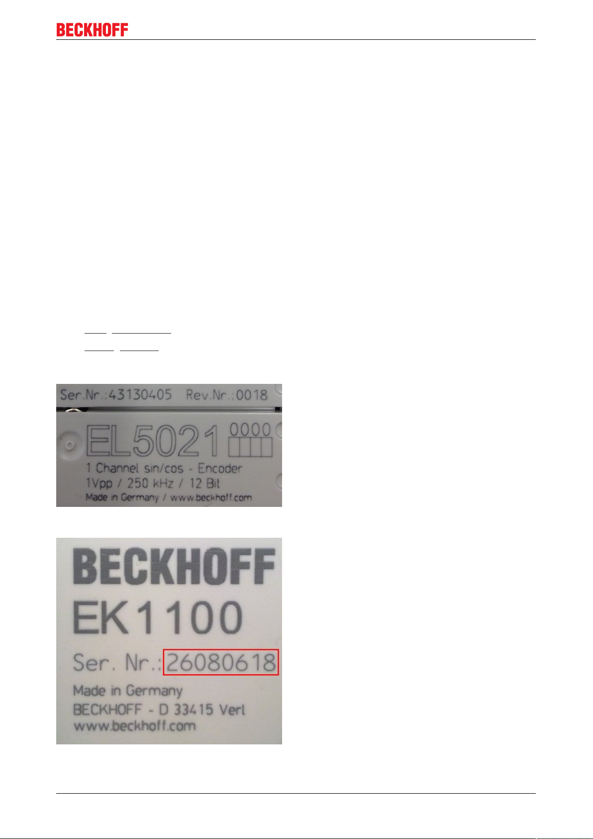
Designation
A Beckhoff EtherCAT device has a 14-digit designation, made up of
• family key
• type
• version
• revision
Example Family Type Version Revision
EL3314-0000-0016 EL terminal
(12 mm, nonpluggable
connection level)
CU2008-0000-0000CU device 2008 (8-port fast
ES3602-0010-0017 ES terminal
(12 mm, pluggable
connection level)
3314 (4-channel
thermocouple
terminal)
ethernet switch)
3602 (2-channel
voltage
measurement)
0000 (basic type) 0016
0000 (basic type) 0000
0010 (highprecision version)
0017
Notes
• the elements named above make up the technical designation
• The order designation, conversely, is made up of
- family key (EL, EP, CU, ES, KL, CX, etc.)
- type
- version
• The revision shows the technical progress, such as the extension of features with regard to the
EtherCAT communication, and is managed by Beckhoff.
In principle, a device with a higher revision can replace a device with a lower revision, unless specified
otherwise, e.g. in the documentation.
Associated and synonymous with each revision there is usually a description (ESI, EtherCAT Slave
Information) in the form of an XML file, which is available for download from the Beckhoff website.
The revision has been applied to the IP20 terminals on the outside since 2014/01, see fig. 1.
• The type, version and revision are read as decimal numbers, even if they are technically saved in
hexadecimal.
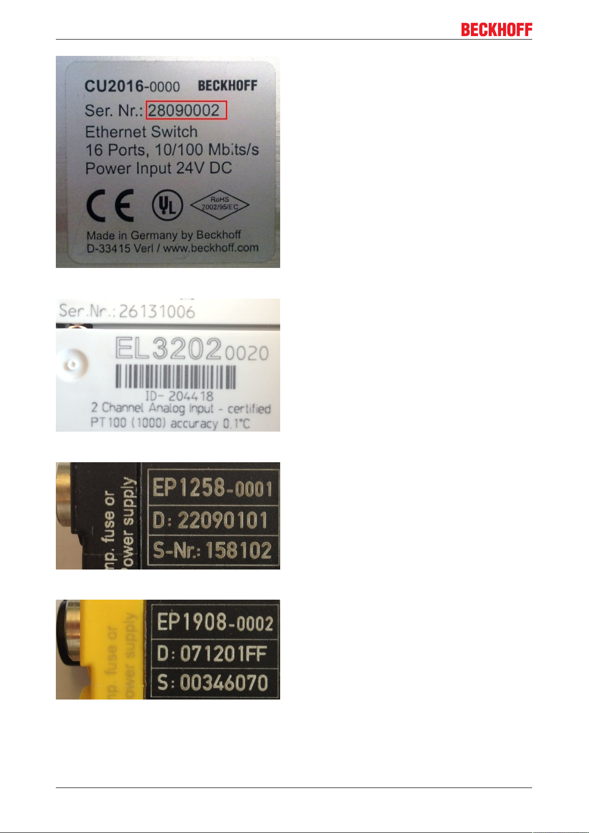
Identification number
Beckhoff EtherCAT devices from the different lines have different kinds of identification numbers:
Production lot/batch number/serial number/date code/D number
Serial number is the name generally given to the 8-digit number that is printed on the device or attached to it
on a sticker. This serial number indicates the as-built status on delivery and thus ambiguously marks a whole
production lot.
Structure of the serial number: KK YY FF HH
KK - week of production (CW, calendar week)
YY - year of production
FF - firmware version
HH - hardware version
Example with ser. no.: 12063A02: 12 - production week 12 06 - production year 2006 3A - firmware version
3A 02 - hardware version 02
EL70x78 Version 1.0
Page 9
Foreword
Exceptions can occur in the IP67 area , where the following syntax can be used (see respective device
documentation):
Syntax: D ww yy x y z u
D - prefix designation
ww - calendar week
yy - year
x - firmware version of the bus PCB
y - hardware version of the bus PCB
z - firmware version of the I/O PCB
u - hardware version of the I/O PCB
Example: D.22081501 calendar week 22 of the year 2008 firmware version of bus PCB: 1 hardware version
of bus PCB: 5 firmware version of I/O PCB: 0 (no firmware necessary for this PCB) hardware version of I/O
PCB: 1
Unique serial number/ID
Beyond that there are some series in which each individual module has its own unique, sequential serial
number.
See also the further documentation in the area
• IP67: EtherCAT Box
• Safety: TwinSafe
Examples of markings:
Fig.1: EL5021 EL terminal, standard IP20 IO device with batch number and revision ID (since 2014/01)
Fig.2: EK1100 EtherCAT coupler, standard IP20 IO device with batch number
EL70x7 9Version 1.0
Page 10
Foreword
Fig.3: CU2016 switch with batch number
Fig.4: EL3202-0020 with batch numbers 26131006 and unique D-number 204418
Fig.5: EP1258-00001 IP67 EtherCAT Box with batch number 22090101 and serial number 158102
Fig.6: EP1908-0002 IP76 EtherCAT Safety Box with batch number 071201FF and serial number 00346070
EL70x710 Version 1.0
Page 11
Foreword
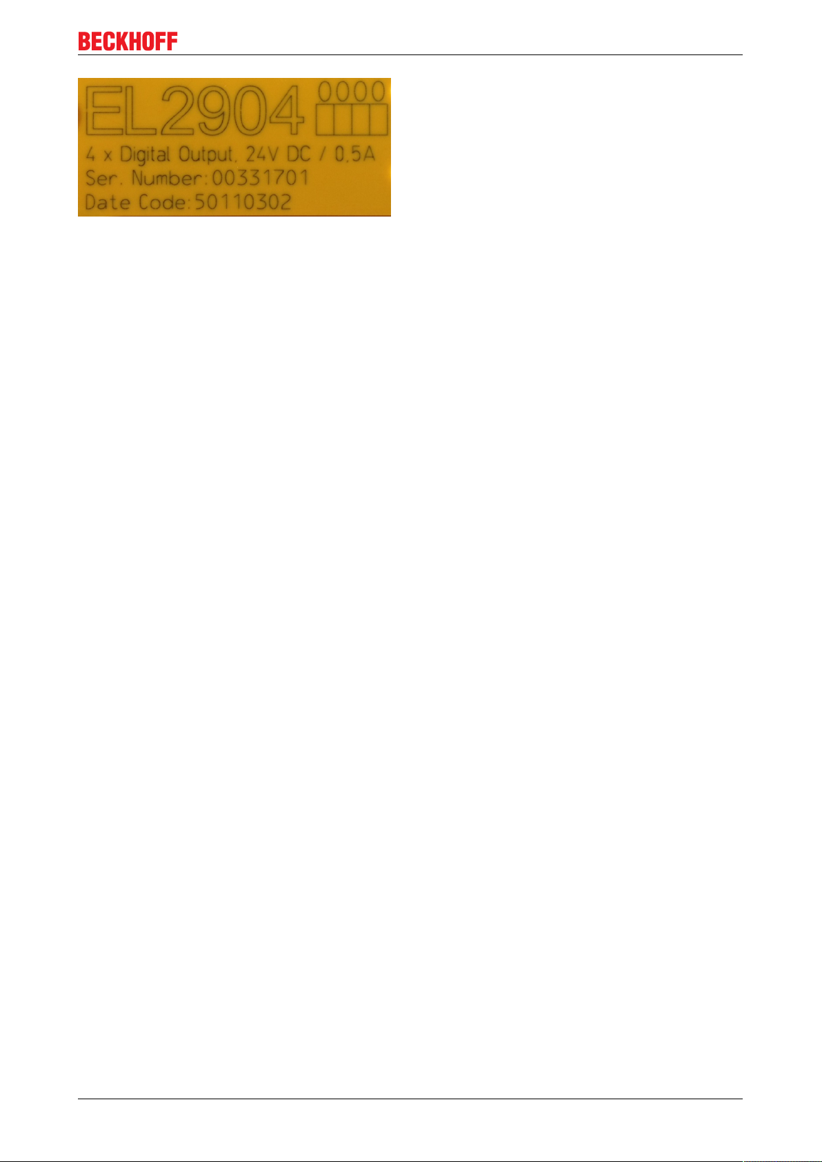
Fig.7: EL2904 IP20 safety terminal with batch number/date code 50110302 and serial number 00331701
EL70x7 11Version 1.0
Page 12
Product overview
2 Product overview
2.1 EL7037
2.1.1 EL7037 - Introduction
Fig.8: EL7037
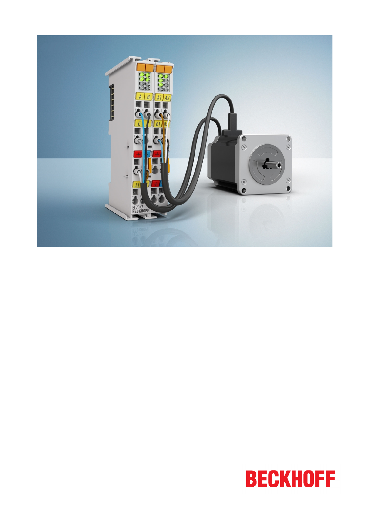
Stepper motor terminal, 24 V DC, 1,5 A, vector control
The The EL7037 EtherCAT Terminal is intended for stepper motors with low performance range. The PWM
output stages cover a wide range of voltages and currents. Together with two inputs for limit switches, they
are located in the EtherCAT Terminal.
The EL7037 can be adjusted to the motor and the application by changing just a few parameters. Stepper
motors from the AS10xx series can be operated with vector control. This control technique offers various
benefits, such as better dynamics and lower power consumption.
Together with a stepper motor, the EL7037 represents an inexpensive compact drive.
Quick links
Connection instructions
• Section "Installation and wiring",
- LEDs and pin assignment [}48]
- Connection examples [}50]
Commissioning instructions
• Section "Commissioning",
- Installation under TwinCAT [}58]
- Integration into the NC configuration [}104]
- Basic principles: "Positioning interface" [}140]
EL70x712 Version 1.0
Page 13

Configuration instructions
• Section "Commissioning",
- Configuring the main parameters - Settings in the CoE register [}109]
- Configuring the main parameters - NC settings [}112]
• Section "Configuration with the TwinCAT System Manager",
- Object description and parameterization [}155]
Application example
• Section "Commissioning",
- Application example [}117]
Product overview
EL70x7 13Version 1.0
Page 14

Product overview
2.1.2 EL7037 - Technical data
Technical data EL7037
Number of outputs 1 stepper motor, 2 phases
Number of digital inputs 2 limit position, 4 for an encoder system
Number of digital outputs 1 configurable for brake (0.5 A)
Supply voltage 24 V DC (-15 %/+20 %)
Output current 1.5 A (overload- and short-circuit-proof)
Operating modes Standard mode (velocity direct / position controller)
Field-oriented control (extended velocity mode /
extended position mode)
Sensorless operation
Travel distance control (positioning interface)
Maximum step frequency 1000, 2000, 4000, 8000 or 16000 full steps/s
(configurable)
Step pattern up to 64-fold micro stepping (automatic switching,
speed-dependent)
Current controller frequency approx. 30 kHz
Encoder pulse frequency maximum 400,000 increments/s (4-fold evaluation)
Input signal voltage "0" -3 V … 2 V
Input signal voltage "1" 2.5 V … 28 V
Input current typ. 5 mA
Diagnostics LED Warning strand A and B, error strand A and B, power,
enable
Resolution approx. 5,000 positions in typical applications (per
revolution)
Power supply via the E-bus, encoder/driver stage: via the power
contacts, motor: via terminal contacts
Current consumption from the E-bus typ. 100 mA
Electrical isolation 500 V (E-bus/signal voltage)
Support NoCoEStorage [}33]
Configuration no address setting required
Weight approx. 60 g
Permissible ambient temperature range during
operation
Permissible ambient temperature range during
storage
Permissible relative humidity 95%, no condensation
Dimensions (W x H x D) approx. 15 mm x 100 mm x 70 mm
Installation on 35 mm mounting rail according to EN 60715
Vibration / shock resistance Conforms to EN 60068-2-6 / EN 60068-2-27
EMC immunity/emission according to EN 61000-6-2 / EN 61000-6-4
EMC category Category C3 - standard
Protection class IP 20
Installation position
Approval CE
yes
Configuration via TwinCAT System Manager
0℃ ... +55℃
-25°C ... + 85°C
(connected width: 12 mm)
according to IEC/EN 61800-3
Category C2, C1 - auxiliary filter required
see note [}45]!
EL70x714 Version 1.0
Page 15
2.2 EL7047
2.2.1 EL7047 - Introduction
Product overview
Fig.9: EL7047
Stepper motor terminal, 50 V DC, 5 A, vector control
The EL7047 EtherCAT Terminal is intended for stepper motors with medium performance range. The PWM
output stages cover a wide range of voltages and currents. Together with two inputs for limit switches, they
are located in the EtherCAT Terminal.
The EL7047 can be adjusted to the motor and the application by changing just a few parameters. 64-fold
micro-stepping ensures particularly quiet and precise motor operation.
Field-oriented control can be selected for AS1xxx series stepper motors from Beckhoff Automation. This
offers a number of advantages, such as a better dynamics and lower power consumption.
Together with a stepper motor and an encoder, the EL7047 represents an inexpensive small servo axis.
The LEDs indicate status, warning and error messages as well as possibly active limitations.
Quick links
Connection instructions
• Section "Installation and wiring",
- LEDs and pin assignment [}53]
- Connection examples [}55]
Commissioning instructions
• Section "Commissioning",
- Installation under TwinCAT [}58]
- Integration into the NC configuration [}104]
- Basic principles: "Positioning interface" [}140]
EL70x7 15Version 1.0
Page 16

Product overview
Configuration instructions
• Section "Commissioning",
- Configuring the main parameters - Settings in the CoE register [}109]
- Configuring the main parameters - NC settings [}112]
• Section "Configuration with the TwinCAT System Manager",
- Object description and parameterisation [}179]
Application example
• Section "Commissioning",
- Application example [}117]
EL70x716 Version 1.0
Page 17

Product overview
2.2.2 EL7047 - Technical data
Technical data EL7047
Number of outputs 1 stepper motor, 2 phases
Number of digital inputs 2 limit position, 4 for an encoder system
Number of digital outputs 1 configurable for brake (0.5 A)
Supply voltage 8 … 50 V DC
Output current 5 A (overload- and short-circuit-proof)
Operating modes Standard mode (velocity direct / position controller)
Field-oriented control (extended velocity mode /
extended position mode)
Sensorless operation
Travel distance control (positioning interface)
Maximum step frequency 1000, 2000, 4000, 8000 or 16000 full steps/s
(configurable)
Step pattern up to 64-fold micro stepping (automatic switching,
speed-dependent)
Current controller frequency approx. 30 kHz
Encoder pulse frequency maximum 400,000 increments/s (4-fold evaluation)
Input signal voltage "0" -3 V … 2 V
Input signal voltage "1" 2.5 V … 28 V
Input current typ. 5 mA
Diagnostics LED Warning strand A and B, error strand A and B, power,
enable
Resolution approx. 5,000 positions in typical applications (per
revolution)
Power supply via the E-bus, encoder/driver stage: via the power
contacts, motor: via terminal contacts
Current consumption from the E-bus typ. 140 mA
Electrical isolation 500 V (E-bus/signal voltage)
Support NoCoEStorage [}33]
Configuration no address setting required
Weight approx. 105 g
Permissible ambient temperature range during
operation
Permissible ambient temperature range during
storage
Permissible relative humidity 95%, no condensation
Dimensions (W x H x D) approx. 27 mm x 100 mm x 70 mm
Installation on 35 mm mounting rail according to EN 60715
Vibration / shock resistance Conforms to EN 60068-2-6 / EN 60068-2-27
EMC immunity/emission according to EN 61000-6-2 / EN 61000-6-4
EMC category Category C3 - standard
Protection class IP 20
Installation position
Approval CE
yes
Configuration via TwinCAT System Manager
0℃ ... +55℃
-25°C ... + 85°C
(connected width: 24 mm)
according to IEC/EN 61800-3
Category C2, C1 - auxiliary filter required
see note [}45]!
EL70x7 17Version 1.0
Page 18

Product overview
2.3 Technology
The EL70x7 stepper motor terminal integrates a compact Motion Control solution for stepper motors in a
very compact design.
The user can control stepper motors in the low to medium performance range. With an output current of up
to 5 A, the EL7047 can achieve a considerable torque of e.g. 5 Nm at a standard stepper motor. The supply
voltage of up to 50 VDC allows high speeds with good torque and thus high mechanical performance. The
stepper motor and an incremental encoder can be connected directly to the EL70x7.
The stepper motor terminal provides three basic modes of operation.
In standard mode [}22] all unipolar and bipolar stepper motors that comply with the specifications of the
corresponding EL70x7 can be controlled. Two currents with sine/cosine curve are provided. The current is
clocked with 64 kHz and resolved with up to 64-fold microstepping to achieve a smooth current.
Extended mode [}23] is based on field-oriented control. This mode can only be used for stepper motors
from Beckhoff. The current is not only provided, but controlled in a comprehensive manner. Typical stepper
motor problems such as pronounced resonance are therefore finally a thing of the past. Furthermore, the
current is adjusted depending on the load, thereby enabling considerable energy savings and lower thermal
loads at the stepper motor.
In sensorless mode [}25] stepper motors from Beckhoff can be controlled load-dependent without a
feedback system.
Realisation of more demanding positioning tasks
More demanding positioning tasks can be realised via the TwinCAT automation software from Beckhoff. Like
other axes, the stepper motor terminals are integrated via the TwinCAT System Manager and can be used
like standard servo axes. Special stepper motor features, such as speed reduction in the event of large
following errors, are automatically taken into account via the stepper motor axis option. The effort for
changing from a servomotor to a stepper motor - and back - is no greater than changing from one fieldbus to
another one under TwinCAT.
The output stages of the stepper motor terminals have an overload protection in the form of an
overtemperature warning and switch-off. Together with short circuit detection, diagnostic data are accessible
in the process image of the controller. In addition, this status is displayed by the Bus Terminal LEDs, along
with other information. The output stage is switched on via an Enable-Bit. The motor current can be set and
reduced via a parameter value.
Optimum adaptation to the motor and the implementation of energy-saving features require minimum
programming effort. Since all data are set in the form of parameters in the CoE register, it is easily possible
to replace an EtherCAT Terminal or store certain parameters for transfer to the next project. It is therefore no
longer necessary to transfer certain potentiometer settings or to document DIP switch settings.
2.3.1 Stepper motor
Stepper motors are electric motors and are comparable with synchronous motors. The rotor is designed as a
permanent magnet, while the stator consists of a coil package. The frequency of the stator rotary field is
always in a fixed ratio relative to the rotor speed. In contrast to synchronous motors, stepper motors have a
large number of pole pairs. In a minimum control configuration, the stepper motor is moved from pole to pole,
or from step to step.
Stepper motors have been around for many years. They are robust, easy to control, and provide high torque.
In many applications, the step counting facility saves expensive feedback systems. Even with the
increasingly widespread use of synchronous servomotors, stepper motors are by no means "getting long in
the tooth". They are considered to represent mature technology and continue to be developed further in
order to reduce costs and physical size, increase torque and improve reliability. For a standard stepper
motor with 200 full steps, the best possible positioning accuracy is approx. 1.8°.
EL70x718 Version 1.0
Page 19

Product overview
Today, the most widely used type in industry is the hybrid stepper motor type. In this type of motor the rotor
consists of a toothed iron core with one or a few permanent magnets in the rotor core. The rotor is designed
such that the polarity of successive teeth is inverse. This enables the production of motors with a high
number of steps, which is essential for positioning accuracy, combined with a relatively high torque. The
electrical behaviour of such a hybrid stepper motor is comparable with a multipole synchronous servomotor.
However, thanks to the synchronous toothing of stator and rotor, hybrid stepper motors offer a significantly
higher cogging torque.
Hybrid stepper motors with two or more phases are available on the market. Since the terminals described
here are designed for two-phase motors, the description focuses on the two-phase type, with the phases
referred as A and B in this documentation.
The development of the EL70x7 EtherCAT Terminals for the Beckhoff EtherCAT Terminal system opens up
new fields of application. The use of microstepping, the latest semiconductor technology and field-oriented
control (only with Beckhoff motors) offers many advantages:
• smoother operation
• avoidance of resonance
• reduced energy consumption
• lower thermal load on the motor
• minimum electromagnetic emissions
• long cable lengths
• simpler handling
• reduced size of the power electronics
• simple integration into higher-level systems
• integrated feedback system
Stepper motor parameters
• Mechanical system
Irrespective of the drive and the stepper motor itself, the configuration of the mechanism attached to the
motor shaft has significant influence on the achievable control quality.
Natural resonances, load resonances, gear backlash (loose) and static friction have negative affect on the
controllability of the drive system. This often requires "softer" controller parameterisation, which in turn leads
to a higher position lag in the system. Sliding friction can result in reduced efficiency (due to increased
energy demand), but on the other hand it can have a positive effect on the control stability, due to its
dampening effect.
As a general rule, the "stiffer" the mechanics of a drive system, the easier it is to control, which is beneficial
for achieving a small position lag in the drive system.
• Speed
Stepper motors have low maximum speed, which is usually specified as a maximum step frequency.
• Number of phases
Motors with 2 to 5 phases are common. The EL70x7 EtherCAT Terminals support 2-phase motors. 4-phase
motors are basically 2-phase motors with separate winding ends. They can be connected directly to the
EtherCAT Terminal.
• Torque
Refers to the maximum motor torque at different speeds. This parameter is usually represented by a
characteristic curve. Stepper motors have comparatively high torque in the lower speed range. In many
applications, this enables them to be used directly without gearing. Compared with other motors, stepper
motors can quite easily provide a holding moment of the same order of magnitude as the torque.
EL70x7 19Version 1.0
Page 20
Product overview
• Cogging torque
In many cases the stepper motors design results in high cogging torque, which can lead to relatively strong
natural resonance in a motor- and load-dependent speed range. In relation to the cogging torque, increased
inertia often leads to a less strong resonance and smoother operation.
• Mass moment of inertia
In standard mode, the key parameter of the mechanical system is the mass moment of inertia JΣ. It is
essentially composed of the mass moment of inertia of the stepper motor rotor JM and the mass moment of
inertia of the connected load JL. The friction moment J
neglected in a first approximation.
and the moment of inertia of the encoder J
fric
can be
Enc
JƩ ≈ JM + J
L
The ratio between the load torque and the motor torque is defined by the constant kJ.
kJ ≈ JL / J
M
Fig.10: Simplified representation of the mass moments of inertia
As a first approximation, the coupling of the individual masses over the rotor shaft can be modelled as twomass oscillator. The resonance frequency between the motor and the encoder lies in a relatively high
frequency range, which is usually not relevant for stepper motor drives and is suppressed within the drive by
low-pass filtering. The resonance frequency between the motor and the load is frequently in the range
between 20 and 500 Hz. It is therefore often in the operating range of the drive control. Design measures to
reduce the influence of the load resonance include a small load ratio kJ and a rigid coupling of the motor
shaft to the connected load.
• Resonance
At certain speeds, stepper motors run less smoothly. This phenomenon is particularly pronounced when the
motor runs without coupled load, in which case it may even stop (in standard mode). This is caused by
resonance. A distinction can roughly be made between
• resonances in the lower frequency range up to approx. 250Hz; and
• resonances in the medium to upper frequency range.
Resonances in the medium to upper frequency range essentially result from electrical parameters such as
inductance of the motor winding and supply line capacity. They can be controlled relatively easily through
high pulsing of the control system.
Resonances in the lower range essentially result from the mechanical motor parameters. Apart from their
impact on smooth running, such resonances can lead to significant loss of torque, or even loss of step of the
motor, and are therefore particularly undesirable.
In principle, the stepper motor represents an oscillatory system (comparable to a mass/spring system),
consisting of the moving rotor with a moment of inertia and a magnetic field that creates a restoring force that
acts on the rotor. Moving and releasing the rotor creates a damped oscillation. If the control frequency
corresponds to the resonance frequency, the oscillation is amplified, so that in the worst case the rotor will
no longer follow the steps, but oscillate between two positions.
The EL70x7 EtherCAT Terminals prevent this effect thanks to their field-oriented control (Extended
Operation Modes) for all Beckhoff stepper motors.
EL70x720 Version 1.0
Page 21

Product overview
•Torque constant
In the Extended Operation Modes the torque constant kT is used as an additional parameter for the
mechanical controlled system. It indicates the ratio between the torque-forming motor current and the active
torque at the shaft. However, since the field-oriented operating mode is not common for stepper motors, the
torque constant is usually not listed in the motor data sheet.
Electrical system
• Nominal voltage, supply voltage and winding resistance
Under steady-state conditions, the rated current at the rated voltage depends on the winding resistance. This
voltage should not be confused with the supply voltage of the power output stage in the EtherCAT Terminal.
The EL70x7 applies a controlled current to the motor winding. If the supply voltage falls below the nominal
voltage, the power output stage can no longer apply the full current, resulting in a loss of torque. It is
desirable to aim for systems with small winding resistance and high supply voltage in order to limit warming
and achieve high torque at high speeds.
• Induced countervoltage
Like servomotors, hybrid stepper motors induce a voltage ui [Vs/rad] in the stator winding of the motor, which
is proportional to the speed. It is also referred to as Back Electromotive Force (BEMF). In conjunction with
the DC link voltage (motor voltage), the induced countervoltage determines the physically achievable
maximum speed of the motor.
The ratio of the magnitude of the induced countervoltage and the motor speed varies depending on the
design and is described via the voltage constant ke.
ui = ke·ω
The motor parameter ke [mV/(rad/s)] is required for step loss recognition without encoder and for sensorless
control.
For stepper motors where the voltage constant is not specified in the data sheet, it can be relatively easily
determined using a digital multimeter. To this end the motor to be measured must be operated (within the
rated speed range) by an auxiliary motor via a coupling with constant speed. The motor phases of the motor
to be measured must be open (not connected to the terminal or shorted). The multimeter can then be used
to determine the RMS value of the induced countervoltage, and therefore the voltage constant, at one of the
two open motor phases (A or B).
m
• Step angle
The step angle indicates the angle travelled during each step. Typical values are 3.6°, 1.8° and 0.9°. This
corresponds to 100, 200 and 400 steps per motor revolution. Together with the downstream transmission
ratio, this value is a measure for the positioning accuracy. For technical reasons, the step angle cannot be
reduced below a certain value. Positioning accuracy can only be improved further by mechanical means
(transmission). An elegant solution for increasing the positioning accuracy is the microstepping function
offered by the EL70x7. It enables up to 64 intermediate steps. The smaller "artificial" step angle has a further
positive effect: The drive can be operated at higher speed, yet with the same precision. The maximum speed
is unchanged, despite the fact that the drive operates at the limit of mechanical resolution.
• Winding resistance, winding inductance
The winding inductance and winding resistance of the stepper motor stator determine the electrical motor
time constant Te = L / R, which is a key parameter for current controller configuration.
Specifying the stepper motor
1. Determine the required positioning accuracy and hence the step resolution. The first task is to
determine the maximum resolution that can be achieved. The resolution can be increased via
mechanical gear reduction devices such as spindles, gearing or toothed racks. The 64-fold
microstepping of the stepper motor terminals also has to be taken into account.
EL70x7 21Version 1.0
Page 22
Product overview
2. Determine mass m and moment of inertia (J) of all parts to be moved
3. Calculate the acceleration resulting from the temporal requirements of the moved mass.
4. Calculate the forces from mass, moment of inertia, and the respective accelerations.
5. Convert the forces and velocities to the rotor axis, taking account of efficiencies, moments of friction
and mechanical parameters such as gear ratio. It is often best to start the calculation from the last
component, usually the load. Each further element transfers a force and velocity and leads to further
forces or torques due to friction. During positioning, the sum of all forces and torques acts on the
motor shaft. The result is a velocity/torque curve that the motor has to provide.
6. Using the characteristic torque curve, select a motor that meets these minimum requirements. The
moment of inertia of the motor has to be added to the complete drive. Verify your selection. In order to
provide an adequate safety margin, the torque should be oversized by 20% to 30%. The optimisation
is different if the acceleration is mainly required for the rotor inertia. In this case, the motor should be
as small as possible.
7. Test the motor under actual application conditions: Monitor the housing temperatures during
continuous operation. If the test results do not confirm the calculations, check the assumed
parameters and boundary conditions. It is important to also check side effects such as resonance,
mechanical play, settings for the maximum operation frequency and the ramp slope.
8. Different measures are available for optimising the performance of the drive: using lighter materials or
hollow instead of solid body, reducing mechanical mass. The control system can also have significant
influence on the behaviour of the drive. The Bus Terminal enables operation with different supply
voltages. The characteristic torque curve can be extended by increasing the voltage. In this case, a
current increase factor can supply a higher torque at the crucial moment, while a general reduction of
the current can significantly reduce the motor temperature. For specific applications, it may be
advisable to use a specially adapted motor winding.
2.3.2 Standard mode
Stepper motors were originally operated with very simple output stages, which were only able to switch the
voltage of the motor phases separately (nowadays current control takes place via PWM with pulse-width
modulation as standard). Initially the motor phases there were controlled individually in turn. A switching
sequence in the positive direction of rotation corresponds to the switching sequence (+A, +B, -A, -B).
Sequential switching results in rather irregular operation in this mode. In order to make the operation
smoother, so-called microstepping was introduced later, in which the four set voltages were extended by
intermediate values (e.g. from a stored sine table). These days, microstepping based on 64 steps is
commonly used.
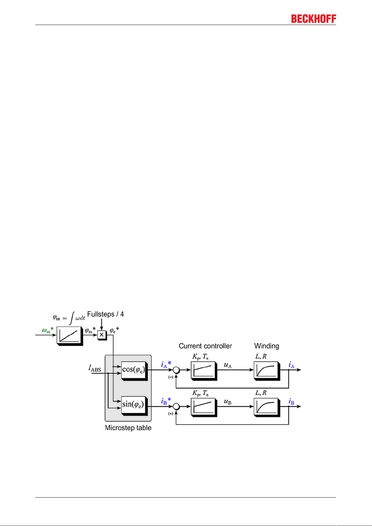
Fig.11: Control structure of a standard stepper motor drive
Neglecting the sampling resulting from the microstepping, the motor current I as function of the electrical
angle φe and of the magnitude of the motor current I
(when using a current controller) can be described as
ABS
follows:
I(φe) = IA+ jIB= I
cos(φe) + jI
ABS
ABS
sin(φe)
EL70x722 Version 1.0
Page 23
Product overview
Represented by magnitude and angle:
I(φe ) = I
ABS
· e
jφe
It follows that a rotation of the electrical angle φe is equivalent to four full steps. (A stepper motor with 200
full steps therefore has 50 pole pairs).
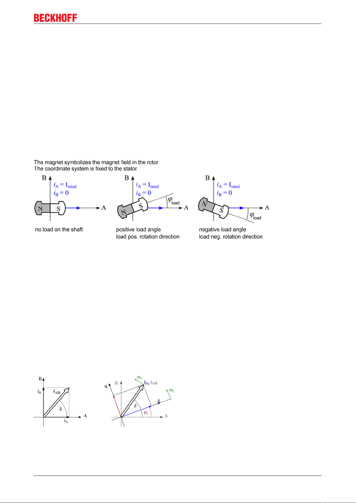
The shaft aligns itself if a constant current is set with no load at the motor shaft. Within a pole pairs the shaft
points in the direction of the active stator field.
If an external load is applied to the motor shaft, the shaft is turned out of the field direction, resulting in a load
angle (also referred to as angular displacement) (relative to an electric rotation of the angle φe). The load
angle depends on the design of the stepper motor itself, the motor current and the torque acting on the shaft.
The relationship is non-linear!
If the load angle exceeds a motor-dependent maximum value (i.e. if the maximum machine torque under
these boundary conditions is exceeded), the load torque can no longer be maintained by the motor. If the
shaft is turned further out of the rotary field, it "tips", resulting in one or more step losses. The "tip angle" may
vary between motor types. Often, it lies between around 45° and 65°.
Fig.12: Behaviour of the rotor under load
The load angle is of interest for the user, because it allows conclusions about the load on the shaft. It is
measured by evaluating the induced countervoltage* and can be used to optimise the drive system.
2.3.3 Field-oriented control
In the Extended Operation Modes the stepper motor is operated like a servomotor, based on the principle of
field-oriented control.
Function
The operating behaviour of the motor corresponds to that of a traditional DC motor, with commutation via a
mechanical commutator. With a constant exciter field, the torque of the DC machine is directly proportional to
the stator current and can be directly influenced by it. The exciter field is generated, depending on the
machine type, by permanent magnets or, with a separately excited DC machine, for example, via a separate
excitation winding.
Fig.13: Coordinate transformation of field-oriented control
For servomotors and also hybrid stepper motors, initially there is no direct link between the phase currents
and the torque. Field and torque are decoupled mathematically via Park's transformation. Two current
components, "d" for "direct" in field direction and "q" for "quadrature" in torque-forming direction, are
EL70x7 23Version 1.0
Page 24
Product overview
calculated from the phase currents. Via the torque-forming current component iq, the torque of the machine
can now be regulated directly, like for a DC machine.
A prerequisite is that the rotor position is available with sufficiently high accuracy. For a stepper motor the
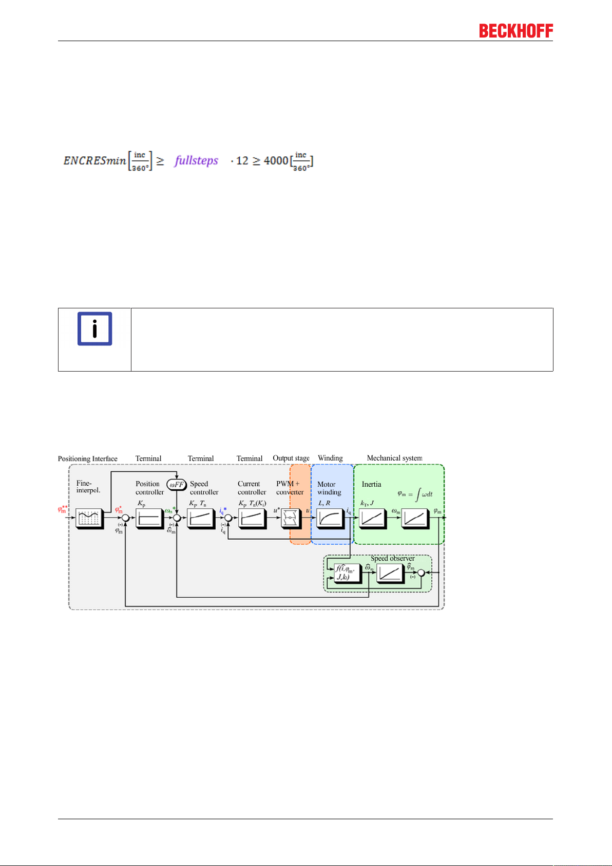
encoder resolution should be at least 4000 increments per mechanical revolution, in order to achieve
adequate positioning accuracy. The minimum encoder resolution also depends on the number of full steps
and can be calculated approximately as follows.
Fig.14: Calculation of the resolution
Commutation determination for Extended Operation Modes
Because the absolute actual position is not available for incremental encoders, on system start-up there is
no direct reference to the rotor position, which is required for field-oriented operation. Therefore, the
reference between the actual position and the rotor position must be generated at start-up via a commutation
determination process. During this process the rotor is moved forward and back several times up to two full
steps.
Commutation determination
• The maximum current should be set just below the rated motor current.
Note
• During commutation determination the rotor shaft should not be subject to an external
torque. If this condition is not met, the Extended Operation Modes cannot be used.
Control structure
The drive control structure is a cascade control structure with a position control loop and a lower-level speed
and current control loop. If a speed setpoint is specified, the external position control loop can be omitted.
Fig.15: Cascade control structure with field-oriented control (Extended Operating modes)
Motor dependency
Due to the fact that the control is strongly dependent on the motor parameters, the controller parameters and
motor behaviour itself, field-oriented control is limited to Beckhoff motors. This mode is not supported for
motors from other manufacturers.
Main advantages compared with standard mode
• Low current consumption (almost full load-dependence)
• High efficiency
• Consistent dynamics compared with standard mode
• Step losses are inherently avoided
EL70x724 Version 1.0
Page 25
Product overview
Requirement
• Encoder with sufficiently high resolution required (minimum 4000 [INC/360°])
• Slightly higher parametrisation effort required (speed controller)
• Commutation determination at startup (due to incremental encoder)
• Only possible with stepper motors from Beckhoff Automation (AS10xx)
2.3.4 Sensorless operation
Because the default operation of a stepper motor with a constant load-independent current is not energyefficient and leads to a permanently high thermal load, efforts are made to reduce this load.
Function
By analyzing the speed-proportional induced countervoltage, it is possible to control the stator current
depending on the load with the aid of a machine model (without sensor/encoder), thereby significantly
increasing the efficiency.
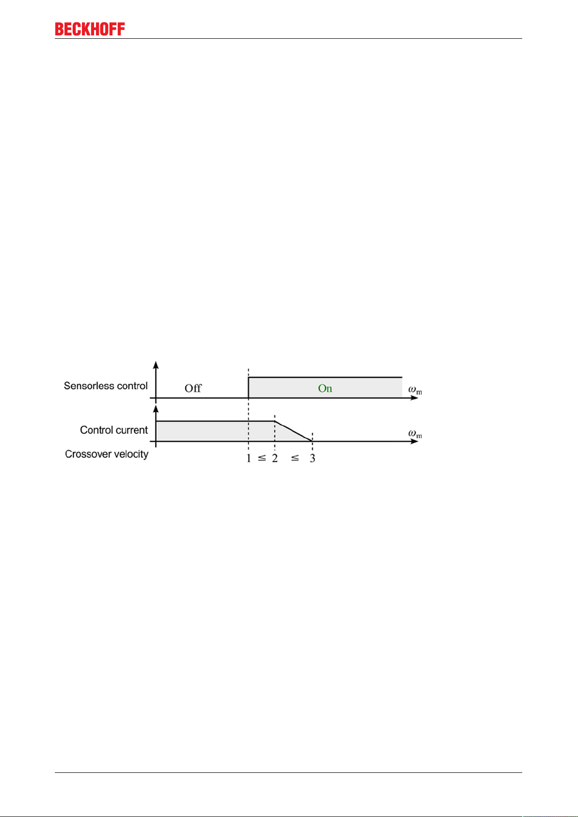
Since this operating mode requires a minimum amplitude of the magnitude of the induced countervoltage,
sensorless control only works in the medium and upper speed range. In the lower speed range the motor is
operated in standard mode. The changeover to sensorless operation take place via a programmable, motordependent switching speed. The switching speed is usually in the range between half and three revolutions
per second (crossover velocity 1).
When sensorless control is activated, the transient phenomenon results in a slight mechanical jerk of the
shaft, which is proportional to the load acting on the shaft.
Fig.16: Influence of the crossover velocity thresholds (1,2,3) on sensorless control
After switching on, the control current remains constant up to a second configurable speed and is reduced to
a third parameterizable speed via a linear ramp.
A long control current ramp leads to a stronger stabilization of the transient phenomenon of the control.
However, it also leads to a longer flowing constant motor current and therefore slightly higher losses.
Motor dependency
Due to the fact that the control is strongly dependent on the motor parameters, the controller parameters and
motor behaviour itself, sensorless operation is limited to Beckhoff motors. This mode is not supported for
motors from other manufacturers.
Parameterisation
Compared to the other operating modes, the parameterisation effort is relatively high. However, all the
required necessary parameters are pre-specified via a startup list for the respective motor types. All that is
required during commissioning is an adjustment of the speed control parameters, due to the given mass
inertia ratios of the connected loads in the mechanical system.
For the speed controller, in principle the same dependence on the mass moment of inertia and the torque
constant applies as in the Extended Operation Modes. Thanks to the lower-level sensorless control it is,
however, possible to achieve a better overall result through different parameterisation.
EL70x7 25Version 1.0
Page 26

Product overview
All parameters required for sensorless operation can be found in the table "Overview of parameter settings
for individual operating modes [}124]".
Summary
In this mode, above a minimum speed the motor current without encoder is controlled load-dependent. In
this way it is possible to realise a particularly cost-effective drive in combination with high efficiency. The
achievable dynamic performance of the drive control is slightly reduced compared to the other operating
modes.
Advantages compared with standard mode
• Low current consumption (almost full load-dependence)
• High efficiency
• no encoder required
Prerequisites
• relatively high parameterisation effort required (speed controller + additional parameters)
• minimum speed required (if the speed is too low, the motor automatically switches to standard mode)
• dynamic performance somewhat lower than in standard mode
• Only possible with stepper motors from Beckhoff Automation (AS10xx)
2.4 Start-up
For commissioning:
• Install the EL70x7 as described in section Installation [}38].
• Configure the EL70x7 in TwinCAT as described in section Commissioning [}58].
EL70x726 Version 1.0
Page 27
Basics communication
3 Basics communication
3.1 EtherCAT basics
Please refer to the chapter EtherCAT System Documentation for the EtherCAT fieldbus basics.
3.2 EtherCAT cabling – wire-bound
The cable length between two EtherCAT devices must not exceed 100 m. This results from the FastEthernet
technology, which, above all for reasons of signal attenuation over the length of the cable, allows a maximum
link length of 5 + 90 + 5 m if cables with appropriate properties are used. See also the Design
recommendations for the infrastructure for EtherCAT/Ethernet.
Cables and connectors
For connecting EtherCAT devices only Ethernet connections (cables + plugs) that meet the requirements of
at least category 5 (CAt5) according to EN 50173 or ISO/IEC 11801 should be used. EtherCAT uses 4 wires
for signal transfer.
EtherCAT uses RJ45 plug connectors, for example. The pin assignment is compatible with the Ethernet
standard (ISO/IEC 8802-3).
Pin Color of conductor Signal Description
1 yellow TD + Transmission Data +
2 orange TD - Transmission Data -
3 white RD + Receiver Data +
6 blue RD - Receiver Data -
Due to automatic cable detection (auto-crossing) symmetric (1:1) or cross-over cables can be used between
EtherCAT devices from Beckhoff.
Recommended cables
Suitable cables for the connection of EtherCAT devices can be found on the Beckhoff web-
Note
site!
E-Bus supply
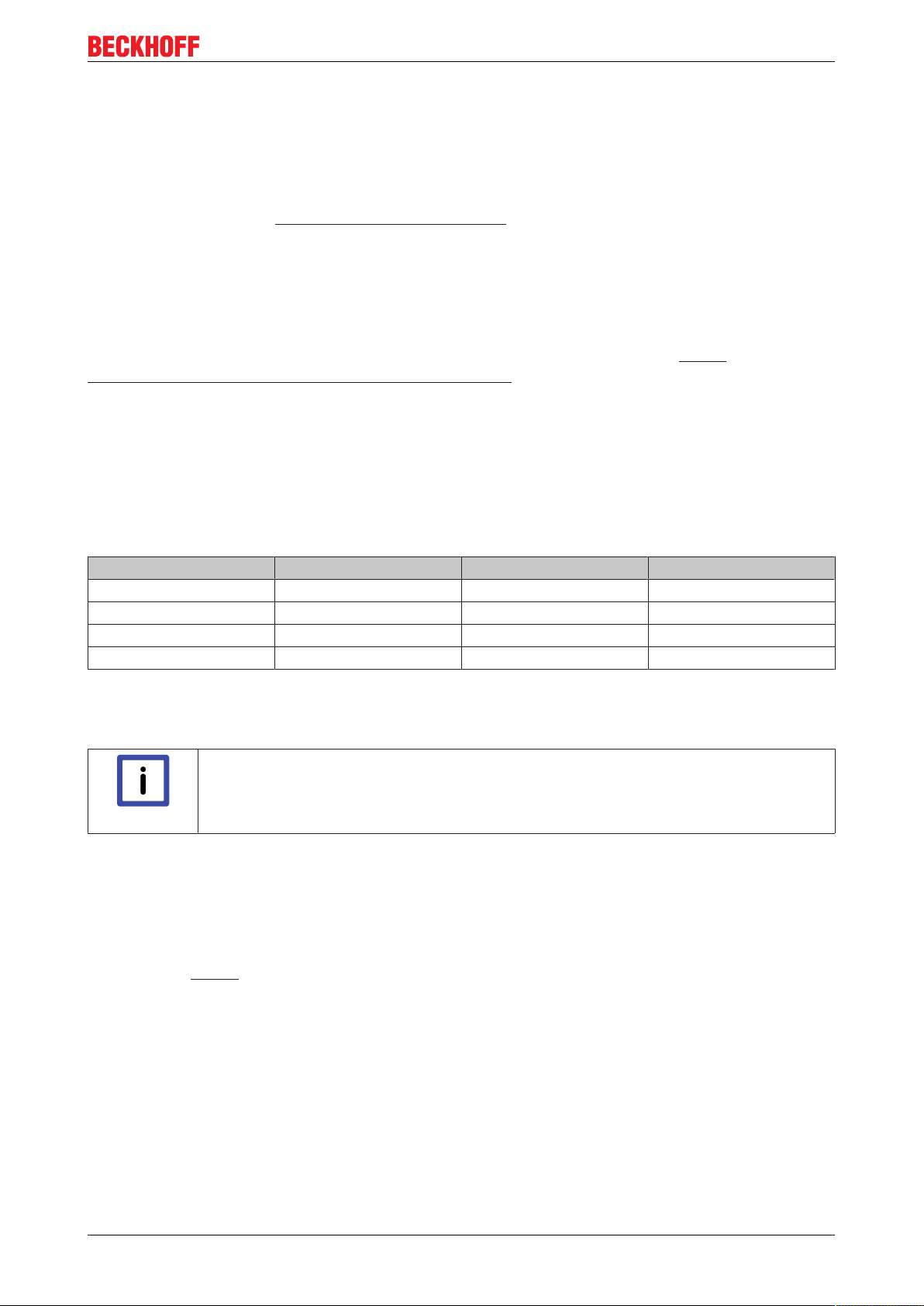
A bus coupler can supply the EL terminals added to it with the E-bus system voltage of 5 V; a coupler is
thereby loadable up to 2A as a rule (see details in respective device documentation).
Information on how much current each EL terminal requires from the E-bus supply is available online and in
the catalogue. If the added terminals require more current than the coupler can supply, then power feed
terminals (e.g. EL9410) must be inserted at appropriate places in the terminal strand.
The pre-calculated theoretical maximum E-bus current is displayed in the TwinCAT System Manager. A
shortfall is marked by a negative total amount and an exclamation mark; a power feed terminal is to be
placed before such a position.
EL70x7 27Version 1.0
Page 28
Basics communication
Fig.17: System manager current calculation
Caution! Malfunction possible!
The same ground potential must be used for the E-Bus supply of all EtherCAT terminals in
Attention
a terminal block!
3.3 General notes for setting the watchdog
ELxxxx terminals are equipped with a safety feature (watchdog) that switches off the outputs after a
specifiable time e.g. in the event of an interruption of the process data traffic, depending on the device and
settings, e.g. in OFF state.
The EtherCAT slave controller (ESC) in the EL2xxx terminals features 2 watchdogs:
• SM watchdog (default: 100 ms)
• PDI watchdog (default: 100 ms)
SM watchdog (SyncManager Watchdog)
The SyncManager watchdog is reset after each successful EtherCAT process data communication with the
terminal. If no EtherCAT process data communication takes place with the terminal for longer than the set
and activated SM watchdog time, e.g. in the event of a line interruption, the watchdog is triggered and the
outputs are set to FALSE. The OP state of the terminal is unaffected. The watchdog is only reset after a
successful EtherCAT process data access. Set the monitoring time as described below.
The SyncManager watchdog monitors correct and timely process data communication with the ESC from the
EtherCAT side.
PDI watchdog (Process Data Watchdog)
If no PDI communication with the EtherCAT slave controller (ESC) takes place for longer than the set and
activated PDI watchdog time, this watchdog is triggered.
PDI (Process Data Interface) is the internal interface between the ESC and local processors in the EtherCAT
slave, for example. The PDI watchdog can be used to monitor this communication for failure.
The PDI watchdog monitors correct and timely process data communication with the ESC from the
application side.
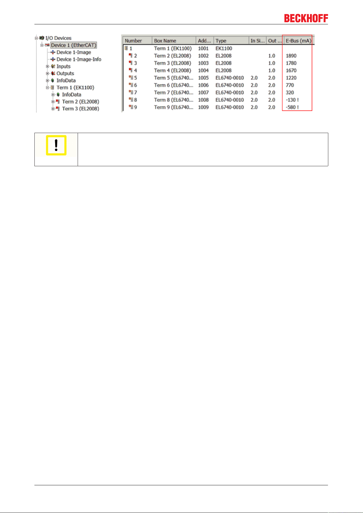
The settings of the SM- and PDI-watchdog must be done for each slave separately in the TwinCAT System
Manager.
EL70x728 Version 1.0
Page 29
Basics communication
Fig.18: EtherCAT tab -> Advanced Settings -> Behavior -> Watchdog
Notes:
• the multiplier is valid for both watchdogs.
• each watchdog has its own timer setting, the outcome of this in summary with the multiplier is a
resulting time.
• Important: the multiplier/timer setting is only loaded into the slave at the start up, if the checkbox is
activated.
If the checkbox is not activated, nothing is downloaded and the ESC settings remain unchanged.
Multiplier
Multiplier
Both watchdogs receive their pulses from the local terminal cycle, divided by the watchdog multiplier:
1/25 MHz * (watchdog multiplier + 2) = 100 µs (for default setting of 2498 for the multiplier)
The standard setting of 1000 for the SM watchdog corresponds to a release time of 100 ms.
The value in multiplier + 2 corresponds to the number of basic 40 ns ticks representing a watchdog tick.
The multiplier can be modified in order to adjust the watchdog time over a larger range.
EL70x7 29Version 1.0
Page 30
Basics communication
Example "Set SM watchdog"
This checkbox enables manual setting of the watchdog times. If the outputs are set and the EtherCAT
communication is interrupted, the SM watchdog is triggered after the set time and the outputs are erased.
This setting can be used for adapting a terminal to a slower EtherCAT master or long cycle times. The
default SM watchdog setting is 100 ms. The setting range is 0..65535. Together with a multiplier with a range
of 1..65535 this covers a watchdog period between 0..~170 seconds.
Calculation
Multiplier = 2498 → watchdog base time = 1 25 MHz * (2498 + 2) = 0.0001 seconds = 100 µs
SM watchdog = 10000 → 10000 * 100 µs = 1 second watchdog monitoring time
CAUTION! Undefined state possible!
The function for switching off of the SM watchdog via SM watchdog = 0 is only imple-
CAUTION
CAUTION
mented in terminals from version -0016. In previous versions this operating mode should
not be used.
CAUTION! Damage of devices and undefined state possible!
If the SM watchdog is activated and a value of 0 is entered the watchdog switches off completely. This is the deactivation of the watchdog! Set outputs are NOT set in a safe state, if
the communication is interrupted.
Outputs in SAFEOP state
The default set watchdog monitoring sets the outputs of the module in a safe state - de-
Note
pending on the settings in SAFEOP and OP - e.g. in OFF state. If this is prevented by deactivation of the watchdog monitoring in the module, the outputs can be switched or set
also in the SAFEOP state.
3.4 EtherCAT State Machine
The state of the EtherCAT slave is controlled via the EtherCAT State Machine (ESM). Depending upon the
state, different functions are accessible or executable in the EtherCAT slave. Specific commands must be
sent by the EtherCAT master to the device in each state, particularly during the bootup of the slave.
A distinction is made between the following states:
• Init
• Pre-Operational
• Safe-Operational and
• Operational
• Boot
The regular state of each EtherCAT slave after bootup is the OP state.
EL70x730 Version 1.0
Page 31

Fig.19: States of the EtherCAT State Machine
Basics communication
Init
After switch-on the EtherCAT slave in the Init state. No mailbox or process data communication is possible.
The EtherCAT master initializes sync manager channels 0 and 1 for mailbox communication.
Pre-Operational (Pre-Op)
During the transition between Init and Pre-Op the EtherCAT slave checks whether the mailbox was initialized
correctly.
In Pre-Op state mailbox communication is possible, but not process data communication. The EtherCAT
master initializes the sync manager channels for process data (from sync manager channel 2), the FMMU
channels and, if the slave supports configurable mapping, PDO mapping or the sync manager PDO
assignment. In this state the settings for the process data transfer and perhaps terminal-specific parameters
that may differ from the default settings are also transferred.
Safe-Operational (Safe-Op)
During transition between Pre-Op and Safe-Op the EtherCAT slave checks whether the sync manager
channels for process data communication and, if required, the distributed clocks settings are correct. Before
it acknowledges the change of state, the EtherCAT slave copies current input data into the associated DPRAM areas of the EtherCAT slave controller (ECSC).
In Safe-Op state mailbox and process data communication is possible, although the slave keeps its outputs
in a safe state, while the input data are updated cyclically.
Outputs in SAFEOP state
The default set watchdog monitoring sets the outputs of the module in a safe state - de-
Note
pending on the settings in SAFEOP and OP - e.g. in OFF state. If this is prevented by deactivation of the watchdog monitoring in the module, the outputs can be switched or set
also in the SAFEOP state.
Operational (Op)
Before the EtherCAT master switches the EtherCAT slave from Safe-Op to Op it must transfer valid output
data.
EL70x7 31Version 1.0
Page 32

Basics communication
In the Op state the slave copies the output data of the masters to its outputs. Process data and mailbox
communication is possible.
Boot
In the Boot state the slave firmware can be updated. The Boot state can only be reached via the Init state.
In the Boot state mailbox communication via the file access over EtherCAT (FoE) protocol is possible, but no
other mailbox communication and no process data communication.
3.5 CoE Interface
General description
The CoE interface (CANopen over EtherCAT) is used for parameter management of EtherCAT devices.
EtherCAT slaves or the EtherCAT master manage fixed (read only) or variable parameters which they
require for operation, diagnostics or commissioning.
CoE parameters are arranged in a table hierarchy. In principle, the user has read access via the fieldbus.
The EtherCAT master (TwinCAT System Manager) can access the local CoE lists of the slaves via
EtherCAT in read or write mode, depending on the attributes.
Different CoE parameter types are possible, including string (text), integer numbers, Boolean values or larger
byte fields. They can be used to describe a wide range of features. Examples of such parameters include
manufacturer ID, serial number, process data settings, device name, calibration values for analog
measurement or passwords.
The order is specified in 2 levels via hexadecimal numbering: (main)index, followed by subindex. The value
ranges are
• Index: 0...65535
• SubIndex: 0...255
A parameter localized in this way is normally written as x8010:07, with preceding "x" to identify the
hexadecimal numerical range and a colon between index and subindex.
The relevant ranges for EtherCAT fieldbus users are:
• x1000: This is where fixed identity information for the device is stored, including name, manufacturer,
serial number etc., plus information about the current and available process data configurations.
• x8000: This is where the operational and functional parameters for all channels are stored, such as
filter settings or output frequency.
Other important ranges are:
• x4000: In some EtherCAT devices the channel parameters are stored here (as an alternative to the
x8000 range).
• x6000: Input PDOs ("input" from the perspective of the EtherCAT master)
• x7000: Output PDOs ("output" from the perspective of the EtherCAT master)
Availability
Not every EtherCAT device must have a CoE list. Simple I/O modules without dedicated
Note
If a device has a CoE list, it is shown in the TwinCAT System Manager as a separate tab with a listing of the
elements:
processor usually have no variable parameters and therefore no CoE list..
EL70x732 Version 1.0
Page 33

Basics communication
Fig.20: "CoE Online " tab
The figure above shows the CoE objects available in device "EL2502", ranging from x1000 to x1600. The
subindices for x1018 are expanded.
Data management
Some parameters, particularly the setting parameters of the slave, are configurable and writeable. This can
be done in write or read mode
• via the System Manager (Fig. "CoE Online " tab) by clicking
This is useful for commissioning of the system/slaves. Click on the row of the index to be
parameterised and enter a value in the "SetValue" dialog.
• from the control system/PLC via ADS, e.g. through blocks from the TcEtherCAT.lib library
This is recommended for modifications while the system is running or if no System Manager or
operating staff are available.
If slave CoE parameters are modified online, Beckhoff devices store any changes in a fail-safe manner in the
EEPROM, i.e. the modified CoE parameters are still available after a restart. The situation may be different
with other manufacturers.
An EEPROM is subject to a limited lifetime with respect to write operations. From typically 100,000 write
operations onwards it can no longer be guaranteed that new (changed) data are reliably saved or are still
readable. This is irrelevant for normal commissioning. However, if CoE parameters are continuously changed
via ADS at machine runtime, it is quite possible for the lifetime limit to be reached. Support for the
NoCoeStorage function, which suppresses the saving of changed CoE values, depends on the firmware
version.
Data management
ü Data management function
Note
EL70x7 33Version 1.0
a) If the function is supported: the function is activated by entering the code word
0x12345678 once in CoE 0xF008 and remains active as long as the code word is not
changed. After switching the device on it is then inactive. Changed CoE values are not
saved in the EEPROM and can thus be changed any number of times.
b) Function is not supported: continuous changing of CoE values is not permissible in view
of the lifetime limit.
Page 34

Basics communication
Startup list
Changes in the local CoE list of the terminal are lost if the terminal is replaced. If a terminal
Note
is replaced with a new Beckhoff terminal, it will have the default settings. It is therefore advisable to link all changes in the CoE list of an EtherCAT slave with the Startup list of the
slave, which is processed whenever the EtherCAT fieldbus is started. In this way a replacement EtherCAT slave can automatically be parameterised with the specifications of the
user.
If EtherCAT slaves are used which are unable to store local CoE values permanently, the
Startup list must be used.
Recommended approach for manual modification of CoE parameters
• Make the required change in the System Manager
The values are stored locally in the EtherCAT slave
• If the value is to be stored permanently, enter it in the Startup list.
The order of the Startup entries is usually irrelevant.
Fig.21: Startup list in the TwinCAT System Manager
The Startup list may already contain values that were configured by the System Manager based on the ESI
specifications. Additional application-specific entries can be created.
Online/offline list
While working with the TwinCAT System Manager, a distinction has to be made whether the EtherCAT
device is "available", i.e. switched on and linked via EtherCAT and therefore online, or whether a
configuration is created offline without connected slaves.
In both cases a CoE list as shown in Fig. “’CoE online’ tab” is displayed. The connectivity is shown as offline/
online.
• If the slave is offline
- The offline list from the ESI file is displayed. In this case modifications are not meaningful or possible.
- The configured status is shown under Identity.
- No firmware or hardware version is displayed, since these are features of the physical device.
- Offline is shown in red.
EL70x734 Version 1.0
Page 35

Basics communication
Fig.22: Offline list
• If the slave is online
- The actual current slave list is read. This may take several seconds, depending on the size and cycle time.
- The actual identity is displayed
- The firmware and hardware version of the equipment according to the electronic information is displayed
- Online is shown in green.
Fig.23: Online list
Channel-based order
The CoE list is available in EtherCAT devices that usually feature several functionally equivalent channels.
For example, a 4-channel analog 0..10 V input terminal also has 4 logical channels and therefore 4 identical
sets of parameter data for the channels. In order to avoid having to list each channel in the documentation,
the placeholder "n" tends to be used for the individual channel numbers.
EL70x7 35Version 1.0
Page 36

Basics communication
In the CoE system 16 indices, each with 255 subindices, are generally sufficient for representing all channel
parameters. The channel-based order is therefore arranged in 16
dec
/10
steps. The parameter range x8000
hex
exemplifies this:
• Channel 0: parameter range x8000:00 ... x800F:255
• Channel 1: parameter range x8010:00 ... x801F:255
• Channel 2: parameter range x8020:00 ... x802F:255
• ...
This is generally written as x80n0.
Detailed information on the CoE interface can be found in the EtherCAT system documentation on the
Beckhoff website.
EL70x736 Version 1.0
Page 37

Basics communication
3.6 Distributed Clock
The distributed clock represents a local clock in the EtherCAT slave controller (ESC) with the following
characteristics:
• Unit 1 ns
• Zero point 1.1.2000 00:00
• Size 64 bit (sufficient for the next 584 years; however, some EtherCAT slaves only offer 32-bit support,
i.e. the variable overflows after approx. 4.2 seconds)
• The EtherCAT master automatically synchronizes the local clock with the master clock in the EtherCAT
bus with a precision of < 100 ns.
For detailed information please refer to the EtherCAT system description.
EL70x7 37Version 1.0
Page 38

Installation
4 Installation
4.1 Installation on mounting rails
Risk of electric shock and damage of device!
Bring the bus terminal system into a safe, powered down state before starting installation,
WARNING
Assembly
disassembly or wiring of the Bus Terminals!
Fig.24: Attaching on mounting rail
The Bus Coupler and Bus Terminals are attached to commercially available 35mm mounting rails (DIN rails
according to EN60715) by applying slight pressure:
1. First attach the Fieldbus Coupler to the mounting rail.
2. The Bus Terminals are now attached on the right-hand side of the Fieldbus Coupler. Join the
components with tongue and groove and push the terminals against the mounting rail, until the lock
clicks onto the mounting rail.
If the Terminals are clipped onto the mounting rail first and then pushed together without tongue and
groove, the connection will not be operational! When correctly assembled, no significant gap should
be visible between the housings.
Fixing of mounting rails
The locking mechanism of the terminals and couplers extends to the profile of the mounting
Note
rail. At the installation, the locking mechanism of the components must not come into conflict with the fixing bolts of the mounting rail. To mount the mounting rails with a height of
7.5mm under the terminals and couplers, you should use flat mounting connections (e.g.
countersunk screws or blind rivets).
EL70x738 Version 1.0
Page 39

Disassembly
Fig.25: Disassembling of terminal
Each terminal is secured by a lock on the mounting rail, which must be released for disassembly:
Installation
1. Pull the terminal by its orange-colored lugs approximately 1cm away from the mounting rail. In doing
so for this terminal the mounting rail lock is released automatically and you can pull the terminal out of
the bus terminal block easily without excessive force.
2. Grasp the released terminal with thumb and index finger simultaneous at the upper and lower grooved
housing surfaces and pull the terminal out of the bus terminal block.
Connections within a bus terminal block
The electric connections between the Bus Coupler and the Bus Terminals are automatically realized by
joining the components:
• The six spring contacts of the K-Bus/E-Bus deal with the transfer of the data and the supply of the Bus
Terminal electronics.
• The power contacts deal with the supply for the field electronics and thus represent a supply rail within
the bus terminal block. The power contacts are supplied via terminals on the Bus Coupler (up to 24V)
or for higher voltages via power feed terminals.
Power Contacts
During the design of a bus terminal block, the pin assignment of the individual Bus Termi-
Note
nals must be taken account of, since some types (e.g. analog Bus Terminals or digital 4channel Bus Terminals) do not or not fully loop through the power contacts. Power Feed
Terminals (KL91xx, KL92xx or EL91xx, EL92xx) interrupt the power contacts and thus represent the start of a new supply rail.
PE power contact
The power contact labeled PE can be used as a protective earth. For safety reasons this contact mates first
when plugging together, and can ground short-circuit currents of up to 125A.
EL70x7 39Version 1.0
Page 40

Installation
Fig.26: Power contact on left side
Attention
WARNING
Possible damage of the device
Note that, for reasons of electromagnetic compatibility, the PE contacts are capacitatively
coupled to the mounting rail. This may lead to incorrect results during insulation testing or
to damage on the terminal (e.g. disruptive discharge to the PE line during insulation testing
of a consumer with a nominal voltage of 230V). For insulation testing, disconnect the PE
supply line at the Bus Coupler or the Power Feed Terminal! In order to decouple further
feed points for testing, these Power Feed Terminals can be released and pulled at least
10mm from the group of terminals.
Risk of electric shock!
The PE power contact must not be used for other potentials!
EL70x740 Version 1.0
Page 41

Installation
4.2 Connection system
Risk of electric shock and damage of device!
Bring the bus terminal system into a safe, powered down state before starting installation,
WARNING
Overview
The Bus Terminal system offers different connection options for optimum adaptation to the respective
application:
• The terminals of KLxxxx and ELxxxx series with standard wiring include electronics and connection
level in a single enclosure.
• The terminals of KSxxxx and ESxxxx series feature a pluggable connection level and enable steady
wiring while replacing.
• The High Density Terminals (HD Terminals) include electronics and connection level in a single
enclosure and have advanced packaging density.
Standard wiring
disassembly or wiring of the Bus Terminals!
Fig.27: Standard wiring
The terminals of KLxxxx and ELxxxx series have been tried and tested for years.
They feature integrated screwless spring force technology for fast and simple assembly.
Pluggable wiring
Fig.28: Pluggable wiring
The terminals of KSxxxx and ESxxxx series feature a pluggable connection level.
The assembly and wiring procedure for the KS series is the same as for the KLxxxx and ELxxxx series.
The KS/ES series terminals enable the complete wiring to be removed as a plug connector from the top of
the housing for servicing.
The lower section can be removed from the terminal block by pulling the unlocking tab.
Insert the new component and plug in the connector with the wiring. This reduces the installation time and
eliminates the risk of wires being mixed up.
The familiar dimensions of the terminal only had to be changed slightly. The new connector adds about 3
mm. The maximum height of the terminal remains unchanged.
A tab for strain relief of the cable simplifies assembly in many applications and prevents tangling of individual
connection wires when the connector is removed.
EL70x7 41Version 1.0
Page 42
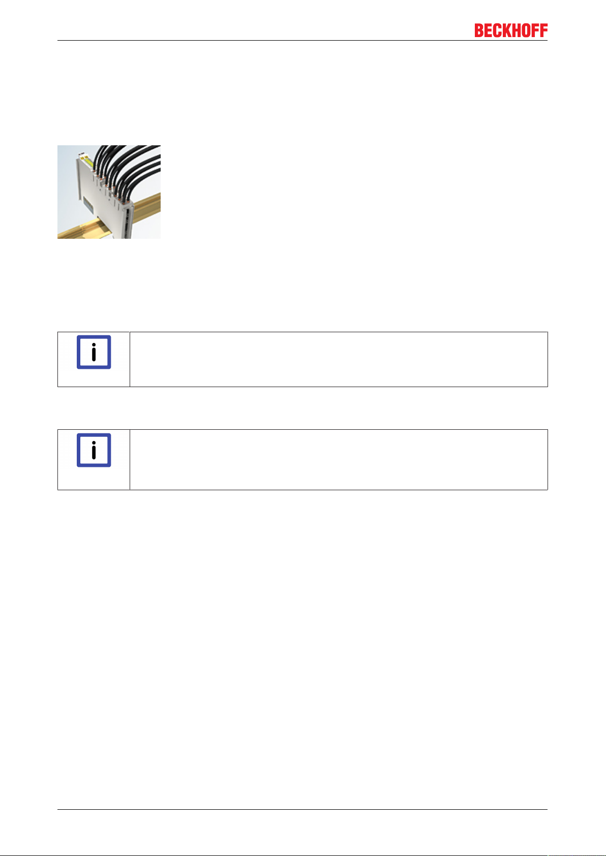
Installation
Conductor cross sections between 0.08mm2 and 2.5mm2 can continue to be used with the proven spring
force technology.
The overview and nomenclature of the product names for KSxxxx and ESxxxx series has been retained as
known from KLxxxx and ELxxxx series.
High Density Terminals (HD Terminals)
Fig.29: High Density Terminals
The Bus Terminals from these series with 16 connection points are distinguished by a particularly compact
design, as the packaging density is twice as large as that of the standard 12mm Bus Terminals. Massive
conductors and conductors with a wire end sleeve can be inserted directly into the spring loaded terminal
point without tools.
Wiring HD Terminals
The High Density (HD) Terminals of the KLx8xx and ELx8xx series doesn't support steady
Note
wiring.
Ultrasonically "bonded" (ultrasonically welded) conductors
Ultrasonically “bonded" conductors
It is also possible to connect the Standard and High Density Terminals with ultrasonically
Note
"bonded" (ultrasonically welded) conductors. In this case, please note the tables concerning the wire-size width [}43] below!
EL70x742 Version 1.0
Page 43
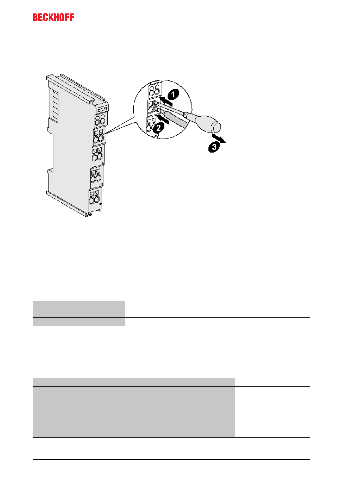
Installation
Wiring
Terminals for standard wiring ELxxxx / KLxxxx and terminals for steady wiring
ESxxxx / KSxxxx
Fig.30: Mounting a cable on a terminal connection
Up to eight connections enable the connection of solid or finely stranded cables to the Bus Terminals. The
terminals are implemented in spring force technology. Connect the cables as follows:
1. Open a spring-loaded terminal by slightly pushing with a screwdriver or a rod into the square opening
above the terminal.
2. The wire can now be inserted into the round terminal opening without any force.
3. The terminal closes automatically when the pressure is released, holding the wire securely and
permanently.
Terminal housing ELxxxx, KLxxxx ESxxxx, KSxxxx
Wire size width 0.08 ... 2,5mm
2
0.08 ... 2.5mm
2
Wire stripping length 8 ... 9mm 9 ... 10mm
High Density Terminals ELx8xx, KLx8xx (HD)
The conductors of the HD Terminals are connected without tools for single-wire conductors using the direct
plug-in technique, i.e. after stripping the wire is simply plugged into the contact point. The cables are
released, as usual, using the contact release with the aid of a screwdriver. See the following table for the
suitable wire size width.
Terminal housing High Density Housing
Wire size width (conductors with a wire end sleeve) 0.14... 0.75mm
Wire size width (single core wires) 0.08 ... 1.5mm
Wire size width (fine-wire conductors) 0.25 ... 1.5mm
Wire size width (ultrasonically “bonded" conductors)
only 1.5mm2 (see notice
[}42]!)
Wire stripping length 8 ... 9mm
2
2
2
EL70x7 43Version 1.0
Page 44

Installation
Shielding
Note
Shielding
Analog sensors and actors should always be connected with shielded, twisted paired wires.
EL70x744 Version 1.0
Page 45

Installation
4.3 Installation position
Constraints regarding installation position and operating temperature range
When installing the terminals ensure that an adequate spacing is maintained between other
Attention
Prescribed installation position
The prescribed installation position requires the mounting rail to be installed horizontally and the connection
surfaces of the EL/KL terminals to face forward (see Fig. 1).
The terminals are ventilated from below, which enables optimum cooling of the electronics through
convection. "From below" is relative to the acceleration of gravity.
components above and below the terminal in order to guarantee adequate ventilation!
Fig. 1: Recommended distances for standard installation position
Compliance with the distances shown in Fig. 1 is strongly recommended.
EL70x7 45Version 1.0
Page 46
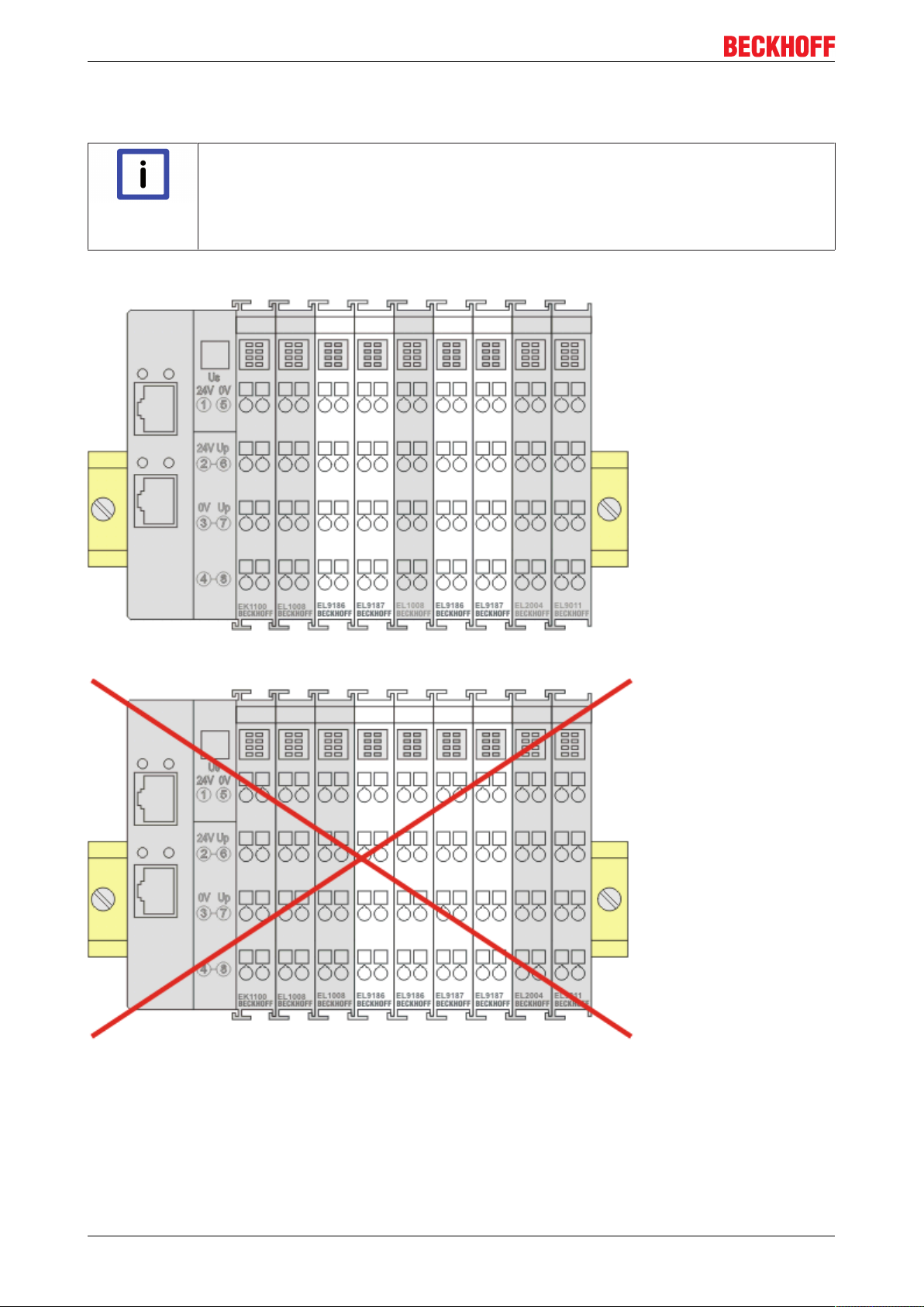
Installation
4.4 Mounting of Passive Terminals
Hint for mounting passive terminals
EtherCAT Bus Terminals (ELxxxx / ESxxxx), which do not take an active part in data trans-
Note
Examples for mounting passive terminals (highlighted)
fer within the bus terminal block are so called Passive Terminals. The Passive Terminals
have no current consumption out of the E-Bus To ensure an optimal data transfer, you
must not directly string together more than 2 Passive Terminals!
Fig.31: Correct configuration
Fig.32: Incorrect configuration
EL70x746 Version 1.0
Page 47

Installation
4.5 Shielding concept
Together with the shield busbar, the prefabricated cables from Beckhoff Automation offer optimum protection
against electromagnetic interference.
Connection of the motor cable to the shield busbar
Fasten the shield busbar supports 1 to the DIN rail 2. The DIN rail 2 must be in contact with the metallic rear
wall of the control cabinet over a wide area. Install the shield busbar 3 as shown below.
Fig.33: Shield busbar
Connect the cores 4 of the motor cable 5, and then attach the copper-sheathed end 6 of the motor cable 5
with the shield clamp 7 to the shield busbar 3. Tighten the screw 8 to the stop.
Fasten the PE clamp 9 to the shield busbar 3. Clamp the PE core 10 of the motor cable 5 under the PE
clamp 9.
Fig.34: Screen connection
Connection of the feedback cable
The shield of the feedback cable is connected via the metallic plug fastener when screwing the feedback
plug onto the AM3100.
On the terminal side the shield can also be connected.. Connect the cores of the feedback cable and attach
the copper-sheathed end of the feedback cable to the shield busbar 3 with the shield clamp 7. The motor
cable and the feedback cable can be connected to the shield clamp 7 with the screw 8.
EL70x7 47Version 1.0
Page 48

Installation
4.6 EL7037
4.6.1 EL7037 - LEDs and connection
WARNING! Risk of electric shock and damage of devices possible!
Bring the bus terminal system into a safe, powered down state before starting installation,
WARNING
disassembly or wiring of the Bus Terminals!
EL70x748 Version 1.0
Page 49

Installation
EL7037-0000
LEDs
No. LED Color Meaning
1 RUN green This LED indicates the terminal's operating state:
off State of the EtherCAT State Machine: INIT =
Initialization of the terminal or BOOTSTRAP =
Function for firmware updates of the terminal
blinking State of the EtherCAT State Machine: PREOP =
Setting for mailbox communication and variant
standard settings
single flash State of the EtherCAT State Machine: SAFEOP =
Channel checking of the Sync Manager and the
Distributed Clocks. Outputs stay in safe operation
mode.
on State of the EtherCAT State Machine: OP = Normal
operation mode, mailbox- and process data
communication possible
2 Encoder green on Encoder ready for operation
3 A green on Signal at encoder input A
4 B green on Signal at encoder input B
5 C green on Signal at encoder input C
6 Latch green on Signal at latch input
7 Turn CW green on Motor is triggered clock wise
8 Input 1 green on Signal at digital input 1
9 Driver green on Driver stage ready for operation
10 Power green off The power supply voltage (24 VDC) is absent or
the motor control is blocked (Index 6010:02 [}185] is
not set))
on The power supply voltage (24 VDC) is present
11 Warning yellow on Configuration error, e.g.:
• Motor power supply not connected
• 80°C temperature exceeded
• 100% duty cycle reached
• ...
12 Error A red on Configuration error of output stage A, e.g.:
• 100°C temperature exceeded
• short circuit
• ...
13 Error B red on Configuration error of output stage B, e.g.:
• 100°C temperature exceeded
• short circuit
• ...
14 Enable green off
on
15 Turn CCW green on Motor is triggered counter clock wise
16 Input 2 green on Signal at digital input 2
The motor control is blocked (Index 6010:02 [}185] is
not set) or EL7037 is not ready for operation
The motor control is activated (Index 6010:02 [}185]
is set) or EL7037 is ready for operation
EL70x7 49Version 1.0
Page 50

Installation
Terminal points
Terminal
point
1 A Encoder input A
2 C
3 Encoder supply
4 A1 Motor winding A1
5 B1 Motor winding B1
6 +24V +24 VDC, internally connected with positive power contact and
7 +24V +24 VDC, internally connected with positive power contact and
8 Input 1 Digital input 1 (24 VDC)
9 B Encoder input B
10 Latch Latch input. The current counter value is stored as a
11 Encoder supply
12 A2 Motor winding A2
13 B2 Motor winding B2
14 0V 0 VDC, internally connected with negative power contact and
15 0V 0 VDC, internally connected with negative power contact and
16 Input 2 Digital input 2 (24 VDC), also configurable as a digital output
Name Signal
Encoder input C (zero input). If object 7000:01 [}186] is set in
the control word and a rising edge occurs at encoder input C,
the current counter value is stored as a reference mark in the
latch register.
Encoder supply + 24 V, internally connected with positive
+24V
0V
power contact and pin 6, 7
pin 3, 7
pin 3, 7
reference mark in the latch register, if
• object 7000:02 [}186] is set and a rising edge occurs at
• object 7000:04 [}186] is set and a falling edge occurs
Encoder supply 0 V, internally connected with negative power
contact and pin 14, 15
pin 11, 15
pin 11, 14
(0,5 A)
the latch input; or
at the latch input.
4.6.2 EL7037 - General connection examples
Risk of injury through electric shock and damage to the device!
Bring the Bus Terminal system into a safe, de-energized state before starting mounting,
WARNING
Attention
disassembly or wiring of the Bus Terminals.
Connect the motor strands correctly!
Connect the windings of a motor strand only to the terminal points of the same output driver
of the stepper motor terminal, e.g.:
• one motor strand to terminal points A1 and A2,
• the other motor strand to terminal points B1 and B2.
Connecting a motor strand to the terminal points of different output drivers (e.g. to A1 and
B1) can lead to destruction of the output drivers of stepper motor terminal!
EL70x750 Version 1.0
Page 51

Installation
Connection types
The EL7047 Stepper Motor terminal has bipolar output stages and can control bipolar and unipolar motors.
Bipolar motors
Fig.35: Bipolar control (serial) of a bipolar motor
Fig.36: Bipolar control (parallel) of a bipolar motor
Documentation for stepper motors from Beckhoff
These two examples show the connection of the bipolar Beckhoff motors AS1010, AS1020,
Note
AS1030, AS1050 or AS1060. Further information on stepper motors from Beckhoff can be
found in the associated documentation available for download from our website at http://
www.beckhoff.com.
EL70x7 51Version 1.0
Page 52

Installation
Fig.37: Bipolar control of a unipolar motor
Only one half of each winding is controlled.
EL70x752 Version 1.0
Page 53

4.7 EL7047
4.7.1 EL7047 - LEDs and connection
WARNING! Risk of electric shock and damage of devices possible!
Bring the bus terminal system into a safe, powered down state before starting installation,
disassembly or wiring of the Bus Terminals!
WARNING
EL7047-0000
Installation
Fig.38: LEDs and Connection EL7047
EL70x7 53Version 1.0
Page 54

Installation
LEDs (left prism)
LED Color Meaning
RUN green This LED indicates the terminal's operating state:
off State of the EtherCAT State Machine: INIT = Initialization of the
terminal or BOOTSTRAP = Function for firmware updates of the
terminal
blinking State of the EtherCAT State Machine: PREOP = Setting for mailbox
communication and variant standard settings
single flash State of the EtherCAT State Machine: SAFEOP = Channel checking of
the Sync Manager and the Distributed Clocks. Outputs stay in safe
operation mode.
on State of the EtherCAT State Machine: OP = Normal operation mode,
mailbox- and process data communication possible
Encoder green on Encoder ready for operation
A green on Signal at encoder input A
B green on Signal at encoder input B
C green on Signal at encoder input C
Latch green on Signal at latch input
Input 1 green on Signal at digital input 1
Input 2 green on Signal at digital input 2
LEDs (right prism)
LED Color Meaning
Driver green on Driver stage ready for operation
Power green off The power supply voltage (50 VDC) is absent or
the motor control is blocked (Index 6010:02 [}185] is not set))
on The power supply voltage (50 VDC) is present
Turn CW green on Motor is triggered clock wise
Turn CCW green on Motor is triggered counter clock wise
Enable green off
on
Warning yellow off No errors
on Configuration error, e.g.:
Error A red on Configuration error of output stage A, e.g.:
Error B red on Configuration error of output stage B, e.g.:
The motor control is blocked (Index 6010:02 [}185] is not set) or
EL7047 is not ready for operation
The motor control is activated (Index 6010:02 [}185] is set) or EL7047
is ready for operation
• Motor power supply not connected
• 80°C temperature exceeded
• 100% duty cycle reached
• ...
• 100°C temperature exceeded
• short circuit
• ...
• 100°C temperature exceeded
• short circuit
• ...
EL70x754 Version 1.0
Page 55

Terminal Points - Left-hand section of the housing
Installation
Terminal
point
1 A Encoder input A
2 C
3 Encoder supply
4 Input 1 Digital input 1 (24 VDC)
5 B Encoder input B
6 Latch / Gate Latch input. The current counter value is stored as a reference mark in
7 Encoder supply
8 Input 2 Digital input 2 (24 VDC)
Name Signal
Encoder input C (zero input). If object 7000:01 [}186] is set in the
control word and a rising edge occurs at encoder input C, the current
counter value is stored as a reference mark in the latch register.
Encoder supply (from positive power contact)
+24V
the latch register, if
• object 7000:02 [}186] is set and a rising edge occurs at the latch
input; or
• object 7000:04 [}186] is set and a falling edge occurs at the latch
input.
Encoder supply (from negative power contact)
0V
Terminal Points - Right-hand section of the housing
Terminal
point
1' A1 Motor winding A1
2' B1 Motor winding B1
3' Motor supply +50V Feeding for output stage (max. +50 VDC)
4' Motor supply +50V Feeding for output stage (max. +50 VDC)
5' A2 Motor winding A2
6' B2 Motor winding B2
7' Motor supply 0V Feeding for output stage (0 VDC)
8' Motor supply 0V Feeding for output stage (0 VDC)
Name Signal
4.7.2 EL7047 - General connection examples
Risk of injury through electric shock and damage to the device!
Bring the Bus Terminal system into a safe, de-energized state before starting mounting,
WARNING
Attention
disassembly or wiring of the Bus Terminals.
Connect the motor strands correctly!
Connect the windings of a motor strand only to the terminal points of the same output driver
of the stepper motor terminal, e.g.:
• one motor strand to terminal points A1 and A2,
• the other motor strand to terminal points B1 and B2.
Connecting a motor strand to the terminal points of different output drivers (e.g. to A1 and
B1) can lead to destruction of the output drivers of stepper motor terminal!
EL70x7 55Version 1.0
Page 56

Installation
Use a brake chopper terminal (EL9576) for short deceleration ramps!
Very short deceleration ramps may lead to temporarily increased feedback. In this case the
Attention
terminal would report an error. In order to avoid this, a brake chopper terminal (EL9576)
should be connected in parallel to the power supply for the motor so that any energy being
fed back is absorbed.
Connection types
The EL7047 Stepper Motor terminal has bipolar output stages and can control bipolar and unipolar motors.
Bipolar motors
Fig.39: Bipolar control (serial) of a bipolar motor
Fig.40: Bipolar control (parallel) of a bipolar motor
Documentation for stepper motors from Beckhoff
These two examples show the connection of the bipolar Beckhoff motors AS1010, AS1020,
Note
AS1030, AS1050 or AS1060. Further information on stepper motors from Beckhoff can be
found in the associated documentation available for download from our website at http://
www.beckhoff.com.
EL70x756 Version 1.0
Page 57

Unipolar motors
Bipolar control of a unipolar motor
Installation
Fig.41: Bipolar control with only one half of each winding is controlled
Encoder
Connecting an encoder (24 V)
Fig.42: The encoder is supplied from the power contacts via terminal points 3 (+24 V) and 7 (0 V).
EL70x7 57Version 1.0
Page 58
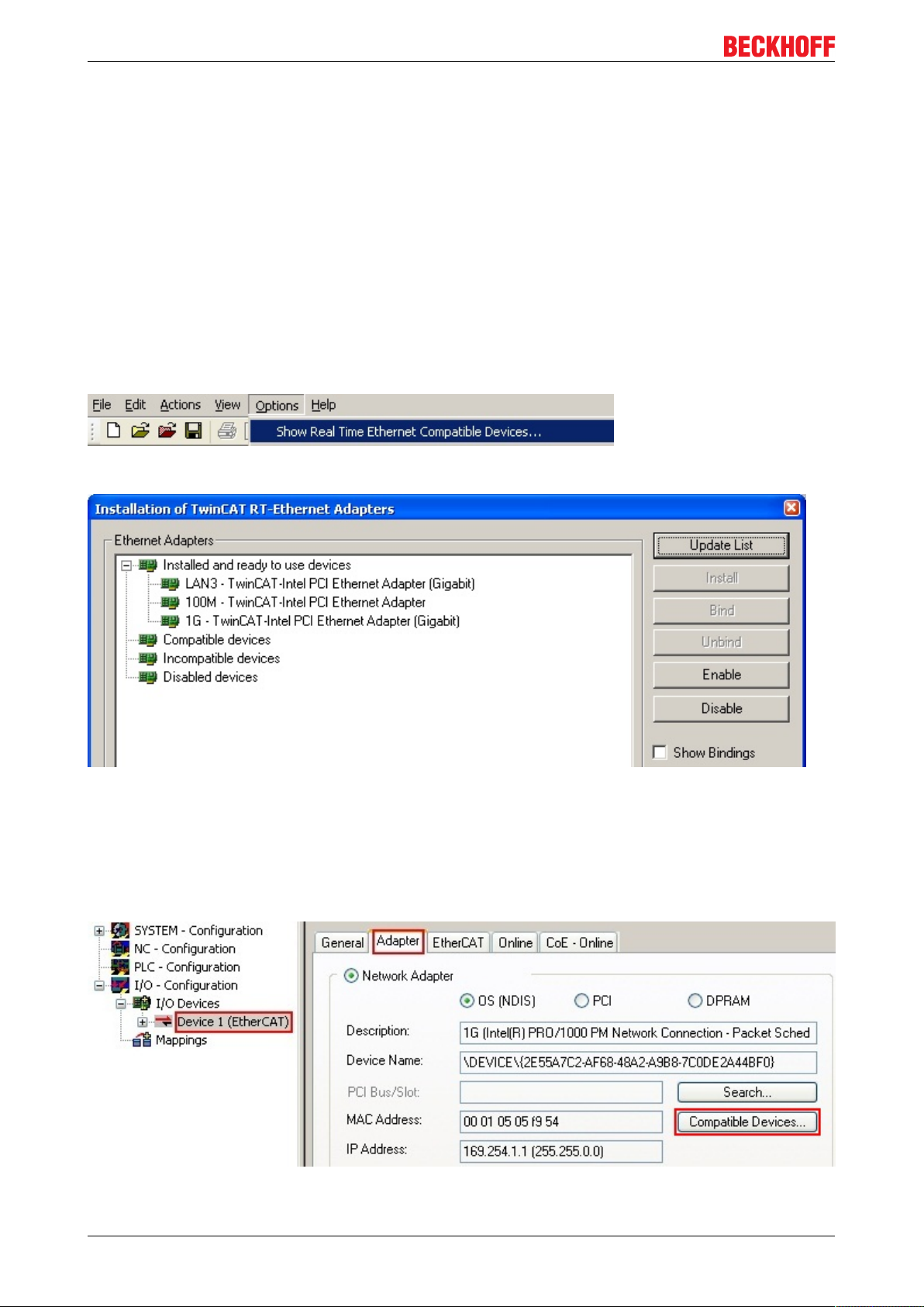
Commissioning
5 Commissioning
5.1 TwinCAT 2.1x
5.1.1 Installation of the TwinCAT real-time driver
In order to assign real-time capability to a standard Ethernet port of an IPC controller, the Beckhoff real-time
driver has to be installed on this port under Windows.
This can be done in several ways. One option is described here.
In the System Manager call up the TwinCAT overview of the local network interfaces via Options -> Show
Real Time Ethernet Compatible Devices.
Fig.43: System Manager option
Fig.44: Overview of network interfaces
Interfaces listed under “Compatible devices” can be assigned a driver via the “Install” button. A driver should
only be installed on compatible devices.
A Windows warning regarding the unsigned driver can be ignored.
Alternatively, the compatible Ethernet ports can be viewed in the System Manager via EtherCAT properties.
Fig.45: EtherCAT device properties
EL70x758 Version 1.0
Page 59

Commissioning
After the installation the driver appears activated in the Windows overview for the network interface
(Windows Start -->System Properties -> Network)
Fig.46: Windows properties of the network interface
Other possible settings are to be avoided:
EL70x7 59Version 1.0
Page 60
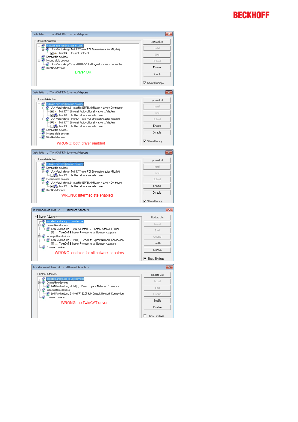
Commissioning
Fig.47: Incorrect driver settings for the Ethernet port
EL70x760 Version 1.0
Page 61
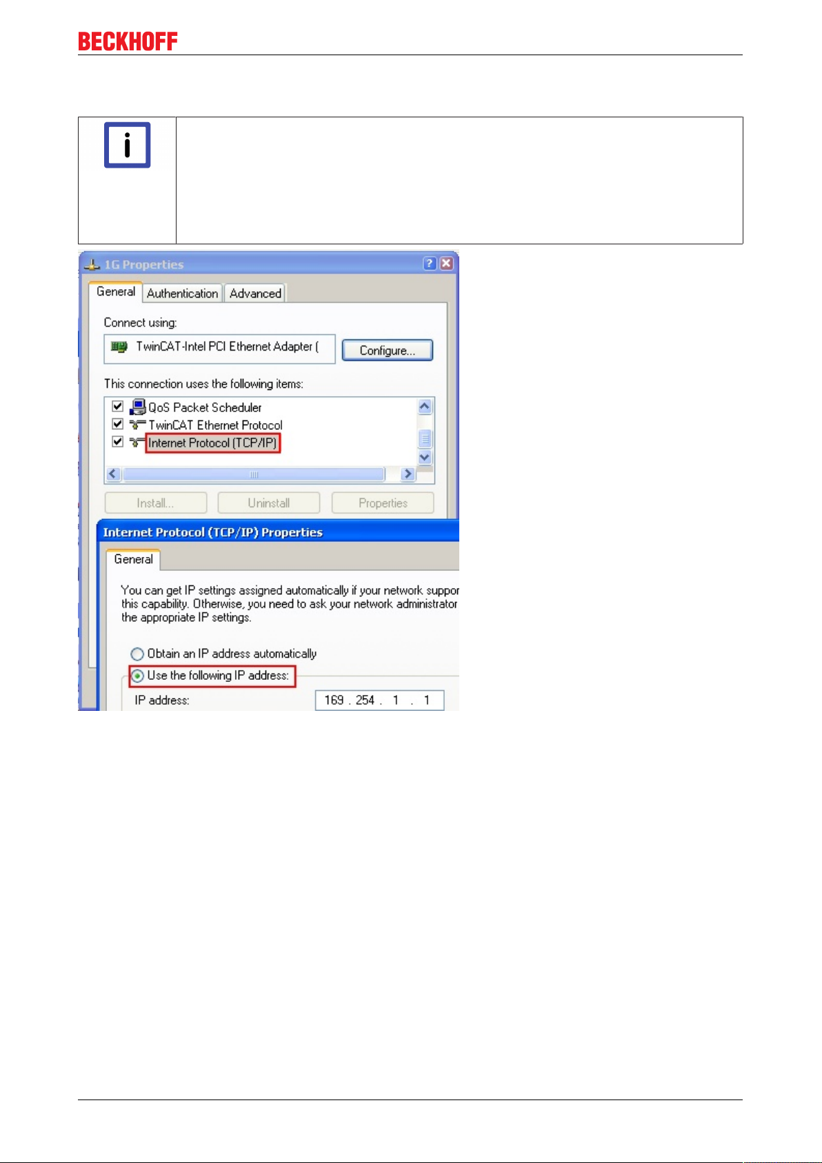
IP address of the port used
IP address/DHCP
In most cases an Ethernet port that is configured as an EtherCAT device will not transport
Note
general IP packets. For this reason and in cases where an EL6601 or similar devices are
used it is useful to specify a fixed IP address for this port via the “Internet Protocol TCP/IP”
driver setting and to disable DHCP. In this way the delay associated with the DHCP client
for the Ethernet port assigning itself a default IP address in the absence of a DHCP server
is avoided. A suitable address space is 192.168.x.x, for example.
Commissioning
Fig.48: TCP/IP setting for the Ethernet port
EL70x7 61Version 1.0
Page 62

Commissioning
5.1.2 Notes regarding ESI device description
Installation of the latest ESI device description
The TwinCAT EtherCAT master/System Manager needs the device description files for the devices to be
used in order to generate the configuration in online or offline mode. The device descriptions are contained
in the so-called ESI files (EtherCAT Slave Information) in XML format. These files can be requested from the
respective manufacturer and are made available for download. An *.xml file may contain several device
descriptions.
The ESI files for Beckhoff EtherCAT devices are available on the Beckhoff website.
The ESI files should be stored in the TwinCAT installation directory (default TwinCAT2: C:\TwinCAT\IO
\EtherCAT). The files are read (once) when a new System Manager window is opened, if they have changed
since the last time the System Manager window was opened.
A TwinCAT installation includes the set of Beckhoff ESI files that was current at the time when the TwinCAT
build was created.
For TwinCAT 2.11/TwinCAT 3 and higher, the ESI directory can be updated from the System Manager, if the
programming PC is connected to the Internet (Option -> “Update EtherCAT Device Descriptions”)
Fig.49: For TwinCAT 2.11 and higher, the System Manager can search for current Beckhoff ESI files automatically, if an online connection is available
ESI
The *.xml files are associated with *.xsd files, which describe the structure of the ESI XML
Note
files. To update the ESI device descriptions, both file types should therefore be updated.
Device differentiation
EtherCAT devices/slaves are distinguished by 4 properties, which determine the full device identifier. The
EL2521-0025-1018 ID consists of
• family key “EL”
• name “2521”
• type “0025”
• and revision “1018”
Fig.50: Identifier structure
The order identifier consisting of name + type (here: EL2521-0010) describes the device function. The
revision indicates the technical progress and is managed by Beckhoff. In principle, a device with a higher
revision can replace a device with a lower revision, unless specified otherwise, e.g. in the documentation.
Each revision has its own ESI description. See further notes [}8].
Online description
If the EtherCAT configuration is created online through scanning of real devices (see section Online setup)
and no ESI descriptions are available for a slave (specified by name and revision) that was found, the
System Manager asks whether the description stored in the device should be used. In any case, the System
Manager needs this information for setting up the cyclic and acyclic communication with the slave correctly.
EL70x762 Version 1.0
Page 63

Fig.51: OnlineDescription information window
In TwinCAT 3.x a similar window appears, which also offers the Web update:
Commissioning
Fig.52: Information window OnlineDescription, TwinCAT 3.x
If possible, the Yes is to be rejected and the required ESI is to be requested from the device manufacturer.
After installation of the XML/XSD file the configuration process should be repeated.
Changing the ‘usual’ configuration through a scan
ü If a scan discovers a device that is not yet known to TwinCAT, distinction has to be
Attention
Refer in particular to the chapter ‘General notes on the use of Beckhoff EtherCAT IO components’ and for
manual configuration to the chapter ‘Configuration creation – manual’
If the OnlineDescription is used regardless, the System Manager reads a copy of the device description from
the EEPROM in the EtherCAT slave. In complex slaves the size of the EEPROM may not be sufficient for the
complete ESI, in which case the ESI would be incomplete in the configurator. The route via the ESI files is
therefore recommended.
made between two cases. Taking the example here of the EL2521-0000 in the revision
1019
a) no ESI is present for the EL2521-0000 device at all, either for the revision 1019 or for
an older revision. The ESI must then be requested from the manufacturer (in this case
Beckhoff).
b) an ESI is present for the EL2521-0000 device, but only in an older revision, e.g. 1018 or
1017.
In this case an in-house check should first be performed to determine whether the
spare parts stock allows the integration of the increased revision into the configuration
at all. A new/higher revision usually also brings along new features. If these are not to
be used, work can continue without reservations with the previous revision 1018 in the
configuration. This is also stated by the Beckhoff compatibility rule.
The System Manager creates a new file “OnlineDescription0000...xml” its ESI directory, which contains all
ESI descriptions that were read online.
Fig.53: File OnlineDescription.xml created by the System Manager
EL70x7 63Version 1.0
Page 64

Commissioning
If slaves are added manually to the configuration at a later stage, slaves created in the manner described
above are indicated by an arrow, see Fig. “Arrow indicates ESI recorded from OnlineDescription”, EL2521.
Fig.54: Arrow indicates ESI recorded from OnlineDescription
If such ESI files are used and the manufacturer's files become available later, the file OnlineDescription.xml
should be deleted as follows:
• close all System Manager windows
• restart TwinCAT in Config mode
• delete "OnlineDescription0000...xml"
• restart TwinCAt System Manager
This file should not be visible after this procedure, if necessary press <F5> to update
OnlineDescription for TwinCAT 3.x
In addition to the file described above "OnlineDescription0000...xml" , a so called EtherCAT
Note
cache with new discovered devices is created by TwinCAT 3.x (e.g. under Windows 7)C:
\User\[USERNAME]\AppData\Roaming\Beckhoff\TwinCAT3\Components\Base\EtherCATCache.xml (Please note the language settings of the OS!)You have to delete this file, too.
Faulty ESI file
If an ESI file is faulty and the System Manager is unable to read it, the System Manager brings up an
information window.
Fig.55: Information window for faulty ESI file
Reasons may include:
EL70x764 Version 1.0
Page 65

Commissioning
• Structure of the *.xml does not correspond to the associated *.xsd file --> check your schematics
• Contents cannot be translated into a device description --> contact the file manufacturer
EL70x7 65Version 1.0
Page 66

Commissioning
5.1.3 Offline configuration creation (master: TwinCAT 2.x)
Distinction between Online and Offline
The distinction between online and offline refers to the presence of the actual I/O environment (drives,
terminals). If the configuration is to be prepared in advance of the system configuration as a programming
system, e.g. on a laptop, this is only possible in “Offline configuration” mode. In this case all components
have to be entered manually in the configuration, e.g. based on the electrical design.
If the designed control system is already connected to the EtherCAT system and all components are
energised and the infrastructure is ready for operation, the TwinCAT configuration can simply be generated
through “scanning” from the runtime system. This is referred to as online configuration.
In any case, during each startup the EtherCAT master checks whether the slaves it finds match the
configuration. This test can be parameterised in the extended slave settings.
Installation of the latest ESI-XML device description
The TwinCAT EtherCAT master/System Manager needs the device description files for the
Note
devices to be used in order to generate the configuration in online or offline mode. The device descriptions are contained in the so-called ESI files (EtherCAT Slave Information) in
XML format. These files can be requested from the respective manufacturer and are made
available for download. The ESIs for Beckhoff EtherCAT devices are provided on the Beck-
hoff website. The ESI files should be saved in the TwinCAT installation directory (default:
C:\TwinCAT\IO\EtherCAT ). The files are read (once) when a new System Manager window is opened.A TwinCAT installation includes the set of Beckhoff ESI files that was current at the time when the TwinCAT build was created.
For TwinCAT 2.11 and higher, the ESI directory can be updated from the System Manager, if the
programming PC is connected to the Internet (Option -> “Update EtherCAT Device Descriptions”)
Fig.56: Updating of the ESI directory
The following conditions must be met before a configuration can be set up:
• the EtherCAT device must be created/defined in the System Manager [}66]
• the EtherCAT slaves must be defined [}68]
Creating the EtherCAT device
Create an EtherCAT device in an empty System Manager window.
Fig.57: Append EtherCAT device
Select type ‘EtherCAT’ for an EtherCAT I/O application with EtherCAT slaves. For the present publisher/
subscriber service in combination with an EL6601/EL6614 terminal select “EtherCAT Automation Protocol
via EL6601”.
EL70x766 Version 1.0
Page 67

Fig.58: Selecting the EtherCAT connection (TwinCAT 2.11)
Commissioning
Fig.59: Selecting the EtherCAT connection (TwinCAT 2.11 R2)
Then assign a real Ethernet port to this virtual device in the runtime system.
Fig.60: Selecting the Ethernet port
This query may appear automatically when the EtherCAT device is created, or the assignment can be set/
modified later in the properties dialog (see Fig. “EtherCAT properties dialog”).
EL70x7 67Version 1.0
Page 68

Commissioning
Fig.61: EtherCAT properties dialog
Selecting the Ethernet port
Ethernet ports can only be selected for EtherCAT devices for which the TwinCAT real-time
Note
driver is installed. This has to be done separately for each port. Please refer to the respective installation page.
Defining EtherCAT slaves
Further devices can be appended by right-clicking on a device in the configuration tree.
Fig.62: Appending EtherCAT devices
The dialog for selecting a new device opens. Only devices for which ESI files are available are displayed.
Only devices are offered for selection that can be appended to the previously selected device. Therefore the
physical layer available for this port is also displayed (Fig. “Selection dialog for new EtherCAT device”, A). In
the case of cable-based Fast-Ethernet physical layer with PHY transfer, then also only cable-based devices
are available, as shown in Fig. “Selection dialog for new EtherCAT device”. If the preceding device has
several free ports (e.g. EK1122 or EK1100), the required port can be selected on the right-hand side (A).
Overview of physical layer
• “Ethernet”: cable-based 100BASE-TX: EK couplers, EP boxes, devices with RJ45/M8/M12 connector
• “E-Bus”: LVDS “terminal bus”: EL/ES terminals, various modular modules
The search field facilitates finding specific devices (TwinCAT 2.11 or higher).
EL70x768 Version 1.0
Page 69

Commissioning
Fig.63: Selection dialog for new EtherCAT device
By default only the name/device type is used as selection criterion. For selecting a specific revision of the
device the revision can be displayed as “Extended Information”.
Fig.64: Display of device revision
In many cases several device revisions were created for historic or functional reasons, e.g. through
technological advancement. For simplification purposes (see Fig. “Selection dialog for new EtherCAT
device”) only the last (i.e. highest) revision and therefore the latest state of production is displayed in the
selection dialog for Beckhoff devices. To show all device revisions available in the system as ESI
descriptions tick the “Show Hidden Devices” check box, see Fig. “Display of previous revisions”.
EL70x7 69Version 1.0
Page 70

Commissioning
Fig.65: Display of previous revisions
Device selection based on revision, compatibility
The ESI description also defines the process image, the communication type between mas-
Note
ter and slave/device and the device functions, if applicable. The physical device (firmware,
if available) has to support the communication queries/settings of the master. This is backward compatible, i.e. newer devices (higher revision) should be supported if the EtherCAT
master addresses them as an older revision. The following compatibility rule of thumb is to
be assumed for Beckhoff EtherCAT Terminals/Boxes:
device revision in the system >= device revision in the configuration
This also enables subsequent replacement of devices without changing the configuration
(different specifications are possible for drives).
Example:
If an EL2521-0025-1018 is specified in the configuration, an EL2521-0025-1018 or higher (-1019, -1020) can
be used in practice.
Fig.66: Name/revision of the terminal
If current ESI descriptions are available in the TwinCAT system, the last revision offered in the selection
dialog matches the Beckhoff state of production. It is recommended to use the last device revision when
creating a new configuration, if current Beckhoff devices are used in the real application. Older revisions
should only be used if older devices from stock are to be used in the application.
In this case the process image of the device is shown in the configuration tree and can be parameterised as
follows: linking with the task, CoE/DC settings, plug-in definition, startup settings, ...
EL70x770 Version 1.0
Page 71

Commissioning
Fig.67: EtherCAT terminal in the TwinCAT tree
EL70x7 71Version 1.0
Page 72

Commissioning
5.1.4 Online configuration creation ‘scanning’ (master: TwinCAT 2.x)
Distinction between Online and Offline
Distinction between Online and Offline
The distinction between online and offline refers to the presence of the actual I/O environment (drives,
terminals). If the configuration is to be prepared in advance of the system configuration as a programming
system, e.g. on a laptop, this is only possible in “Offline configuration” mode. In this case all components
have to be entered manually in the configuration, e.g. based on the electrical design.
If the designed control system is already connected to the EtherCAT system and all components are
energised and the infrastructure is ready for operation, the TwinCAT configuration can simply be generated
through “scanning” from the runtime system. This is referred to as online configuration.
In any case, during each startup the EtherCAT master checks whether the slaves it finds match the
configuration. This test can be parameterised in the extended slave settings.
Installation of the latest ESI-XML device description
The TwinCAT EtherCAT master/System Manager needs the device description files for the
Note
devices to be used in order to generate the configuration in online or offline mode. The device descriptions are contained in the so-called ESI files (EtherCAT Slave Information) in
XML format. These files can be requested from the respective manufacturer and are made
available for download. The ESIs for Beckhoff EtherCAT devices are provided on the Beckhoff website. The ESI files should be saved in the TwinCAT installation directory (default:
C:\TwinCAT\IO\EtherCAT ). The files are read (once) when a new System Manager window is opened.A TwinCAT installation includes the set of Beckhoff ESI files that was current at the time when the TwinCAT build was created.
For TwinCAT 2.11 and higher, the ESI directory can be updated from the System Manager, if the
programming PC is connected to the Internet (Option -> “Update EtherCAT Device Descriptions”)
Fig.68: Updating ESI directory
The following conditions must be met before a configuration can be set up:
• the real EtherCAT hardware (devices, couplers, drives) must be present and installed
• the devices/modules must be connected via EtherCAT cables or in the terminal strand in the same way
as they are intended to be used later
• the devices/modules be connected to the power supply and ready for communication
• TwinCAT must be in CONFIG mode on the target system.
The online scan process consists of:
• detecting the EtherCAT device [}72] (Ethernet port at the IPC)
• detecting the connected EtherCAT devices [}74]. This step can be carried out independent of the
preceding step
• troubleshooting [}77]
The scan with existing configuration [}78] can also be carried out for comparison.
Detecting/scanning of the EtherCAT device
The online device search can be used if the TwinCAT system is in CONFIG mode (blue TwinCAT icon or
blue indication in the System Manager).
EL70x772 Version 1.0
Page 73

Commissioning
Fig.69: TwinCAT CONFIG mode display
Online scanning in Config mode
The online search is not available in RUN mode (production operation). Note the differenti-
Note
The TwinCAT icon next to the Windows clock always shows the TwinCAT mode of the local IPC. The
System Manager window shows the TwinCAT state of the target system.
Fig.70: Differentiation local/target system
ation between TwinCAT programming system and TwinCAT target system.
Right-clicking on “I/O Devices” in the configuration tree opens the search dialog.
Fig.71: Scan Devices
This scan mode attempts to find not only EtherCAT devices (or Ethernet ports that are usable as such), but
also NOVRAM, fieldbus cards, SMB etc. However, not all devices can be found automatically.
Fig.72: Note for automatic device scan
Ethernet ports with installed TwinCAT real-time driver are shown as “RT Ethernet” devices. An EtherCAT
frame is sent to these ports for testing purposes. If the scan agent detects from the response that an
EtherCAT slave is connected, the port is immediately shown as an “EtherCAT Device” .
EL70x7 73Version 1.0
Page 74

Commissioning
Fig.73: Detected Ethernet devices
After confirmation with “OK” a device scan is suggested for all selected devices, see Fig. 5.
Selecting the Ethernet port
Ethernet ports can only be selected for EtherCAT devices for which the TwinCAT real-time
Note
driver is installed. This has to be done separately for each port. Please refer to the respective installation page [}58].
Detecting/Scanning the EtherCAT devices
Online scan functionality
During a scan the master queries the identity information of the EtherCAT slaves from the
Note
Fig.74: Example default state
Attention
slave EEPROM. The name and revision are used for determining the type. The respective
devices are located in the stored ESI data and integrated in the configuration tree in the default state defined there.
Slave scanning in practice in series machine production
The scanning function should be used with care. It is a practical and fast tool for creating an
initial configuration as a basis for commissioning. In series machine production or reproduction of the plant, however, the function should no longer be used for the creation of the con-
figuration, but if necessary for comparison [}78] with the defined initial configuration.Background: since Beckhoff occasionally increases the revision version of the delivered products for product maintenance reasons, a configuration can be created by such a
scan which (with an identical machine construction) is identical according to the device list;
however, the respective device revision may differ from the initial configuration.
Example:
Company A builds the prototype of a machine B, which is to be produced in series later on. To do this the
prototype is built, a scan of the IO devices is performed in TwinCAT and the initial configuration ‘B.tsm’ is
created. The EL2521-0025 EtherCAT terminal with the revision 1018 is located somewhere. It is thus built
into the TwinCAT configuration in this way:
EL70x774 Version 1.0
Page 75

Commissioning
Fig.75: Installing EthetCAT terminal with revision -1018
Likewise, during the prototype test phase, the functions and properties of this terminal are tested by the
programmers/commissioning engineers and used if necessary, i.e. addressed from the PLC ‘B.pro’ or the
NC. (the same applies correspondingly to the TwinCAT3 solution files).
The prototype development is now completed and series production of machine B starts, for which Beckhoff
continues to supply the EL2521-0025-0018. If the commissioning engineers of the series machine production
department always carry out a scan, a B configuration with the identical contents results again for each
machine. Likewise, A might create spare parts stores worldwide for the coming series-produced machines
with EL2521-0025-1018 terminals.
After some time Beckhoff extends the EL2521-0025 by a new feature C. Therefore the FW is changed,
outwardly recognizable by a higher FW version and a new revision -1019. Nevertheless the new device
naturally supports functions and interfaces of the predecessor version(s); an adaptation of ‘B.tsm’ or even
‘B.pro’ is therefore unnecessary. The series-produced machines can continue to be built with ‘B.tsm’ and
‘B.pro’; it makes sense to perform a comparative scan [}78] against the initial configuration ‘B.tsm’ in order
to check the built machine.
However, if the series machine production department now doesn’t use ‘B.tsm’, but instead carries out a
scan to create the productive configuration, the revision -1019 is automatically detected and built into the
configuration:
Fig.76: Detection of EtherCAT terminal with revision -1019
This is usually not noticed by the commissioning engineers. TwinCAT cannot signal anything either, since
virtually a new configuration is created. According to the compatibility rule, however, this means that no
EL2521-0025-1018 should be built into this machine as a spare part (even if this nevertheless works in the
vast majority of cases).
In addition, it could be the case that, due to the development accompanying production in company A, the
new feature C of the EL2521-0025-1019 (for example, an improved analog filter or an additional process
data for the diagnosis) is discovered and used without in-house consultation. The previous stock of spare
part devices are then no longer to be used for the new configuration ‘B2.tsm’ created in this way.Þ if series
machine production is established, the scan should only be performed for informative purposes for
comparison with a defined initial configuration. Changes are to be made with care!
If an EtherCAT device was created in the configuration (manually or through a scan), the I/O field can be
scanned for devices/slaves.
Fig.77: Scan query after automatic creation of an EtherCAT device
EL70x7 75Version 1.0
Page 76

Commissioning
Fig.78: Manual triggering of a device scan on a specified EtherCAT device
In the System Manager the scan process can be monitored via the progress bar at the bottom of the screen.
Fig.79: Scan progress
The configuration is established and can then be switched to online state (OPERATIONAL).
Fig.80: Config/FreeRun query
In Config/FreeRun mode the System Manager display alternates between blue and red, and the EtherCAT
device continues to operate with the idling cycle time of 4 ms (default setting), even without active task (NC,
PLC).
Fig.81: Config/FreeRun indicator
Fig.82: TwinCAT kann auch durch einen Button in diesen Zustand versetzt werden
EL70x776 Version 1.0
Page 77

Commissioning
The EtherCAT system should then be in a functional cyclic state, as shown in Fig. “Online display example”.
Fig.83: Online display example
Please note:
• all slaves should be in OP state
• the EtherCAT master should be in “Actual State” OP
• “frames/sec” should match the cycle time taking into account the sent number of frames
• no excessive “LostFrames” or CRC errors should occur
The configuration is now complete. It can be modified as described under manual procedure [}66].
Troubleshooting
Various effects may occur during scanning.
• An unknown device is detected, i.e. an EtherCAT slave for which no ESI XML description is available.
In this case the System Manager offers to read any ESI that may be stored in the device. This case is
described in the chapter "Notes regarding ESI device description".
• Device are not detected properly
Possible reasons include:
- faulty data links, resulting in data loss during the scan
- slave has invalid device description
The connections and devices should be checked in a targeted manner, e.g. via the emergency scan.
Then re-run the scan.
Fig.84: Faulty identification
In the System Manager such devices may be set up as EK0000 or unknown devices. Operation is not
possible or meaningful.
EL70x7 77Version 1.0
Page 78

Commissioning
Scan over existing Configuration
Change of the configuration after comparison
With this scan (TwinCAT 2.11 or 3.1) only the device properties vendor (manufacturer), de-
Attention
If a scan is initiated for an existing configuration, the actual I/O environment may match the configuration
exactly or it may differ. This enables the configuration to be compared.
vice name and revision are compared at present! A ‘ChangeTo’ or ‘Copy’ should only be
carried out with care, taking into consideration the Beckhoff IO compatibility rule (see
above). The device configuration is then replaced by the revision found; this can affect the
supported process data and functions.
Fig.85: Identical configuration
If differences are detected, they are shown in the correction dialog, so that the user can modify the
configuration as required.
Fig.86: Correction dialog
It is advisable to tick the “Extended Information” check box to reveal differences in the revision.
EL70x778 Version 1.0
Page 79

Commissioning
Colour Explanation
green This EtherCAT slave matches the entry on the other side. Both type and revision match.
blue This EtherCAT slave is present on the other side, but in a different revision. This other
revision can have other default values for the process data as well as other/additional
functions.
If the found revision is higher than the configured revision, the slave may be used provided
compatibility issues are taken into account.
If the found revision is lower than the configured revision, it is likely that the slave cannot be
used. The found device may not support all functions that the master expects based on the
higher revision number.
light blue This EtherCAT slave is ignored (“Ignore” button)
red • This EtherCAT slave is not present on the other side.
• It is present, but in a different revision, which also differs in its properties from the one
specified.
The compatibility principle then also applies here: if the found revision is higher than
the configured revision, use is possible provided compatibility issues are taken into
account, since the successor devices should support the functions of the predecessor
devices.
If the found revision is lower than the configured revision, it is likely that the slave
cannot be used. The found device may not support all functions that the master
expects based on the higher revision number.
Device selection based on revision, compatibility
The ESI description also defines the process image, the communication type between mas-
Note
Example:
If an EL2521-0025-1018 is specified in the configuration, an EL2521-0025-1018 or higher (-1019, -1020) can
be used in practice.
Fig.87: Name/revision terminal
If current ESI descriptions are available in the TwinCAT system, the last revision offered in the selection
dialog matches the Beckhoff state of production. It is recommended to use the last device revision when
creating a new configuration, if current Beckhoff devices are used in the real application. Older revisions
should only be used if older devices from stock are to be used in the application.
ter and slave/device and the device functions, if applicable. The physical device (firmware,
if available) has to support the communication queries/settings of the master. This is backward compatible, i.e. newer devices (higher revision) should be supported if the EtherCAT
master addresses them as an older revision. The following compatibility rule of thumb is to
be assumed for Beckhoff EtherCAT Terminals/Boxes:
device revision in the system >= device revision in the configuration
This also enables subsequent replacement of devices without changing the configuration
(different specifications are possible for drives).
EL70x7 79Version 1.0
Page 80

Commissioning
Fig.88: Correction dialog with modifications
Once all modifications have been saved or accepted, click “OK” to transfer them to the real *.tsm
configuration.
Change to compatible device
The TwinCAT System Manager offers a function for the exchange of a device whilst retaining the links in the
task: Change to compatible device.
Fig.89: TwinCAT 2 Dialog ChangeToCompatibleDevice
This function is preferably to be used on AX5000 devices. If called, the System Manager suggests the
devices that it finds in the associated sub-folder; in the case of the AX5000, for example, in \TwiNCAT\IO
\EtherCAT\Beckhoff AX5xxx.
Change to Alternative Type
The TwinCAT System Manager offers a function for the exchange of a device: Change to Alternative Type
EL70x780 Version 1.0
Page 81

Commissioning
Fig.90: TwinCAT 2 Dialog ChangeToCompatibleDevice
If called, the System Manager searches in the procured device ESI (in this example: EL1202-0000) for
details of compatible devices contained there. The configuration is changed and the ESI-EEPROM is
overwritten at the same time – therefore this process is possible only in the online state (ConfigMode).
5.1.5 EtherCAT slave process data settings
The process data transferred by an EtherCAT slave during each cycle (Process Data Objects, PDOs) are
user data which the application expects to be updated cyclically or which are sent to the slave. To this end
the EtherCAT master (Beckhoff TwinCAT) parameterizes each EtherCAT slave during the start-up phase to
define which process data (size in bits/bytes, source location, transmission type) it wants to transfer to or
from this slave. Incorrect configuration can prevent successful start-up of the slave.
For Beckhoff EtherCAT EL/ES slaves the following applies in general:
• The input/output process data supported by the device are defined by the manufacturer in the ESI/XML
description. The TwinCAT EtherCAT Master uses the ESI description to configure the slave correctly.
• The process data can be modified in the system manager. See the device documentation.
Examples of modifications include: mask out a channel, displaying additional cyclic information, 16-bit
display instead of 8-bit data size, etc.
• In so-called “intelligent” EtherCAT devices the process data information is also stored in the CoE
directory. Any changes in the CoE directory that lead to different PDO settings prevent successful
startup of the slave. It is not advisable to deviate from the designated process data, because the
device firmware (if available) is adapted to these PDO combinations.
If the device documentation allows modification of process data, proceed as follows (see Figure “Configuring
the process data”).
• A: select the device to configure
• B: in the “Process Data” tab select Input or Output under SyncManager (C)
• D: the PDOs can be selected or deselected
• H: the new process data are visible as linkable variables in the system manager
The new process data are active once the configuration has been activated and TwinCAT has been
restarted (or the EtherCAT master has been restarted)
• E: if a slave supports this, Input and Output PDO can be modified simultaneously by selecting a socalled PDO record (“predefined PDO settings”).
EL70x7 81Version 1.0
Page 82

Commissioning
Fig.91: Configuring the process data
Manual modification of the process data
According to the ESI description, a PDO can be identified as “fixed” with the flag “F” in the
Note
PDO overview (Fig. “Configuring the process data”, J). The configuration of such PDOs
cannot be changed, even if TwinCAT offers the associated dialog (“Edit”). In particular, CoE
content cannot be displayed as cyclic process data.This generally also applies in cases
where a device supports download of the PDO configuration, “G”.In case of incorrect configuration the EtherCAT slave usually refuses to start and change to OP state. The System
Manager displays an “invalid SM cfg” logger message:This error message (“invalid SM IN
cfg” or “invalid SM OUT cfg”) also indicates the reason for the failed start.
5.1.6 Configuration by means of the TwinCAT System Manager
(with TwinCAT from version 2.10.0 (Build 1241), using EL5001 from firmware version 0.7 as an example)
In the left-hand window of the TwinCAT System Manager, click on the branch you wish to configure (in the
example: EL5001 Terminal 6).
Fig.92: Branch of EL5001
In the right-hand window of the TwinCAT System manager, various tabs are now available for configuring
the terminal.
EL70x782 Version 1.0
Page 83

Commissioning
„General“ tab
Fig.93: “General” tab
Name Name of the EtherCAT device
Id Number of the EtherCAT device
Type EtherCAT device type
Comment Here you can add a comment (e.g. regarding the
system).
Disabled Here you can deactivate the EtherCAT device.
Create symbols Access to this EtherCAT slave via ADS is only
available if this control box is activated.
„EtherCAT“ tab
Fig.94: „EtherCAT“ tab
EL70x7 83Version 1.0
Page 84

Commissioning
Type EtherCAT device type
Product/Revision Product and revision number of the EtherCAT device
Auto Inc Addr. Auto increment address of the EtherCAT device. The
auto increment address can be used for addressing
each EtherCAT device in the communication ring
through its physical position. Auto increment
addressing is used during the start-up phase when
the EtherCAT master allocates addresses to the
EtherCAT devices. With auto increment addressing
the first EtherCAT slave in the ring has the address
0000
decremented by 1 (FFFF
. For each further slave the address is
hex
, FFFE
hex
hex
etc.).
EtherCAT Addr. Fixed address of an EtherCAT slave. This address is
allocated by the EtherCAT master during the start-up
phase. Tick the control box to the left of the input field
in order to modify the default value.
Previous Port Name and port of the EtherCAT device to which this
device is connected. If it is possible to connect this
device with another one without changing the order of
the EtherCAT devices in the communication ring,
then this combination field is activated and the
EtherCAT device to which this device is to be
connected can be selected.
Advanced Settings This button opens the dialogs for advanced settings.
The link at the bottom of the tab points to the product page for this EtherCAT device on the web.
“Process Data” tab
Indicates the configuration of the process data. The input and output data of the EtherCAT slave are
represented as CANopen process data objects (PDO). The user can select a PDO via PDO assignment and
modify the content of the individual PDO via this dialog, if the EtherCAT slave supports this function.
Fig.95: “Process Data” tab
EL70x784 Version 1.0
Page 85

Commissioning
Sync Manager
Lists the configuration of the Sync Manager (SM).
If the EtherCAT device has a mailbox, SM0 is used for the mailbox output (MbxOut) and SM1 for the mailbox
input (MbxIn).
SM2 is used for the output process data (outputs) and SM3 (inputs) for the input process data.
If an input is selected, the corresponding PDO assignment is displayed in the PDO Assignment list below.
PDO Assignment
PDO assignment of the selected Sync Manager. All PDOs defined for this Sync Manager type are listed
here:
• If the output Sync Manager (outputs) is selected in the Sync Manager list, all RxPDOs are displayed.
• If the input Sync Manager (inputs) is selected in the Sync Manager list, all TxPDOs are displayed.
The selected entries are the PDOs involved in the process data transfer. In the tree diagram of the System
Manager these PDOs are displayed as variables of the EtherCAT device. The name of the variable is
identical to the Name parameter of the PDO, as displayed in the PDO list. If an entry in the PDO assignment
list is deactivated (not selected and greyed out), this indicates that the input is excluded from the PDO
assignment. In order to be able do select a greyed out PDO, the currently selected PDO has to be
deselected first.
Activation of PDO assignment
ü If you have changed the PDO assignment, in order to activate the new PDO assign-
Note
ment,
a) the EtherCAT slave has to run through the PS status transition cycle (from pre-opera-
tional to safe-operational) once (see Online tab [}89]),
b) and the System Manager has to reload the EtherCAT slaves ( button)
PDO list
List of all PDOs supported by this EtherCAT device. The content of the selected PDOs is displayed in the
PDO Content list. The PDO configuration can be modified by double-clicking on an entry.
Column Description
Index PDO index.
Size Size of the PDO in bytes.
Name Name of the PDO.
If this PDO is assigned to a Sync Manager, it appears as a variable of the slave with this
parameter as the name.
Flags F Fixed content: The content of this PDO is fixed and cannot be changed by the
System Manager.
M Mandatory PDO. This PDO is mandatory and must therefore be assigned to a
Sync Manager! Consequently, this PDO cannot be deleted from the PDO
Assignment list
SM Sync Manager to which this PDO is assigned. If this entry is empty, this PDO does not take
part in the process data traffic.
SU Sync unit to which this PDO is assigned.
PDO Content
Indicates the content of the PDO. If flag F (fixed content) of the PDO is not set the content can be modified.
EL70x7 85Version 1.0
Page 86

Commissioning
Download
If the device is intelligent and has a mailbox, the configuration of the PDO and the PDO assignments can be
downloaded to the device. This is an optional feature that is not supported by all EtherCAT slaves.
PDO Assignment
If this check box is selected, the PDO assignment that is configured in the PDO Assignment list is
downloaded to the device on startup. The required commands to be sent to the device can be viewed in the
Startup [}86] tab.
PDO Configuration
If this check box is selected, the configuration of the respective PDOs (as shown in the PDO list and the
PDO Content display) is downloaded to the EtherCAT slave.
„Startup“ tab
The Startup tab is displayed if the EtherCAT slave has a mailbox and supports the CANopen over EtherCAT
(CoE) or Servo drive over EtherCAT protocol. This tab indicates which download requests are sent to the
mailbox during startup. It is also possible to add new mailbox requests to the list display. The download
requests are sent to the slave in the same order as they are shown in the list.
Fig.96: „Startup“ tab
Column Description
Transition Transition to which the request is sent. This can either be
• the transition from pre-operational to safe-operational (PS), or
• the transition from safe-operational to operational (SO).
If the transition is enclosed in "<>" (e.g. <PS>), the mailbox request is fixed and cannot be
modified or deleted by the user.
Protocol Type of mailbox protocol
Index Index of the object
Data Date on which this object is to be downloaded.
Comment Description of the request to be sent to the mailbox
Move Up This button moves the selected request up by one
position in the list.
Move Down This button moves the selected request down by one
position in the list.
New This button adds a new mailbox download request to
be sent during startup.
Delete This button deletes the selected entry.
Edit This button edits an existing request.
EL70x786 Version 1.0
Page 87

Commissioning
“CoE – Online” tab
The additional CoE - Online tab is displayed if the EtherCAT slave supports the CANopen over EtherCAT
(CoE) protocol. This dialog lists the content of the object list of the slave (SDO upload) and enables the user
to modify the content of an object from this list. Details for the objects of the individual EtherCAT devices can
be found in the device-specific object descriptions.
Fig.97: “CoE – Online” tab
Object list display
Column Description
Index Index and sub-index of the object
Name Name of the object
Flags RW The object can be read, and data can be written to the object (read/write)
RO The object can be read, but no data can be written to the object (read only)
P An additional P identifies the object as a process data object.
Value Value of the object
EL70x7 87Version 1.0
Page 88

Commissioning
Update List The Update list button updates all objects in the
displayed list
Auto Update If this check box is selected, the content of the
objects is updated automatically.
Advanced The Advanced button opens the Advanced Settings
dialog. Here you can specify which objects are
displayed in the list.
Fig.98: Dialog “Advanced settings”
Online - via SDO Information If this option button is selected, the list of the objects
included in the object list of the slave is uploaded
from the slave via SDO information. The list below
can be used to specify which object types are to be
uploaded.
Offline - via EDS File If this option button is selected, the list of the objects
included in the object list is read from an EDS file
provided by the user.
EL70x788 Version 1.0
Page 89

„Online“ tab
Commissioning
Fig.99: „Online“ tab
State Machine
Init This button attempts to set the EtherCAT device to
the Init state.
Pre-Op This button attempts to set the EtherCAT device to
the pre-operational state.
Op This button attempts to set the EtherCAT device to
the operational state.
Bootstrap This button attempts to set the EtherCAT device to
the Bootstrap state.
Safe-Op This button attempts to set the EtherCAT device to
the safe-operational state.
Clear Error This button attempts to delete the fault display. If an
EtherCAT slave fails during change of state it sets an
error flag.
Example: An EtherCAT slave is in PREOP state (preoperational). The master now requests the SAFEOP
state (safe-operational). If the slave fails during
change of state it sets the error flag. The current state
is now displayed as ERR PREOP. When the Clear
Error button is pressed the error flag is cleared, and
the current state is displayed as PREOP again.
Current State Indicates the current state of the EtherCAT device.
Requested State Indicates the state requested for the EtherCAT
device.
DLL Status
Indicates the DLL status (data link layer status) of the individual ports of the EtherCAT slave. The DLL status
can have four different states:
EL70x7 89Version 1.0
Page 90
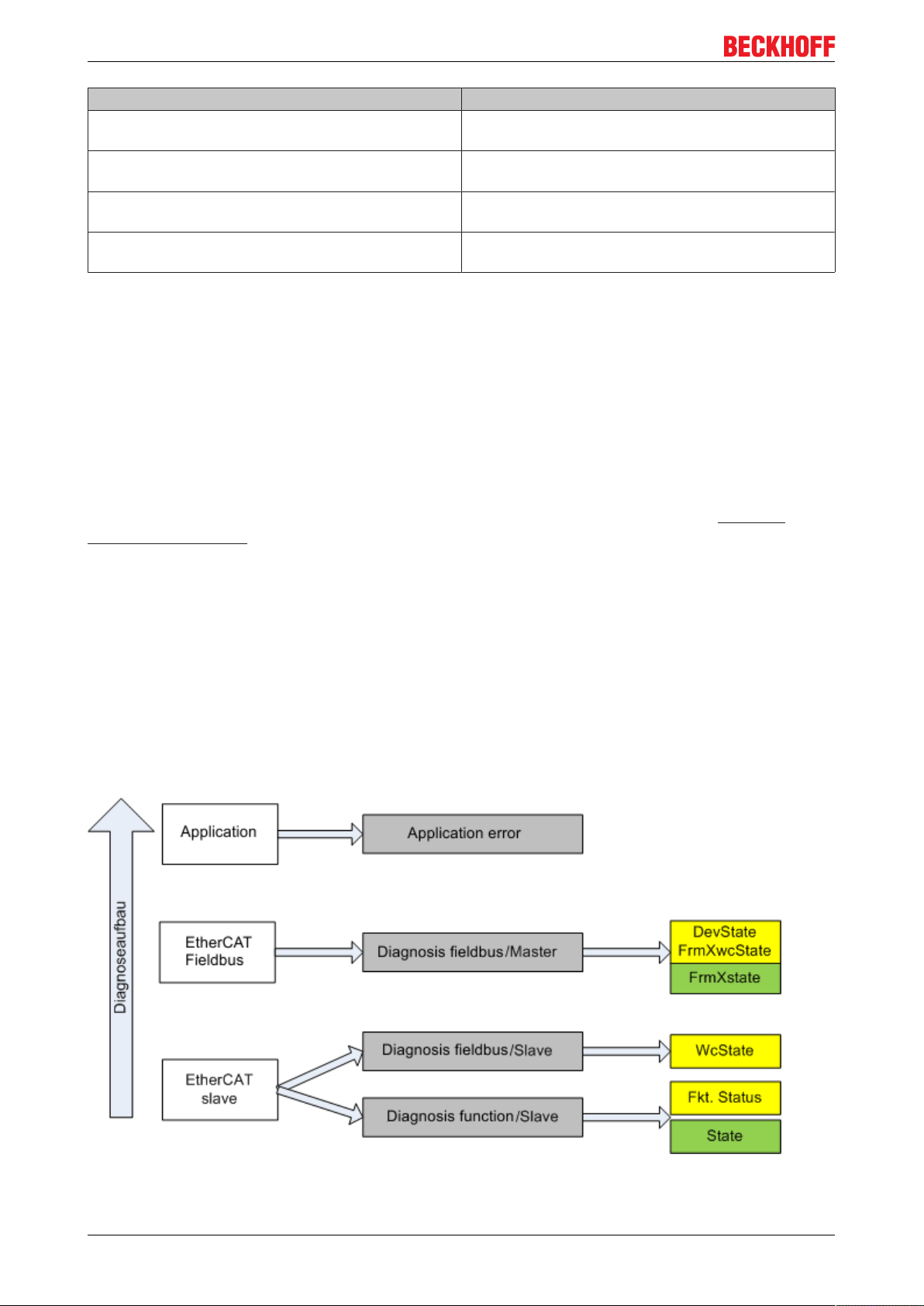
Commissioning
Status Description
No Carrier / Open No carrier signal is available at the port, but the port
is open.
No Carrier / Closed No carrier signal is available at the port, and the port
is closed.
Carrier / Open A carrier signal is available at the port, and the port is
open.
Carrier / Closed A carrier signal is available at the port, but the port is
closed.
File Access over EtherCAT
Download With this button a file can be written to the EtherCAT
device.
Upload With this button a file can be read from the EtherCAT
device.
5.2 General Notes - EtherCAT Slave Application
This summary briefly deals with a number of aspects of EtherCAT Slave operation under TwinCAT. More
detailed information on this may be found in the corresponding sections of, for instance, the EtherCAT
System Documentation.
Diagnosis in real time: WorkingCounter, EtherCAT State and Status
Generally speaking an EtherCAT Slave provides a variety of diagnostic information that can be used by the
controlling task.
This diagnostic information relates to differing levels of communication. It therefore has a variety of sources,
and is also updated at various times.
Any application that relies on I/O data from a fieldbus being correct and up to date must make diagnostic
access to the corresponding underlying layers. EtherCAT and the TwinCAT System Manager offer
comprehensive diagnostic elements of this kind. Those diagnostic elements that are helpful to the controlling
task for diagnosis that is accurate for the current cycle when in operation (not during commissioning) are
discussed below.
Fig.100: Selection of the diagnostic information of an EtherCAT Slave
EL70x790 Version 1.0
Page 91
Commissioning
In general, an EtherCAT Slave offers
• communication diagnosis typical for a slave (diagnosis of successful participation in the exchange of
process data, and correct operating mode)
This diagnosis is the same for all slaves.
as well as
• function diagnosis typical for a channel (device-dependent)
See the corresponding device documentation
The colors in Fig. “Selection of the diagnostic information of an EtherCAT Slave” also correspond to the
variable colors in the System Manager, see Fig. “Basic EtherCAT Slave Diagnosis in the PLC”.
Colour Meaning
yellow Input variables from the Slave to the EtherCAT Master, updated in every cycle
red Output variables from the Slave to the EtherCAT Master, updated in every cycle
green Information variables for the EtherCAT Master that are updated acyclically. This means that
it is possible that in any particular cycle they do not represent the latest possible status. It is
therefore useful to read such variables through ADS.
Fig. “Basic EtherCAT Slave Diagnosis in the PLC” shows an example of an implementation of basic
EtherCAT Slave Diagnosis. A Beckhoff EL3102 (2-channel analogue input terminal) is used here, as it offers
both the communication diagnosis typical of a slave and the functional diagnosis that is specific to a channel.
Structures are created as input variables in the PLC, each corresponding to the process image.
EL70x7 91Version 1.0
Page 92

Commissioning
Fig.101: Basic EtherCAT Slave Diagnosis in the PLC
The following aspects are covered here:
EL70x792 Version 1.0
Page 93

Commissioning
Code Function Implementation Application/evaluation
A The EtherCAT Master's
diagnostic information
updated acyclically (yellow) or
provided acyclically (green).
B In the example chosen (EL3102)
the EL3102 comprises two
analogue input channels that
transmit a single function status
for the most recent cycle.
C For every EtherCAT Slave that
has cyclic process data, the
Master displays, using what is
known as a WorkingCounter,
whether the slave is participating
successfully and without error in
the cyclic exchange of process
data. This important, elementary
information is therefore provided
for the most recent cycle in the
System Manager
1. at the EtherCAT Slave,
and, with identical contents
2. as a collective variable at
the EtherCAT Master (see
Point A)
for linking.
Status
• the bit significations
may be found in the
device documentation
• other devices may
supply more
information, or none
that is typical of a
slave
WcState (Working Counter)
0: valid real-time
communication in the last
cycle
1: invalid real-time
communication
This may possibly have
effects on the process data
of other Slaves that are
located in the same
SyncUnit
At least the DevState is to be
evaluated for the most recent cycle
in the PLC.
The EtherCAT Master's diagnostic
information offers many more
possibilities than are treated in the
EtherCAT System Documentation.
A few keywords:
• CoE in the Master for
communication with/through
the Slaves
• Functions from
TcEtherCAT.lib
• Perform an OnlineScan
In order for the higher-level PLC
task (or corresponding control
applications) to be able to rely on
correct data, the function status
must be evaluated there. Such
information is therefore provided
with the process data for the most
recent cycle.
In order for the higher-level PLC
task (or corresponding control
applications) to be able to rely on
correct data, the communication
status of the EtherCAT Slave must
be evaluated there. Such
information is therefore provided
with the process data for the most
recent cycle.
EL70x7 93Version 1.0
Page 94

Commissioning
Code Function Implementation Application/evaluation
D Diagnostic information of the
EtherCAT Master which, while it is
represented at the slave for
linking, is actually determined by
the Master for the Slave
concerned and represented there.
This information cannot be
characterized as real-time,
because it
• is only rarely/never
changed, except when the
system starts up
• is itself determined
acyclically (e.g. EtherCAT
Status)
State
current Status (INIT..OP) of
the Slave. The Slave must
be in OP (=8) when
operating normally.
AdsAddr
The ADS address is useful
for communicating from the
PLC/task via ADS with the
EtherCAT Slave, e.g. for
reading/writing to the CoE.
The AMS-NetID of a slave
corresponds to the AMSNetID of the EtherCAT
Master; communication with
the individual Slave is
possible via the port (=
EtherCAT address).
Information variables for the
EtherCAT Master that are updated
acyclically. This means that it is
possible that in any particular cycle
they do not represent the latest
possible status. It is therefore
possible to read such variables
through ADS.
Diagnostic information
It is strongly recommended that the diagnostic information made available is evaluated so
Attention
that the application can react accordingly.
CoE Parameter Directory
The CoE parameter directory (CanOpen-over-EtherCAT) is used to manage the set values for the slave
concerned. Changes may, in some circumstances, have to be made here when commissioning a relatively
complex EtherCAT Slave. It can be accessed through the TwinCAT System Manager, see Fig. “EL3102,
CoE directory”:
Fig.102: EL3102, CoE directory
EL70x794 Version 1.0
Page 95

Commissioning
EtherCAT System Documentation
The comprehensive description in the EtherCAT System Documentation (EtherCAT Basics
Note
A few brief extracts:
• Whether changes in the online directory are saved locally in the slave depends on the device. EL
terminals (except the EL66xx) are able to save in this way.
• The user must manage the changes to the StartUp list.
--> CoE Interface) must be observed!
Commissioning aid in the TwinCAT System Manager
Commissioning interfaces are being introduced as part of an ongoing process for EL/EP EtherCAT devices.
These are available in TwinCAT System Managers from TwinCAT 2.11R2 and above. They are integrated
into the System Manager through appropriately extended ESI configuration files.
Fig.103: Example of commissioning aid for a EL3204
This commissioning process simultaneously manages
• CoE Parameter Directory
• DC/FreeRun mode
• the available process data records (PDO)
Although the "Process Data", "DC", "Startup" and "CoE-Online" that used to be necessary for this are still
displayed, it is recommended that, if the commissioning aid is used, the automatically generated settings are
not changed by it.
The commissioning tool does not cover every possible application of an EL/EP device. If the available setting
options are not adequate, the user can make the DC, PDO and CoE settings manually, as in the past.
EtherCAT State: automatic default behaviour of the TwinCAT System Manager and
manual operation
After the operating power is switched on, an EtherCAT Slave must go through the following statuses
• INIT
• PREOP
EL70x7 95Version 1.0
Page 96

Commissioning
• SAFEOP
• OP
to ensure sound operation. The EtherCAT Master directs these statuses in accordance with the initialization
routines that are defined for commissioning the device by the ES/XML and user settings (Distributed Clocks
(DC), PDO, CoE). See also the section on "Principles of Communication, EtherCAT State Machine [}30]" in
this connection. Depending how much configuration has to be done, and on the overall communication,
booting can take up to a few seconds.
The EtherCAT Master itself must go through these routines when starting, until it has reached at least the
OP target state.
The target state wanted by the user, and which is brought about automatically at start-up by TwinCAT, can
be set in the System Manager. As soon as TwinCAT reaches the status RUN, the TwinCAT EtherCAT
Master will approach the target states.
Standard setting
The advanced settings of the EtherCAT Master are set as standard:
• EtherCAT Master: OP
• Slaves: OP
This setting applies equally to all Slaves.
Fig.104: Default behaviour of the System Manager
In addition, the target state of any particular Slave can be set in the "Advanced Settings" dialogue; the
standard setting is again OP.
EL70x796 Version 1.0
Page 97

Fig.105: Default target state in the Slave
Commissioning
Manual Control
There are particular reasons why it may be appropriate to control the states from the application/task/PLC.
For instance:
• for diagnostic reasons
• to induce a controlled restart of axes
• because a change in the times involved in starting is desirable
In that case it is appropriate in the PLC application to use the PLC function blocks from the TcEtherCAT.lib,
which is available as standard, and to work through the states in a controlled manner using, for instance,
FB_EcSetMasterState.
It is then useful to put the settings in the EtherCAT Master to INIT for master and slave.
Fig.106: PLC function blocks
EL70x7 97Version 1.0
Page 98

Commissioning
Note regarding E-Bus current
EL/ES terminals are placed on the DIN rail at a coupler on the terminal strand. A Bus Coupler can supply the
EL terminals added to it with the E-bus system voltage of 5 V; a coupler is thereby loadable up to 2 A as a
rule. Information on how much current each EL terminal requires from the E-bus supply is available online
and in the catalogue. If the added terminals require more current than the coupler can supply, then power
feed terminals (e.g. EL9410) must be inserted at appropriate places in the terminal strand.
The pre-calculated theoretical maximum E-Bus current is displayed in the TwinCAT System Manager as a
column value. A shortfall is marked by a negative total amount and an exclamation mark; a power feed
terminal is to be placed before such a position.
Fig.107: Illegally exceeding the E-Bus current
From TwinCAT 2.11 and above, a warning message "E-Bus Power of Terminal..." is output in the logger
window when such a configuration is activated:
Fig.108: Warning message for exceeding E-Bus current
Caution! Malfunction possible!
The same ground potential must be used for the E-Bus supply of all EtherCAT terminals in
Attention
a terminal block!
EL70x798 Version 1.0
Page 99

Commissioning
5.3 Start-up and parameter configuration
5.3.1 Process data
Sync Manager (SM)
Sync Manager (SM) The scope of the offered process data can be changed via the "Process data" tab (see
Fig. "Tab Process data SM2, EL70xx (default), Process data tab SM3, EL70xx (default)").
Fig.109: Process Data tab SM2, EL70xx (default)
EL70x7 99Version 1.0
Page 100

Commissioning
Fig.110: Process Data tab SM3, EL70xx (default)
PDO Assignment
In order to configure the process data, select the desired Sync Manager (SM 2 & 3 can be edited) in the
upper left-hand "Sync Manager" box (see fig.). The process data assigned to this Sync Manager can then be
switched on or off in the "PDO Assignment" box underneath. Restarting the EtherCAT system, or reloading
the configuration in configuration mode (F4), causes the EtherCAT communication to restart, and the
process data is transferred from the terminal.
EL70x7100 Version 1.0
 Loading...