

Page 1
Documentation
EL6900-FB, KL6904-FB
TwinCAT function blocks for TwinSAFE logic terminals
Version: 2.4.1
Date: 2015-03-11
Page 2

Page 3

Table of contents
Table of contents
1 Foreword 5
1.1 Notes on the manual 5
1.1.1 Disclaimer 5
1.1.2 Brands 5
1.1.3 Patents 5
1.1.4 Copyright 5
1.1.5 Delivery conditions 5
1.2 Safety instructions 6
1.2.1 Delivery state 6
1.2.2 Operator's obligation to exercise diligence 6
1.2.3 Description of safety symbols 7
1.2.4 Origin of the document 7
1.2.5 Documentation issue status 8
2 System description 9
2.1 TwinSAFE logic terminals EL6900/KL6904 9
2.1.1 TwinSAFE group 9
2.1.2 TwinSAFE connection 11
2.1.3 System diagnosis 11
3 Function blocks 17
3.1 The AND function block 17
3.1.1 Functional description 17
3.1.2 Signal description 18
3.1.3 FB AND configuration in the TwinCAT System Manager 20
3.2 The OR function block 21
3.2.1 Functional description 21
3.2.2 Signal description 22
3.2.3 FB OR configuration in the TwinCAT System Manager 24
3.3 The OPMODE function block 25
3.3.1 Functional description 25
3.3.2 Signal description 26
3.3.3 FB OPMODE configuration in the TwinCAT System Manager 29
3.4 The ESTOP function block 30
3.4.1 Functional description 30
3.4.2 Signal description 31
3.4.3 FB ESTOP configuration in the TwinCAT System Manager 33
3.5 The MON function block 35
3.5.1 Functional description 35
Function blocks for TwinSAFE logic terminals 1
Page 4

Table of contents
3.5.2 Signal description 37
3.5.3 FB MON configuration in the TwinCAT System Manager 39
3.6 The DECOUPLE function block 41
3.6.1 Functional description 41
3.6.2 Signal description 42
3.6.3 FB DECOUPLE configuration in the TwinCAT System Manager 45
3.7 The TWO-HAND function block 46
3.7.1 Functional description 46
3.7.2 Signal description 47
3.7.3 FB TWO-HAND configuration in the TwinCAT System Manager 49
3.7.4 Examples of two-hand control types according to DIN EN 574 : 1996 50
3.8 The MUTING function block 51
3.8.1 Functional description 51
3.8.2 Signal description 52
3.8.3 FB MUTING configuration in the TwinCAT System Manager 55
3.9 The EDM function block 61
3.9.1 Functional description 61
3.9.2 Signal description 62
3.9.3 FB EDM configuration in the TwinCAT System Manager 63
3.10 The RS function block 64
3.10.1 Functional description 64
3.10.2 Signal description 65
3.10.3 FB RS configuration in the TwinCAT System Manager 66
3.11 The SR function block 67
3.11.1 Functional description 67
3.11.2 Signal description 68
3.11.3 FB SR configuration in the TwinCAT System Manager 69
3.12 The TON function block 70
3.12.1 Functional description 70
3.12.2 Signal description 71
3.12.3 FB TON configuration in the TwinCAT System Manager 72
3.13 The TOF function block 73
3.13.1 Functional description 73
3.13.2 Signal description 74
3.13.3 FB TOF configuration in the TwinCAT System Manager 75
3.14 The CONNECTION SHUTDOWN function block 76
3.14.1 Functional description 76
3.14.2 Signal description 78
3.14.3 FB ConnectionShutdown configuration in the TwinCAT System Manager 80
2
Function blocks for TwinSAFE logic terminals
Page 5

Table of contents
4 Appendix 81
4.1 Beckhoff Support and Service 81
4.1.1 Beckhoff branches and partner companies Beckhoff Support 81
4.1.2 Beckhoff company headquarters 81
Function blocks for TwinSAFE logic terminals 3
Page 6

Page 7

Foreword
1 Foreword
1.1 Notes on the manual
This description is only intended for the use of trained specialists in control and automation technology
familiar with the applicable national standards. It is essential that the following notes and explanations are
followed when installing and commissioning these components.
The responsible staff must ensure that the application or use of the products described satisfy all the
safety requirements, including all the relevant laws, regulations, guidelines and standards.
1.1.1 Disclaimer
This documentation has been prepared with care. The products described are, however, constantly under
development. For this reason, the documentation may not always have been fully checked for
consistency with the performance data, standards or other characteristics described.
If it should contain technical or editorial errors, we reserve the right to make changes at any time and
without notice.
No claims for the modification of products that have already been supplied may be made on the basis of
the data, diagrams and descriptions in this documentation.
1.1.2 Brands
Beckhoff®, TwinCAT®, EtherCAT®, Safety over EtherCAT®, TwinSAFE® and XFC® are registered
trademarks of and licensed by Beckhoff Automation GmbH.
The use by third parties of other brand names or trademarks contained in this documentation may lead to
an infringement of the rights of the respective trademark owner.
1.1.3 Patents
The EtherCAT technology is patent protected, in particular by the following applications and patents:
EP1590927, EP1789857, DE102004044764, DE102007017835 with the corresponding applications and
registrations in various other countries.
The TwinCAT technology is patent protected, in particular by the following applications and patents:
EP0851348, US6167425 with the corresponding applications and registrations in various other countries.
1.1.4 Copyright
©
Beckhoff Automation GmbH & Co. KG.
The copying, distribution and utilization of this document as well as the communication of its contents to
others without express authorization is prohibited. Offenders shall be held liable for damages. All rights
conferred by patent grant or registration of a utility model or registered design are reserved.
1.1.5 Delivery conditions
In addition, the general delivery conditions of the company Beckhoff Automation GmbH & Co. KG apply.
Function blocks for TwinSAFE logic terminals 5
Page 8

Foreword
1.2 Safety instructions
1.2.1 Delivery state
All the components are supplied in particular hardware and software configurations appropriate for the
application. Modifications to hardware or software configurations other than those described in the
documentation are not permitted, and nullify the liability of Beckhoff Automation GmbH & Co. KG.
1.2.2 Operator's obligation to exercise diligence
The operator must ensure that
• the TwinSAFE products are only used as intended (see section Product description);
• the TwinSAFE products are only operated in sound condition and in working order.
• the TwinSAFE products are operated only by suitably qualified and authorized personnel.
• the personnel is instructed regularly about relevant occupational safety and environmental
protection aspects, and is familiar with the operating instructions and in particular the safety
instructions contained herein.
• the operating instructions are in good condition and complete, and always available for reference
at the location where the TwinSAFE products are used.
• none of the safety and warning notes attached to the TwinSAFE products are removed, and all
notes remain legible.
6
Function blocks for TwinSAFE logic terminals
Page 9
Foreword
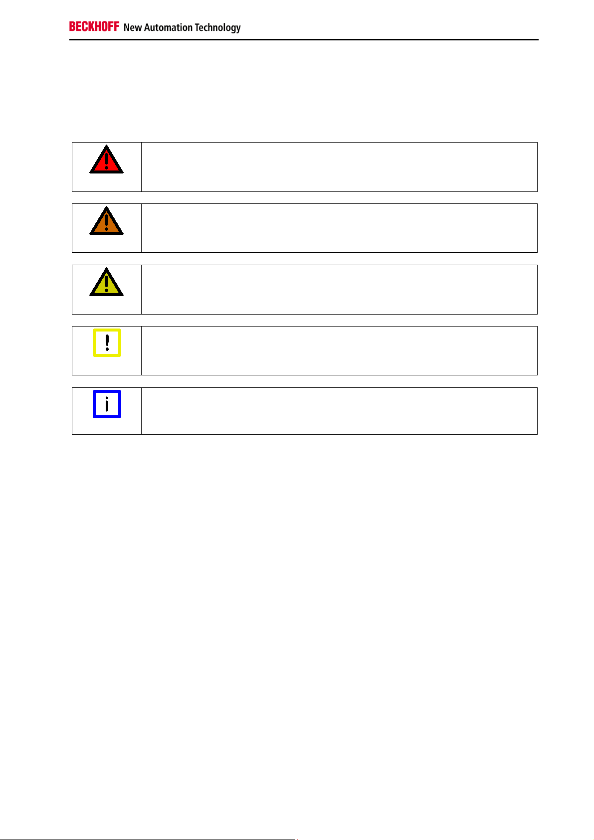
1.2.3 Description of safety symbols
The following safety symbols are used in these operating instructions. They are intended to alert the
reader to the associated safety instructions.
Serious risk of injury!
DANGER
WARNING
CAUTION
Attention
Note
Failure to follow the safety instructions associated with this symbol directly endangers
the life and health of persons.
Risk of injury!
Failure to follow the safety instructions associated with this symbol endangers the life
and health of persons.
Personal injuries!
Failure to follow the safety instructions associated with this symbol can lead to injuries
to persons.
Damage to the environment or devices
Failure to follow the instructions associated with this symbol can lead to damage to the
environment or equipment.
Tip or pointer
This symbol indicates information that contributes to better understanding.
1.2.4 Origin of the document
This documentation was originally written in German. All other languages are derived from the German
original.
Function blocks for TwinSAFE logic terminals 7
Page 10
Foreword
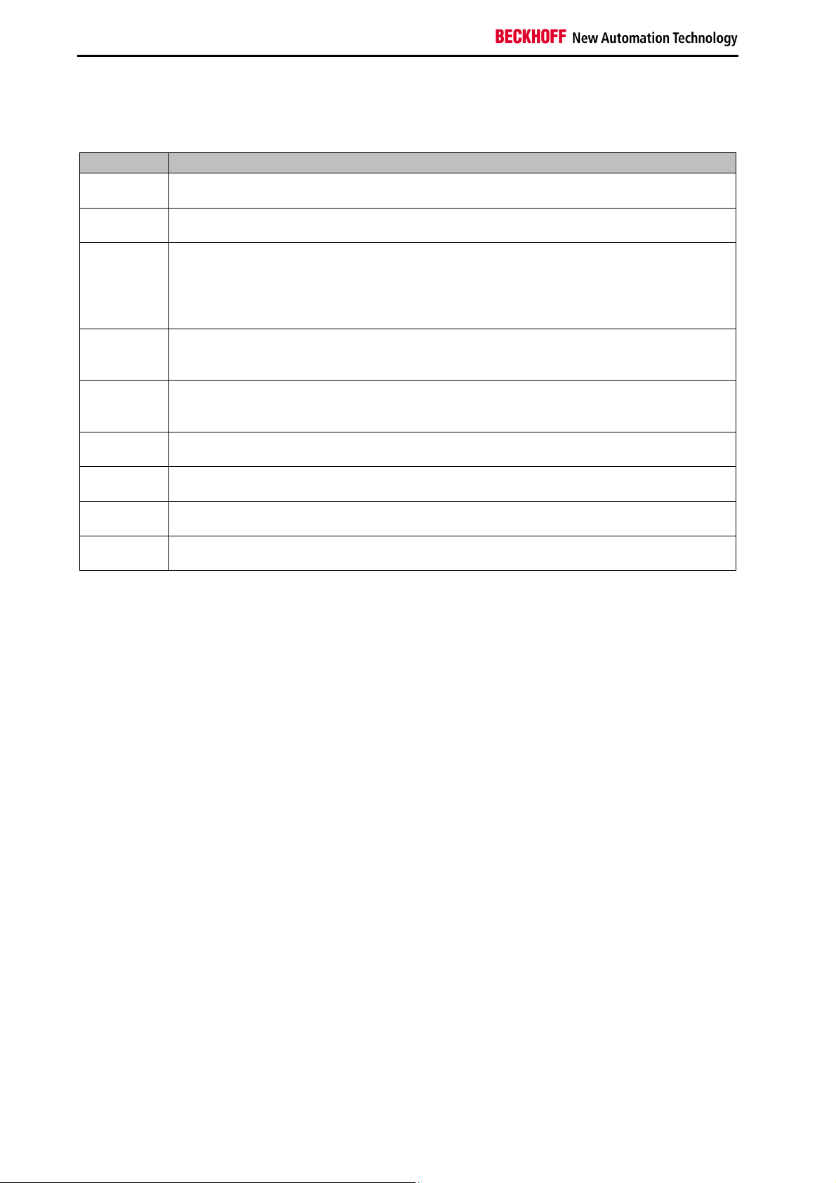
1.2.5 Documentation issue status
Version Comment
2.4.1
• Markings removed
2.4.0
2.3.0
2.2.0
2.1.0
2.0.0
1.1.1
1.1.0
1.0.0
• Company address changed
• Document origin and versions added
• EDM extended with standard In
• MUTING status information expanded
• Two-hand diagnostic information expanded
• TwinSAFE connection info data expanded
• FB ESTOP info data expanded
• FB OPMODE description expanded
• Service/support information modified
• EL6900 blocks added
• Corrections during the translation into English
• Amendments in the application examples
• First released version
8
Function blocks for TwinSAFE logic terminals
Page 11

System description
2 System description
The TwinSAFE system consists of safe inputs (EL/KL1904), safe outputs (EL/KL2904) and logic modules
(KL6904/EL6900). The TwinSAFE logic terminal (KL6904/EL6900) contains function blocks, which can be
parameterized and connected to each other and form the safety-related logic. Free programming is not
possible. In addition to the non-safety-related logic configuration a fieldbus configuration is required for
mapping the TwinSAFE data packets. These functions are realized via the TwinCAT System Manager.
The safety-related TwinSAFE Verifier, which is available at the moment as a separate installation, deals
with the loading and testing of the TwinSAFE project onto the EL6900/KL6904.
The TwinSAFE logic terminal can communicate, via the fieldbus-independent and certified TwinSAFEprotocol with safe input and output terminals, and also via further logic terminals. The TwinSAFE protocol
is a Safety over EtherCAT (FSoE) protocol with one byte of safe user data. It is openly available via the
EtherCAT Technology Group (www.ethercat.org).
2.1 TwinSAFE logic terminals EL6900/KL6904
The configuration of a TwinSAFE logic terminal consists of function blocks that are consolidated into one
or several TwinSAFE groups. TwinSAFE groups can be started and stopped independently of each other.
The execution sequence of the function blocks corresponds to the TwinCAT System Managers project
structure sequence illustrated. This sequence can be changed in the System Manager by Drag’n Drop.
The function blocks have parameters which must be configured by the user.
The inputs and outputs of the function blocks are assigned to the inputs and outputs of the TwinSAFE
terminals, to other function blocks or to the input and output variable of the standard PLC by the user.
A TwinSAFE connection involves unambiguous assignment of a TwinSAFE device (EL/KL1904,
EL/KL2904, EL6900/KL6904) to TwinSAFE group. Only function blocks which belong to this TwinSAFE
group can be linked with the input and outputs of an assigned TwinSAFE connection. The DECOUPLE
block can be used if it is necessary for other groups to access the inputs and outputs (see chapter 3.6).
Errors of the TwinSAFE communication within the TwinSAFE group and errors within a function block
affect the complete TwinSAFE group. The TwinSAFE group then stops all associated function blocks,
which then switch their outputs into a safe state.
Errors in the TwinSAFE Logic result in it switching off completely.
2.1.1 TwinSAFE group
The function blocks are assigned to TwinSAFE groups. These have a characteristic that results in the
return of all group outputs to a safe state (a safe state is always a wattless state at the output,
corresponding to a logical 0) such as, in case of a communication error of an assigned TwinSAFE
connection, in case of an error in assigned function blocks (e.g. excessive discrepancy time) or an error in
the local assigned outputs. I.e. the TwinSAFE connection data and thus TwinSAFE input or output
terminal are always exactly assigned to a TwinSAFE group.
A communication error is displayed on the output (COM ERR) of the TwinSAFE group and acknowledged
on the input (ERR ACK). A function block error is displayed on the output (FB ERR) and acknowledged
on the same input (ERR ACK) as the communication error. An error on the local outputs (only KL6904) is
displayed on the third output (OUT ERR) and once again acknowledged (ERR_ACK) on the same input.
The safe state of the TwinSAFE group outputs is removed once the error is no longer present and has
been acknowledged.
The error acknowledgement is not carried out automatically, i.e. the "ERR ACK" input must always be
Function blocks for TwinSAFE logic terminals 9
Page 12
System description
linked.
Apart from this the TwinSAFE group has an input (RUN), with which the processing of the assigned
function blocks can be stopped and started. All TwinSAFE group assigned outputs are in a safe state
when stopped.
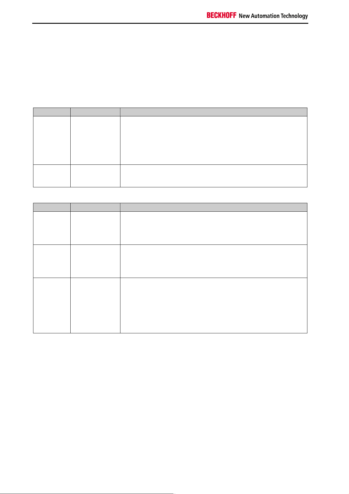
2.1.1.1 TwinSAFE group inputs and outputs
Table 2-1: TwinSAFE group inputs
Name Permitted type Description
RUN FB-Out
Standard-In
TRUE:
The function blocks assigned to the TwinSAFE group are executed
FALSE:
All assigned function blocks of the TwinSAFE group are at a STOP
state and thus all associated outputs are in a safe state
When the input is not linked it is in the TRUE state
ERR ACK FB-Out
Standard-In
All pending errors in the assigned function blocks and in the
TwinSAFE connections are acknowledged by the FALSE->TRUE>FALSE signal sequence.
Table 2-2: TwinSAFE group outputs
Name Permitted type Description
FB ERR TwinSAFE-Out
FB-In
Standard-Out
Local-Out
COM ERR TwinSAFE-Out
FB-In
Standard-Out
Local-Out
OUT ERR TwinSAFE-Out
FB-In
Standard-Out
Local-Out
TRUE:
At least one assigned function block has an error
FALSE:
All assigned function blocks have no errors
TRUE:
At least one TwinSAFE connection of TwinSAFE group has an error
FALSE:
All TwinSAFE connections of the TwinSAFE group have no errors
TRUE:
At least one local output assigned to the TwinSAFE group has an
error
FALSE:
All of the local outputs assigned to the TwinSAFE group have no
errors
Always FALSE for EL6900, since the device has no local outputs.
10
Function blocks for TwinSAFE logic terminals
Page 13
System description
2.1.2 TwinSAFE connection
Each safe communication path between the TwinSAFE logic and TwinSAFE inputs, TwinSAFE outputs or
other TwinSAFE logic terminals are referred to as TwinSAFE connection.
A communication partner is thus always the TwinSAFE master, the other the TwinSAFE slave. The
TwinSAFE logic is in a TwinSAFE connection to a TwinSAFE input or TwinSAFE output is always
TwinSAFE master. The TwinSAFE connection to another TwinSAFE logic can be TwinSAFE slave on the
other hand, whereby the TwinCAT System Manager automatically defines this assignment.
Both the TwinSAFE master and the TwinSAFE slave have a FSoE (Safety over EtherCAT) address that
can be set on the respective TwinSAFE terminal via a DIP switch in order to ensure that any mix-up of the
TwinSAFE data packets is always detected. These FSoE addresses are checked within the TwinSAFE
communication and must be unambiguous in the control system. The TwinSAFE Verifier for each
TwinSAFE logic terminal checks that. The TwinSAFE logic control system may contain several TwinSAFE
logic terminals, although the TwinSAFE Verifier can only be active for one TwinSAFE logic terminal at a
time. The user must therefore ensure that multiple allocation of FSoE addresses is avoided.
For each TwinSAFE connection a watchdog time and the corresponding FSoE address for the
communication devices can be set. In addition there is a possibility to adjust the SIL level, however this
setting is not supported at the moment and has no effects on the safety behavior of the system. In
another configuration option a module error in the TwinSAFE communication partner can be set to trigger
a communication error in the TwinSAFE group.
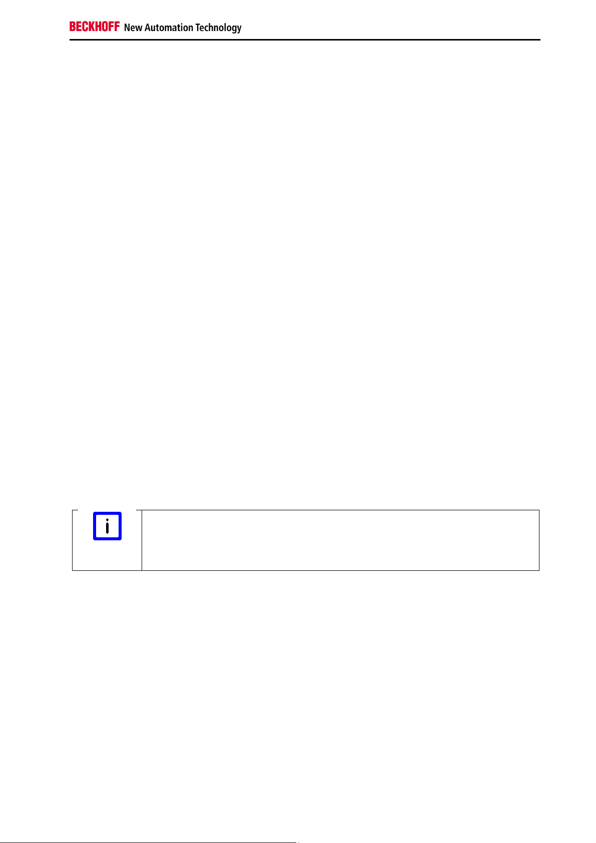
2.1.3 System diagnosis
The states of the TwinSAFE groups, FBs and connections can be checked in the System Manager. The
diagnostic information can be copied into the cyclic process image.
TwinSAFE groups have inputs and outputs of associated Screenshots assigned offline and which can be
considered online.
If the checkboxes ‘Map State’ and ‘Map Diag’ are set, the state and diagnostic data for the group are
copied into the cyclic process image and can be linked directly with PLC variables. The diagnostic data
are currently always 0.
KL6904
Note
With the KL6904 copying of the diagnostic information to the cyclic process image is
only possible to a limited extent. The checkboxes ‘Map State’ and ‘Map Diag’ are not
available.
Function blocks for TwinSAFE logic terminals 11
Page 14
System description
Figure 2-1: Inputs/Outputs
Table 2-3: Status information
Value Status Description
1 RUN
All function blocks and TwinSAFE connections assigned to the TwinSAFE
group operate properly, and all TwinSAFE connections assigned to the
TwinSAFE group are up and running
2 STOP State after initialization
3 SAFE
All function blocks and TwinSAFE connections assigned to the TwinSAFE
group operate properly, and at least one of the TwinSAFE connections
assigned to the TwinSAFE group is not yet up and running
4 ERROR
At least one assigned function block or one assigned TwinSAFE connection
has reported an error
5 RESET
A positive edge (FALSE->TRUE) for acknowledgement of a function block
or a TwinSAFE connection error was detected on the ERR_ACK input. The
system is waiting for the negative edge of the ERR_ACK input
12
Function blocks for TwinSAFE logic terminals
Page 15
System description
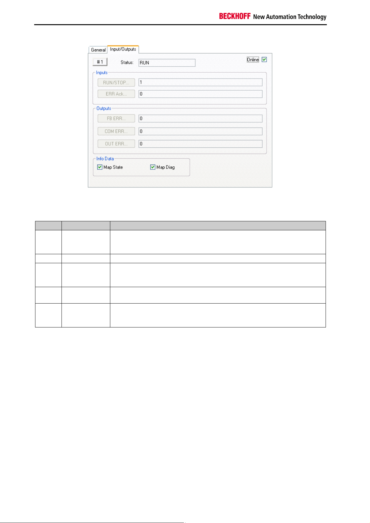
Figure 2-2: Inputs/Outputs
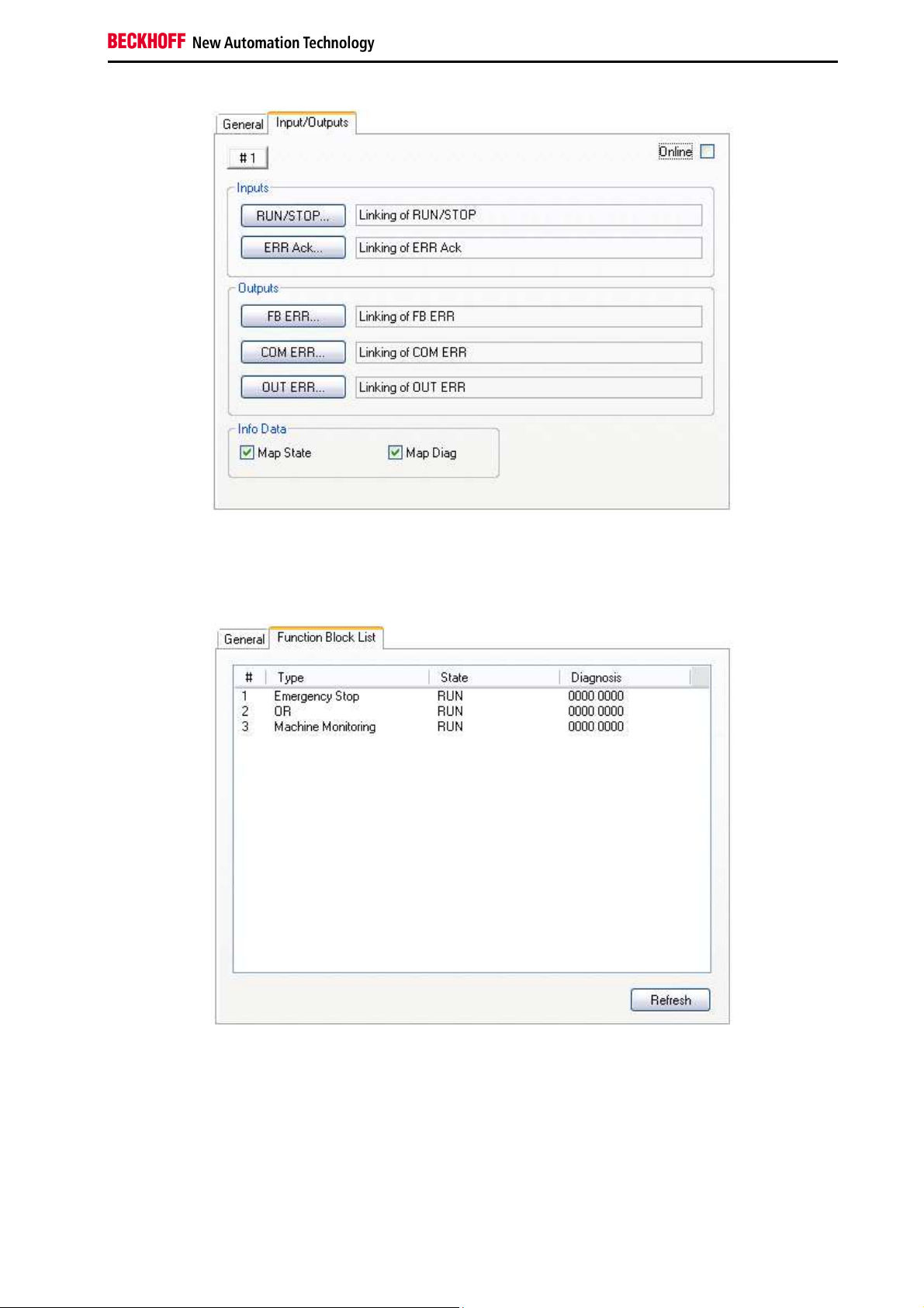
The status of TwinSAFE FBs is displayed on online summary. The current status data are read from the
EL6900/KL6904 via a manual refresh.
Figure 2-3: Function Block List
If the checkboxes ‘Map State’ and ‘Map Diag’ for the individual TwinSAFE FBs are set, the status and
diagnostic data for the FBs are copied into the cyclic process image and can be linked directly with PLC
variables. The description of the status and diagnostic values can be found under the respective FBs.
Function blocks for TwinSAFE logic terminals 13
Page 16
System description
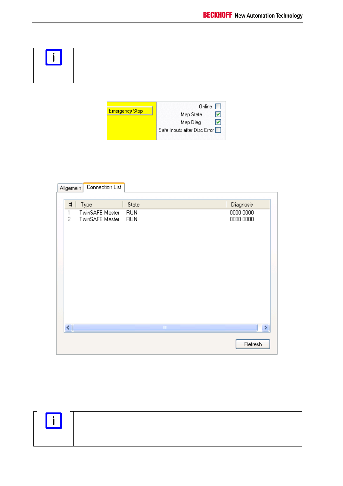
KL6904
Note
With the KL6904 copying of the diagnostic information to the cyclic process image is
only possible to a limited extent. The checkboxes ‘Map State’ and ‘Map Diag’ are not
available.
Figure 2-4: Emergency Stop
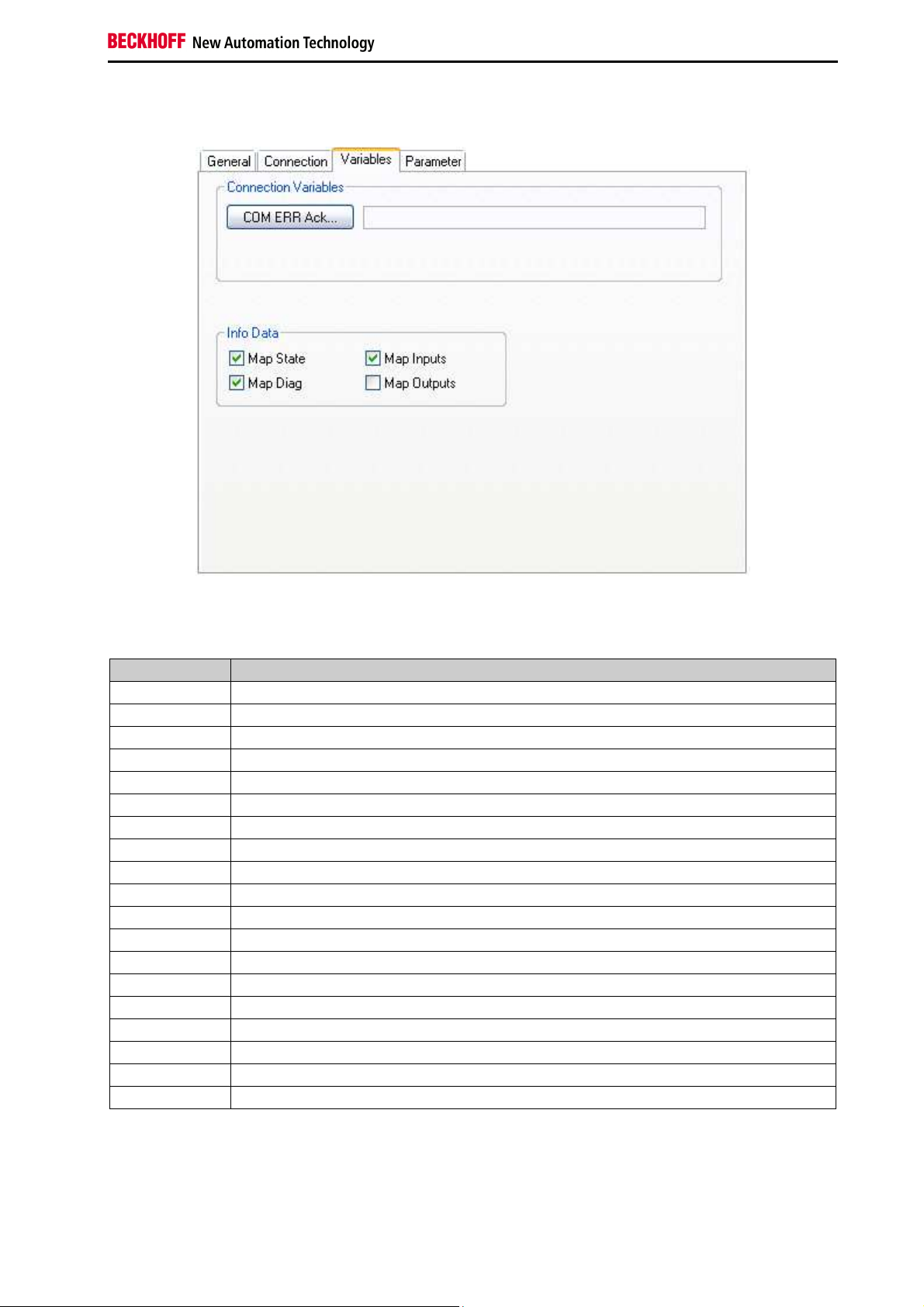
The TwinSAFE connections status is displayed on the TwinSAFE connection list summary under the
"Connection List" tab. Diagnostics bits are also set in addition to the status.
Figure 2-5: Connection List
If the checkboxes ‘Map State’ and ‘Map Diag’ for the individual TwinSAFE connections are set, the status
and diagnostic data for the connections are copied into the cyclic process image and can be linked
directly with PLC variables. In addition, the safe inputs and outputs can be copied into the cyclic process
image and used for diagnostic purposes.
KL6904
Note
With the KL6904 copying of the diagnostic information to the cyclic process image is
only possible to a limited extent. The checkboxes ‘Map State’, ‘Map Diag’‚ ‘Map Inputs’
and ‘Map Outputs’ are not available. The button “Com Err Ack” is also not available.
14
Function blocks for TwinSAFE logic terminals
Page 17
System description
Figure 2-6: Variables
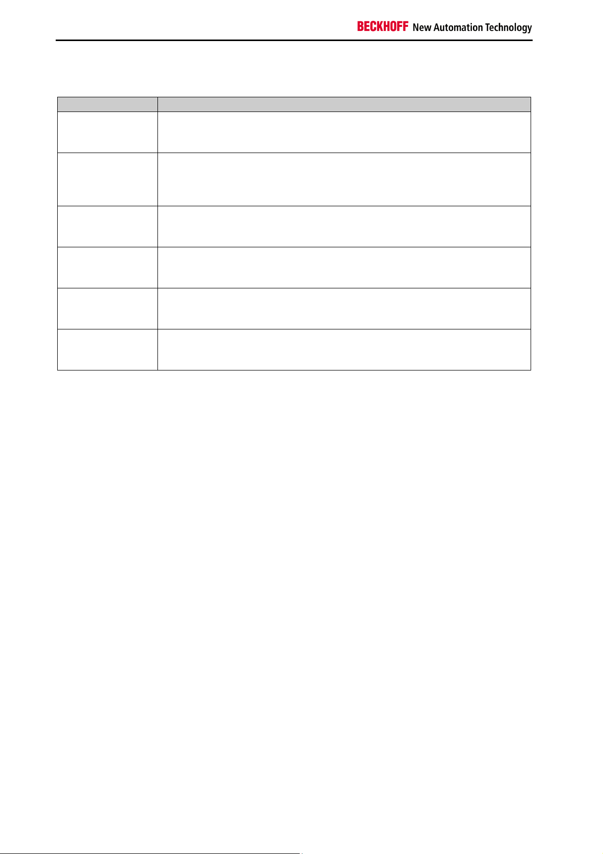
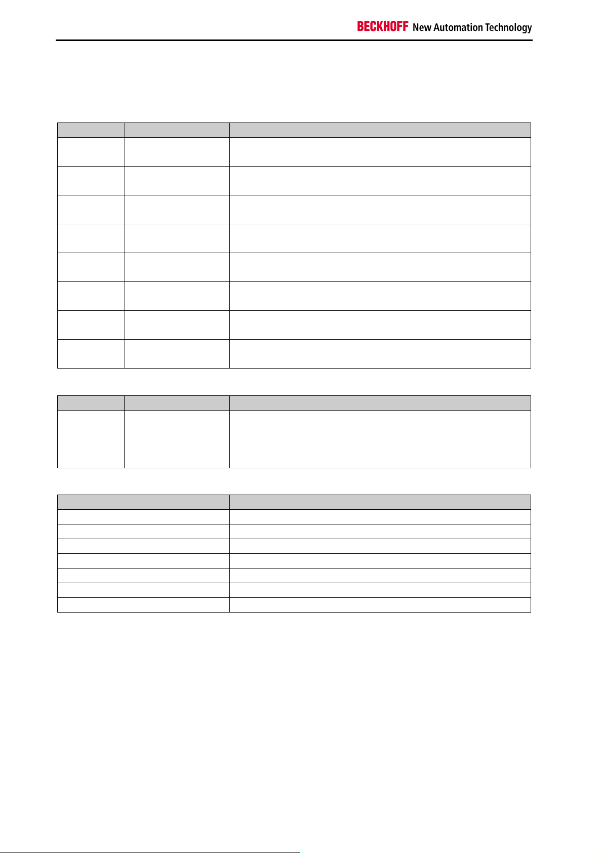
Table 2-4: Diagnostic information for a connection
Value Description
xxxx 0001 Invalid command
xxxx 0010 Unknown command
xxxx 0011 Invalid connection ID
xxxx 0100 Invalid CRC
xxxx 0101 Watchdog time elapsed
xxxx 0110 Invalid FSoE address
xxxx 0111 Invalid data
xxxx 1000 Invalid communication parameter length
xxxx 1001 Invalid communication parameters
xxxx 1010 Invalid user parameter length
xxxx 1011 Invalid user parameters
xxxx 1100 FSoE master reset
xxxx 1101 Module error detected on slave, with option "Module error is ComError" activated
xxxx 1110 Module error detected on EL290x, with option "Error acknowledge active" activated
xxxx 1111 Slave not yet started, or unexpected error argument
xxx1 xxxx FSoE slave error detected
xx1x xxxx FSoE slave reports Failsafe Value active
x1xx xxxx StartUp
1xxx xxxx FSoE master reports Failsafe Value active
Function blocks for TwinSAFE logic terminals 15
Page 18
System description
Table 2-5: Status information for a connection
Value Description
100 (0x64) Reset state:
The reset state is used to re-initialize the Safety over EtherCAT connection after
the power-on or a Safety over EtherCAT communication error.
101 (0x65) Session state:
During the transition to or in the session state a session ID is transferred from
the Safety over EtherCAT master to the Safety over EtherCAT slave, which in
turn responds with its own session ID.
102 (0x66) Connection state:
In the connection state a connection ID is transferred from the Safety over
EtherCAT master to the Safety over EtherCAT slave.
103 (0x67) Parameter state:
In the parameter state safe communication- and device-specific application
parameters are transferred.
104 (0x68) Data state:
In the data state Safety over EtherCAT cycles are transferred until either a
communication error occurs or a Safety over EtherCAT node is stopped locally.
105 (0x69) Shutdown state:
In the shutdown state the connection was shut down by one of the
communication partners.
Further information can be found in the Safety over EtherCAT specification.
16
Function blocks for TwinSAFE logic terminals
Page 19
Function blocks
3 Function blocks
The function blocks have a specified functionality that still must be configured via a parameter. The inputs
or outputs of a function block can be inputs or outputs of a local process image, but function block outputs
and inputs can be can be linked.
3.1 The AND function block
3.1.1 Functional description
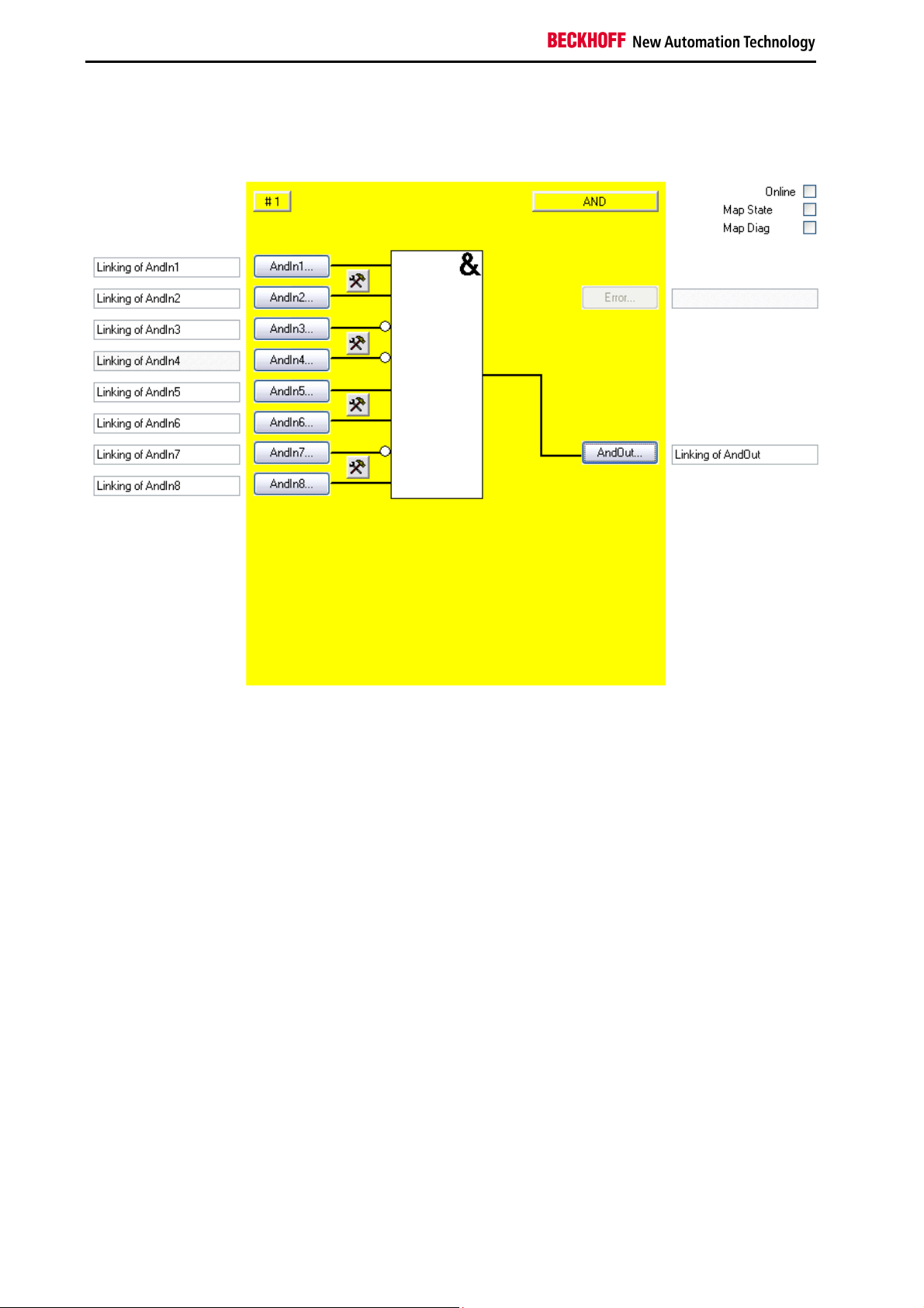
With the FB AND several input signals can be linked via AND to one output signal. In addition each input
can still be set even if the input signal is a normally closed contact (Break contact) or normally open
contact (Make contact). A normally open contact means that the corresponding input signal is negated,
before it affects the AND.
The AndIn1 input differs from the AndIn2-AndIn8 inputs in such a way that it can also be linked with a
standard input. This makes it possible to switch off a safe output using a standard signal. Outputs cannot
be switched on but only released using a standard signal, since at least two inputs must always be linked
for FB AND (and the second input is a safe one, which prevents switching on).
Figure 3-1: AND function block
Function blocks for TwinSAFE logic terminals 17
Page 20
Function blocks
3.1.2 Signal description
Table 3-1: FB AND inputs
Name Permitted type Description
AndIn1 TwinSAFE-In
FB-Out
Standard-In
AndIn2 TwinSAFE-In
FB-Out
AndIn3 TwinSAFE-In
FB-Out
AndIn4 TwinSAFE-In
FB-Out
AndIn5 TwinSAFE-In
FB-Out
AndIn6 TwinSAFE-In
FB-Out
AndIn7 TwinSAFE-In
FB-Out
AndIn8 TwinSAFE-In
FB-Out
1st input channel
2nd input channel
3rd input channel
4th input channel
5th input channel
6th input channel
7th input channel
8th input channel
Table 3-2: FB AND outputs
Name Permitted type Description
AndOut TwinSAFE-Out
Output channel
FB-In
Standard-Out
Local-Out
Table 3-3: FB AND input and output types
Type Description
TwinSAFE-In TwinSAFE input at an EL1904/KL1904
Standard-In Standard PLC variable (output in the PLC %Q*)
FB-Out TwinSAFE FB output
TwinSAFE-Out TwinSAFE output at an EL2904/KL2904
Standard-Out Standard PLC variable (input in the PLC %I*)
FB-In TwinSAFE FB input
Local-Out TwinSAFE output at the KL6904 (not available for EL6900)
18
Function blocks for TwinSAFE logic terminals
Page 21
Function blocks
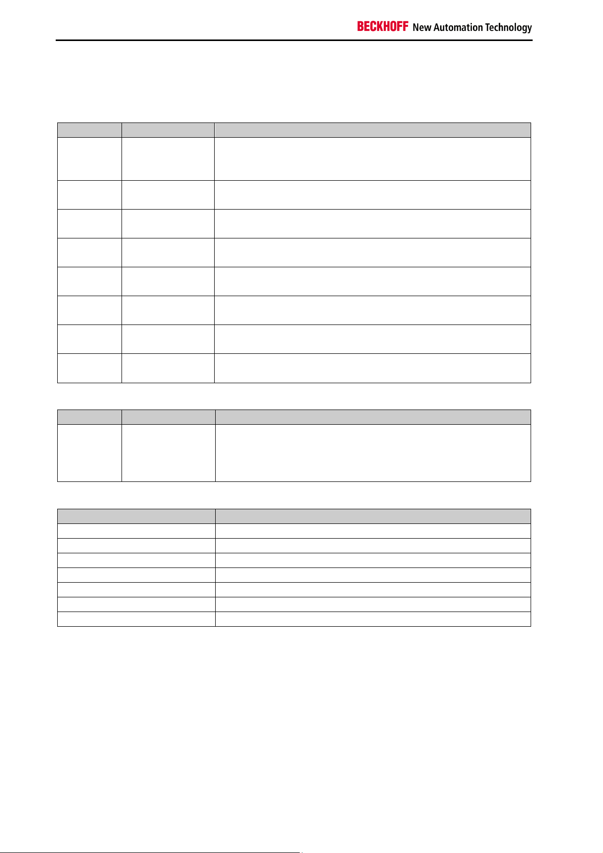
3.1.2.1 Diagnostic and status information for FB AND
Table 3-4: Diagnostic information (16-bit value)
Index Description
0-15 always 0
Table 3-5: Status information (8-bit value)
Index Description
0 undefined
1 RUN
2 STOP
3 SAFE
KL6904
Note
The checkboxes ‘Map State’ and ‘Map Diag’ are not available for the KL6904.
Function blocks for TwinSAFE logic terminals 19
Page 22
Function blocks
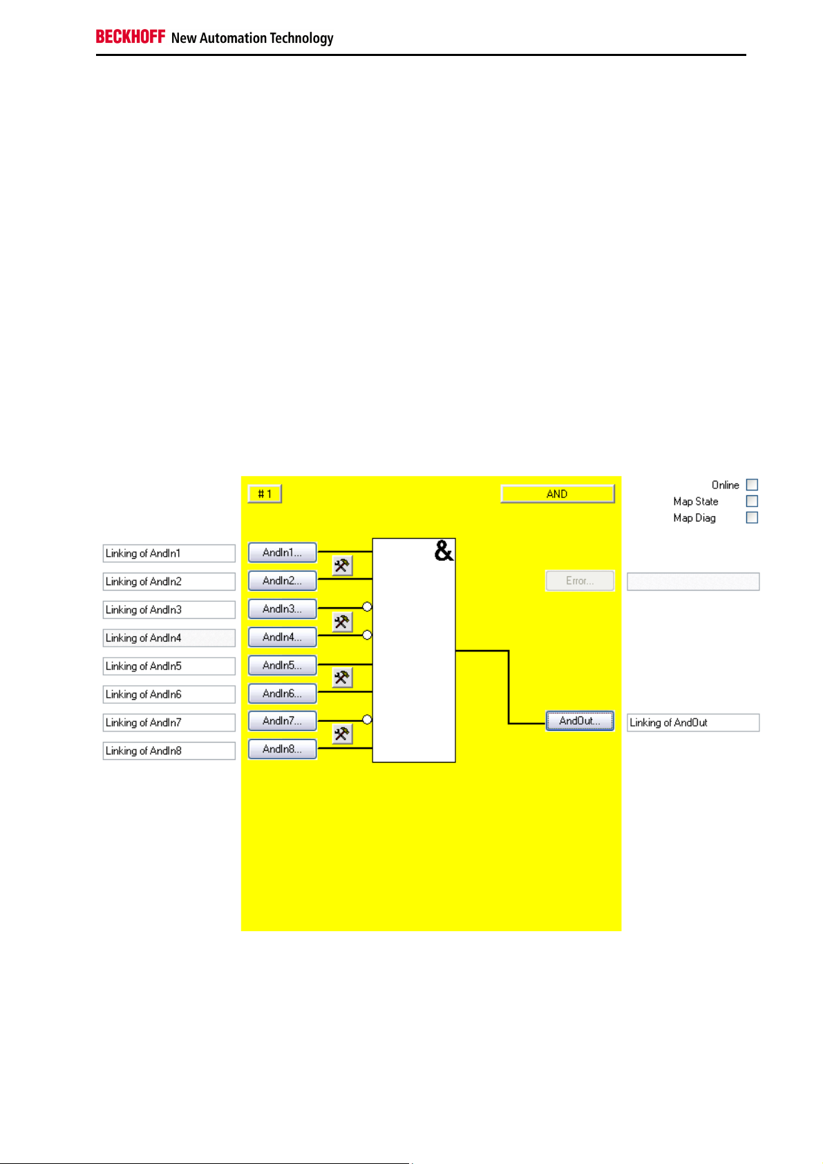
3.1.3 FB AND configuration in the TwinCAT System Manager
Figure 3-2: FB AND configuration
Their characteristics are configured with the setting buttons on the right near the two AndIn inputs,
whereby the inputs are always single-channel ones. A discrepancy monitoring cannot be used for the
AND.
The 'AndIn(x)' buttons can only be selected when the corresponding input has been activated. All inputs
are deactivated in the default setting.
The FB AND input variables are linked using the 'AndIn(x)' buttons.
The output variable of the FB AND are linked using the 'AndOut' button.
The ‘MapState’ and ‘MapDiag’ checkboxes are used to specify which FB diagnostic functions are mapped
to the cyclic process image.
The FB AND does not supply any error information and therefore the error button is basically deactivated.
20
Function blocks for TwinSAFE logic terminals
Page 23
Function blocks
3.2 The OR function block
3.2.1 Functional description
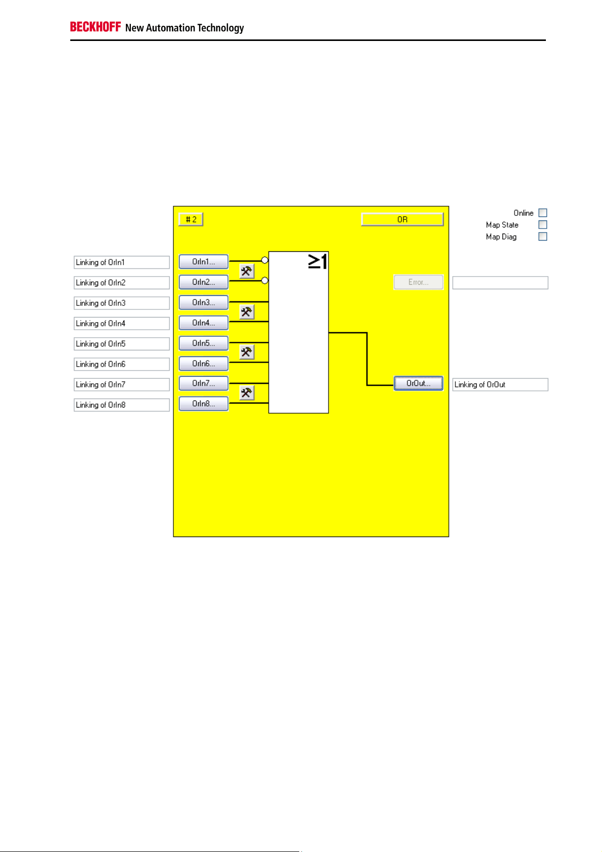
With the FB OR several input signals can be linked via OR to one output signal. In addition each input
can still be set even if the input signal is a normally closed contact (Break contact) or normally open
contact (Make contact). A normally open contact means that the corresponding input signal is negated,
before it affects the OR.
Figure 3-3: OR function block
Function blocks for TwinSAFE logic terminals 21
Page 24
Function blocks
3.2.2 Signal description
Table 3-6: FB OR inputs
Name Permitted type Description
OrIn1 TwinSAFE-In
FB-Out
OrIn2 TwinSAFE-In
FB-Out
OrIn3 TwinSAFE-In
FB-Out
OrIn4 TwinSAFE-In
FB-Out
OrIn5 TwinSAFE-In
FB-Out
OrIn6 TwinSAFE-In
FB-Out
OrIn7 TwinSAFE-In
FB-Out
OrIn8 TwinSAFE-In
FB-Out
1st input channel
2nd input channel
3rd input channel
4th input channel
5th input channel
6th input channel
7th input channel
8th input channel
Table 3-7: FB OR outputs
Name Permitted type Description
OrOut TwinSAFE-Out
Output channel
FB-In
Standard-Out
Local-Out
Table 3-8: FB OR input and output types
Type Description
TwinSAFE-In TwinSAFE input at an EL1904/KL1904
Standard-In Standard PLC variable (output in the PLC %Q*)
FB-Out TwinSAFE FB output
TwinSAFE-Out TwinSAFE output at an EL2904/KL2904
Standard-Out Standard PLC variable (input in the PLC %I*)
FB-In TwinSAFE FB input
Local-Out TwinSAFE output at the KL6904 (not available for EL6900)
22
Function blocks for TwinSAFE logic terminals
Page 25
Function blocks
3.2.2.1 Diagnostic and status information for FB OR
Table 3-9: Diagnostic information (16-bit value)
Index Description
0-15 always 0
Table 3-10: Status information (8-bit value)
Index Description
0 undefined
1 RUN
2 STOP
3 SAFE
KL6904
Note
The checkboxes ‘Map State’ and ‘Map Diag’ are not available for the KL6904.
Function blocks for TwinSAFE logic terminals 23
Page 26

Function blocks
3.2.3 FB OR configuration in the TwinCAT System Manager
Figure 3-4: FB OR configuration
Their characteristics are configured with the setting buttons on the right near the two OrIn inputs, whereby
the inputs are always single-channel. A discrepancy monitoring cannot be used for the OR.
The ‘OrIn(x)’ buttons are only available once the corresponding input was activated. In the default setting
all inputs are disabled.
The FB OR input variables are linked using the 'OrIn(x)' buttons.
The output variable of the FB OR are linked using the 'OrOut' button.
The ‘MapState’ and ‘MapDiag’ checkboxes are used to specify which FB diagnostic functions are mapped
to the cyclic process image.
The FB OR does not supply any error information and therefore the error button is basically deactivated.
24
Function blocks for TwinSAFE logic terminals
Page 27

Function blocks
3.3 The OPMODE function block
3.3.1 Functional description
Operating mode selectors can be realized with the FB OPMODE. The function block has 8 inputs and 8
outputs, which are looped through one-to-one, whereby up to 8 different operating modes can be
selected. The FB OPMODE sets the corresponding output, only when an input is precisely set ("1"),
whereby the other outputs remain in a safe (“0”) state. All outputs are in a safe state if there is none or
more than one input is set. The output safe state can only be exited during start and change of operating
modes using a 0->1->0 signal sequence on the restart input, once the restart input is activated. In
addition a discrepancy time can be given, with which the change of operating mode can be monitored.
Figure 3-5: Function block OPMODE
Number of inputs
Note
Function blocks for TwinSAFE logic terminals 25
At least two inputs of FB OPMODE must be connected.
Page 28

Function blocks
3.3.2 Signal description
Table 3-11: FB OPMODE inputs
Name Permitted type Description
Restart TwinSAFE-In
FB-Out
Standard-In
OpIn1 TwinSAFE-In
FB-Out
OpIn2 TwinSAFE-In
FB-Out
OpIn3 TwinSAFE-In
FB-Out
OpIn4 TwinSAFE-In
FB-Out
OpIn5 TwinSAFE-In
FB-Out
OpIn6 TwinSAFE-In
FB-Out
OpIn7 TwinSAFE-In
FB-Out
OpIn8 TwinSAFE-In
FB-Out
The 0->1->0 signal sequence must be detected on the restart input,
before the safe state of the outputs can be removed, when starting the
FB or when all outputs are switched to the safe state.
1st input channel
2nd input channel
3rd input channel
4th input channel
5th input channel
6th input channel
7th input channel
8th input channel
26
Function blocks for TwinSAFE logic terminals
Page 29

Function blocks
Table 3-12: FB OPMODE outputs
Name Permitted type Description
Error TwinSAFE-Out
FB-In
Standard-Out
Local-Out
TRUE:
The discrepancy time monitoring or the input monitoring has
found an error. The acknowledgement of the error must be
carried out via the ERR_ACK input of the related TwinSAFE
group
FALSE:
No error was found.
OpOut1 TwinSAFE-Out
1st output channel
FB-In
Standard-Out
Local-Out
OpOut2 TwinSAFE-Out
2nd output channel
FB-In
Standard-Out
Local-Out
OpOut3 TwinSAFE-Out
3rd output channel
FB-In
Standard-Out
Local-Out
OpOut4 TwinSAFE-Out
4th output channel
FB-In
Standard-Out
Local-Out
OpOut5 TwinSAFE-Out
5th output channel
FB-In
Standard-Out
Local-Out
OpOut6 TwinSAFE-Out
6th output channel
FB-In
Standard-Out
Local-Out
OpOut7 TwinSAFE-Out
7th output channel
FB-In
Standard-Out
Local-Out
OpOut8 TwinSAFE-Out
8th output channel
FB-In
Standard-Out
Local-Out
Function blocks for TwinSAFE logic terminals 27
Page 30

Function blocks
Table 3-13: FB OPMODE input and output types
Type Description
TwinSAFE-In TwinSAFE input at an EL1904/KL1904
Standard-In Standard PLC variable (output in the PLC %Q*)
FB-Out TwinSAFE FB output
TwinSAFE-Out TwinSAFE output at an EL2904/KL2904
Standard-Out Standard PLC variable (input in the PLC %I*)
FB-In TwinSAFE FB input
Local-Out TwinSAFE output at the KL6904 (not available for EL6900)
3.3.2.1 Diagnostic and status information for FB OPMODE
Table 3-14: Diagnostic information (16-bit value)
Index Description
0 Discrepancy monitoring error
Table 3-15: Status information (8-bit value)
Index Description
0 undefined
1 RUN
2 STOP
3 SAFE
4 ERROR
5 RESET
6 START
KL6904
Note
The checkboxes ‘Map State’ and ‘Map Diag’ are not available for the KL6904.
28
Function blocks for TwinSAFE logic terminals
Page 31

Function blocks
3.3.3 FB OPMODE configuration in the TwinCAT System Manager
Figure 3-6: FB OPMODE configuration
The manual restart is activated using the "'Activated' " checkbox on the right near the 'Restart' button.
The inputs are activated via the 'Activated' check boxes to the right of the 'OpIn (x)' button.
The 'Restart' or 'OpIn(x)' buttons can only be selected, once the corresponding check box has been
selected.
The FB OPMODE input variables are linked using the 'Restart' and 'OrIn(x)' buttons.
The FB OPMODE output variables are linked using the 'Error' and 'OpOut(x)' buttons.
The ‘MapState’ and ‘MapDiag’ checkboxes are used to specify which FB diagnostic functions are mapped
to the cyclic process image.
The discrepancy time is configured using the 'Discrepancy' selection box.
Function blocks for TwinSAFE logic terminals 29
Page 32

Function blocks
3.4 The ESTOP function block
3.4.1 Functional description
An emergency stop circuit with up to eight emergency stop inputs (EStopIn1-EStopIn8) can be realized
with the FB ESTOP. Each of the eight inputs can be used as normally closed contact (Break contact - 0
requests the safe state) or normally open contacts (Make contact - 1 request the safe state). The first
output (EStopOut) goes immediately, and the second output (EStopDelOut) after a configurable time
delay, into the safe state ("0"), once an input requests the safe state. Several immediate (EStopOut) or
delayed switch-off (EStopDelOut) outputs can be realized with only one FB ESTOP, due to the possibility
to link the FB output to several outputs. The 0->1->0 signal sequence must be detected on the restart
input, before the safe state of the outputs can be exited.
Figure 3-7: Function block ESTOP
Apart from this a feedback loop can be activated for both outputs, whereby the EStopOut output is fed
back to the EDM1 input and the EStopDelOut output is fed back to the EDM2 output, using an external
circuit. The EDM inputs are tested as soon as the safe state on the restart input should be exited using
the 0->1->0 signal sequence. If the EDM inputs don't have the "1" signal state, the FB ESTOP goes into
error state and sets the output error to 1. The error state can only be exited again by a 0->1->0 signal
sequence on the ERR_ACK input of the related TwinSAFE group.
Furthermore each time 2 inputs (EStopIn1 and EStopIn2, EStopIn3 and EStopIn4, EStopIn5 and
EStopIn6 and EStopIn7 and EStopIn8) can be consolidated as input pairs, whereby the signal states of
both inputs can only deviate from each other within a configurable discrepancy time. If this discrepancy
time is exceeded for an input pair, the FB ESTOP will also go into the error state. The outputs go into the
safe state "0" if the FB is in error state. The characteristics for acknowledging a discrepancy error can be
set via the checkbox Safe Inputs after Disc Error. If the checkbox is set, both inputs of the input group that
has caused the discrepancy error have to return logical zero simultaneously before the error can be reset.
30
Function blocks for TwinSAFE logic terminals
Page 33

Function blocks
3.4.2 Signal description
Table 3-16: FB ESTOP inputs
Name Permitted type Description
Restart TwinSAFE-In
FB-Out
Standard-In
EStopIn1 TwinSAFE-In
FB-Out
EStopIn2 TwinSAFE-In
FB-Out
EStopIn3 TwinSAFE-In
FB-Out
EStopIn4 TwinSAFE-In
FB-Out
EStopIn5 TwinSAFE-In
FB-Out
EStopIn6 TwinSAFE-In
FB-Out
EStopIn7 TwinSAFE-In
FB-Out
EStopIn8 TwinSAFE-In
FB-Out
EDM1 TwinSAFE-In
FB-Out
Standard-In
EDM2 TwinSAFE-In
FB-Out
Standard-In
The 0->1->0 signal sequence must be detected on the restart input,
during start (when the related TwinSAFE group is started), or restart
(when an input has requested the safe state), before the safe state of
the outputs can be removed.
1st input channel: The parameterization determines, whether the input
will be a normally closed contact (Break contact – safe state will be
requested by logical 0) or normally open contact (Make contact – safe
state will be requested by logical 1).
2nd input channel, behaves like EStopIn1
If the discrepancy time is not equal 0, the 1st and 2nd input channel are
considered to be the 1st input pair and a discrepancy time monitoring is
carried out between both channels.
3rd input channel or 1st input channel of the 2nd input pair, otherwise
corresponds with EStopIn1
4th input channel or 2nd input channel of the 2nd input pair, otherwise
corresponds with EstopIn2
5th input channel or 1st input channel of the 3rd input pair, otherwise
corresponds with EStopIn1
6th input channel or 2nd input channel of the 3rd input pair, otherwise
corresponds with EstopIn2
7th input channel or 1st input channel of the 4th input pair, otherwise
corresponds with EStopIn1
8th input channel or 2nd input channel of the 4th input pair, otherwise
corresponds with EstopIn2
EDM1 is the feedback loop for the non-delayed output channel
(EStopOut). If this input is parameterized as active, the safe state of the
outputs will only be exited during restart, when the EDM1 supplies the
"1" signal.
EDM2 is the feedback loop for the delayed switching of the output
channel (EStopDelOut). If this input is parameterized as active, the safe
state of the outputs will only be exited during restart, when the EDM2
supplies the "1" signal.
Function blocks for TwinSAFE logic terminals 31
Page 34

Function blocks
Table 3-17: FB ESTOP outputs
Name Permitted type Description
Error TwinSAFE-Out
FB-In
Standard-Out
Local-Out
TRUE:
The discrepancy time monitoring of an input pair, or one of the
feedback loops, has found an error. The error reset must be
carried out via the ERR_ACK input of the related TwinSAFE group.
FALSE:
No error was found.
EStopOut TwinSAFE-Out
1st output channel, the safe state corresponds to a logical 0.
FB-In
Standard-Out
Local-Out
EStopDelOut TwinSAFE-Out
FB-In
Standard-Out
2nd output channel, the safe state corresponds to a logical 0. The
safe state is output with a delay, which corresponds to the
parameterized Delay Time.
Local-Out
Table 3-18: FB ESTOP input and output types
Type Description
TwinSAFE-In TwinSAFE input at an EL1904/KL1904
Standard-In Standard PLC variable (output in the PLC %Q*)
FB-Out TwinSAFE FB output
TwinSAFE-Out TwinSAFE output at an EL2904/KL2904
Standard-Out Standard PLC variable (input in the PLC %I*)
FB-In TwinSAFE FB input
Local-Out TwinSAFE output at the KL6904 (not available for EL6900)
3.4.2.1 Diagnostic and status information for FB ESTOP
Table 3-19: Diagnostic information (16-bit value)
Index Description
0 Discrepancy error input group 1
1 Discrepancy error input group 2
2 Discrepancy error input group 3
3 Discrepancy error input group 4
4 EDM monitoring error EDM1
5 EDM monitoring error EDM2
6 7 8
Discrepancy error input group 1 with activated option "Safe Inputs after Disc Error"
(set in addition to bit 0)
9
Discrepancy error input group 2 with activated option "Safe Inputs after Disc Error"
(set in addition to bit 1)
10
Discrepancy error input group 3 with activated option "Safe Inputs after Disc Error"
(set in addition to bit 2)
11
Discrepancy error input group 4 with activated option "Safe Inputs after Disc Error"
(set in addition to bit 3)
32
Function blocks for TwinSAFE logic terminals
Page 35

Function blocks
Table 3-20: Status information (8-bit value)
Index Description
0 undefined
1 RUN
2 STOP
3 SAFE
4 ERROR
5 RESET
6 START
8 DELAYOUT
KL6904
Note
The checkboxes ‘Map State’, ‘Map Diag’ and ‘Safe Inputs after Discrepancy Error’ are
not available in the KL6904.
3.4.3 FB ESTOP configuration in the TwinCAT System Manager
Figure 3-8: FB ESTOP configuration
The characteristics of an input pair are configured with the setting buttons on the right near the two
EStopIn inputs of this input pair.
The 'EStopIn(x)' buttons can only be selected when the associated input has been activated. All inputs
are deactivated in the default state.
Function blocks for TwinSAFE logic terminals 33
Page 36

Function blocks
The FB ESTOP input variables are linked using the 'Restart', 'EStopIn(x)' and 'EDM(x)' buttons.
The corresponding feedback loop is activated using the 'Activated' checkbox on the right near the
'EDM(x)' buttons. The 'EDM(x)' button can only be selected, if the associated feedback loop is activated.
The FB ESTOP output variables are linked using the 'Error', 'EStopOut' and 'EStopDelOut' buttons.
The delay time of the 'EStopDelOut' output is configured via the selection box 'Delay-Time'.
The characteristics for acknowledging a discrepancy error can be set via the checkbox ‘Safe Inputs after
Disc Error’. If the checkbox is set, both inputs of the input group that has caused the discrepancy error
have to return logical zero simultaneously before the error can be reset.
The ‘MapState’ and ‘MapDiag’ checkboxes are used to specify which FB diagnostic functions are mapped
to the cyclic process image.
34
Function blocks for TwinSAFE logic terminals
Page 37

Function blocks
3.5 The MON function block
3.5.1 Functional description
A safety door circuit with up to four inputs (MonIn(x)) can be realized with the FB MON for example. Each
of the four inputs can be used as normally closed contact (Break contact - 0 requests the safe state) or
normally open contact (Make contact - 1 request the safe state). The first output (MonOut) goes
immediately, and the second one (MonDelOut) after a configurable time delay, into the safe state "0",
once an input requests the safe state. Several immediate (MonOut) or delayed switch-off (MonDelOut)
outputs can be realized with only one FB MON, due to the linking possibility of the FB output with several
outputs.
In addition there are two Secure inputs, with which the request of the safe state can be bypassed through
the MonIn inputs. The Secure inputs can also be realized as normally closed contacts (Break contact) or
normally open contacts (Make contact).
The FB restart input can be activated. The 0->1->0 signal sequence must be detected on the restart
input, in case of an active restart, before the safe state of the outputs is exited. In case of an inactive
restart the safe state is exited once the MonIn or Secure inputs no longer request the safe state.
Figure 3-9: MON function block
In addition, a feedback loop can be activated for each output, whereby the MonOut output is fed back to
the EDM1 input and the MonDelOut output is fed back to the EDM2 input, using an external circuit. Die
EDM-inputs are tested once the safe state should be exited. The FB MON goes into error state in the
case of activated restart and sets the output error to 1, when the EDM inputs don't have the "1" signal
state. The FB MON remains in the safe state in the case of deactivated restart, when the EDM inputs
don't have the "1" signal state at the restart moment. An EDM error can therefore only be detected, when
the manual restart is active. The error state can only be exited again by a 0->1->0 signal sequence on the
Function blocks for TwinSAFE logic terminals 35
Page 38

Function blocks
ERR_ACK input of the related TwinSAFE group.
Furthermore each time 2 inputs (MonIn1 and MonIn2, MonIn3 and MonIn4 and Secure1 and Secure2)
can be consolidated as input pairs, whereby the signal states of both inputs can only deviate from each
other within a configurable discrepancy time. If this discrepancy time is exceeded for an input pair, the FB
MON will also go into the error state. The characteristics for acknowledging a discrepancy error can be
set via the checkbox ‘Safe Inputs after Disc Error’. If the checkbox is set, both inputs of the input group
that has caused the discrepancy error have to return logical zero simultaneously before the error can be
reset.
The safe state must have been requested at least once on each active MonIn input after starting the FB
MON if the manual function test is active, before an edge of the restart input reacts.
36
Function blocks for TwinSAFE logic terminals
Page 39

Function blocks
3.5.2 Signal description
Table 3-21: FB MON inputs
Name Permitted type Description
Restart TwinSAFE-In
FB-Out
Standard-In
MonIn1 TwinSAFE-In
FB-Out
MonIn2 TwinSAFE-In
FB-Out
MonIn3 TwinSAFE-In
FB-Out
MonIn4 TwinSAFE-In
FB-Out
Secure1 TwinSAFE-In
FB-Out
Secure2 TwinSAFE-In
FB-Out
EDM1 TwinSAFE-In
FB-Out
Standard-In
EDM2 TwinSAFE-In
FB-Out
Standard-In
The 0->1->0 signal sequence must be detected at the restart input,
during the start of the FB or when an input request the safe state, in
case a manual restart is active, before the safe state of the outputs is
exited.
This input is not used if the manual restart is inactive. Both starting and
exiting the safe state is carried out automatically, as long as no input
requests any longer the safe state.
1st input channel: The parameterization determines, whether the input
is linked to a normally closed contact (Break contact – safe state will
be requested by logical 0) or normally open contact (Make contact –
safe state will be requested by logical 1).
2nd input channel, behaves like MonIn1
If the discrepancy time is activated or used, the 1st and 2nd input
channels are considered to be the 1st input pair and a discrepancy time
monitoring is carried out between both channels.
3rd input channel or 1st input channel of the 2nd input pair, otherwise
corresponds with MonIn1
4th input channel or 2nd input channel of the 2nd input pair, otherwise
corresponds with MonIn2
If the Secure1 or Secure2 are parameterized as active, the evaluation
of the MonIn(x) inputs can be switched off. If Secure1 or Secure2 are
parameterized as normally closed contact (Break contact), the
MonIn(x) inputs are ignored if Secure1 and/or Secure2 are "1". If
Secure1 or Secure2 are parameterized as normally open contact
(Make contact), the MonIn(x) inputs are ignored if Secure1 and/or
Secure2 are "0". If the discrepancy time is activated or used, Secure1
and Secure2 are considered as an input pair and a discrepancy time
monitoring is carried out between both channels.
Secure2 is the 2nd channel of the input pair and otherwise corresponds
to Secure1.
EDM1 is the feedback loop for the non-delayed output channel
(MonOut). If this input is parameterized as active, the safe state of the
outputs will only be exited, when the EDM1 supplies the "1" signal.
EDM2 is the feedback loop for the delayed switching of the output
channel (MonDelOut). If this input is parameterized as active, the safe
state of the outputs will only be exited, when the EDM2 supplies the
"1" signal.
Function blocks for TwinSAFE logic terminals 37
Page 40

Function blocks
Table 3-22: FB MON outputs
Name Permitted type Description
Error TwinSAFE-Out
FB-In
Standard-Out
Local-Out
TRUE:
The discrepancy time monitoring of an input pair, or one of the
feedback loops, has found an error. The error reset must be
carried out via the ERR_ACK input of the related TwinSAFE
group.
FALSE:
No error was found.
MonOut TwinSAFE-Out
1st output channel, the safe state corresponds to a logical 0.
FB-In
Standard-Out
Local-Out
MonDelOut TwinSAFE-Out
FB-In
Standard-Out
2nd output channel, the safe state corresponds to a logical 0. The
safe state is output with a delay, which corresponds to the
parameterized Delay Time.
Local-Out
Table 3-23: FB MON input and output types
Type Description
TwinSAFE-In TwinSAFE input at an EL1904/KL1904
Standard-In Standard PLC variable (output in the PLC %Q*)
FB-Out TwinSAFE FB output
TwinSAFE-Out TwinSAFE output at an EL2904/KL2904
Standard-Out Standard PLC variable (input in the PLC %I*)
FB-In TwinSAFE FB input
Local-Out TwinSAFE output at the KL6904 (not available for EL6900)
3.5.2.1 Diagnostic and status information for FB MON
Table 3-24: Diagnostic information (16-bit value)
Index Description
0 Discrepancy error input group 1
1 Discrepancy error input group 2
2 Discrepancy error in Secure input group
4 EDM monitoring error EDM1
5 EDM monitoring error EDM2
38
Function blocks for TwinSAFE logic terminals
Page 41

Function blocks
Table 3-25: Status information (8-bit value)
Index Description
0 undefined
1 RUN
2 STOP
3 SAFE
4 ERROR
5 RESET
6 START
7 ERRORDELAY
8 DELAYOUT
9 FUNCTEST
KL6904
Note
The checkboxes ‘Map State’, ‘Map Diag’ and ‘Safe Inputs after Discrepancy Error’ are
not available in the KL6904.
3.5.3 FB MON configuration in the TwinCAT System Manager
Figure 3-10: FB MON configuration
The manual restart is activated using the "Manual" checkbox on the right near the 'Restart' button. The
'Restart' button can only be selected, if the manual restart is activated.
The characteristics of the input pair are configured with the setting buttons on the right near the two
Function blocks for TwinSAFE logic terminals 39
Page 42

Function blocks
MonIn or Secure inputs of an input pair. The 'MonIn(x)' or 'Secure(x)' buttons can only be selected when
the associated input has been activated. All inputs are deactivated by default.
The corresponding feedback loop is activated using the 'Activated' checkbox on the right near the
'EDM(x)' buttons. The 'EDM(x)' button can only be selected, if the associated feedback loop is activated.
The FB MON input variables are linked using the 'Restart', 'MonIn(x)', 'Secure(x)' and 'EDM(x)' buttons.
The manual function test is activated using the 'Manual Function Test' checkbox.
The FB MON output variables are linked using the 'Error', 'MonOut' and 'MonDelOut' buttons.
The FB MON output variables are linked using the 'Error', 'MonOut' and 'MonDelOut' buttons.
The characteristics for acknowledging a discrepancy error can be set via the checkbox ‘Safe Inputs after
Disc Error’. If the checkbox is set, both inputs of the input group that has caused the discrepancy error
have to return logical zero simultaneously before the error can be reset.
The ‘MapState’ and ‘MapDiag’ checkboxes are used to specify which FB diagnostic functions are mapped
to the cyclic process image.
40
Function blocks for TwinSAFE logic terminals
Page 43

Function blocks
3.6 The DECOUPLE function block
3.6.1 Functional description
The FB DECOUPLE is for uncoupling of signals from a TwinSAFE connection. The function block has 8
inputs and 8 outputs, whereby the inputs are looped one-to-one on the outputs. The associated output
must be linked as soon as one of the block inputs is used. The converse is also valid.
Figure 3-11: DECOUPLE function block
It is possible to subdivide and decouple the signals of a TwinSAFE connection into several TwinSAFE
groups, using the FB DECOUPLE, since a TwinSAFE connection is always assigned to a TwinSAFE
group. The block within an existing TwinSAFE group can be used to subdivide the signals. The block
must be used in a separate TwinSAFE group in case the signals should be decoupled, since all used
outputs of the TwinSAFE group can be switched off in case of a connection communication error. The
input signals of a TwinSAFE connection can now be linked with the FB DECOUPLE inputs, and the
outputs distributed over the different TwinSAFE groups. It operates the same way in the other directions,
the outputs of a TwinSAFE connection are linked with the FB DECOUPLE outputs, the FB DECOUPLE
inputs can once again come from various TwinSAFE groups.
Function blocks for TwinSAFE logic terminals 41
Page 44

Function blocks
3.6.2 Signal description
Table 3-26: FB DECOUPLE inputs
Name Permitted type Description
DecIn1 TwinSAFE-In
FB-Out
DecIn2 TwinSAFE-In
FB-Out
DecIn3 TwinSAFE-In
FB-Out
DecIn4 TwinSAFE-In
FB-Out
DecIn5 TwinSAFE-In
FB-Out
DecIn6 TwinSAFE-In
FB-Out
DecIn7 TwinSAFE-In
FB-Out
DecIn8 TwinSAFE-In
FB-Out
1st input channel
2nd input channel
3rd input channel
4th input channel
sht
5
input channel
6th input channel
7th input channel
8th input channel
42
Function blocks for TwinSAFE logic terminals
Page 45

Function blocks
Table 3-27: FB DECOUPLE outputs
Name Permitted type Description
DecOut1 TwinSAFE-Out
1st output channel
FB-In
Standard-Out
Local-Out
DecOut2 TwinSAFE-Out
2nd output channel
FB-In
Standard-Out
Local-Out
DecOut3 TwinSAFE-Out
3rd output channel
FB-In
Standard-Out
Local-Out
DecOut4 TwinSAFE-Out
4th output channel
FB-In
Standard-Out
Local-Out
DecOut5 TwinSAFE-Out
5th output channel
FB-In
Standard-Out
Local-Out
DecOut6 TwinSAFE-Out
6th output channel
FB-In
Standard-Out
Local-Out
DecOut7 TwinSAFE-Out
7th output channel
FB-In
Standard-Out
Local-Out
DecOut8 TwinSAFE-Out
8th output channel
FB-In
Standard-Out
Local-Out
Table 3-28: FB DECOUPLE input and output types
Type Description
TwinSAFE-In TwinSAFE input at an EL1904/KL1904
Standard-In Standard PLC variable (output in the PLC %Q*)
FB-Out TwinSAFE FB output
TwinSAFE-Out TwinSAFE output at an EL2904/KL2904
Standard-Out Standard PLC variable (input in the PLC %I*)
FB-In TwinSAFE FB input
Local-Out TwinSAFE output at the KL6904 (not available for EL6900)
Function blocks for TwinSAFE logic terminals 43
Page 46

Function blocks
3.6.2.1 Diagnostic and status information for FB DECOUPLE
Table 3-29: Diagnostic information (16-bit value)
Index Description
0 always 0
Table 3-30: Status information (8-bit value)
Index Description
0 undefined
1 RUN
2 STOP
KL6904
Note
The checkboxes ‘Map State’ and ‘Map Diag’ are not available for the KL6904.
44
Function blocks for TwinSAFE logic terminals
Page 47

Function blocks
3.6.3 FB DECOUPLE configuration in the TwinCAT System Manager
Figure 3-12: FB DECOUPLE configuration
The FB DECOUPLE input variables are linked using the 'DecIn(x)' buttons.
The FB DECOUPLE output variables are linked using the 'DecOut(x)' buttons.
The ‘MapState’ and ‘MapDiag’ checkboxes are used to specify which FB diagnostic functions are mapped
to the cyclic process image.
The FB DECOUPLE does not supply any error information and therefore the error button is basically
deactivated.
Function blocks for TwinSAFE logic terminals 45
Page 48

Function blocks
3.7 The TWO-HAND function block
3.7.1 Functional description
The FB TWO-HAND is used to realize a two-hand control unit in which both input groups have to be
operated simultaneously in order to switch the output. Repeated setting of the output is only possible if
both input groups were on logic 0 at the same time.
An input group can be configured as a single-channel input, two-channel input or two-channel input with
discrepancy time monitoring. In addition, time monitoring up to 2500 ms between the two input groups
can be defined. Each input can be configured as normally closed contact (NC) or normally open contact
(NO).
46
Note
Figure 3-13: TWO-HAND function block
KL6904
The two-hand block is not available in the KL6904.
Function blocks for TwinSAFE logic terminals
Page 49

Function blocks
3.7.2 Signal description
Table 3-31: FB TWO-HAND inputs
Name Permitted type Description
Twohand1
Twohand2
Twohand3
Twohand4
TwinSAFE-In
FB-Out
TwinSAFE-In
FB-Out
TwinSAFE-In
FB-Out
TwinSAFE-In
FB-Out
1st input channel. The parameterization determines, whether the
input is linked to a normally closed contact (safe state will be
requested by logical 0) or normally open contact (safe state will
be requested by logical 1).
2nd input channel, behaves like Twohand1
If the discrepancy time is not equal 0, the 1st and 2nd input
channel are considered to be the 1st input group and a
discrepancy time monitoring is carried out between both
channels, if one of the two input channels requests the safe
state.
3rd input channel or 1st input channel of the 2nd input group,
otherwise corresponds with Twohand1
4th input channel or 2nd input channel of the 2nd input group,
otherwise corresponds with Twohand2
Table 3-32: FB TWO-HAND outputs
Name Permitted type Description
Error
TwinSAFE-Out
FB-In
Standard-Out
TRUE:
The discrepancy time monitoring for a 2-channel input group has
detected an error. The error must be acknowledged via the
ERR_ACK input of the corresponding TwinSAFE group
FALSE:
No error was found
TwoHandOut
TwinSAFE-Out
1st output channel, the safe state corresponds to a logical 0.
FB-In
Standard-Out
Table 3-33: FB TWO-HAND input and output types
Type Description
TwinSAFE-In TwinSAFE input at an EL1904/KL1904
Standard-In Standard PLC variable (output in the PLC %Q*)
FB-Out TwinSAFE FB output
TwinSAFE-Out TwinSAFE output at an EL2904/KL2904
Standard-Out Standard PLC variable (input in the PLC %I*)
FB-In TwinSAFE FB input
Function blocks for TwinSAFE logic terminals 47
Page 50

Function blocks
3.7.2.1 Diagnostic and status information for FB TWO-HAND
Table 3-34: Diagnostic information (16-bit value)
Index Description
0 Discrepancy error input group 1
1 Discrepancy error input group 2
2 Discrepancy error between the two input groups
6 Two-hand error
Table 3-35: Status information (8-bit value)
Index Description
0 undefined
1 RUN
2 STOP
3 SAFE
4 ERROR
5 RESET
6 START
11 1BUTTON
12 2BUTTON
13 RELEASE
48
Function blocks for TwinSAFE logic terminals
Page 51

Function blocks
3.7.3 FB TWO-HAND configuration in the TwinCAT System Manager
Figure 3-14: FB TWO-HAND configuration
Discrepancy time monitoring for the two input groups is activated via the “Discrepancy” checkbox. The
discrepancy time can be set in the selection box next to the checkbox.
The characteristics of the input pair are configured with the setting buttons on the right near the two
TwoHand(x) inputs of an input pair. The 'TwoHand(x)' buttons can only be selected when the associated
input has been activated. All inputs are deactivated in the default state.
The FB TWO-HAND input variables are linked using the 'TwoHand(x)' buttons.
The buttons ‘Error’ and ‘TwoHandOut’ are used to link the output variables of FB Two-hand.
The ‘MapState’ and ‘MapDiag’ checkboxes are used to specify which FB diagnostic functions are mapped
to the cyclic process image.
Function blocks for TwinSAFE logic terminals 49
Page 52

Function blocks
3.7.4 Examples of two-hand control types according to DIN EN 574 : 1996
Figure 3-15: Type IIIC - category 4 application according to EN954-1:1996 with synchronous actuation
Figure 3-16: Type I - category 1 application according to EN954-1:1996 without synchronous actuation
50
Function blocks for TwinSAFE logic terminals
Page 53

Function blocks
3.8 The MUTING function block
3.8.1 Functional description
FB MUTING is used to realize specified suppression of the protective function, e.g. for transporting
material into the protection zone. The output of the block remains set, despite interruption of the
connected sensors.
The muting inputs are used to verify that they are operated in a defined order. Muting can be activated via
the Enable input. If the input is logic 0 an interruption of the protective device results in immediate
shutdown of the FB output. Otherwise only if the muting sequence is violated. The ‘SequentialInputs’
input can be used to specified whether 2 inputs are checked in parallel or sequentially. A filter time up to
500 ms can be set for the muting inputs in order to prevent bouncing of the muting signals and therefore
violation of the muting sequence. The maximum duration of the muting process can be monitored via the
‘Max. MutingTime’. The muting process starts with a logic 1 signal of the first muting input and ends with
the logic 0 signal of the last muting input. The value can be set to a maximum of 10 minutes or to 0, which
corresponds to deactivation of the monitoring. During this period the ‘MutingActive’ output of the block is
set. The protective device (AOPD - Active Opto-electronic Protection Device), for example a light grid, is
connected at the ‘OSSDIn(x)’ inputs. Feedback signals can be connected at the EDM inputs. In the
default setting the inputs are disabled. Direct outputs are connected via the ‘MuteOut’ button, outputs that
are delayed by up to 30 seconds via the ‘MuteDelOut’ button.
Figure 3-17: MUTING function block
KL6904
Note
Function blocks for TwinSAFE logic terminals 51
The Muting block is not available in the KL6904.
Page 54

Function blocks
3.8.2 Signal description
Table 3-36: FB MUTING inputs
Name Permitted type Description
Enable
MutingIn1
MutingIn2
MutingIn3
MutingIn4
EDM1
EDM2
OSSDIn1
OSSDIn2
TwinSAFE-In
FB-Out
Standard-In
TwinSAFE-In
FB-Out
TwinSAFE-In
FB-Out
TwinSAFE-In
FB-Out
TwinSAFE-In
FB-Out
TwinSAFE-In
FB-Out
Standard-In
TwinSAFE-In
FB-Out
Standard-In
TwinSAFE-In
FB-Out
TwinSAFE-In
FB-Out
Muting can be activated via the Enable input. If the input is logic 0 an
interruption of the protective device results in immediate shutdown of
the FB output.
The muting inputs are used to verify that they are operated in a
defined order.
1st input channel. The parameterization is used to specify whether
the input has to be negated or is used directly.
2nd input channel, behaves like MutingIn1
If the discrepancy time is not equal 0, the 1st and 2nd input channel
are considered to be the 1st input group and a discrepancy time
monitoring is carried out between both channels, if one of the two
input channels requests the safe state.
3rd input channel or 1st input channel of the 2nd input group, otherwise
corresponds with MutingIn1
4th input channel or 2nd input channel of the 2nd input group,
otherwise corresponds with MutingIn2
EDM1 is the feedback loop for the outlet channel (MuteOut), which is
switched off immediately. If this input as activated, the safe output
state is only exited when EDM1 is set to 1.
EDM2 is the feedback loop for the output channel (MuteDelOut),
which is switched off with a delay. If this input as activated, the safe
output state is only exited when EDM2 is set to 1.
The protective device (AOPD - Active Opto-electronic Protection
Device), for example a light grid, is connected at the ‘OSSDIn’ inputs.
1st input channel. The parameterization is used to specify whether
the input has to be negated or is used directly.
OSSDIn2 is the 2nd channel for the protective device and otherwise
matches OSSDIn1
52
Function blocks for TwinSAFE logic terminals
Page 55

Function blocks
Table 3-37: FB MUTING outputs
Name Permitted type Description
Error TwinSAFE-Out
FB-In
Standard-Out
TRUE:
The discrepancy time monitoring for a 2-channel input group
has detected an error, the muting sequence was violated, or
the maximum muting time exceeded. The error must be
acknowledged via the ERR_ACK input of the corresponding
TwinSAFE group.
FALSE:
No error was found
MutingActive TwinSAFE-Out
FB-In
1st outlet channel. It indicates the current muting process
through logic 1.
Standard-Out
MuteOut TwinSAFE-Out
1st output channel, the safe state corresponds to a logical 0.
FB-In
Standard-Out
MuteDelOut TwinSAFE-Out
FB-In
Standard-Out
2nd output channel, the safe state corresponds to a logical 0.
The safe state is output with a delay, which corresponds to the
parameterized Delay Time.
Table 3-38: FB MUTING input and output types
Type Description
TwinSAFE-In TwinSAFE input at an EL1904/KL1904
Standard-In Standard PLC variable (output in the PLC %Q*)
FB-Out TwinSAFE FB output
TwinSAFE-Out TwinSAFE output at an EL2904/KL2904
Standard-Out Standard PLC variable (input in the PLC %I*)
FB-In TwinSAFE FB input
Function blocks for TwinSAFE logic terminals 53
Page 56

Function blocks
3.8.2.1 Diagnostic and status information for FB MUTING
Table 3-39: Diagnostic information (16-bit value)
Index Description
0 Discrepancy error in muting input group 1
1 Discrepancy error in the OSSD input group
2 Discrepancy error in muting input group 2
4 EDM monitoring error EDM1
5 EDM monitoring error EDM2
6 Muting sequence was violated
7 Maximum muting time was exceeded
Table 3-40: Status information (8-bit value)
Index Description
0 undefined
1 RUN
2 STOP
3 SAFE
4 ERROR
5 RESET
6 not used
7 not used
8 DELAYOUT
9 MUTING1
10 MUTING2
11 MUTING3
12 MUTING4
13 MUTING5
14 MUTING6
15 MUTING7
16 MUTING8
17 MUTING9
54
Function blocks for TwinSAFE logic terminals
Page 57

Function blocks
3.8.3 FB MUTING configuration in the TwinCAT System Manager
Figure 3-18: FB MUTING configuration
An input through which muting can be enabled can be connected via the ‘Enable’ button.
The ‘Muting(x)’ buttons are used to connect the muting sensors to the block. Use the Settings buttons to
the right of two muting inputs to configure them. The 'Muting (x)' buttons can only be selected when the
corresponding input has been activated. All inputs are deactivated in the default setting. Two-channel
evaluation with or without discrepancy time monitoring can be set if the checkbox “Sequential Inputs” is
not set. If the “Sequential Inputs” checkbox is set, only single-channel evaluation can be configured via
the Settings button. In addition, each input can be configured as a normally closed contact (NC) or as a
normally open contact (NO).
The maximum permitted muting period can be set via the ‘Max. Muting Time’ text box. If this time
exceeded the block switches to ERROR state. The maximum muting period is 10 minutes. It the value is
set to 0 minutes, monitoring is disabled.
A filter time up to 500 ms can be activated for the Muting(x) inputs via the “Filtertime Muting Inputs”
checkbox.
The ‘OSSDIn(x)’ inputs are connected with the signals from the protective device. Use the Settings button
to the right of the OSSDIn inputs to configure them. The setting options include single- or two-channel
evaluation or two-channel evaluation with discrepancy time monitoring.
Direct outputs are connected via the ‘MuteOut’ button, delayed outputs via the ‘MuteDelOut’ button. The
delay time of the 'MuteDelOut' output is configured via the selection box 'Delay-Time'.
The corresponding feedback loop is active using the 'Activated' checkbox on the right near the 'EDM(x)'
buttons. The 'EDM(x)' button can only be selected, if the associated feedback loop is activated.
The error state can be connected via the ‘Error’ button.
Function blocks for TwinSAFE logic terminals 55
Page 58

Function blocks
Via the ‘MutingActive’ button a signal can be linked that can be used for a muting lamp, for example.
The ‘MapState’ and ‘MapDiag’ checkboxes are used to specify which FB diagnostic functions are mapped
to the cyclic process image.
56
Function blocks for TwinSAFE logic terminals
Page 59

Function blocks
3.8.3.1 Configuration example with 4 individual muting sensors
Figure 3-19: Configuration example with FB MUTING
The following screenshot shows the parameterization of FB Muting for this case. The checkbox
‘Sequential Inputs’ is set, and the 4 muting inputs are configured and connected as single-channel inputs.
Figure 3-20: Muting example
Function blocks for TwinSAFE logic terminals 57
Page 60

Function blocks
Figure 3-21: Muting FB sequence
58
Function blocks for TwinSAFE logic terminals
Page 61

Function blocks
3.8.3.2 Configuration example with two two-channel muting sensors
Figure 3-22: Configuration example with two two-channel muting sensors
The following screenshot shows the parameterization of FB MUTING for this case. The checkbox
‘Sequential Inputs’ is not set, and the 4 muting inputs are configured and connected as two-channel
inputs with discrepancy time monitoring.
Figure 3-23: Muting example
Function blocks for TwinSAFE logic terminals 59
Page 62

Function blocks
Figure 3-24: Muting FB sequence
60
Function blocks for TwinSAFE logic terminals
Page 63

Function blocks
3.9 The EDM function block
3.9.1 Functional description
The FB EDM (External Device Monitor) is used for time monitoring of signals Mon1 and Mon2. Switch-on
and switch-off monitoring can be configured. Both monitoring functions are inactive by default.
Switch-on monitoring checks whether signal Mon2 is set to 0 within the set time (maximum 10000 ms)
following a switch from 0 to 1 of signal Mon1.
Switch-off monitoring checks whether signal Mon2 is set to 1 within the set time (maximum 10000 ms)
following a switch from 1 to 0 of signal Mon1.
If the set monitoring time is exceeded the error output for the block is set. It can be reset via the ErrAck
signal for the TwinSAFE group.
Figure 3-25: EDM function blocks
KL6904
Note
Function blocks for TwinSAFE logic terminals 61
The EDM block is not available in the KL6904.
Page 64

Function blocks
3.9.2 Signal description
Table 3-41: FB EDM inputs
Name Permitted type Description
Mon1
Mon2
Table 3-42: FB EDM outputs
Name Permitted type Description
Error
TwinSAFE-In
FB-Out
Standard-In
TwinSAFE-In
FB-Out
Standard-In
TwinSAFE-Out
FB-In
Standard-Out
1st input. The input can be parameterized as an normally closed
contact or an normally open contact.
2nd input, which has to assume a value opposite to input 1 within the
set times.
TRUE:
SwitchOn or SwitchOff times were exceeded.
FALSE:
No error occurred.
Table 3-43: FB EDM input and output types
Type Description
TwinSAFE-In TwinSAFE input at an EL1904/KL1904
Standard-In Standard PLC variable (output in the PLC %Q*)
FB-Out TwinSAFE FB output
TwinSAFE-Out TwinSAFE output at an EL2904/KL2904
Standard-Out Standard PLC variable (input in the PLC %I*)
FB-In TwinSAFE FB input
3.9.2.1 Diagnostic and status information for FB EDM
Table 3-44: Diagnostic information (16-bit value)
Index Description
0 Switch-OFF timer elapsed
1 Switch-ON timer elapsed
Table 3-45: Status information (8-bit value)
Index Description
0 undefined
2 STOP
4 ERROR
5 RESET
14 MON_OFF
15 MON_ON
62
Function blocks for TwinSAFE logic terminals
Page 65

Function blocks
3.9.3 FB EDM configuration in the TwinCAT System Manager
Figure 3-26: FB EDM configuration
The FB EDM input variables are linked using the 'Mon1' and 'Mon2' buttons.
Use the Settings button to right or the two Mon inputs to configure them. Only single-channel evaluation is
available. In addition the inputs can be configured as normally open contact (NO) or normally close
contact (NC).
Use the ‘Switch-On Monitoring’ and ‘Switch-Off Monitoring’ selection boxes to set the switch-on and
switch-off delay time. Use the checkboxes to the left of the text fields to activate the corresponding
monitoring time. The default state is deactivated.
Use the ‘Error’ button to transfer a block error to the connected output variable. In online mode the state
and error IDs are filled with corresponding information.
The ‘MapState’ and ‘MapDiag’ checkboxes are used to specify which FB diagnostic functions are mapped
to the cyclic process image.
Function blocks for TwinSAFE logic terminals 63
Page 66

Function blocks
3.10 The RS function block
3.10.1 Functional description
The FB RS realizes a reset / set functionality. Logic 1 at input Set and logic 0 at input Reset leads to logic
1 at the output. Logic 0 at input Set and logic 1 at input Reset leads to logic 0 at the output. If both inputs
are set to logic 1, the Reset signal is dominant and leads to logic 0 at the output. If both inputs are logic 0,
the output remains in its current state.
64
Note
Figure 3-27: RS function block
KL6904
The RS block is not available in the KL6904.
Function blocks for TwinSAFE logic terminals
Page 67

Function blocks
3.10.2 Signal description
Table 3-46: FB RS inputs
Name Permitted type Description
Reset
Set
Table 3-47: FB RS outputs
Name Permitted type Description
RsOut
TwinSAFE-In
FB-Out
TwinSAFE-In
FB-Out
TwinSAFE-Out
FB-In
Standard-Out
1st input channel. The parameterization determines, whether the input
is linked to a normally closed contact (safe state will be requested by
logical 0) or normally open contact (safe state will be requested by
logical 1).
2nd input channel. The parameterization determines, whether the
input is linked to a normally closed contact (safe state will be
requested by logical 0) or normally open contact (safe state will be
requested by logical 1).
1st output channel, the safe state corresponds to a logical 0.
3.10.2.1 FB RS input and output types
Table 3-48: FB RS input and output types
Type Description
TwinSAFE-In TwinSAFE input at an EL1904/KL1904
Standard-In Standard PLC variable (output in the PLC %Q*)
FB-Out TwinSAFE FB output
TwinSAFE-Out TwinSAFE output at an EL2904/KL2904
Standard-Out Standard PLC variable (input in the PLC %I*)
FB-In TwinSAFE FB input
3.10.2.2 Diagnostic and status information for FB RS
Table 3-49: Diagnostic information (16-bit value)
Index Description
0-15 always 0
Table 3-50: Status information (8-bit value)
Index Description
0 undefined
2 STOP
3 SAFE
9 SET
Function blocks for TwinSAFE logic terminals 65
Page 68

Function blocks
3.10.3 FB RS configuration in the TwinCAT System Manager
Figure 3-28: FB RS configuration
Use the Reset and Set buttons to connect the corresponding signals for setting and resetting the RsOut
output.
Use the RsOut button to connect the required output signal.
Use the Settings button to the right of the Reset and Set inputs to activate the input signals and configure
them as normally open contact (NO) or normally closed contact (NC).
The error output is inactive since FB RS reports no error.
The ‘MapState’ and ‘MapDiag’ checkboxes are used to specify which FB diagnostic functions are mapped
to the cyclic process image.
66
Function blocks for TwinSAFE logic terminals
Page 69

Function blocks
3.11 The SR function block
3.11.1 Functional description
The FB SR realizes a set / reset functionality. Logic 1 at input Set and logic 0 at input Reset leads to logic
1 at the output. Logic 0 at input Set and logic 1 at input Reset leads to logic 0 at the output. If both inputs
are set to logic 1, the Set signal is dominant and leads to logic 1 at the output. If both inputs are logic 0,
the output remains in its current state.
Note
Figure 3-29: SR function block
KL6904
The SR block is not available in the KL6904.
Function blocks for TwinSAFE logic terminals 67
Page 70

Function blocks
3.11.2 Signal description
Table 3-51: FB SR inputs
Name Permitted type Description
Set
Reset
Table 3-52: FB SR outputs
Name Permitted type Description
SrOut
TwinSAFE-In
FB-Out
TwinSAFE-In
FB-Out
TwinSAFE-Out
FB-In
Standard-Out
1st input channel. The parameterization determines, whether the
input is linked to a normally closed contact (safe state will be
requested by logical 0) or normally open contact (safe state will be
requested by logical 1).
2nd input channel. The parameterization determines, whether the
input is linked to a normally closed contact (safe state will be
requested by logical 0) or normally open contact (safe state will be
requested by logical 1).
1st output channel, the safe state corresponds to a logical 0.
3.11.2.1 FB SR input and output types
Table 3-53: FB SR input and output types
Type Description
TwinSAFE-In TwinSAFE input at an EL1904/KL1904
Standard-In Standard PLC variable (output in the PLC %Q*)
FB-Out TwinSAFE FB output
TwinSAFE-Out TwinSAFE output at an EL2904/KL2904
Standard-Out Standard PLC variable (input in the PLC %I*)
FB-In TwinSAFE FB input
3.11.2.2 Diagnostic and status information for FB SR
Table 3-54: Diagnostic information (16-bit value)
Index Description
0-15 always 0
Table 3-55: Status information (8-bit value)
Index Description
0 undefined
2 STOP
3 SAFE
9 SET
68
Function blocks for TwinSAFE logic terminals
Page 71

Function blocks
3.11.3 FB SR configuration in the TwinCAT System Manager
Figure 3-30: FB SR configuration
Use the Set and Reset buttons to connect the corresponding signals for setting and resetting the SrOut
output.
Use the SrOut button to connect the required output signal.
Use the Settings button to the right of the Set and Reset inputs to activate the input signals and configure
them as normally open contact (NO) or normally closed contact (NC).
The error output is inactive since FB SR reports no error.
The ‘MapState’ and ‘MapDiag’ checkboxes are used to specify which FB diagnostic functions are mapped
to the cyclic process image.
Function blocks for TwinSAFE logic terminals 69
Page 72

Function blocks
3.12 The TON function block
3.12.1 Functional description
FB TON is used to realize a switch-on delay. Logic 1 at input TonIn is transferred to the output with a set
delay time. The output is not activated if the input is set to 0 again before the delay time has elapsed. The
error output is inactive since the block sets no errors.
The maximum switch-on delay is 6000 x 100 ms (10 minutes).
70
Note
Figure 3-31: TON function blocks
KL6904
The TON block is not available in the KL6904.
Function blocks for TwinSAFE logic terminals
Page 73

Function blocks
3.12.2 Signal description
Table 3-56: FB TON inputs
Name Permitted type Description
TonIn1
Table 3-57: FB TON outputs
Name Permitted type Description
TonOut TwinSAFE-Out
Table 3-58: FB TON input and output types
Type Description
TwinSAFE-In TwinSAFE input at an EL1904/KL1904
Standard-In Standard PLC variable (output in the PLC %Q*)
FB-Out TwinSAFE FB output
TwinSAFE-Out TwinSAFE output at an EL2904/KL2904
Standard-Out Standard PLC variable (input in the PLC %I*)
FB-In TwinSAFE FB input
TwinSAFE-In
FB-Out
FB-In
Standard-Out
1st input channel. The parameterization determines, whether the input is
linked to a normally closed contact (safe state will be requested by
logical 0) or normally open contact (safe state will be requested by
logical 1).
1st output channel, the safe state corresponds to a logical 0.
3.12.2.1 Diagnostic and status information for FB TON
Table 3-59: Diagnostic information (16-bit value)
Index Description
0-15 always 0
Table 3-60: Status information (8-bit value)
Index Description
0 undefined
1 RUN
2 STOP
3 SAFE
9 DELAY_IN
Function blocks for TwinSAFE logic terminals 71
Page 74

Function blocks
3.12.3 FB TON configuration in the TwinCAT System Manager
Figure 3-32: FB TON configuration
Use the TonIn button to connect the input signal. Use the Settings button to the right of the TonIn button
to configure the input as normally open contact (NO) or normally closed contact (NC).
Use the TonOut button to connect the switch-on delayed signal.
Use the text box to set the switch-on delay time. The smallest unit is 0.1 s.
The error output is inactive in the default setting, since FB TON reports no error.
The ‘MapState’ and ‘MapDiag’ checkboxes are used to specify which FB diagnostic functions are mapped
to the cyclic process image.
72
Function blocks for TwinSAFE logic terminals
Page 75

Function blocks
3.13 The TOF function block
3.13.1 Functional description
FB TOF is used to realize a switch-off delay. Logic 1 at input TofIn is transferred to the output with a set
delay time. The output remains activated if the input is set to 1 again before the switch-off delay time has
elapsed. The error output is inactive since the block sets no errors.
The maximum switch-off delay is 6000 x 100 ms (10 minutes).
Figure 3-33: TOF function block
KL6904
Note
Function blocks for TwinSAFE logic terminals 73
The TOF block is not available in the KL6904.
Page 76

Function blocks
3.13.2 Signal description
Table 3-61: FB TOF inputs
Name Permitted type Description
TofIn1
Table 3-62: FB TOF outputs
Name Permitted type Description
TofOut
Table 3-63: FB TOF input and output types
Type Description
TwinSAFE-In TwinSAFE input at an EL1904/KL1904
Standard-In Standard PLC variable (output in the PLC %Q*)
FB-Out TwinSAFE FB output
TwinSAFE-Out TwinSAFE output at an EL2904/KL2904
Standard-Out Standard PLC variable (input in the PLC %I*)
FB-In TwinSAFE FB input
TwinSAFE-In
FB-Out
TwinSAFE-Out
FB-In
Standard-Out
1st input channel. The parameterization determines, whether the input
is linked to a normally closed contact (safe state will be requested by
logical 0) or normally open contact (safe state will be requested by
logical 1).
1st output channel, the safe state corresponds to a logical 0.
3.13.2.1 Diagnostic and status information for FB TOF
Table 3-64: Diagnostic information (16-bit value)
Index Description
0-15 always 0
Table 3-65: Status information (8-bit value)
Index Description
0 undefined
1 RUN
2 STOP
3 SAFE
8 DELAY_OUT
74
Function blocks for TwinSAFE logic terminals
Page 77

Function blocks
3.13.3 FB TOF configuration in the TwinCAT System Manager
Figure 3-34: FB TOF configuration
Use the TofIn button to connect the input signal. Use the Settings button to the right of the TofIn button to
configure the input as normally open contact (NO) or normally closed contact (NC).
Use the TofOut button to connect the switch-off delayed signal.
Use the text box to set the switch-off delay time. The smallest unit is 0.1 s.
The error output is inactive since FB TOF reports no error.
The ‘MapState’ and ‘MapDiag’ checkboxes are used to specify which FB diagnostic functions are mapped
to the cyclic process image.
Function blocks for TwinSAFE logic terminals 75
Page 78

Function blocks
3.14 The CONNECTION SHUTDOWN function block
3.14.1 Functional description
FB CONNECTION SHUTDOWN is used to deactivate TwinSAFE connection. If the block input becomes
active, the connection is closed, a shutdown command is sent to the FSoE partner, and feedback is sent
to the output. The connection is closed and the output is set if the communication partner receives a
shutdown command.
The output is only reset when the connection to the FSoE partner is in DATA state again.
The FSoE master will attempt to re-establish the connection and the FSoE slave will respond to the
connection again when the block input is no longer active.
This block is required for modular safety concepts required involving machine components installed on a
temporary basis. This functionality is also required for machines involving tool changes.
76
Note
Figure 3-35: CONNECTION SHUTDOWN function block
KL6904
The Connection Shutdown block is not available in the KL6904.
Function blocks for TwinSAFE logic terminals
Page 79

Function blocks
On the opposite side the block is called without connected inputs. The output Deactivated is set when the
connection is terminated due to a shutdown command from the communication partner.
Figure 3-36: Function block CONNECTION SHUTDOWN on the opposite side
Function blocks for TwinSAFE logic terminals 77
Page 80

Function blocks
3.14.2 Signal description
Table 3-66: FB CONNECTION SHUTDOWN inputs
Name Permitted type Description
Deactivate1
Deactivate2
Table 3-67: FB CONNECTION SHUTDOWN outputs
Name Permitted type Description
Error
Deactivated
TwinSAFE-In
FB-Out
TwinSAFE-In
FB-Out
TwinSAFE-Out
FB-In
Standard-Out
TwinSAFE-Out
FB-In
Standard-Out
1st input channel. The parameterization determines, whether the
input is linked to a normally closed contact (safe state will be
requested by logical 0) or normally open contact (safe state will be
requested by logical 1).
2nd input channel, behaves like Deactivate1
If the discrepancy time is not equal 0, the 1st and 2nd input channel
are considered to be the 1st input group and a discrepancy time
monitoring is carried out between both channels, if one of the two
input channels requests the safe state.
TRUE:
The discrepancy time monitoring for a 2-channel input group has
detected an error. The error must be acknowledged via the
ERR_ACK input of the corresponding TwinSAFE group
FALSE:
No error was found
1st output channel, the safe state corresponds to a logical 0.
The output is set once the connection is terminated.
Table 3-68: FB CONNECTION SHUTDOWN input and output types
Type Description
TwinSAFE-In TwinSAFE input at an EL1904/KL1904
Standard-In Standard PLC variable (output in the PLC %Q*)
FB-Out TwinSAFE FB output
TwinSAFE-Out TwinSAFE output at an EL2904/KL2904
Standard-Out Standard PLC variable (input in the PLC %I*)
FB-In TwinSAFE FB input
78
Function blocks for TwinSAFE logic terminals
Page 81

Function blocks
3.14.2.1 Diagnostic and status information for FB CONNECTION SHUTDOWN
Table 3-69: Diagnostic information (16-bit value)
Index Description
0 Discrepancy error input group 1
Table 3-70: Status information (8-bit value)
Index Description
0 undefined
2 STOP
3 SAFE
4 ERROR
5 RESET
10 ACTIVE
11 DEACTIVE
Function blocks for TwinSAFE logic terminals 79
Page 82

Function blocks
3.14.3 FB ConnectionShutdown configuration in the TwinCAT System Manager
Figure 3-37: FB CONNECTION SHUTDOWN configuration
Use the buttons Deactivate1 and Deactivate2 to connect the input signals. Use the Settings button to the
right of the Deactivate(x) buttons to configure the inputs as normally open contact (NO) or normally
closed contact (NC).
Use the Deactivated button to connect the signal that indicates that the connection has been terminated.
Use the ‘Connection ID’ edit box to specify the connection ID of the connection to be terminated via the
block. The block uses the Connection ID, not the connection no. of the TwinSAFE connection.
The error state can be connected via the ‘Error’ button.
The ‘MapState’ and ‘MapDiag’ checkboxes are used to specify which FB diagnostic functions are mapped
to the cyclic process image.
80
Function blocks for TwinSAFE logic terminals
Page 83

Appendix
4 Appendix
4.1 Beckhoff Support and Service
Beckhoff and their partners around the world offer comprehensive support and service, making available
fast and competent assistance with all questions related to Beckhoff products and system solutions.
4.1.1 Beckhoff branches and partner companies Beckhoff Support
Please contact your Beckhoff branch office or partner company for local support and service on Beckhoff
products!
The contact addresses for your country can be found in the list of Beckhoff branches and partner
companies: www.beckhoff.com. You will also find further documentation for Beckhoff components there.
4.1.2 Beckhoff company headquarters
Beckhoff Automation GmbH & Co.KG
Huelshorstweg 20
33415 Verl
Germany
Phone: + 49 (0) 5246/963-0
Fax: + 49 (0) 5246/963-198
E-mail: info@beckhoff.com
Web: www.beckhoff.com
Beckhoff Support
Support offers you comprehensive technical assistance, helping you not only with the application of
individual Beckhoff products, but also with other, wide-ranging services:
• world-wide support
• design, programming and commissioning of complex automation systems
• and extensive training program for Beckhoff system components
Hotline: + 49 (0) 5246/963-157
Fax: + 49 (0) 5246/963-9157
E-mail: support@beckhoff.com
Beckhoff Service
The Beckhoff Service Center supports you in all matters of after-sales service:
• on-site service
• repair service
• spare parts service
• hotline service
Hotline: + 49 (0) 5246/963-460
Fax: + 49 (0) 5246/963-479
E-mail: service@beckhoff.com
Function blocks for TwinSAFE logic terminals 81
 Loading...