

Page 1
Manual | EN
CX51x0
Embedded-PC
7/13/2020 | Version: 2.7
Page 2

Page 3

Table of contents
Table of contents
1 Notes on the documentation ....................................................................................................................7
1.1 Representation and structure of warnings.........................................................................................8
1.2 Related documents............................................................................................................................9
1.3 Documentation issue status ..............................................................................................................9
2 For your safety.........................................................................................................................................10
2.1 Intended use....................................................................................................................................10
2.2 Staff qualification .............................................................................................................................11
2.3 Safety instructions ...........................................................................................................................11
3 Transport and storage.............................................................................................................................13
4 Product overview.....................................................................................................................................14
4.1 Configuration of the CX51x0 Embedded PC ...................................................................................15
4.2 Name plate ......................................................................................................................................16
4.3 Types...............................................................................................................................................17
4.4 Architecture overview ......................................................................................................................19
5 Description of the interfaces ..................................................................................................................21
5.1 USB (X100, X101, X102, X103) ......................................................................................................21
5.2 Ethernet RJ45 (X000, X001) ...........................................................................................................22
5.3 DVI-I (X200).....................................................................................................................................23
5.4 Optional interfaces...........................................................................................................................24
5.4.1 DVI-D (N010) ................................................................................................................... 24
5.4.2 DisplayPort (N011) .......................................................................................................... 25
5.4.3 Audio interface (N020)..................................................................................................... 26
5.4.4 RS232 (N030).................................................................................................................. 27
5.4.5 RS422/RS485 (N031)...................................................................................................... 28
5.4.6 EtherCAT slave (B110).................................................................................................... 30
5.4.7 PROFIBUS (x310) ........................................................................................................... 31
5.4.8 CANopen (x510) .............................................................................................................. 32
5.4.9 PROFINET RT (x930)...................................................................................................... 33
6 Commissioning........................................................................................................................................34
6.1 Assembly .........................................................................................................................................34
6.1.1 Note the permissible installation positions ...................................................................... 34
6.1.2 Attaching on mounting rail ............................................................................................... 36
6.1.3 MicroSD card installation and removal ............................................................................ 37
6.1.4 CFast card installation and removal ................................................................................ 38
6.1.5 Installing passive EtherCAT Terminals............................................................................ 39
6.2 Connecting the power supply ..........................................................................................................40
6.3 Switching on ....................................................................................................................................42
6.4 Switching off ....................................................................................................................................42
7 Configuration ...........................................................................................................................................43
7.1 Windows Embedded Compact 7 .....................................................................................................43
7.1.1 Setting up the audio interface (N020) .............................................................................. 43
7.2 Windows Embedded Standard 7 P..................................................................................................44
7.2.1 Identification of the Ethernet interfaces (X000, X001) ..................................................... 44
CX51x0 3Version: 2.7
Page 4

Table of contents
7.2.2 Enabling jumbo frames .................................................................................................... 45
7.2.3 Set NIC Teaming ............................................................................................................. 46
7.2.4 Restoring the Beckhoff real-time driver. .......................................................................... 48
7.3 Windows 10 IoT Enterprise LTSB ...................................................................................................49
7.3.1 Identification of the Ethernet interfaces (X000, X001) ..................................................... 49
7.3.2 Enabling jumbo frames .................................................................................................... 50
7.3.3 Set NIC Teaming ............................................................................................................. 51
7.3.4 Restoring the Beckhoff real-time driver ........................................................................... 53
7.3.5 Using serial interfaces N030/N031 .................................................................................. 54
7.4 Beckhoff Device Manager ...............................................................................................................55
7.4.1 Starting the Beckhoff Device Manager ............................................................................ 55
7.4.2 Enabling a remote display ............................................................................................... 56
7.4.3 Starting a remote connection........................................................................................... 57
7.5 TwinCAT..........................................................................................................................................58
7.5.1 Tree view ......................................................................................................................... 58
7.5.2 Searching for target systems ........................................................................................... 59
7.5.3 Scanning an Embedded PC ............................................................................................ 61
7.5.4 Configure the serial interface (N03x) ............................................................................... 62
7.5.5 Configuring EtherCAT cable redundancy. ....................................................................... 64
7.5.6 Using a hardware watchdog ............................................................................................ 66
8 1-second UPS (persistent data)..............................................................................................................68
8.1 BIOS settings...................................................................................................................................69
8.2 Windows write filter..........................................................................................................................71
8.3 FB_S_UPS_CX51x0 .......................................................................................................................72
8.4 Mode and status of the function block .............................................................................................74
8.5 Checking the validity of the variables ..............................................................................................75
8.5.1 SYSTEMINFOTYPE ........................................................................................................ 75
8.5.2 PlcAppSystemInfo ........................................................................................................... 77
9 Error handling and diagnostics..............................................................................................................78
9.1 Diagnostic LEDs ..............................................................................................................................78
9.2 Power supply terminal LEDs in K-bus mode ...................................................................................79
9.3 Power supply terminal LEDs in E-bus mode ...................................................................................82
9.4 Faults...............................................................................................................................................83
10 Care and maintenance ...........................................................................................................................84
10.1 Replace the battery .........................................................................................................................84
11 Decommissioning....................................................................................................................................85
11.1 Removing cables .............................................................................................................................85
11.2 Dismantling the Embedded PC .......................................................................................................86
12 Technical data..........................................................................................................................................87
13 Appendix ..................................................................................................................................................89
13.1 Accessories .....................................................................................................................................89
13.2 Certifications....................................................................................................................................90
13.3 Support and Service ........................................................................................................................91
List of tables.............................................................................................................................................92
CX51x04 Version: 2.7
Page 5

Table of contents
List of figures...........................................................................................................................................94
CX51x0 5Version: 2.7
Page 6

Table of contents
CX51x06 Version: 2.7
Page 7

Notes on the documentation
1 Notes on the documentation
This description is only intended for the use of trained specialists in control and automation engineering who
are familiar with the applicable national standards.
It is essential that the documentation and the following notes and explanations are followed when installing
and commissioning the components.
It is the duty of the technical personnel to use the documentation published at the respective time of each
installation and commissioning.
The responsible staff must ensure that the application or use of the products described satisfy all the
requirements for safety, including all the relevant laws, regulations, guidelines and standards.
Disclaimer
The documentation has been prepared with care. The products described are, however, constantly under
development.
We reserve the right to revise and change the documentation at any time and without prior announcement.
No claims for the modification of products that have already been supplied may be made on the basis of the
data, diagrams and descriptions in this documentation.
Trademarks
Beckhoff®, TwinCAT®, EtherCAT®, EtherCAT G®, EtherCAT G10®, EtherCAT P®, Safety over EtherCAT®,
TwinSAFE®, XFC®, und XTS® and XPlanar®, are registered trademarks of and licensed by Beckhoff
Automation GmbH.
Other designations used in this publication may be trademarks whose use by third parties for their own
purposes could violate the rights of the owners.
Patent Pending
The EtherCAT Technology is covered, including but not limited to the following patent applications and
patents:
EP1590927, EP1789857, EP1456722, EP2137893, DE102015105702
with corresponding applications or registrations in various other countries.
EtherCAT® is registered trademark and patented technology, licensed by Beckhoff Automation GmbH,
Germany
Copyright
© Beckhoff Automation GmbH & Co. KG, Germany.
The reproduction, distribution and utilization of this document as well as the communication of its contents to
others without express authorization are prohibited.
Offenders will be held liable for the payment of damages. All rights reserved in the event of the grant of a
patent, utility model or design.
CX51x0 7Version: 2.7
Page 8

Notes on the documentation
1.1 Representation and structure of warnings
The following warnings are used in the documentation. Read and follow the warnings.
Warnings relating to personal injury:
DANGER
Serious risk of injury
Hazard with high risk of death or serious injury.
WARNING
Risk of injury
Hazard with medium risk of death or serious injury.
CAUTION
Slight risk of injury
There is a low-risk hazard that can result in minor injury.
Warnings relating to damage to property or the environment:
NOTE
Damage to the environment or devices
There is a potential hazard to the environment and equipment.
Notes showing further information or tips:
Tip or pointer
This notice provides important information that will be of assistance in dealing with the product or
software. There is no immediate danger to product, people or environment.
CX51x08 Version: 2.7
Page 9

Notes on the documentation
1.2 Related documents
Information on operation in potentially explosive atmospheres
Please refer to the corresponding documentation for important information and notes regarding operation of
the CX51x0 Embedded PCs in potentially explosive atmospheres. In particular, read and follow the sections
on safety contained in this document:
http://www.beckhoff.de
Document name
Notes on using the CX51x0 in potentially explosive atmospheres.
Retaining the documentation
This documentation is part of the Embedded PC. Keep the documentation in the immediate vicinity of the
device throughout its entire service life. Ensure that personnel have access to the documentation at all times.
Pass on the documentation to subsequent users, and in addition ensure that all supplementary information is
included in the documentation.
1.3 Documentation issue status
Version Modifications
0.1 Provisional version (original version)
1.0 First release
1.1 UL note expanded
1.2 Values changed in chapter 1-second UPS
1.3 Architecture overview added
1.4 Description of the diagnostic LEDs revised
1.5 Notes on driver support for serial interfaces added
1.6 Chapter Versions revised
1.7 Chapter 1-second UPS revised
1.8 Documentation restructured and revised
1.9 Notes on operation in potentially explosive
atmospheres added.
2.0 Technical data, graphic card specifications adapted.
2.1 Chapter on serial interfaces N030/N031 added.
2.2 Chapter Beckhoff Device Manager revised
2.3 Chapter "RS232 (N030)" adapted.
2.4 Chapter "Power supply" adapted.
2.5 Chapter Technical data adapted.
2.6 Chapter “Types” and “Device Manager” revised.
2.7 Chapter “Connecting the power supply” revised.
CX51x0 9Version: 2.7
Page 10

For your safety
2 For your safety
Read the chapter on safety and follow the instructions in order to protect from personal injury and damage to
equipment.
Limitation of liability
All the components are supplied in particular hardware and software configurations appropriate for the
application. Unauthorized modifications and changes to the hardware or software configuration, which go
beyond the documented options, are prohibited and nullify the liability of Beckhoff Automation GmbH & Co.
KG.
In addition, the following actions are excluded from the liability of Beckhoff Automation GmbH & Co. KG:
• Failure to comply with this documentation.
• Improper use.
• Use of untrained personnel.
• Use of unauthorized replacement parts.
2.1 Intended use
The CX51x0 Embedded PC is a control system and is intended for mounting on a DIN rail in a control
cabinet or terminal box. The Embedded PC series is used in conjunction with Bus Terminals for recording
digital or analog signals from sensors and transferring them to actuators or higher-level controllers.
The Embedded PC is designed for a working environment that meets the requirements of protection class
IP20. This involves finger protection and protection against solid foreign objects up to 12.5 mm, but not
protection against water. Operation of the devices in wet and dusty environments is not permitted, unless
specified otherwise. The specified limits for electrical and technical data must be adhered to.
Potentially explosive atmospheres
Device modification CX2900-0107 is mandatory for operation of the Embedded PC in potentially explosive
atmospheres, zone 2/22. The device modification includes a factory-installed retainer bracket for
mechanically securing the plug connectors.
The device modification is mandatory for operating the Embedded PC in the following potentially explosive
atmospheres:
1. For Zone 2 atmospheres in which gas is present as a combustible material. Zone 2 means that an explosive atmosphere does usually not occur during normal operation, or only for a short time.
2. For Zone 22 atmospheres in which dust is present as a combustible material. Zone 22 means that an
explosive atmosphere in the form of a cloud does usually not occur during normal operation, or only
for a short time.
The Embedded PC must be installed in a housing, which ensures protection class IP 54 for gas according to
EN 60079-15. A housing with protection class IP 54 is required for non-conductive dust. IP 6X is required for
conductive dust according to EN 60079-31.
Improper use
The Embedded PC is not suitable for operation in the following areas:
• In potentially explosive atmospheres, the Embedded PC may not be used in other zones except for
2/22 and not without a suitable housing.
• Areas with an aggressive environment, e.g. aggressive gases or chemicals.
• Living areas. In living areas, the relevant standards and guidelines for interference emissions must be
adhered to, and the devices must be installed in housings or control boxes with suitable attenuation of
shielding.
CX51x010 Version: 2.7
Page 11

For your safety
2.2 Staff qualification
All operations involving Beckhoff software and hardware may only be carried out by qualified personnel with
knowledge of control and automation engineering. The qualified personnel must have knowledge of the
administration of the Industrial PC and the associated network.
All interventions must be carried out with knowledge of control programming, and the qualified personnel
must be familiar with the current standards and guidelines for the automation environment.
2.3 Safety instructions
The following safety instructions must be followed during installation and working with networks and the
software.
Explosion protection
Device modification CX2900-0107 is mandatory for operation of the Embedded PC in potentially explosive
atmospheres, zone 2/22. The device modification entails the modification and relocation of the device label
and a factory-fitted retainer bracket for mechanically securing the connectors.
WARNING
Operation without device modification
Without the CX2900-0107 device modification, the USB plug connectors may slip out of the USB ports due
to vibration, which may trigger a deflagration or explosion.
The Embedded PC must only be used with the device modification, and the USB plug connectors must be
secured to the retainer brackets with cable ties.
Tighten the screws of the DVI plug connector and, if present, also the screws of the fieldbus plug connectors,
in order to prevent the plug connectors slipping out. Only use RJ45 connectors with an intact latch. Use
cable ties to secure the USB plug connectors and RJ45 connectors to the retainer brackets.
The CXxxxx-N020 optional interface (audio interface) may not be used in potentially explosive atmospheres.
The Embedded PC must be installed in a housing, which ensures protection class IP54 for gas according to
EN 60079-15. A housing with protection class IP54 is required for non-conductive dust. IP6X is required for
conductive dust according to EN 60079-31.
Observe the temperature at the cable entry points into the housing. If the temperature during nominal
operation is higher than 70 °C at the entry points or higher than 80 °C at the wire branching points, cables
must be selected that are designed for these high temperatures and operation in potentially explosive
atmospheres.
Maintain the prescribed ambient temperature during operation. The permissible ambient temperature lies
within the range from 0 °C ... +60 °C.
Take measures to prevent the rated operating voltage exceeding 119 V through short-term interference
voltages.
Switch off the power supply and ensure that no explosive atmosphere occurs when:
• Bus Terminals are connected or removed,
• the Embedded PC is wired or cables are connected,
• the front flap is opened,
• the CFast card, MicroSD card or battery is replaced.
Mounting
• Never work on live equipment. Always switch off the power supply for the device before installation,
troubleshooting or maintenance. Protect the device against unintentional switching on.
• Observe the relevant accident prevention regulations for your machine (e.g. the BGV A 3, electrical
systems and equipment).
CX51x0 11Version: 2.7
Page 12

For your safety
• Ensure standard-compliant connection and avoid risks to personnel. Ensure that data and supply
cables are laid in a standard-compliant manner and ensure correct pin assignment.
• Observe the relevant EMC guidelines for your application.
• Avoid polarity reversal of the data and supply cables, as this may cause damage to the equipment.
• The devices contain electronic components, which may be destroyed by electrostatic discharge when
touched. Observe the safety precautions against electrostatic discharge according to DIN EN
61340-5-1/-3.
Working with networks
• Restrict access to all devices to an authorized circle of persons.
• Change the default passwords to reduce the risk of unauthorized access. Regularly change the
passwords.
• Protect the devices with a firewall.
• Apply the IT security precautions according to IEC 62443, in order to limit access to and control of
devices and networks.
Working with the software
• Use up-to-date security software. The safe function of the PC can be compromised by malicious
software such as viruses or Trojans.
• The sensitivity of a PC against malicious software increases with the number of installed and active
software.
• Uninstall or disable unnecessary software.
Further information about the safe handling of networks and software can be found in the Beckhoff
Information System:
http://infosys.beckhoff.de
Document name
Documentation about IPC Security
CX51x012 Version: 2.7
Page 13

Transport and storage
3 Transport and storage
Transport
NOTE
Short circuit due to moisture
Moisture can form during transport in cold weather or in the event of large temperature fluctuations.
Avoid moisture formation (condensation) in the Embedded PC, and leave it to adjust to room temperature
slowly. If condensation has occurred, wait at least 12 hours before switching on the Embedded PC.
Despite the robust design of the unit, the components are sensitive to strong vibrations and impacts. During
transport the Embedded PC must be protected from
• mechanical stress and
• use the original packaging.
Table1: Dimensions and weight of the individual modules.
CX5120 CX5130 CX5140
Dimensions (W x H x D) 123 mm x 100 mm x 91
mm
Weight approx. 975 g approx. 1095 g approx. 1095 g
142 mm x 100 mm x 91 mm
Storage
• The battery should be removed if the Embedded PC is stored at temperatures above 60°C. The
battery should be stored separate from the Embedded PC in a dry environment at a temperature
between 0 °C and 30 °C.
The preset date and time are lost if the battery is removed.
• Store the Embedded PC in the original packaging.
CX51x0 13Version: 2.7
Page 14

Product overview
4 Product overview
The CX5100 product family comprises three Embedded PCs, which differ in terms of processor type, RAM
and housing size. The CX51x0 Embedded PC is a full-fledged PC with the following basic configuration:
• CFast card slot,
• MicroSD card slot,
• two independent Gbit Ethernet interfaces,
• four USB 2.0 interfaces,
• and a DVI-I interface.
Suitable operating systems are Microsoft Windows 10 IoT Enterprise LTSB, Microsoft Windows Embedded
Standard 7 P or Microsoft Windows Embedded Compact 7.
The Embedded PC features an internal 1-second UPS as persistent data memory. In the event of a power
failure the 1-second UPS can store up to 1 MB of persistent data on the CFast card or MicroSD card.
The Embedded PC can be ordered ex factory with an optional interface. The optional interface cannot be
retrofitted.
Table2: Available optional interfaces for the CX51x0.
CX51x0-xxxx Optional interfaces
CX51x0-N010 DVI-D, additional DVI-D socket for clone and extended display mode.
CX51x0-N011 DisplayPort, additional DisplayPort for clone and extended display mode.
CX51x0-N020 Audio interface, 3 x 3.5 mm jack plug, Line-In, Mic-In, Line-Out
CX51x0-N030 RS232, D-sub connector, 9-pin.
CX51x0-N031 RS422/RS485, D-sub socket, 9-pin.
CX51x0-B110 EtherCAT slave, EtherCAT IN and OUT (2 x RJ45).
CX51x0-M310 PROFIBUS master, D-sub socket, 9-pin.
CX51x0-B310 PROFIBUS slave, D-sub socket, 9-pin.
CX51x0-M510 CANopen master, D-sub connector, 9-pin.
CX51x0-B510 CANopen slave, D-sub connector, 9-pin.
CX51x0-M930 PROFINET RT, controller, Ethernet (2 x RJ-45).
CX51x0-B930 PROFINET RT, device, Ethernet (2 x RJ-45 switch).
1)
1)
1)
Only available for CX5130 and CX5140.
Power supply terminal
The power supply terminal for the Embedded PC is located on the right-hand side. Bus Terminals (K-bus) or
EtherCAT Terminals (E-bus) can be attached on the right-hand side of the power supply unit. The power
supply terminal automatically recognizes the respective bus system (K-bus or E-bus).
Software
In combination with the TwinCAT automation software, the CX51x0 Embedded PC becomes a powerful IEC
61131-3 PLC with up to four user tasks.
Additionally, Motion Control tasks can also be executed. It may be possible to control several servo axes,
depending on the required sampling time. In addition to simple point-to-point movements, it is possible to
execute more complex multi-axis functions such as electronic gear unit, cam plate and flying saw.
In addition to real-time execution of control tasks, the TwinCAT real-time kernel ensures that enough time
remains for the user interface (HMI), to communicate with the real-time components via software interfaces
such as ADS or OPC.
CX51x014 Version: 2.7
Page 15
Product overview
1
2
8
3
5
9
11
12
13
15
4
14
16
6
7
10
11
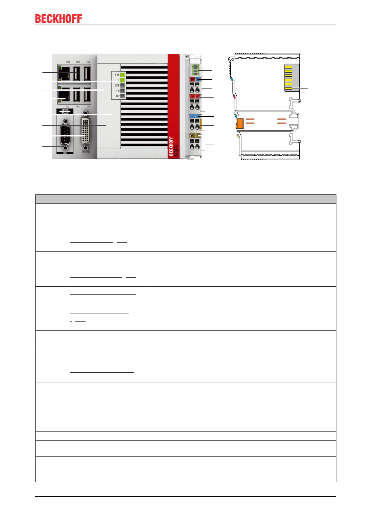
4.1 Configuration of the CX51x0 Embedded PC
Fig.1: Example: CX5140 Embedded PC.
Table3: Legend for the configuration.
No. Component Description
1
2
3
4
5
6
7
8
9
10 Spring-loaded terminals,
11 Terminal bus (K- or E-bus) Interface for EtherCAT Terminals or Bus Terminals. Data exchange
12 Spring-loaded terminal, +24VPower supply for Bus Terminals via power contact.
Optional interface [}24]
(X300).
DVI-I interface [}23]
(X200).
CFast card slot [}38]
(under the front flap).
MicroSD card slot [}37]
(under the front flap).
RJ45 Ethernet interfaces
[}22] (X000, X001).
Battery compartment
[}84] (under the front
flap).
Diagnostic LEDs. [}78]
USB interfaces [}21]
(X100, X101, X102, X103).
Diagnostic LEDs, power
supply terminal. [}79]
+24 V and 0 V
Space for interfaces such as RS232, EtherCAT, CANopen or
others.
The optional interface must be ordered ex factory and cannot be
retrofitted retrospectively.
Interface for a monitor or Panel.
Slot for industrial CFast cards.
Slot for industrial MicroSD cards.
For connecting to local networks or the internet.
Power supply for the battery-backed clock for time and date.
Diagnostic LEDs for power supply, TwinCAT and the optional
interface.
Interfaces for peripherals such as mouse, keyboard or USB
memory.
Diagnosis of the power supply for the Embedded PC and the
Terminal Bus. Status of the E-bus and K-bus communication.
Power supply for Embedded PC.
and supply.
13 Spring-loaded terminal, 0 V Power supply for Bus Terminals via power contact.
14 Terminal release Releases the power supply terminal and therefore the Embedded
PC from the mounting rail.
15 Spring-loaded terminal, PE Spring-loaded terminal for power contact PE.
16 Power contacts, +24 V, 0
V, PE
CX51x0 15Version: 2.7
Power contacts for Bus Terminals.
Page 16
Product overview
1
2
3
6
4
5
7
8
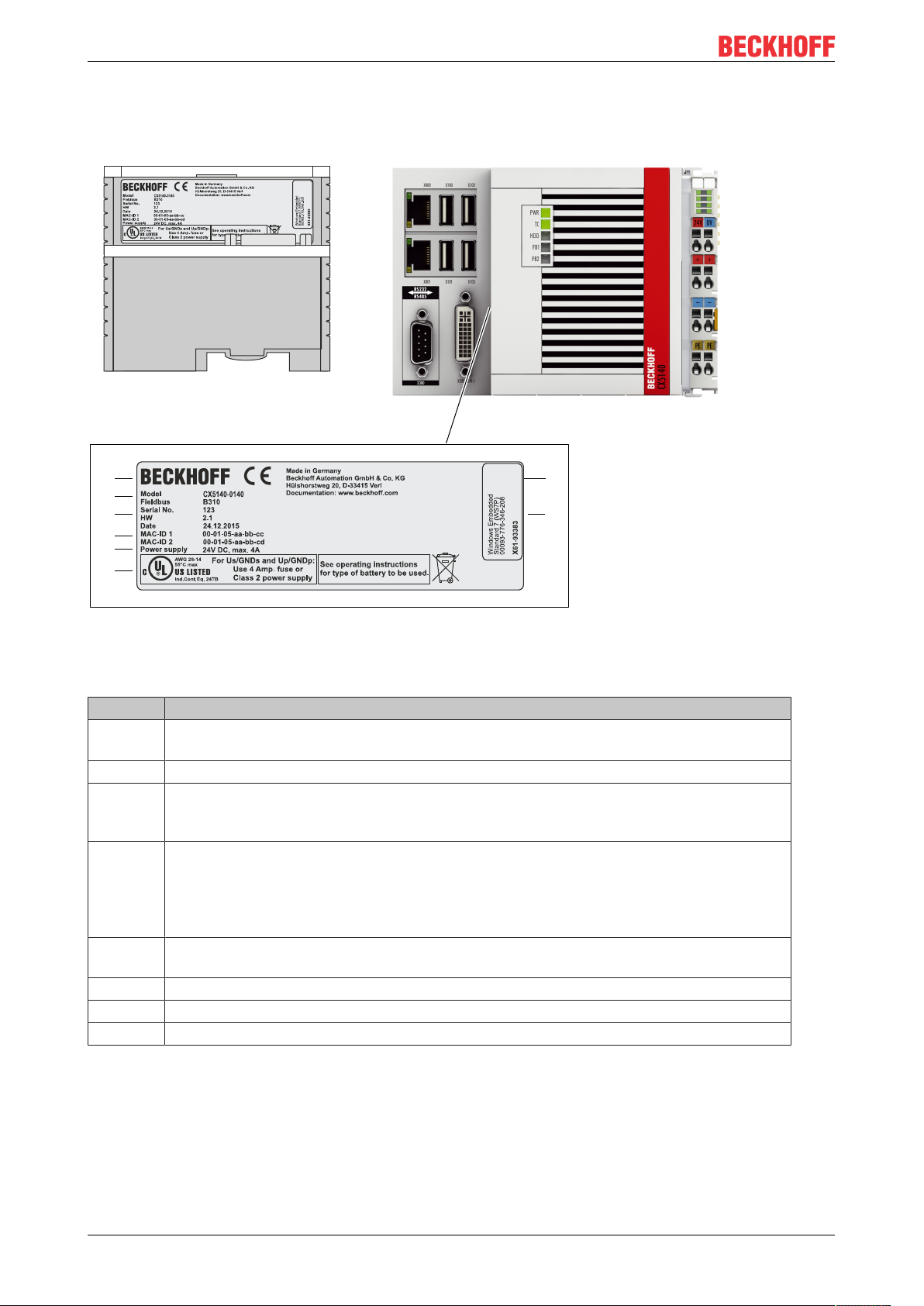
4.2 Name plate
The CX51x0 Embedded PC features a name plate on the left-hand side of the housing.
Fig.2: CX51x0 name plate.
Table4: Legend for the name plate.
No. Description
1 UL approval with prescribed information on power supply, fuse, temperature and cable
cross-sections.
2 Information on the power supply unit. 24 V DC, 4 A max.
3 MAC addresses of the integrated Ethernet ports.
By default, the host name is formed from "CX-" plus the last 3 bytes of the MAC address:
Example: the host name CX-aabbcc is formed from the MAC address 00-01-05-aa-bb-cc.
4 Information on:
• serial number,
• hardware version
• and date of manufacture.
5 Information on the model. The last four numerals relate to the configuration of Embedded
PC.
6 Manufacturer information including address.
7 CE compliant.
8 Windows license sticker (optional).
CX51x016 Version: 2.7
Page 17
Product overview
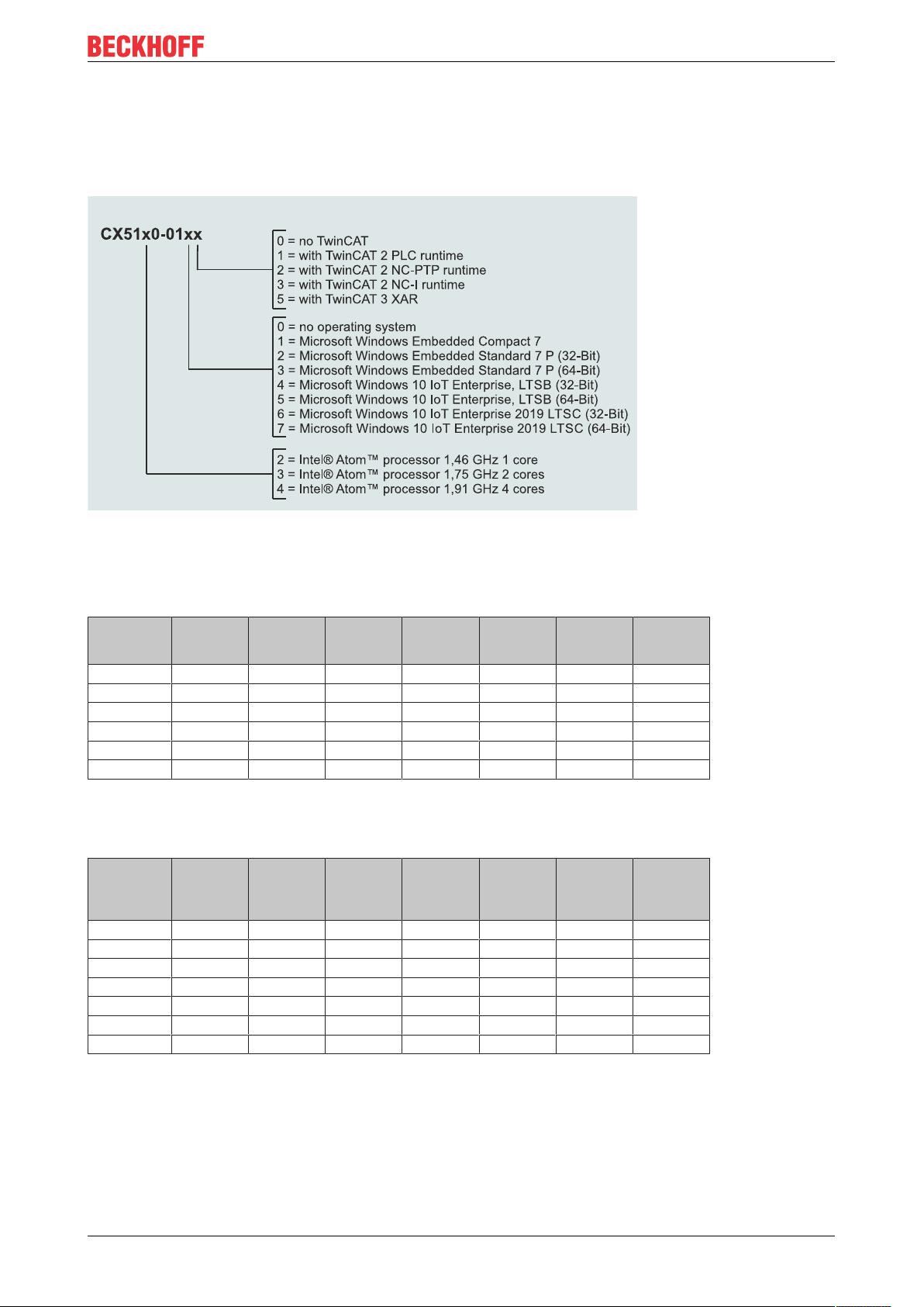
4.3 Types
The CX51x0 Embedded PC can be ordered with different software options. Use this overview in conjunction
with the information on the name plate to ascertain the operating system and the TwinCAT version of the
Embedded PC.
Fig.3: Nomenclature for the CX51x0 Embedded PC.
The Embedded PCs CX5120, CX5130 and CX5140 are available with the following software options:
Table5: Order details, CX51x0 with Windows Embedded Compact 7.
Module no
CX51x0-0100 X - X - - - -
CX51x0-0110 - X
CX51x0-0111 - X
CX51x0-0112 - X
CX51x0-0113 - X
CX51x0-0115 - X
1)
Only one CPU core is supported with Microsoft Windows Embedded Compact 7.
operating
system
Windows
Embedded
Compact 7
1)
1)
1)
1)
1)
no
TwinCAT
TwinCAT 2
PLCRuntime
X - - - -
- X - - -
- - X - -
- - - X -
- - - - X
TwinCAT 2
NC-PTPRuntime
TwinCAT 2
NC-IRuntime
TwinCAT 3
XAR
Table6: Order details, CX51x0 with Windows Embedded Standard 7 P.
Module Windows
Embedded
Standard 7
P (32-bit)
CX51x0-0120 X - X - - - -
CX51x0-0121 X - - X - - -
CX51x0-0122 X - - - X - -
CX51x0-0123 X - - - - X -
CX51x0-0125 X - - - - - X
CX51x0-0130 - X X - - - -
CX51x0-0135 - X - - - - X
Windows
Embedded
Standard 7
P (64-bit)
no
TwinCAT
TwinCAT 2
PLCRuntime
TwinCAT 2
NC-PTPRuntime
TwinCAT 2
NC-IRuntime
TwinCAT 3
XAR
CX51x0 17Version: 2.7
Page 18

Product overview
Table7: Order details, CX51x0 with Windows 10 IoT Enterprise.
Module Windows
10 IoT Enterprise
2016 LTSB
32-bit
CX51x0-0140 X - - - X - - - -
CX51x0-0141 X - - - - X - - -
CX51x0-0142 X - - - - - X - -
CX51x0-0143 X - - - - - - X -
CX51x0-0150 - X - - X - - - -
CX51x0-0155 - X - - - - - - X
CX51x0-0160 - - X - X - - - -
CX51x0-0161 - - X - - X - - -
CX51x0-0162 - - X - - - X - -
CX51x0-0163 - - X - - - - X -
CX51x0-0170 - - - X X - - - -
CX51x0-0175 - - - X - - - - X
Windows
10 IoT Enterprise
2016 LTSB
64-bit
Windows
10 IoT Enterprise
2019 LTSC
32-bit
Windows
10 IoT Enterprise
2019 LTSC
64-bit
no
TwinCAT
TwinCAT 2
PLCRuntime
TwinCAT 2
NC-PTPRuntime
TwinCAT 2
NC-IRuntime
TwinCAT 3
XAR
A CX51x0 Embedded PC with Windows Embedded Compact 7 requires a CFast card with a capacity of at
least 20GB. A CFast card with a capacity of at least 40GB is required for Microsoft Windows Embedded
Standard 7 P and Microsoft Windows 10 IoT Enterprise.
CX51x018 Version: 2.7
Page 19
Product overview
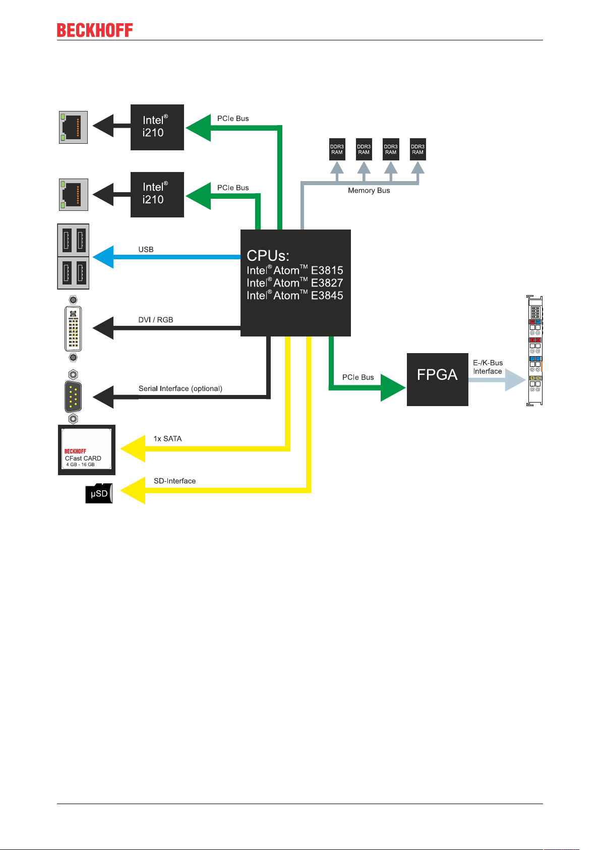
4.4 Architecture overview
The Embedded PCs of the CX51x0 family all have the same architecture. This is described below.
The CX51x0 Embedded PCs are based on the Intel Atom microarchitecture, which was developed by Intel.
The following CPUs are used:
• Intel®AtomTM E3815 (Singlecore)
• Intel®AtomTM E3827 (Dualcore)
• Intel®AtomTM E3845 (Quadcore)
In addition to the arithmetic unit, the CPU also contains the memory controller and the graphics controller.
The processors use the Intel® HD Graphics core. For details on the CPUs please refer to Intel. The memory
is connected directly to the CPU. The Embedded PCs are available in two memory configurations: 2GB or
4GB DDR3 RAM. The memory is not extendable and must be ordered ex factory.
The CPU provides all required interfaces:
• 1 PCI lane for each of the two Intel® i210 Gigabit Ethernet controllers
• 4x USB 2.0 (interfaces)
• DVI-I and DVI-D interface (2nd interface optional in CX51x0-N010)
• Serial interface (CX51x0-N03x)
• 1 PCIe for FPGA for K-/E-bus and NOV-RAM
• 1 SATA for CFast card interface
• 1 IDE for MicroSD card interface
CX51x0 19Version: 2.7
Page 20

Product overview
The interfaces (USB, DVI, and LAN) are standard interfaces. Devices that meet the corresponding standard
can be connected to and operated at these interfaces. A VGA monitor can be connected to the DVI-I
interface with an adapter.
Intel® i210 Gigabit Ethernet controllers are used as network controllers. There are two independent Ethernet
interfaces. Both LAN interfaces are gigabit-capable.
CX51x020 Version: 2.7
Page 21
Description of the interfaces
5 Description of the interfaces
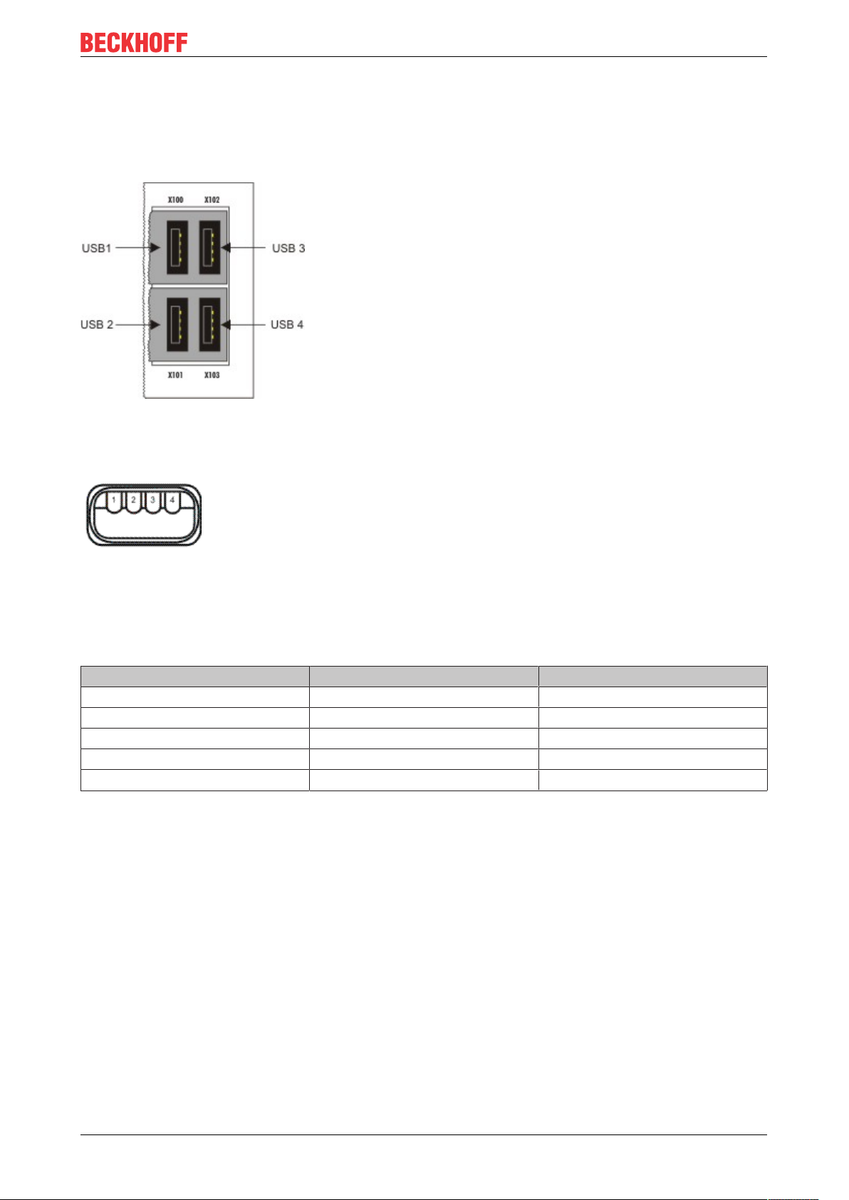
5.1 USB (X100, X101, X102, X103)
Fig.4: USB interfaces (X100, X101, X102, X103).
The Embedded PC has four independent USB interfaces for connecting keyboards, mice, touchscreens and
other input or data storage devices.
Fig.5: USB interface, pin numbering.
Note the power consumption of the individual devices. Each interface is limited to 500mA. The USB
interface is of type A and corresponds to the USB 2.0 specification.
Table8: USB interfaces (X100, X101, X102, X103), pin assignment.
Pin Assignment Typical assignment
1 VBUS Red
2 D- White
3 D+ Green
4 GND Black
Shell Shield Drain Wire
CX51x0 21Version: 2.7
Page 22
Description of the interfaces
X000
X001
LAN 1
LAN 2
LINK / ACT 2
SPEED 2
LINK / ACT 1
SPEED 1
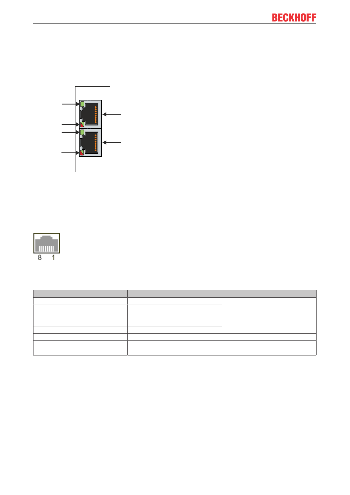
5.2 Ethernet RJ45 (X000, X001)
The two Ethernet interfaces are independent; no switch is integrated. The independent Ethernet interfaces
can be configured in different ways. In delivery state the Ethernet interfaces (X000, X001) are configured for
EtherCAT communication.
Note that an additional switch is required for a line topology.
Fig.6: Ethernet interface X000, X001.
Both Ethernet interfaces reach speeds of 10 / 100 / 1000 Mbit. The LEDs on the left of the interfaces indicate
the connection status. The upper LED (LINK/ACT) indicates whether the interface is connected to a network.
If this is the case the LED is green. The LED flashes when data transfer is in progress.
The lower LED (SPEED) indicates the connection speed. The LED does not light up if the speed is 10 Mbit.
The LED is green if the speed is 100 Mbit. The LED lights up red if the speed is 1000 Mbit (gigabit).
Fig.7: Ethernet interface, pin numbering.
Table9: Ethernet interface X000 and X001, pin assignment.
PIN Signal Description
1 T2 + Pair 2
2 T2 -
3 T3 + Pair 3
4 T1 + Pair 1
5 T1 -
6 T3 - Pair 3
7 T4 + Pair 4
8 T4 -
CX51x022 Version: 2.7
Page 23

Description of the interfaces
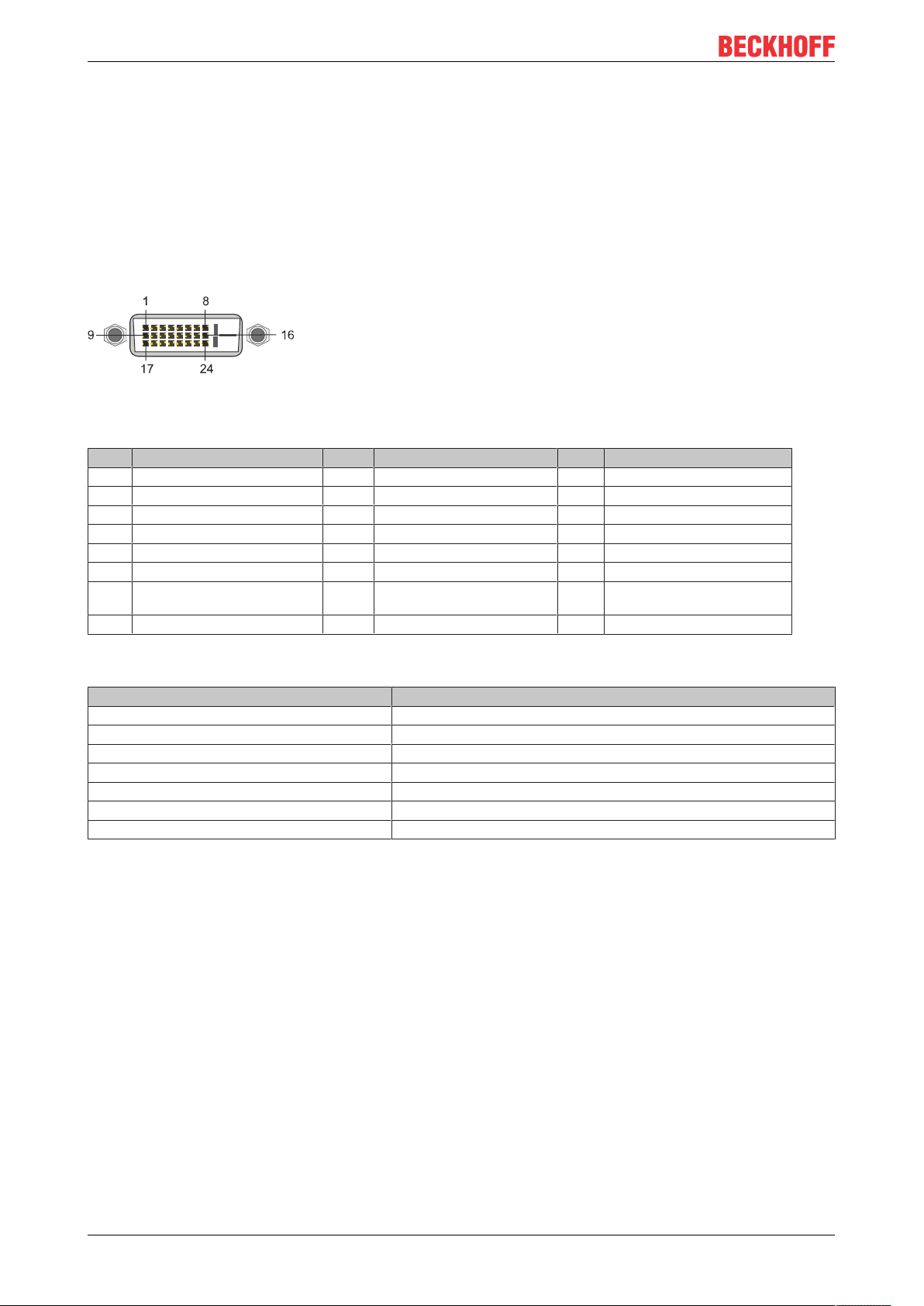
5.3 DVI-I (X200)
The DVI-I interface (X200) transfers digital data and is suitable for connection to digital or analog monitors.
The resolution at the display or the Beckhoff Control Panel depends on the distance from the display device.
The maximum distance is 5 m. Beckhoff offers various Panels with an integrated “DVI extension”. These
make a cable length of up to 50 meters possible.
Fig.8: DVI-I interface X200.
Table10: DVI-I interface X200, pin assignment.
Pin Assignment Pin Assignment Pin Assignment
1 TMDS Data 2- 9 TMDS Data 1- 17 TMDS Data 0-
2 TMDS Data 2+ 10 TMDS Data 1+ 18 TMDS Data 0+
3 TMDS Data 2/4 Shield 11 TMDS Data 1/3 Shield 19 TMDS Data 0/5 Shield
4 not connected 12 not connected 20 not connected
5 not connected 13 not connected 21 not connected
6 DDC Clock 14 + 5V Power 22 TMDS Clock Shield
7 DDC Data 15 Ground ( +5V, Analog H/V
Sync)
8 Analog Vertical Sync 16 Hot Plug Detect 24 TMDA Clock -
23 TMDS Clock +
Table11: DVI-I cross, pin assignment.
Pin Assignment
C1 Analog Red Video Out
C2 Analog Green Video Out
C3 Analog Blue Video Out
C4 Analog Horizontal Sync
Table12: DVI-I interface X200, resolution at the monitor.
Resolution in pixels Distance of the interface from the monitor
1920 x 1200 5 m
1920 x 1080 5 m
1600 x 1200 5 m
1280 x 1024 5 m
1024 x 768 5 m
800 x 600 5 m
640 x 480 5 m
The Embedded PC also supports higher resolutions, based on the DVI standard. A maximum resolution of
2560 x 1440 pixels can be set on the Embedded PC. Whether this resolution is achieved depends on the
monitor, the cable quality and the cable length.
CX51x0 23Version: 2.7
Page 24
Description of the interfaces
5.4 Optional interfaces
5.4.1 DVI-D (N010)
The DVI-D interface (X300) transfers digital data and is suitable for connection to digital displays. If the
optional N010 interface (DVI-D interface) is used, the first DVI-I interface can be operated either in VGA
mode or in DVI mode. The resolution at the display or the Beckhoff Control Panel depends on the distance
from the display device. The maximum distance is 5 m. Beckhoff offers various Panels with an integrated
“DVI extension”. These make a cable length of up to 50 meters possible.
Fig.9: DVI-D interface X300.
Table13: DVI-D interface X300, pin assignment.
Pin Assignment Pin Assignment Pin Assignment
1 TMDS Data 2- 9 TMDS Data 1- 17 TMDS Data 0-
2 TMDS Data 2+ 10 TMDS Data 1+ 18 TMDS Data 0+
3 TMDS Data 2/4 Shield 11 TMDS Data 1/3 Shield 19 TMDS Data 0/5 Shield
4 not connected 12 not connected 20 not connected
5 not connected 13 not connected 21 not connected
6 DDC Clock 14 + 5V Power 22 TMDS Clock Shield
7 DDC Data 15 Ground ( +5V, Analog H/V
Sync)
8 Analog Vertical Sync 16 Hot Plug Detect 24 TMDA Clock -
23 TMDS Clock +
Table14: DVI-D interface X300, resolution at the monitor.
Resolution in pixels Distance of the interface from the monitor
1920 x 1200 5 m
1920 x 1080 5 m
1600 x 1200 5 m
1280 x 1024 5 m
1024 x 768 5 m
800 x 600 5 m
640 x 480 5 m
The Embedded PC also supports higher resolutions, based on the DVI standard. A maximum resolution of
2560 x 1440 pixels can be set on the Embedded PC. Whether this resolution is achieved depends on the
monitor, the cable quality and the cable length.
CX51x024 Version: 2.7
Page 25
Description of the interfaces
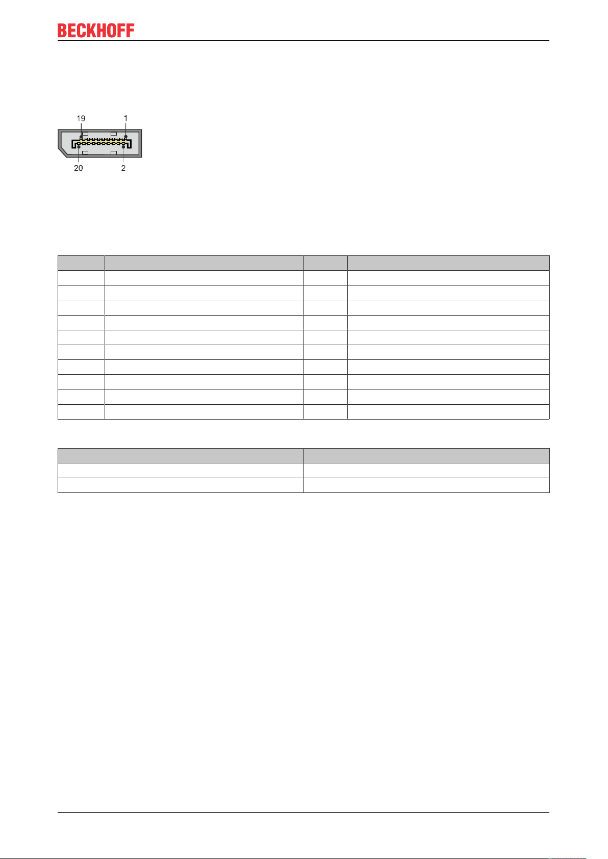
5.4.2 DisplayPort (N011)
The DisplayPort transfers image and audio signal at the same time and is therefore suitable for connecting
panels or monitors to the Embedded PC.
Fig.10: DisplayPort X300.
Version 1.1a of the DisplayPort (DisplayPort++) is installed on the Embedded PC. Adapters from DisplayPort
to DVI-D or DisplayPort to HDMI can be used to connect monitors without DisplayPort to the Embedded PC.
Table15: DisplayPort, pin assignment.
Pin Assignment Pin Assignment
1 LVDS lane 0+ 2 Ground
3 LVDS lane 0- 4 LVDS lane 1+
5 Ground 6 LVDS lane 1-
7 LVDS lane 2+ 8 Ground
9 LVDS lane 2- 10 LVDS lane 3+
11 Ground 12 LVDS lane 3-
13 Config 1 14 Config 2
15 AUX channel+ 16 Ground
17 AUX channel- 18 Hot-plug detection
19 Power supply: ground 20 Power supply: 3.3 V / 500 mA
Table16: DisplayPort X300, resolution at the monitor.
Interface Resolution in pixels
DisplayPort max. 2560 x 1600 @ 60 Hz
DisplayPort with adapter, DisplayPort to DVI-D max. 1600 x 1200 @ 60 Hz
CX51x0 25Version: 2.7
Page 26
Description of the interfaces
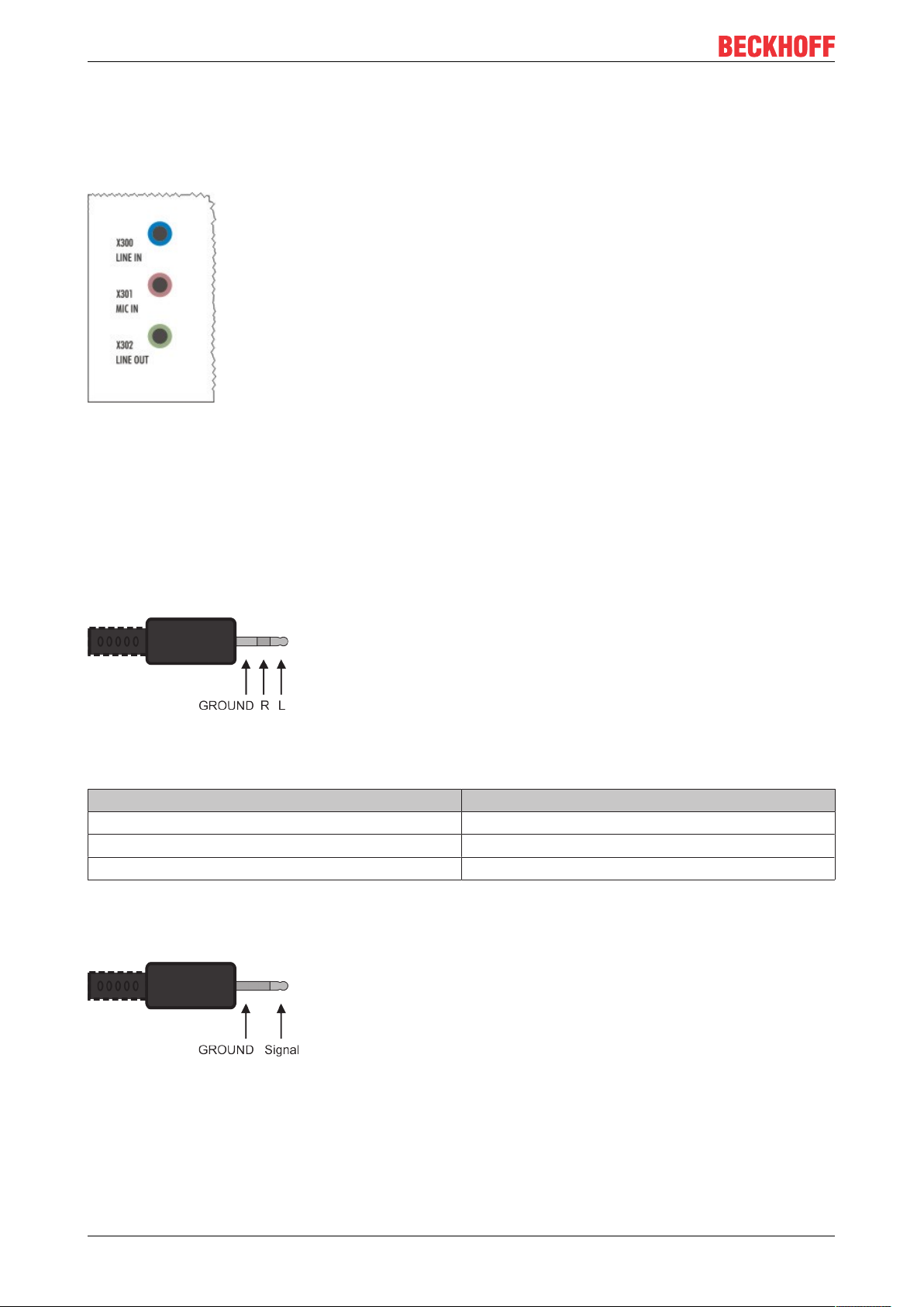
5.4.3 Audio interface (N020)
Two inputs are available: "LINE IN" (X300) and "MIC IN" (X301). The "LINE OUT" interface (X302) is
intended for audio signal output. The 3.5 mm sockets are designed for jack plugs. It can also be used for
connecting headphones with a maximum output of 200 mW.
Fig.11: Audio interface X300, X301, X302.
The audio interfaces are accessed via the operating system.
The audio interface operates in stereo mode as standard, using stereo outputs/inputs and a single-channel
input for the microphone. The inputs should be connected as indicated.
Line In / Line Out jack plugs
The left channel is transferred via the tip of the jack plug, the right channel via the first ring. The remainder of
the sleeve is used for earthing.
Fig.12: Line In / Line Out X300, X302 jack plugs.
Table17: Line In /Line Out jack plugs, pin assignment.
Signal Description
L Left channel
R Right channel
Ground Ground
Mic In jack plug
The only existing channel is transferred via the tip, the remainder of the sleeve is used for earthing.
Fig.13: Mic In X301 jack plug.
CX51x026 Version: 2.7
Page 27

Description of the interfaces
5.4.4 RS232 (N030)
The optional N030 interface provides an RS232 interface (X300). The RS232 interface is implemented on a
9-pin D-sub connector.
Fig.14: RS232 interface X300 with pin numbering.
The maximum baud rate on both channels is 115 kbit. The interface parameters are set via the operating
system or from the PLC program.
Table18: RS232 interface X300, pin assignment.
PIN Signal Type Description
1 - - -
2 RxD Signal in Receive Data
3 TxD Signal out Transmit Data
4 - - -
5 GND Ground Ground
6 - - -
7 RTS Signal out Request to Send
8 CTS Signal in Clear to Send
9 RI Signal in Ring Indicator
Limited driver support
The driver manufacturer does not support all standard functions for the interface. As a result, some
applications may not run properly under Windows.
The following API and IOCTLs are not supported:
• SetupComm
• SetCommBreak
• ClearCommBreak
• EscapeCommFunction (no support for parameters SETBREAK and CLR-BREAK)
• IOCTL_SERIAL_XOFF_COUNTER
• IOCTL_SERIAL_LSRMST_INSERT
• IOCTL_SERIAL_SET_BREAK_ON
• IOCTL_SERIAL_SET_BREAK_OFF
CX51x0 27Version: 2.7
Page 28

Description of the interfaces
5.4.5 RS422/RS485 (N031)
The optional N031 interface provides an RS422 or RS485 interface (X300). The interface is implemented on
a 9-pin D-sub connector.
Fig.15: RS485 interface X300 with pin numbering.
The maximum baud rate on both channels is 115 kbit. The interface parameters are set via the operating
system or from the PLC program.
Table19: RS422/485 interface, pin assignment.
PIN Signal Type Description
2 TxD+ Data-Out + Transmit 422
3 RxD+ Data-In + Receive 422
5 GND Ground Ground
6 VCC VCC +5 V
7 TxD- Data-Out - Transmit 422
8 RxD- Data-In - Receive 422
For RS485 pins 2 and 3 (data +) must be connected, and pins 7 and 8 (data –).
By default the interface is parameterized as follows on delivery:
Table20: Default setting, RS485 without echo with end point (terminated).
Function Status
Echo on off
Echo off on
Auto send on on
Always send on off
Auto receive on on
Always receive on off
Term on on
Term on On
Other configurations for the RS485 interface
Other configurations for the RS485 interface can be ordered ex factory. The following options are available:
• N031-0001 RS485 with echo, end point (terminated).
• N031-0002 RS485 without echo, stub (without termination).
• N031-0003 RS485 with echo, stub (without termination).
• N031-0004 RS422 full duplex end point (terminated).
An RS485 interface cannot be configured retrospectively and must always be ordered ex factory as required.
Limited driver support
The driver manufacturer does not support all standard functions for the interface. As a result, some
applications may not run properly under Windows.
The following API and IOCTLs are not supported:
CX51x028 Version: 2.7
Page 29

Description of the interfaces
• SetupComm
• SetCommBreak
• ClearCommBreak
• EscapeCommFunction (no support for parameters SETBREAK and CLR-BREAK)
• IOCTL_SERIAL_XOFF_COUNTER
• IOCTL_SERIAL_LSRMST_INSERT
• IOCTL_SERIAL_SET_BREAK_ON
• IOCTL_SERIAL_SET_BREAK_OFF
CX51x0 29Version: 2.7
Page 30

Description of the interfaces
5.4.6 EtherCAT slave (B110)
The latest generation of Embedded PCs can be ordered ex factory with an EtherCAT slave interface (B110).
On the devices the optional B110 interface is referred to as X300.
Fig.16: EtherCAT slave interface X300.
The incoming EtherCAT signal is connected to the upper LAN interface. The lower LAN interface relays the
signal to other EtherCAT slave devices.
Fig.17: EtherCAT slave LAN interface, pin numbering.
Table21: EtherCAT slave interface X300, pin assignment.
PIN Signal Description
1 TD + Transmit +
2 TD - Transmit -
3 RD + Receive +
4 connected reserved
5
6 RD - Receive -
7 connected reserved
8
For the optional EtherCAT slave interface (B110), documentation with further information is available for
download from the Beckhoff website:
https://www.beckhoff.de/german/download/epc.htm?id=71003127100362
Document name
CXxxx0-B110 optional interface EtherCAT slave.
CX51x030 Version: 2.7
Page 31

5.4.7 PROFIBUS (x310)
Description of the interfaces
Pin 6 transfers 5V
pin 5 transfers GND for the active termination resistor. These must never be used for
DC,
other functions, as this can lead to destruction of the device.
Pins 3 and 8 transfer the PROFIBUS signals. These must never be swapped over, as this will prevent
communication.
Fig.18: PROFIBUS interface X310 with pin numbering.
The Profibus bus line is connected via a 9-pin D sub with the following pin assignment:
Table22: PROFIBUS interface X310, pin assignment.
Pin Assignment
1 Shielding
2 not used
3 RxD/TxD-P
4 not used
5 GND
6 +5 V
DC
7 not used
8 RxD/TxD-N
9 not used
Table23: Wire colors of the PROFIBUS line.
PROFIBUS line D sub
B red Pin 3
A green Pin 8
For the optional PROFIBUS interface (x310), documentation with further information is available for
download from the Beckhoff website:
https://www.beckhoff.de/german/download/epc.htm?id=71003127100362
Document name
CXxxx0-x310 optional Profibus interface.
CX51x0 31Version: 2.7
Page 32

Description of the interfaces
5.4.8 CANopen (x510)
Fig.19: CANopen interface X510 with pin numbering.
The CAN bus line is connected via a 9-pin D-sub socket with the following configuration:
Table24: CANopen interface X510, pin assignment.
Pin Assignment
1 not used
2 CAN low (CAN-)
3 CAN ground (internally connected to pin 6)
4 not used
5 Shield
6 CAN ground (internally connected to pin 3)
7 CAN high (CAN+)
8 not used
9 not used
For the optional CANopen interface (x510), documentation with further information is available for download
from the Beckhoff website:
https://www.beckhoff.de/german/download/epc.htm?id=71003127100362
Document name
CXxxx0-x510 optional CANopen interface.
CX51x032 Version: 2.7
Page 33

5.4.9 PROFINET RT (x930)
Fig.20: PROFINET RT interface X300.
Fig.21: PROFINET RT LAN interface, pin numbering.
Table25: PROFINET RT interface, pin assignment.
Description of the interfaces
PIN Signal Description
1 TD + Transmit +
2 TD - Transmit -
3 RD + Receive +
4 connected reserved
5
6 RD - Receive -
7 connected reserved
8
CX51x0 33Version: 2.7
Page 34

Commissioning
6 Commissioning
6.1 Assembly
6.1.1 Note the permissible installation positions
Increased heat generation
The Embedded PC may overheat if the installation position is incorrect or the minimum distances
are not adhered to.
The Embedded PC may only be operated at ambient temperatures of up to 60 °C. Ensure adequate
ventilation. Select a horizontal installation position. Leave at least 30 mm clearance above and below the Embedded PC.
Install the Embedded PC horizontally in the control cabinet on a mounting rail, in order to ensure optimum
heat dissipation.
Note the following specifications for the control cabinet:
• The Embedded PC should only be operated at ambient temperatures between -25 °C and 60 °C.
Measure the temperature below the Embedded PC at a distance of 30 mm to the cooling fins, in order
to determine the ambient temperature correctly.
• Adhere to the minimum distances of 30 mm above and below the Embedded PCs.
• Additional electrical equipment affects the heat generation in the control cabinet. Select a suitable
control cabinet enclosure depending on the application, or ensure that excess heat is dissipated from
the control cabinet.
Correct installation position
The Embedded PC must be installed horizontally on the mounting rail. Ventilation openings are located at
the top and bottom of the housing. This ensures an optimum airflow through the Embedded PC in vertical
direction. In addition, a minimum clearance of 30 mm above and below the Embedded PCs required, in order
to ensure adequate ventilation.
Fig.22: CX51x0 Embedded PC, permitted installation position.
If vibrations and impact occurs in the same direction as the mounting rail, the Embedded PC must be
secured with an additional bracket, in order to prevent it slipping.
CX51x034 Version: 2.7
Page 35

Incorrect installation positions
Fig.23: CX51x0 Embedded PC, invalid installation positions.
Commissioning
CX51x0 35Version: 2.7
Page 36

Commissioning
6.1.2 Attaching on mounting rail
The housing is designed such that the Embedded PC can be pushed against the mounting rail and latched
onto it.
Requirements:
• Mounting rail of type TS35/7.5 or TS35/15 according to DIN EN 60715.
Secure the Embedded PC on the mounting rail as follows:
1. Unlock the latches at the top and bottom.
2. Place the Embedded PC at the front of the mounting rail. Slightly press the Embedded PC onto the
mounting rail until a soft click can be heard and the Embedded PC has latched.
3. Then lock the latches again.
ð You have installed the Embedded PC successfully. Double-check the correct installation and latching of
the Embedded PC on the mounting rail.
CX51x036 Version: 2.7
Page 37

Commissioning
6.1.3 MicroSD card installation and removal
Loss of data
MicroSD cards are subjected to heavy load during operation and have to withstand many write cycles and extreme ambient conditions. MicroSD cards from other manufacturer may fail, resulting in
data loss.
Only use industrial MicroSD cards provided by Beckhoff.
The MicroSD card slot is intended for a MicroSD card. Data and further programs can be stored here, or
Windows Embedded Compact 7 can be installed instead.
The eject mechanism is based on the push/push principle. The installation and removal of a MicroSD card is
described below.
Requirements:
• The Embedded PC must be switched off. The MicroSD card may only be installed or removed in
switched-off state.
Removing the MicroSD card
1. Gently push the MicroSD card.
A soft click can be heard when the card is released.
2. The card is lifted by approx. 2-3 mm from the housing. Pull out the card.
Installing a MicroSD card
1. Push the MicroSD card into the Micro SD card slot.
2. A soft click can be heard when the MicroSD card engages.
ð The card is positioned correctly, if it is located approx. 1 mm lower than the front of the housing.
CX51x0 37Version: 2.7
Page 38

Commissioning
6.1.4 CFast card installation and removal
Loss of data
CFast cards are subjected to heavy load during operation and have to withstand many write cycles
and extreme ambient conditions. CFast cards from other manufacturer may fail, resulting in data
loss.
Only use industrial CFast cards provided by Beckhoff.
A CFast card is a non-volatile memory. Data to be retained in the event of a power failure should be saved
on the CFast card. The CFast cards supplied by Beckhoff are industrial cards with an increased number of
write cycles and an extended temperature range (+85 °C).
The eject mechanism is based on the push/push principle. The installation and removal of CFast cards is
described below.
Requirements:
• The Embedded PC must be switched off. The CFast cards may only be installed or removed in
switched off state.
Removing a CFast card
1. Gently push the CFast card.
A soft click can be heard when the card is released.
2. The card is lifted by approx. 4 mm from the housing. Pull out the card.
Installing a CFast card
1. Push the CFast card into the CFast card slot.
2. A soft click can be heard when the CFast card engages.
ð The card is seated correctly if it is flush with the front side of the device housing.
CX51x038 Version: 2.7
Page 39

Commissioning
6.1.5 Installing passive EtherCAT Terminals
Incorrectly installed passive EtherCAT Terminals
The E-bus signal between an Embedded PC and the EtherCAT Terminals can be impaired due to
incorrectly installed passive EtherCAT Terminals.
Passive EtherCAT Terminals should not be installed directly on the power supply unit.
EtherCAT Terminals that do not take part in active data exchange are referred to as passive terminals.
Passive EtherCAT Terminals have no process image and do not require current from the terminal bus (Ebus).
Passive EtherCAT Terminals (e.g. EL9195) can be detected in TwinCAT. In the tree structure the EtherCAT
Terminal is displayed without process image, and the value in column “E-bus (mA)” does not change,
compared to the preceding EtherCAT Terminal.
Fig.24: Identifying a passive EtherCAT Terminal in TwinCAT.
The entry "Current consumption via E-Bus" in the technical data of an EtherCAT Terminal indicates whether
a particular EtherCAT Terminal requires power from the terminal bus (E-bus).
The following diagram shows the permissible installation of a passive EtherCAT Terminal. The passive
EtherCAT Terminal was not directly attached to the power supply unit.
Fig.25: Passive EtherCAT Terminals, permissible installation.
The following diagram shows the invalid installation of a passive EtherCAT Terminal.
Fig.26: Passive EtherCAT Terminals, invalid installation.
CX51x0 39Version: 2.7
Page 40

Commissioning
1
2
3
4
8
6.2 Connecting the power supply
NOTE
Damage to the Embedded PCs
The Embedded PCs may be damaged during wiring.
• The cables for the power supply should only be connected in de-energized state.
The power supply terminals require an external voltage source, which provides 24 V DC (-15% / +20%). The
power supply terminal must provide 4 A at 24 V, in order to ensure the operation of the Embedded PCs in all
situations.
The cabling of the Embedded PC in the control cabinet must be done in accordance with the standard EN
60204-1:2006 PELV = Protective Extra Low Voltage:
• The "PE" and "0V" conductors of the voltage source for a basic CPU module must be on the same
potential (connected in the control cabinet).
• Standard EN 60204-1:2006, section 6.4.1:b stipulates that one side of the circuit, or a point of the
energy source for this circuit must be connected to the protective earth conductor system.
Connection example
Table26: Legend for the connection example
No. Description
1 The upper spring-loaded terminals (Us) identified with “24 V“ and “0 V“ supply the
Embedded PC and the Terminal Bus (data transfer via K- or E-bus).
2 The spring-loaded terminals (Up) identified as "+", "-" and "PE" supply the Bus Terminals
via the power contacts and the sensors or actuators connected to the Bus Terminals.
Fuse protection
• When dimensioning the fuse for the system voltage (Us), observe the max. power consumption of the
Embedded PC (see: Technical Data [}87]).
• Protect power contacts (Up) with a fuse of max. 10 A (slow blow).
CX51x040 Version: 2.7
Page 41

Commissioning
The cables of an external voltage source are connected to the power supply unit with spring-loaded
terminals.
Table27: Required wire cross-sections and strip lengths.
Conductor cross-section 0,5 ... 2,5 mm
2
AWG 20 ... AWG 14
Strip length 8 ... 9 mm 0.33 inch
The voltage source has been connected to the power supply unit
successfully when the two upper power supply terminal LEDs light up in
green.
• The left LED (Us) indicates the supply of the basic CPU module and
terminal bus.
• The red LED (Up) indicates the Bus Terminal supply via the power
contacts.
NOTE
Interrupting / switching off the power supply
To switch off the Embedded PC, do not disconnect the ground (0 V), because otherwise current may continue to flow via the shielding, depending on the device, and damage the Embedded PC or peripheral devices.
• Always disconnect the 24 V line. Devices connected to the Embedded PC, which have their own power
supply (e.g. a Panel) must have the same potential for "PE" and "0 V" as the Embedded PC have (no
potential difference).
Observe the UL requirements
The CX51x0 Embedded PCs are UL certified. The corresponding UL label can be found on the type plate.
Fig.27: UL label for CX51x0 Embedded PC.
The CX51x0 Embedded PCs can thus be used in areas in which special UL requirements have to be met.
These requirements apply to the system voltage (Us) and to the power contacts (Up). Application areas
without special UL requirements are not affected by UL regulations.
UL requirements
• The Embedded PCs must not be connected to unlimited voltage sources.
• Embedded PCs may only be supplied from a 24 V DC voltage source. The voltage source must be
insulated and protected with a fuse of maximum 4 A (corresponding to UL248).
• Or the power supply must originate from a voltage source that corresponds to NEC class 2. An NEC
class 2 voltage source must not be connected in series or parallel with another NEC class 2 voltage
source.
CX51x0 41Version: 2.7
Page 42

Commissioning
6.3 Switching on
Please ensure that the Embedded PC is fully configured before switching on the Embedded PC.
Switch on the Embedded PC as follows:
1. Ensure that all extension, system and fieldbus modules are connected correctly.
2. Check whether the right installation position was selected.
3. Check whether the Embedded PC is mounted securely on the DIN rail and all required Bus Terminals
are connected.
4. Only then switch on the power supply for the power supply unit.
ð The Embedded PC starts automatically when the external power supply is switched on. The pre-installed
operating system is started and all connected extension, system and fieldbus modules are configured.
6.4 Switching off
Loss of data
If the Embedded PC is switched off during operation, data on the CFast card or other hard disks
may be lost.
Do not disconnect the Embedded PC during operation.
Switch off the Embedded PC as follows:
1. Stop all running programs properly, e.g. the control software on the Embedded PC.
2. Shut down the operating system.
3. Do not switch off the external power supply until all other tasks have been completed, in order to switch
off the Embedded PC.
CX51x042 Version: 2.7
Page 43

Configuration
7 Configuration
7.1 Windows Embedded Compact 7
7.1.1 Setting up the audio interface (N020)
Under Windows Embedded Compact 7, the Beckhoff CX configuration tool can be used for the audio
settings.
Requirements:
• Embedded PC with audio interface.
• Windows Embedded Compact 7.
Proceed as follows:
1. Open the Beckhoff CX configuration tool under Start > Control Panel > CX Configuration.
The Beckhoff CX configuration tool window opens.
2. Click on the Miscellaneous tab.
3. Tick the Enable Audio Device checkbox.
4. Click on Audio Settings and set the volume for input and output via the sliders.
5. Select the input source under Input Select. Only one input source can be active at any one time.
ð Confirm the settings with OK, once you have set up the audio interface.
CX51x0 43Version: 2.7
Page 44

Configuration
7.2 Windows Embedded Standard 7 P
7.2.1 Identification of the Ethernet interfaces (X000, X001)
Network and Sharing Center
In the Network and Sharing Center the Ethernet interfaces (X000, X001) of the CX51x0 Embedded PC are
identified as follows as standard:
• Local Area Connection corresponds to Ethernet interface X000.
• Local Area Connection 2 corresponds to Ethernet interface X001.
Fig.28: Windows 7, Identification of the Ethernet interfaces (X000, X001) in the Network and Sharing
Center.
Device Manager
In the Device Manager the Ethernet interfaces (X000, X001) of the CX51x0 Embedded PC are identified as
follows as standard:
• TwinCAT Intel PCI Ethernet adapter (gigabit) corresponds to the Ethernet interface X000.
• TwinCAT Intel PCI Ethernet adapter (gigabit) #2 corresponds to the Ethernet interface X001.
Fig.29: Windows 7, identification of the Ethernet interfaces (X000, X001) in the device manager.
CX51x044 Version: 2.7
Page 45
Configuration
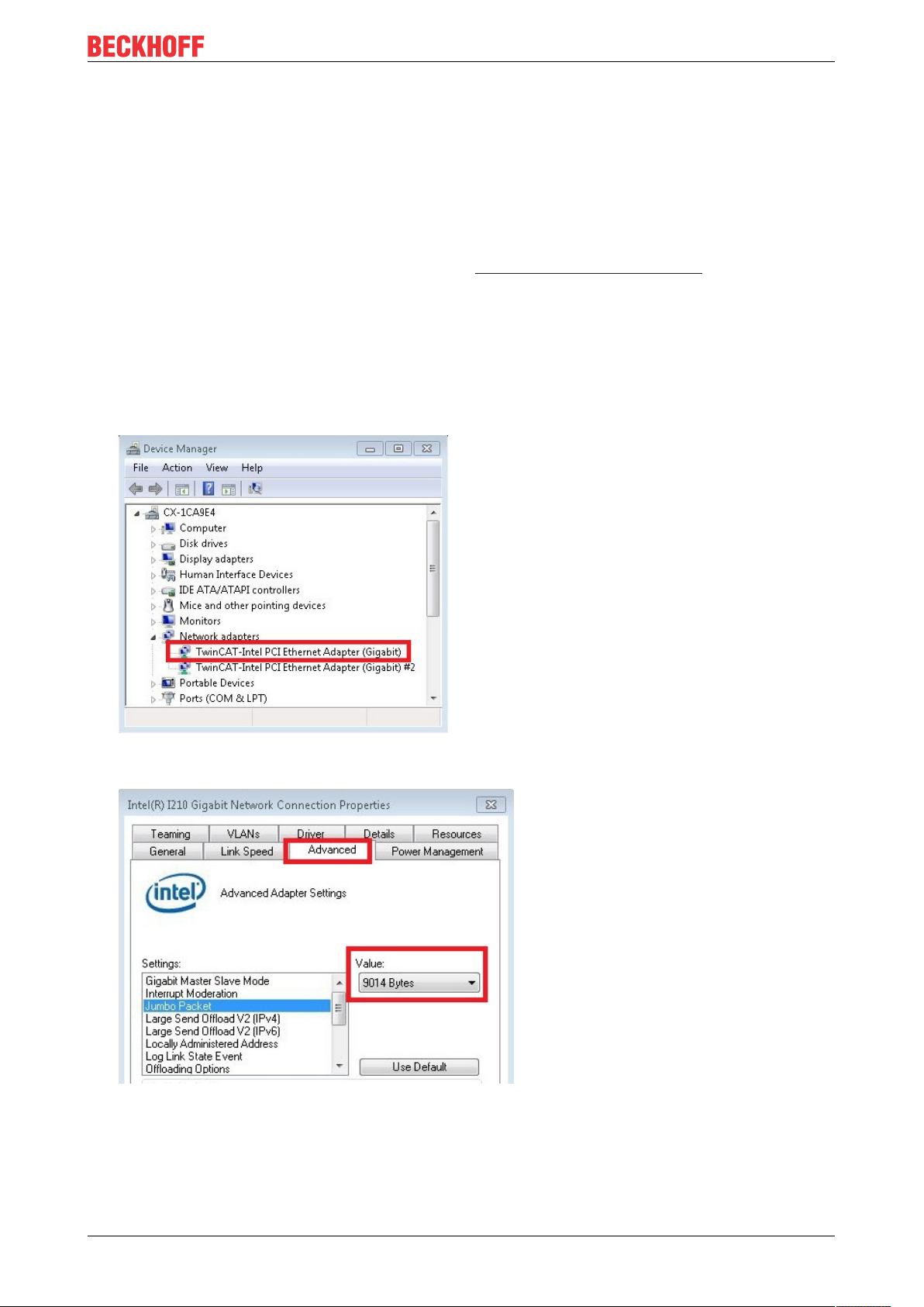
7.2.2 Enabling jumbo frames
Standardized Ethernet frames have a size of 1518 bytes. Ethernet frames that are larger than 1518 bytes
are referred to as jumbo frames. Jumbo frames are used for transferring large data quantities. Jumbo frames
are useful for certain applications, e.g. video cameras.
The Ethernet interfaces (X000, X001) support jumbo frames only if the original Intel® driver is installed.
Requirements:
• The original Intel® driver can be downloaded from https://downloadcenter.intel.com.
• Install the original Intel® driver. Note that this will delete the real-time capable driver from Beckhoff.
• Check whether the peripheral devices support jumbo frames.
Jumbo frames are activated as follows:
1. Under Start > Control Panel > Hardware and Sound click on Device Manager.
2. Double-click on the interface and then on the Advanced tab.
3. Under Settings click on Jumbo Packet, under Value select the option 4088 bytes or 9014 bytes.
ð You have successfully activated jumbo frames, and you can now transfer larger data quantities.
CX51x0 45Version: 2.7
Page 46

Configuration
7.2.3 Set NIC Teaming
NIC Teaming consolidates several physical network cards to group, thereby creating redundancy.
Redundancy can help intercept interference in network cards or in the cabling by assigning the data transfer
to other devices in the group.
Requirements:
• The original Intel® driver can be downloaded from https://downloadcenter.intel.com.
• Install the original Intel® driver for the Network Interface Card. Note that this will delete the real-time
capable driver from Beckhoff.
NIC Teaming is set as follows:
1. Under Start > Control Panel > Hardware and Sound click on Device Manager.
2. Double-click on the interface.
3. Click on the Teaming tab.
4. Click on New Team and follow the installation instructions.
CX51x046 Version: 2.7
Page 47

5. Under Select a team type select the option Adapter Fault Tolerance
Configuration
6. Click on Next to complete the installation.
ð You have successful set NIC Teaming for your Ethernet interfaces. Further settings can be specified or
changed under the Settings tab.
CX51x0 47Version: 2.7
Page 48

Configuration
7.2.4 Restoring the Beckhoff real-time driver.
The Beckhoff real-time driver can be restored if the real-time driver was uninstalled or the original Intel®
driver for jumbo frames or NIC Teaming was installed, for example. This chapter shows you how to use
TcRteInstall.exe to restore the Beckhoff real-time driver. The file is in the TwinCAT directory by default.
Requirements:
• You can find the TcRteInstall.exe in a TwinCAT 2 standard installation under: C:\TwinCAT\Io
\TcRteInstall.exe
• And in a TwinCAT 3 standard installation under: C:\TwinCAT\3.1\System\TcRteInstall.exe
Proceed as follows:
1. Double-click the TcRteInstall.exe file.
The installation dialog appears and shows the compatible Ethernet interfaces under Compatible
devices.
2. Select the Ethernet interfaces for which you wish to restore the Beckhoff real-time driver and click on
Install.
ð The Beckhoff real-time driver is installed. The Ethernet interfaces with installed Beckhoff real-time driver
are shown under Installed and ready to use devices (real-time capable).
CX51x048 Version: 2.7
Page 49

Configuration
7.3 Windows 10 IoT Enterprise LTSB
7.3.1 Identification of the Ethernet interfaces (X000, X001)
Network and Sharing Center
In the Network and Sharing Center the Ethernet interfaces (X000, X001) of the CX51x0 Embedded PC are
identified as follows as standard:
• Ethernet corresponds to the Ethernet interface X000.
• Ethernet 2 corresponds to the Ethernet interface X001.
Fig.30: Windows 10, Identification of the Ethernet interfaces (X000, X001) in the Network and Sharing
Center.
Device Manager
In the Device Manager the Ethernet interfaces (X000, X001) of the CX20x0 Embedded PC are identified as
follows as standard:
• Intel(R) l210 Gigabit Network Connection corresponds to the Ethernet interface X000.
• Intel(R) l210 Gigabit Network Connection #2 corresponds to the Ethernet interface X001.
Fig.31: Windows 10, identification of the Ethernet interfaces (X000, X001) in the device manager.
CX51x0 49Version: 2.7
Page 50

Configuration
7.3.2 Enabling jumbo frames
Standardized Ethernet frames have a size of 1518 bytes. Ethernet frames that are larger than 1518 bytes
are referred to as jumbo frames. Jumbo frames are used for transferring large data quantities. Jumbo frames
are useful for certain applications, e.g. video cameras.
The Ethernet interfaces (X000, X001) support jumbo frames only if the original Intel® driver is installed.
Requirements:
• The original Intel® driver can be downloaded from https://downloadcenter.intel.com.
• Install the original Intel® driver. Note that this will delete the real-time capable driver from Beckhoff.
• Check whether the peripheral devices support jumbo frames.
Jumbo frames are activated as follows:
1. Under Start > Control Panel > Hardware and Sound click on Device Manager.
2. Double-click on the interface and then on the Advanced tab.
3. Under Settings click on Jumbo Packet, under Value select the option 4088 bytes or 9014 bytes.
ð You have successfully activated jumbo frames, and you can now transfer larger data quantities.
CX51x050 Version: 2.7
Page 51

Configuration
7.3.3 Set NIC Teaming
NIC Teaming consolidates several physical network cards to group, thereby creating redundancy.
Redundancy can help intercept interference in network cards or in the cabling by assigning the data transfer
to other devices in the group.
Requirements:
• The original Intel® driver can be downloaded from https://downloadcenter.intel.com.
• Install the original Intel® driver for the Network Interface Card. Note that this will delete the real-time
capable driver from Beckhoff.
NIC Teaming is set as follows:
1. Under Start > Control Panel > Hardware and Sound click on Device Manager.
2. Double-click on the interface.
3. Click on the Teaming tab.
4. Click on New Team and follow the installation instructions.
CX51x0 51Version: 2.7
Page 52

Configuration
5. Under Select a team type select the option Adapter Fault Tolerance
6. Click on Next to complete the installation.
ð You have successful set NIC Teaming for your Ethernet interfaces. Further settings can be specified or
changed under the Settings tab.
CX51x052 Version: 2.7
Page 53

Configuration
7.3.4 Restoring the Beckhoff real-time driver
The Beckhoff real-time driver can be restored if the real-time driver was uninstalled or the original Intel®
driver for jumbo frames or NIC Teaming was installed, for example. This chapter shows you how to use
TcRteInstall.exe to restore the Beckhoff real-time driver. The file is in the TwinCAT directory by default.
Requirements:
• You can find the TcRteInstall.exe in a TwinCAT 2 standard installation under: C:\TwinCAT\Io
\TcRteInstall.exe
• And in a TwinCAT 3 standard installation under: C:\TwinCAT\3.1\System\TcRteInstall.exe
Proceed as follows:
1. Double-click the TcRteInstall.exe file.
The installation dialog appears and shows the compatible Ethernet interfaces under Compatible
devices.
2. Select the Ethernet interfaces for which you wish to restore the Beckhoff real-time driver and click on
Install.
ð The Beckhoff real-time driver is installed. The Ethernet interfaces with installed Beckhoff real-time driver
are shown under Installed and ready to use devices (real-time capable).
CX51x0 53Version: 2.7
Page 54

Configuration
7.3.5 Using serial interfaces N030/N031
With the Embedded PC from the CX5100 series with Windows 10 Image, the serial interfaces are only
supported from a certain BIOS, Image and TwinCAT version onwards.
Table28: System requirements for the operation of the serial interfaces N030 and N031.
Order Option BIOS version Image version TwinCAT version
CX51x0-N030 0.79 CX1800-0501-0011v2.0
CX51x0-N031
The serial interfaces CX51x0-N030 and CX51x0-N031 of the Embedded PC CX51x0 are configured as
standard for operation under TwinCAT. The drivers are not loaded under Windows and you cannot use the
interfaces for custom installed application software.
You can use the interfaces either under Windows 10 or TwinCAT. A mixture of both operating modes is not
possible. The configuration and switching of the operating modes takes place in the BIOS.
Set the BIOS as follows to operate the serial interfaces under Windows 10:
1. Restart the Embedded PC and press [Del] to start the BIOS setup.
The BIOS Setup window appears.
2. Set the option LPSS & SCC Devices Mode to ACPI mode under Advanced > LPSS & SCC
Configuration.
3. Set the option OS Selection to Windows 8.x under Advanced > Miscellaneous Configuration.
4. Press [F4] to save the settings and exit the BIOS setup.
The device is restarted.
CX1800-0511-1011v2.0
2.11.2302
3.1.4022.27
ð After the reboot, the drivers for the serial interfaces are loaded and displayed in the device manager
under Windows 10. The serial interfaces are now ready for operation under Windows 10.
The serial interfaces no longer function under TwinCAT with immediate effect. To operate the serial
interfaces under TwinCAT again, you must restore the default settings in the BIOS setup. Set the options
LPSS & SCC Devices Mode to PCI mode and OS Selection to Windows 7.
CX51x054 Version: 2.7
Page 55

Configuration
7.4 Beckhoff Device Manager
7.4.1 Starting the Beckhoff Device Manager
Using the Beckhoff Device Manager, an Industrial PC can be configured by remote access with the aid of a
web browser. Depending on the image version, access takes place via different protocols and requires
different open ports. For older image versions access takes place via the HTTP protocol and Port 80 (TCP).
More up-to-date image versions use HTTPS and Port 443 (TCP).
Requirements:
• Host PC and Embedded PC must be located in the same network. Depending on the operating system
version, the network firewall must allow access via port 80 (HTTP) or port 443 (HTTPS).
• IP address or host name of the Embedded PC.
Table29: Access data for the Beckhoff Device Manager on delivery.
Operating system Access data
Windows Embedded Standard 7,
Windows 10 IoT Enterprise LTSB
Windows Embedded Compact 7
User name: Administrator
Password: 1
Start the Beckhoff Device Manager as follows:
1. Open a web browser on the host PC.
2. Enter the IP address or the host name of the Industrial PC in the web browser to start the Beckhoff
Device Manager.
• Example with IP address: https://169.254.136.237/config
• Example with host name: https://CX-16C2B8/config
3. Enter the user name and password. The start page appears:
ð Navigate forward in the menu and configure the Industrial PC. Note that modifications only become
active once they have been confirmed. It may be necessary to restart the Industrial PC.
CX51x0 55Version: 2.7
Page 56

Configuration
7.4.2 Enabling a remote display
So that you can remotely access an Industrial PC with CE operating system, you must first activate Remote
Display in the Beckhoff Device Manager. The remote display is disabled by default.
Requirements:
• Host PC and Embedded PC must be located in the same network. Depending on the operating system
version, the network firewall must allow access via port 80 (HTTP) or port 443 (HTTPS).
• The IP address or the host name of the Embedded PC must be known.
Table30: Access data for the Beckhoff Device Manager on delivery.
Operating system Access data
Windows Embedded Compact 7 User name: Administrator
Password: 1
Enable the remote display as follows:
1. Open a web browser on the host PC.
2. Enter the IP address or the host name of the Industrial PC in the web browser to start the Beckhoff
Device Manager.
• Example with IP address: https://169.254.136.237/config
• Example with host name: https://CX-16C2B8/config
3. Enter the user name and password. The start page appears.
4. In the menu under Device click on Boot Opt.
5. Under Remote Display select the option On and confirm the settings.
6. In the information window click OK to accept the settings.
ð You have successfully activated Remote Display on the Industrial PC. After restarting, you can remotely
access your Industrial PC.
CX51x056 Version: 2.7
Page 57

Configuration
7.4.3 Starting a remote connection
With the aid of the Remote Display Control program (CERHOST), a remote connection can be established
and an Industrial PC with CE operating system can be remotely controlled from a host PC.
Requirements:
• Remote Display is active. See: Enabling a remote display.
• Host name of the Embedded PC.
• Remote Display Control (CERHOST). Download under: https://infosys.beckhoff.com/content/1033/
CX51x0_HW/Resources/zip/5047075211.zip
Start the remote connection as follows:
1. Unpack the zip file on the host PC and run cerhost.exe.
2. Click on File in the menu bar and then on Connect.
3. Enter the host name of the Embedded PC in the Hostname field.
ð The remote connection is started and the Windows Embedded CE 7 start screen appears.
CX51x0 57Version: 2.7
Page 58

Configuration
1
6
2
3
7.5 TwinCAT
7.5.1 Tree view
The Tree View chapter can be used as an example for creating a project without actual hardware. All
devices and components of an Embedded PCs must be added manually in TwinCAT 3.
The smallest possible configuration of the CX51x0 Embedded PC is created as follows in the tree view under
TwinCAT 3:
Fig.32: CX51x0 Embedded PC in the tree view of TwinCAT 3, with attached EtherCAT Terminals (left) or
Bus Terminals (right).
The configuration in the tree view differs depending on whether EtherCAT Terminals or Bus Terminals are
connected to the Embedded PC.
Table31: Legend for the tree view.
No. Description
1 The CX51x0 Embedded PC with EtherCAT Terminals is added as
EtherCAT master. Variables for diagnostic purposes are listed under inputs
or outputs.
2 EtherCAT Terminals (E-bus) are displayed under the EK1200 Bus Coupler
in the tree view.
3 If Bus Terminals (K-bus) are used together with an Embedded PC, the Bus
Coupler (CX-BK) is added together with the Bus Terminals.
CX51x058 Version: 2.7
Page 59

Configuration
7.5.2 Searching for target systems
Before you can work with the devices, you must connect your local computer to the target device. Then you
can search for devices with the help of the IP address or the host name.
The local PC and the target devices must be connected to the same network or directly to each other via an
Ethernet cable. In TwinCAT a search can be performed for all devices in this way and project planning
subsequently carried out.
Prerequisites for this step:
• TwinCAT 3 must be in Config mode.
• IP address or host name of the device.
Search for the devices as follows:
1. In the menu at the top click on File > New > Project and create a new TwinCAT XAE project.
2. In the tree view on the left click on SYSTEM, and then Choose Target.
3. Click on Search (Ethernet).
4. Type the host name or the IP address of the device into the Enter Host Name / IP box and press
[Enter].
5. Mark the device found and click on Add Route.
The Logon Information window appears.
CX51x0 59Version: 2.7
Page 60

Configuration
Enter the user name and password for the CX in the User Name and Password fields and click OK.
The following information is set as standard in CX devices:
User name: Administrator Password: 1
6. If you do not wish to search for any further devices, click on Close to close the Add Route Dialog.
The new device is displayed in the Choose Target System window.
7. Select the device you want to specify as target system and click OK.
ð You have successfully searched for a device in TwinCAT and inserted the device as the target system.
The new target system and the host name are displayed in the menu bar.
Using this procedure you can search for all available devices and also switch between the target systems
at any time. Next, you can append the device to the tree view in TwinCAT.
CX51x060 Version: 2.7
Page 61

7.5.3 Scanning an Embedded PC
This step shows how to scan an Embedded PC in TwinCAT and then further configure it.
Prerequisites for this step:
• Selected target device.
Add the Embedded PC as follows:
1. Start TwinCAT and open an empty project.
2. In the tree view on the left, right-click on I/O Devices.
3. In the context menu click on Scan.
Configuration
4. Select the devices you want to use and confirm the selection with OK.
Only devices that are actual available are offered for selection.
For Embedded PCs with connected Bus Terminals (K-bus) a Bus Coupler device (CX-BK) is displayed.
For EtherCAT Terminals (E-bus) the EtherCAT coupler is added automatically.
5. Confirm the request with Yes, in order to look for boxes.
6. Confirm the request whether to enable FreeRun with Yes.
ð The Embedded PC was successfully scanned in TwinCAT and is displayed in the tree view with the
inputs and outputs.
The Tree view chapter illustrates how Embedded PCs with connected Bus or EtherCAT Terminals are
displayed.
CX51x0 61Version: 2.7
Page 62

Configuration
7.5.4 Configure the serial interface (N03x)
This chapter explains how to configure a CX51x0 with serial interface (N03x) in TwinCAT.
The procedure for commissioning the CX51x0-N03x with serial interface under TwinCAT differs from that for
other Embedded PCs. In order to avoid configuration errors, the procedure for adding and configuring the
CX51x0 in TwinCAT is described below.
Prerequisites for this step:
• A scanned and selected target system.
• The description applies to TwinCAT2 from TC2.11.2248 and TwinCAT 3 from TC3.1.4018
Configure the CX51x0-N03x as follows:
1. In the tree view on the left, right-click on Devices.
2. In the context menu click on Scan.
The window new I/O devices found appears.
3. Select the device with a COM port and confirm the selection with OK.
The CX51x0-N03x is added in TwinCAT as Device (COM Port) in the tree view on the left.
4. Click on Device (COM Port) and then on the Serial Port tab.
CX51x062 Version: 2.7
Page 63

5. Under the Serial Port tab, select the option PCI/PCIe Device.
The serial interface of the CX51x0 is shown under Port:.
If the option Onboard/ISA device is already selected, the option PCI/PCIe device is grayed out and
cannot be selected.
Configuration
The option PCI/PCIe device can be re-enabled as follows:
6. Click on Search.
The window Device Found At appears.
7. Click on the COM port, then on OK.
The option PCI/PCIe device is enabled again.
ð You have successfully added and configured the CX51x0 with serial interface (N031x) in TwinCAT. You
can now add further devices to the device and continue with the configuration as usual.
CX51x0 63Version: 2.7
Page 64

Configuration
7.5.5 Configuring EtherCAT cable redundancy.
The Embedded PC has two independent Ethernet interfaces, which can be used for EtherCAT cable
redundancy. Cable redundancy offers resilience for the cabling. Interruptions of the EtherCAT
communication due to broken wires or unplugged LAN cables are avoided.
Fig.33: Smallest possible configuration for EtherCAT cable redundancy.
Interference at the individual terminals is not intercepted by the cable redundancy.
Table32: Cable redundancy, hardware for sample configuration.
Type Description
CX51x0 Embedded PC Is the EtherCAT master in the example.
Bus Coupler EK1110 EtherCAT extension can be used to extend an EtherCAT
segment by up to 100 m.
EK1100 Bus Coupler The Bus Coupler relays the EtherCAT signal to connected
EtherCAT Terminals.
EtherCAT Terminals Any number of EtherCAT Terminals can be connected to
the CX51x0 Embedded PC and the Bus Coupler.
Requirements:
• For TwinCAT 2 you have to install and license the supplement TS622x | TwinCAT EtherCAT
Redundancy on the Embedded PC:
http://www.beckhoff.de/forms/twincat3/warenkorb.aspx?lg=de&title=TS622x-EtherCATRedundancy&version=1.0.2
• In TwinCAT 3 the supplement is already included and only has to be licensed.
• Hardware wired as EtherCAT ring (see Fig.: Smallest possible configuration for EtherCAT cable
redundancy) and added in TwinCAT.
CX51x064 Version: 2.7
Page 65

Configure EtherCAT cable redundancy as follows:
1. In the tree view click on the EtherCAT master.
Configuration
2. Click on the EtherCAT tab, then Advanced Settings.
3. Click on Redundancy in the tree structure on the left.
4. Click on the option Second adapter, followed by the Search button.
CX51x0 65Version: 2.7
Page 66

Configuration
5. Select the appropriate LAN connection according to your cabling at the Embedded PC.
6. Confirm the settings with OK.
ð You have successfully configured cable redundancy. Under the Online tab the EtherCAT slaves are
displayed, for which cable redundancy was configured.
Under State the state of the individual EtherCAT slaves is displayed. If, for example, the cable
connection between the EK1100 and EK1110 Bus Couplers is interrupted, the status of the Bus Coupler
changes. The message "LINK_MIS B" and "LINK_MIS A" appears under status.
Although the connection between the Bus Couplers is interrupted, the EtherCAT Terminals connected to
the EK1100 Bus Coupler show no fault.
If the cable connection is interrupted without cable redundancy at the same location, the terminals show
a fault under status.
7.5.6 Using a hardware watchdog
The function block FB_PcWatchdog_BAPI activates a hardware watchdog on the Embedded PC. The
watchdog can be used to automatically restart systems that have entered an infinite loop or where the PLC
has stopped.
The watchdog is activated with bExecute = TRUE and nWatchdogTimeS >= 1s.
Once the watchdog has been activated, the function block must be called cyclically and at shorter intervals
than nWatchdogTimeS, because the Embedded PC automatically restarts if the set time is less than
nWatchdogTimeS.
CX51x066 Version: 2.7
Page 67

Configuration
NOTE
Unwanted restart
The watchdog restarts the Embedded PC as soon as the time set for nWatchdogTimeS elapses.
Be aware of this behavior and disable the watchdog if you use breakpoints, carry out a PLC reset or an
overall reset, stop TwinCAT, switch to config mode or activate the configuration.
Requirements:
• Tc2_System library.
• TwinCAT v3.1.0
• A previously created PLC project in TwinCAT.
Locating the function block in TwinCAT:
1. Double-click on Tc2_System in the tree view under PLC > PLC project > References.
The Library Manager appears.
2. Under Tc2_System > POUs > SYSTEM +TIME click on the function block FB_PcWatchdog_BAPI.
ð The description of the function block can then be found under the Documentation tab or in the library
description under: FB_PcWatchDog_BAPI. If necessary, you can install the Tc2_System library at a
later stage via the Add Library button in the Library Manager.
CX51x0 67Version: 2.7
Page 68

1-second UPS (persistent data)
8 1-second UPS (persistent data)
Loss of data
The use of the 1-second UPS outside of the documented possibilities can lead to loss or corruption
of data.
Use only TwinCAT to control the 1-second UPS and save only persistent data with a maximum size
of 1 MB.
The 1-second UPS is an UltraCap capacitor that continues to
supply the processor with power in the event of a power failure.
During this period persistent data can be saved, which are
available on switching on again.
Since the 1-second UPS is designed for the entire service life,
the holding time is considerably longer with new devices. The
capacitors age over the course of time and the holding time
decreases. Therefore a maximum of 1MB persistent data can
be reliably saved over the entire service life.
Do not save any other data and do not use any other
applications to control the 1-second UPS.
Please note that the 1-second UPS does not supply power to the K-bus or the E-bus and that their data may
already be invalid when the 1-second UPS is activated. Also, the fieldbus system (or Ethernet) may not work
or not work properly once the 1-second UPS was activated.
Storage location and names of the files:
The persistent data are saved by default in the TwinCAT boot directory:
Development environment File path File name
TwinCAT 2 \\TwinCat\Boot\ TCPLC_T_x.wbp
TwinCAT 3 \\TwinCat\3.1\Boot\Plc Port_85x.bootdata
TCPLC_T_x.wb~ (backup)
The x in the file name stands for the number
of the runtime system.
Port_85x.bootdata-old (backup)
The x in the file name stands for the number
of the runtime system.
Configure the 1-second UPS as follows in order to save persistent data:
• In the case of the CX51x0, check whether the 1-second UPS is activated or deactivated in the BIOS
(see: BIOS settings [}69]). Configure the Windows write filter and issue the corresponding write
permissions in order to be able to save persistent data (see: Windows write filter).
• Declare important data such as counter values in the PLC as VAR PERSISTENT. Then call the
function block FB_S_UPS_CX51x0 cyclically in TwinCAT in order to control the 1-second UPS (see:
FB_S_UPS_CX51x0 [}72]).
• Select the mode in the function block in order to specify what should happen in the case of a voltage
failure. Specify, for example, whether persistent data are saved and a quick shutdown is executed
(see: Mode and status of the function block [}74]).
• Subsequently you can check the validity of the variables and monitor whether the persistent variables
are loaded without error (see: Checking the validity of the variables [}75]).
Sample project:
https://infosys.beckhoff.com/content/1033/CX51x0_HW/Resources/pro/1937303563.pro.
Components Version
TwinCAT on the development PC and on the control system TwinCAT 2.11R3 Build 2047 (or higher)
TwinCAT 3.1 Build 4018 (or higher)
CX51x068 Version: 2.7
Page 69

1-second UPS (persistent data)
8.1 BIOS settings
The CX51x0 family features a built-in capacitive one-second UPS. It ensures a safe storage of the persistent
application data on the Compact Flash card.
Up to 1 MB of persistent data can be saved. The UPS can be switched on and off via the BIOS. Under the
menu:
Advanced -> Power Controller Options
the parameter of the S-UPS are displayed and can be modified, if required.
Aptio Setup Utility - Copyright (C) American Megatrends, Inc.
Bootloader version 1.00-23 WatchDogTimer mode
Firmware version 1.00-77
Mainboard serial no 120003414250178
Mainboard Prod. date (Week.Year) 44.14
Mainboard BootCount 4711
Mainboard operation time 1224min (20h)
Voltage (Min/Max) 5.00V / 5.20V
Temperature (Min/Max) 15°C / 63°C
USB-Port voltage [Off in S3-5]
WatchDogTimerMode [Compatibility mode]
1-second Uninterruptable Power Supply (SUPS) → ←: Select Screen
SUPS Enable [Enable]
Hold Usb [Enable]
Delay 0
SUPS Firmware version 1.09
Current Power source On Line
Battery load level 100%
Powerfail counter 42
↑ ↓: Select Item
Enter: Select
+/-: Change Options
F1: General Help
F2: Previous Values
F3: Optimized Defaults
F4: Save & Exit
ESC: Quit
Version 2.17.1246. Copyright (C) 2014 American Megatrends, Inc.
SUPS Enable
Options: Enable / Disable
Switches the SUPS on or off.
CX51x0 69Version: 2.7
Page 70

1-second UPS (persistent data)
Hold USB
Options: Enable / Disable
Switches off the power supply for the USB ports in UPS mode.
Delay
Options: 0…255 seconds
Start delay with which the SUPS is loaded.
SUPS Firmware Version
Firmware version
Current Power Source
Power supply status: Online / Battery
Battery Load Level
Charge state in percent (n% Cap. (n={0...100}) describes the UPS capacity)
Powerfail Counter
Number of power failures
Integration into a PLC
TwinCAT offers special function blocks for integrating the S-UPS into a PLC program. These are described
below. From TwinCAT 2.11R3 Build 2247 or TwinCAT 3.1 Build 4018 the required library is integrated in the
installation. For older versions the library:
https://infosys.beckhoff.com/content/1033/CX51x0_HW/Resources/rar/1941420683.rar
has to be copied into the TwinCAT library directory.
CX51x070 Version: 2.7
Page 71

1-second UPS (persistent data)
8.2 Windows write filter
Since the persistent data are stored on a storage medium, the file and the path must be writeable. If you use
the Windows write filter, the Windows partition is protected against write access operations, and the
persistent data are not saved.
• Switch off the EWF, if you want to save persistent data.
• The FBWF and UWF do not have to be switched off, because an exception can be defined for the
directory \Boot.
For Windows CE and Windows Embedded Compact 7 no Windows write filters are used.
FBWF exception list
By default an exception list is automatically created when the FBWF is switched on. The \Boot directory is
already entered in this list. Check the configuration of the FBWF if you have made changes to the exception
list.
Fig.34: FBWF exception list, under TwinCAT 2 (left) and TwinCAT 3.
The persistent data are saved by default under \TwinCAT\Boot in TwinCAT 2 and under \TwinCAT\3.1\Boot
in TwinCAT 3.
The FBWF can be configured via the Beckhoff FBWF manager.
UWF exception list
By default an exception list is automatically created when the UWF is switched on. The \Boot directory is
already entered in this list. Check the configuration of the UWF if you have made changes to the exception
list.
Fig.35: UWF exception list under TwinCAT 3
By default, the persistent data are stored under \TwinCAT\3.1\Boot in TwinCAT 3.
The UWF can be configured via the Beckhoff Unified Write Filter Manager.
CX51x0 71Version: 2.7
Page 72

1-second UPS (persistent data)
8.3 FB_S_UPS_CX51x0
Loss of data
The 1-second UPS switches the mainboard off as soon as the capacitors have discharged.
If other applications or the PLC are keeping other data open or are writing to them, data may be
corrupted or lost.
In the case of the CX51x0 the function block FB_S_UPS_CX51x0 is used to control the 1-second UPS from
the PLC. If possible, use the standard values of the FB_S_UPS_CX51x0 and call the function block cyclically
in the PLC.
The function block has various modes that control the behavior of the Embedded PC when the 1-second
UPS is triggered:
Table33: Block modes.
Mode Function
eSUPS_WrPersistData_Shutdown Writing of the persistent data, followed by
quick shutdown.
eSUPS_WrPersistData_NoShutdown Only writing of the persistent data (no
quick shutdown)
eSUPS_ImmediateShutdown Quick shutdown only (no writing of
persistent data)
eSUPS_CheckPowerStatus Monitoring only (neither writing of the
persistent data nor quick shutdown); data
handling is entirely up to the user.
Regardless of the mode and therefore irrespective of whether data were saved or quick shutdown was
performed, the 1-second UPS switches off the mainboard after discharging of the capacitors, even if the
voltage has returned in the meantime.
VAR_INPUT
VAR_INPUT
sNetID:T_AmsNetId:='';(*''=localnetid*)
iPLCPort:UINT:=0;(*PLCRuntimeSystemforwritingpersistentdata*)
iUPSPort:UINT:=16#588;(*Port for reading Power State of UPS*)
tTimeout:TIME:=DEFAULT_ADS_TIMEOUT;(*ADSTimeout*)
eUpsMode:E_S_UPS_Mode:=eSUPS_WrPersistData_Shutdown;(*UPSmode(w/
wowritingpersistentdata,w/woshutdown)*)
ePersistentMode:E_PersistentMode:=SPDM_2PASS;(*modeforwritingpersistentdata*)
tRecoverTime:TIME:=T#10s;(*ONtimetorecoverfromshortpowerfailureinmodeeSUPS_Wr
PersistData_NoShutdown/eSUPS_CheckPowerStatus*)
END_VAR
sNetID: AmsNetID of the controller. (Type: T_AmsNetId)
iPLCPort: Port number of the PLC runtime system.
iUPSPort: Port number via which the UPS status is read (standard value is 16#588).
tTimeout: Timeout for the execution of the quick shutdown.
eUpsMode: The eUpsMode defines whether persistent data are to be written and whether a quick shutdown
is to be performed. Standard value is eSUPS_WrPersistData_Shutdown, i.e. with writing of the persistent
data and then quick shutdown. (Type: E_S_UPS_Mode [}74])
CX51x072 Version: 2.7
Page 73

1-second UPS (persistent data)
ePersistentMode: Mode for the writing of the persistent data. Standard value is SPDM_2PASS.
tRecoverTime: Time after which the UPS reverts to the PowerOK status in the case of UPS modes without
shutdown. The tRecoverTime must be somewhat longer than the maximum holding time of the UPS, since
the UPS switches off even when the voltage returns
VAR_OUTPUT
VAR_OUTPUT
bPowerFailDetect:BOOL;(*TRUEwhilepowerfailureisdetected*)
eState:E_S_UPS_State;(*currentupsstate*)
END_VAR
bPowerFailDetect: TRUE during power failure. FALSE if the supply voltage is present.
eState: Internal state of the function block (type: E_S_UPS_State [}74])
VAR_GLOBAL
VAR_GLOBAL
eGlobalSUpsState:E_S_UPS_State; (*current ups state*)
END_VAR
eGlobalSUpsState: Internal state of the function block as global copy of VAR_OUTPUT
eState: For values see E_S_UPS_State [}74].
Development environment
TwinCAT v2.11 R3 B2246
TwinCAT v3.1 B4016
Target platform Hardware PLC libraries to include
CX51x0 1-Second UPS For TwinCAT 2:
TcSUPS_51x0.lib
For TwinCAT 3: Tc2_SUPS
CX51x0 73Version: 2.7
Page 74

1-second UPS (persistent data)
8.4 Mode and status of the function block
E_S_UPS_Mode
With the mode selected in the function block you can specify what should happen in the case of a power
failure.
eSUPS_WrPersistData_Shutdown:WritingofpersistentdataandthenaQuickShutdown
eSUPS_WrPersistData_NoShutdown:Onlywritingofthepersistentdata(noQuickShutdown)
eSUPS_ImmediateShutdown:OnlyQuickShutdown(nowritingofpersistentdata)
eSUPS_CheckPowerStatus:Onlycheckstatus(neitherwritingofpersistentdatanoraQuickShutdown)
E_S_UPS_State
The internal state of the function block can be read with E_S_UPS_State.
eSUPS_PowerOK:
inallmodes:PowersupplyisOK
eSUPS_PowerFailure:
inallmodes:Powersupplyisfaulty(onlyshownforonePLCcycle)
eSUPS_WritePersistentData:
inmodeeSUPS_WrPersistData_Shutdown:Writingofpersistentdataisactive
inmodeeSUPS_WrPersistData_NoShutdown:Writingofpersistentdataisactive
eSUPS_QuickShutdown:
inmodeeSUPS_WrPersistData_Shutdown:QuickShutdownistactive
inModeeSUPS_ImmediateShutdown:QuickShutdownisactive
eSUPS_WaitForRecover:
inmodeeSUPS_WrPersistData_NoShutdown:Waitforthereestablishmentofthepowersupply
inmodeeSUPS_CheckPowerStatus:Waitforthereestablishmentofthepowersupply
eSUPS_WaitForPowerOFF:
inmodeeSUPS_WrPersistData_Shutdown:WaitforswitchingoffofthePCbytheUPS
inmodeeSUPS_ImmediateShutdown:WaitforswitchingoffofthePCbytheUPS
CX51x074 Version: 2.7
Page 75

1-second UPS (persistent data)
8.5 Checking the validity of the variables
For TwinCAT 2 the implicit structure Systeminfotype.bootDataFlags can be read in order to determine the
validity of the persistent data (see: SYSTEMINFOTYPE [}75]).
For TwinCAT 3 the implicit variables PlcAppSystemInfo.BootDataLoaded and
PlcAppSystemInfo.OldBootData are available for determining the validity of the persistent data (see:
PlcAppSystemInfo [}77]).
8.5.1 SYSTEMINFOTYPE
TYPE SYSTEMINFOTYPE
STRUCT
runTimeNo :BYTE;
projectName :STRING(32);
numberOfTasks :BYTE;
onlineChangeCount :UINT;
bootDataFlags :BYTE;
systemStateFlags :WORD;
END_STRUCT
END_TYPE
runTimeNo: specifies the number of the runtime system (1..4).
projectName: project name as STRING.
numberOfTasks: number of tasks contained in the runtime system (max. 4).
onlineChangeCount: number of online changes since the last complete download.
bootDataFlags: State of the boot data (RETAIN and PERSISTENT) after loading. The upper four bits
indicate the state of the persistent data, while the lower four bits indicate the state of the retain data.
Bit number Description
0 RETAIN variables: LOADED (without error)
1 RETAIN variables: INVALID (the back-up copy was loaded, since no valid data was present)
2 RETAIN variables: REQUESTED (RETAIN variables should be loaded, a setting in TwinCAT
System Control)
3 reserved
4 PERSISTENT variables: LOADED (without error)
5 PERSISTENT variables: INVALID (the back-up copy was loaded, since no valid data was
present)
6 reserved
7 reserved
systemStateFlags : Reserved.
When shutting TwinCAT down the PERSISTENT and RETAIN data is written into two files on the hard disk.
The path can be specified in TwinCAT System Control by means of the TwinCAT system properties (PLC
tab). The standard setting is "<Drive>:\TwinCAT\Boot". The files all have a fixed name with fixed extensions:
File name Description
TCPLC_P_x.wbp Boot project (x = number of the run-time system)
TCPLC_S_x.wbp Packed source code (x = number of the runtime system)
TCPLC_R_x.wbp RETAIN variables (x = number of the runtime system)
TCPLC_T_x.wbp PERSISTENT variables (x = number of the runtime system)
TCPLC_R_x.wb~ Backup copy of the RETAIN variables (x = number of the runtime system)
TCPLC_T_x.wb~ Backup copy of the PERSISTENT variables (x = number of the runtime system)
If the persistent or retain variables are not loaded, e.g. because they are invalid, the backup file is loaded by
default. In that case bit 1 of the bootDataFlags (for the RETAIN variables) in the PLC and/or bit 5 (for the
PERSISTENT variables) is set.
CX51x0 75Version: 2.7
Page 76

1-second UPS (persistent data)
A registry setting can be used to determine whether the backup file is deleted or used. The backup file is
used by default (setting 0). If the backup file is to be deleted, the value of "ClearInvalidRetainData" or
"ClearInvalidPersistentData" must be set to 1 in the registry under:
[HKEY_LOCAL_MACHINE\SOFTWARE\Beckhoff\TwinCAT\Plc]
"ClearInvalidRetainData"=dword:00000000
"ClearInvalidPersistentData"=dword:00000000
the value of "ClearInvalidRetainData" or of "ClearInvalidPersistentData" must be set to 1.
Whether the backup file is to be used can also be set in the TwinCAT System Manager in the tree structure
on the left under PLC > PLC Settings:
The backup files are deleted if the option Clear Invalid Retain Data or Clear Invalid Persistent Data is set
in the System Manager. Corresponds to registry entry 1.
Development environment Target platform PLC libraries to be linked
TwinCAT v2.7.0 PC or CX (x86) PLCSystem.Lib
TwinCAT v2.8.0 PC or CX (x86) TcSystem.Lib
TwinCAT v2.10.0 Build >= 1301 CX (ARM) TcSystem.Lib
CX51x076 Version: 2.7
Page 77

1-second UPS (persistent data)
8.5.2 PlcAppSystemInfo
Each PLC contains an instance of type 'PlcAppSystemInfo' with the name '_AppInfo'.
The corresponding namespace is 'TwinCAT_SystemInfoVarList'. This must be specified for use in a library,
for example.
TYPEPlcAppSystemInfo
STRUCT
ObjId:OTCID;
TaskCnt:UDINT;
OnlineChangeCnt:UDINT;
Flags:DWORD;
AdsPort:UINT;
BootDataLoaded:BOOL;
OldBootData:BOOL;
AppTimestamp:DT;
KeepOutputsOnBP:BOOL;
ShutdownInProgress: BOOL;
LicensesPending: BOOL;
BSODOccured: BOOL;
TComSrvPtr:ITComObjectServer;
AppName:STRING(63);
ProjectName:STRING(63);
END_STRUCT
END_TYPE
ObjId Object ID of the PLC project instance
TaskCnt Number of tasks in the runtime system
OnlineChangeCnt Number of online changes since the last complete download
Flags Reserved
AdsPort ADS port of the PLC application
BootDataLoaded PERSISTENT variables: LOADED (without error)
OldBootData PERSISTENT variables: INVALID (the back-up copy was loaded, since no
valid file was present)
AppTimestamp Time at which the PLC application was compiled
KeepOutputsOnBP The flag can be set and prevents that the outputs are zeroed when a
breakpoint is reached. In this case the task continues to run. Only the
execution of the PLC code is interrupted.
ShutdownInProgress This variable has the value TRUE if a shutdown of the TwinCAT system is in
progress. Some parts of the TwinCAT system may already have been shut
down.
LicensesPending This variable has the value TRUE if not all licenses that are provided by
license dongles have been validated yet.
BSODOccured This variable has the value TRUE if Windows is in a BSOD.
TComSrvPtr Pointer to the TcCOM object server
AppName Name generated by TwinCAT, which contains the port.
ProjectName Name of the project
Differences compared with TwinCAT 2
If the variable runTimeNo was used under TwinCAT 2, the corresponding program code must be converted
for application under TwinCAT 3.
Example:
• Application under TwinCAT 2: nPlcAdsPort := 801 + (SystemInfo.runTimeNo - 1) * 10;
• Application under TwinCAT 3: nPlcAdsPort := _AppInfo.AdsPort;
CX51x0 77Version: 2.7
Page 78

Error handling and diagnostics
9 Error handling and diagnostics
9.1 Diagnostic LEDs
Display LED Meaning
PWR Power supply
The power LED lights green if
the device is connected to a
power supply unit and the unit is
switched on.
The S-UPS is activated (violet).
Bootloader is started and runs
without errors (The colors red
and yellow light up for one
second).
TC TwinCAT status LED
TwinCAT is in Run mode (green)
TwinCAT is in Stop mode (red)
TwinCAT is in Config mode
(blue)
HDD Read/Write CFast card
(red) indicates that access to the
CFast card is in progress.
FB1 Status LED1 for fieldbus (the
function is described under the
fieldbus interface)
FB2 Status LED2 for fieldbus (the
function is described under the
fieldbus interface)
CX51x078 Version: 2.7
Page 79

Error handling and diagnostics
9.2 Power supply terminal LEDs in K-bus mode
The power supply unit checks the connected Bus Terminals for errors. The red LED "K-bus ERR" is off if no
error is present. The red LED "K-bus ERR" flashes if Bus Terminal errors are present.
Display LED Meaning
Us 24 V Power supply for basic CPU module. The LED
lights green if the power supply is correct.
Up 24V Power supply for terminal bus. The LED lights
green if the power supply is correct.
K-BUS RUN Diagnostic K-bus. The green LED lights up in order
to indicate fault-free operation. "Error-free" means
that the communication with the fieldbus system is
also running.
K-BUS ERR Diagnostic K-bus. The red LED flashes to indicate
an error. The red LED blinks with two different
frequencies.
The frequency and number of the flashes can be used to determine the error code and the error argument.
An error is indicated by the "K-bus ERR" LED in a particular order.
Table34: K-bus ERR LED, fault indication sequence through the LED.
Order Meaning
Fast blinking Starting the sequence
First slow sequence Error code
No display Pause, the LED is off
Second slow sequence Error code argument
Count how often the red LED K-bus ERR flashes, in order to determine the error code and the error
argument. In the error argument the number of pulses shows the position of the last Bus Terminal before the
error. Passive Bus Terminals, such as a power feed terminal, are not included in the count.
CX51x0 79Version: 2.7
Page 80

Error handling and diagnostics
Table35: K-BUS ERR LED, fault description and troubleshooting.
Error code Error code argu-
ment
Persistent,
continuous
flashing
3 pulses 0 K-bus command error. • No Bus Terminal inserted.
4 pulses 0 K-bus data error, break
n Break behind Bus
5 pulses n K-bus error in register
6 pulses 0 Error at initialization. Replace Embedded PC.
1 Internal data error. Hardware reset of the Embedded PC
8 Internal data error. Hardware reset of the Embedded PC
7 pulses 0 Process data lengths of
Description Remedy
EMC problems. • Check power supply for undervoltage or
overvoltage peaks.
• Implement EMC measures.
• If a K-bus error is present, it can be
localized by a restart of the power supply
(by switching it off and then on again)
• One of the Bus Terminals is defective;
halve the number of Bus Terminals
attached and check whether the error is
still present with the remaining Bus
Terminals. Repeat this procedure until
the faulty Bus Terminal has been found.
Check whether the Bus End Terminal 9010
behind the power supply
unit.
Terminaln
communication with Bus
Terminal n.
the set and actual
configurations do not
correspond.
is connected.
Check whether Bus Terminal n+1 after the
power supply unit is connected correctly;
replace if necessary.
Replace Bus Terminal at location n.
(switch off and back on again).
(switch off and back on again).
Check the configuration and the Bus
Terminals for consistency.
For some error the LED "K-BUS ERR" does not go out, even if the error was rectified. Switch the power
supply for the power supply unit off and back on again to switch off the LED after the error has been rectified.
State variable
In TwinCAT there is a State variable under the Bus Coupler for K-bus diagnostics.
CX51x080 Version: 2.7
Page 81

Error handling and diagnostics
Fig.36: Status variable for error handling and diagnostics under TwinCAT.
If the value is "0", the K-bus operates synchronous and without error. If the value is <> "0" there may be a
fault, or it may only be an indication that the K-bus cycle is longer than the task. In which case it would no
longer be synchronous with the task. The task time should be faster than 100 ms. We recommend a task
time of less than 50 ms. The K-bus update time typically lies between one and five ms.
Table36: Description of the State variable values.
Bit Description
Bit 0 K-bus error.
Bit 1 Terminal configuration has changed since the start.
Bit 2 Process image lengths do not match.
Bit 8 (still) no valid inputs.
Bit 9 K-bus input update not yet complete.
Bit 10 K-bus output update not yet complete.
Bit 11 Watchdog.
Bit 15 Acyclic K-bus function active (e.g. K-bus reset).
If there is a K-bus error, this can be reset via the IOF_DeviceReset function block (in the TcIoFunctions.lib).
CX51x0 81Version: 2.7
Page 82

Error handling and diagnostics
9.3 Power supply terminal LEDs in E-bus mode
The power supply unit checks the connected EtherCAT Terminals. The "L/A" LED is lit in E-bus mode. The
"L/A" LED flashes during data transfer.
Display LED Meaning
Us 24 V Power supply for basic CPU module.
The LED lights green if the power
supply is correct.
Up 24 V Power supply for terminal bus. The
LED lights green if the power supply
is correct.
L / A off E-bus not connected.
on E-bus connected / no data traffic.
flashes E-bus connected / data traffic on the
E-bus.
CX51x082 Version: 2.7
Page 83

Error handling and diagnostics
9.4 Faults
Please also refer to the Safety instructions section.
Possible faults and their correction
Fault Cause Measures
no function after the Embedded PC
has been switched on
Embedded PC does not boot fully Hard disk damaged (e.g. due to
Computer boots, software starts,
but control does not operate
correctly
µSD card access error Faulty µSD card, faulty card slot Use a different µSD card to check
Embedded PC only works partially
or temporarily
no power supply for the Embedded
PC
other causes
switching off while software is
running), incorrect setup,other
causes
Cause of the fault is either in the
software or in parts of the plant
outside the Embedded PC
Defective components in the
Embedded PC
1. Check fuse
2. Measure voltage at connection,
check plug wiring
Call Beckhoff support
Check setup Call Beckhoff support
Call the manufacturer of the
machine or the software.
the card slot Call Beckhoff support
Call Beckhoff support
Please make a note of the following information before contacting Beckhoff service or support:
1. Precise device ID: CXxxxx-xxxx
2. Serial number
3. Hardware version
4. Any interfaces (N030, N031, B110, ...)
5. TwinCAT version used
6. Any components / software used
The quickest response will come from support / service in your country. Therefore please contact your
regional contact. For details please refer to our website at www.beckhoff.de or ask your distribution partner.
CX51x0 83Version: 2.7
Page 84

Care and maintenance
10 Care and maintenance
10.1 Replace the battery
NOTE
Risk of explosion
An incorrectly inserted battery may explode and damage the Embedded PC.
Only use original batteries and ensure that the positive and negative poles are inserted correctly.
The battery must be replaced every 5 years. Spare batteries can be ordered from Beckhoff Service. A
battery of type CR2032 is used for the Embedded PC.
Table37: Technical data of the battery.
Battery type Electrical properties (at
20°C)
nominal volt-
age
CR2032 3.0 V 225 mAh 0.20 mA 20.0 mm 3.20 mm
The battery compartment is below the front flap. The battery stores the time and date. The time and date are
reset if the battery is removed.
Be aware of this behavior for your hardware and software configuration and reset the time and date in the
BIOS after a battery change. All other BIOS settings remain unchanged and are retained.
Requirements:
• The Embedded PC is switched off.
Replace the battery as follows:
1. Open the front flap.
2. Carefully pull the battery from the bracket.
nominal
capacity
Standard
charge
continuous
load
Dimensions
Diameter Height
3. Push the new battery into the battery compartment. The negative pole points to the left towards the DVI-I
interface.
ð The battery change is complete. Close the front flap and reset the date and time in the BIOS.
CX51x084 Version: 2.7
Page 85

Decommissioning
11 Decommissioning
11.1 Removing cables
NOTE
Electrical voltage
If the power supply is switched on during dismounting, this can lead to damage to the Embedded PCs.
• Switch off the power supply for the Embedded PCs during dismounting.
Cabling
Make a note of the wiring configuration, if you wish to restore it with another device.
Before dismantling the Embedded PC, shut down the Embedded PC and switch off the power supply. Only
then can you remove all the cables. Also remove all cables from the first terminal after the power supply
terminal.
Requirements:
• Exit the software and shut down the Embedded PC.
• Switch off the power supply.
Remove the cables as follows:
1. Remove the cabling from the Embedded PC.
2. Remove the wiring from the first terminal next to the power supply terminal.
3. Pull the orange strap to remove the first terminal after the power supply terminal by pulling it forward.
ð In the next step the Embedded PC can be removed from the DIN rail and dismantled.
CX51x0 85Version: 2.7
Page 86

Decommissioning
11.2 Dismantling the Embedded PC
This chapter explains how to dismantle the Embedded PC and remove it from the mounting rail.
Requirements:
• All cables were removed from the Embedded PC.
Dismantle the Embedded PC as follows:
1. Release the DIN rail mounting by pushing the latches outwards with a screwdriver.
2. Pull the orange strap on the power supply terminal and gently remove the device from the DIN rail.
ð You have removed the Embedded PC successfully.
Disposal
The device must be fully dismantled in order to dispose of it. Electronic components must be disposed of
according to national electronic waste regulations.
CX51x086 Version: 2.7
Page 87

Technical data
12 Technical data
Table38: Technical data, dimensions and weights.
CX5120 CX5130 CX5140
Dimensions (WxHxD) 123 mm x 100 mm x 91
mm
Weight approx. 975 g approx. 1095 g approx. 1095 g
Table39: Technical data, general data.
Technical data CX5120 CX5130 CX5140
Processor Intel® Atom™ E3815
1.46 GHz, single-core
Main memory 2 GB DDR3-RAM 4 GB DDR3-RAM 4 GB DDR3-RAM
Flash memory Slot for CFast card (card not included), slot for MicroSD card
Power supply 24 V DC (-15 %/+20 %)
Max. power consumption 11 W 14 W 16 W
Max. power consumption
(with UPS charging)
Dielectric strength 500 V (supply / internal electronics)
Operating system Microsoft Windows Embedded Compact 7
Control software TwinCAT 2 PLC-runtime, NC-PTP runtime, NC-I runtime
Diagnostics LED 1 x power, 1 x TC status, 1 x flash access, 2 x bus status
Clock Internal battery-backed clock for time and date (battery replaceable)
Approvals CE, UL, Ex, IECEx
18 W 20 W 23 W
Microsoft Windows Embedded Standard 7 P
Microsoft Windows 10 IoT Enterprise LTSB
TwinCAT 3
Intel® Atom™ E3827 1.75
GHz, dual-core
142 mm x 100 mm x 91 mm
Intel® Atom™ E3845
1.91 GHz, single-core
Table40: Technical data, I/O terminals.
Technical data Description
I/O connection via power supply terminal (E-bus or K-bus, automatic recognition)
Power supply for I/O
terminals
Power contacts current
loading
Process data on the Kbus
max. number of terminals
(K-bus)
max. number of terminals
(E-bus)
max. 2A
max. 10 A
max. 2048bytes input and 2048bytes output
64 (255 with K-bus extension)
up to 65534 terminals.
CX51x0 87Version: 2.7
Page 88

Technical data
Table41: Technical data, environmental conditions.
Technical data Description
Ambient temperature
during operation
Ambient temperature
during storage
Relative humidity 95% no condensation
Vibration resistance 10 frequency sweeps in 3 axes
Shock resistance 1000 shocks in each direction, in 3 axes
EMC immunity conforms to EN 61000-6-2
EMC emission conforms to EN 61000-6-4
Protection class IP 20
Table42: Technical data, graphic specifications.
-25 °C to +60 °C
-40 °C ... +85 °C
see notes under: Transport and storage [}13]
6Hz<f<58.1Hz displacement 0.15mm, constant amplitude
58.1Hz<f<500Hz acceleration 5g, constant amplitude
conforms to EN 60068-2-6
15 g, 11 ms
conforms to EN 60068-2-27
Technical data CX5120 CX5130 CX5140
Processor graphics Intel® HD graphics Intel® HD graphics Intel® HD graphics
Graphic memory 256 MB (shared memory)
Base clock frequency 400MHz 542MHz 542MHz
max. burst frequency 400MHz 792MHz 792MHz
Shader model 5.0
DirectX 11
OpenGL 4.0
Table43: Technical data, interfaces.
Technical data Description
LAN 2 x RJ 45, 10/100/1000 Mbit/s
USB 4 x USB 2.0 each rated at 500 mA, type A
DVI-I Resolution on the monitor in pixels:
640 x 480 to 1920 x 1200
Table44: Technical data, optional interfaces.
Technical data Description
DVI-D Resolution on the monitor in pixels: 640 x 480 to 1920 x 1200
DisplayPort Resolution on the monitor in pixels: max. 2560x1600
RS232 D-Sub plug, 9-pole
Electrical isolation 500 V
RS422/RS485 D-Sub plug, 9-pole
Electrical isolation 500 V
EtherCAT slave 2 x RJ 45, EtherCAT IN and OUT
100 Mbaud
PROFIBUS D-Sub plug, 9-pole
9.6kbaud to 12Mbaud
CANopen D-Sub plug, 9-pole
10 kbaud to 1,000 kbaud
PROFINET RT 2 x RJ-45 switches
CX51x088 Version: 2.7
Page 89

13 Appendix
13.1 Accessories
Table45: CFast cards
Order number Description
CX2900-0026 20 GB CFast card, 3D flash, extended temperature range
CX2900-0038 40 GB CFast card, 3D flash, extended temperature range
CX2900-0040 80 GB CFast card, 3D flash, extended temperature range
CX2900-0042 160 GB CFast card, 3D flash, extended temperature range
larger capacities on request
Table46: MicroSD cards.
Order number Description
CX1900-0122 512 MByte microSD card
CX1900-0124 1 GByte microSD card
CX1900-0126 2 GByte microSD card
CX1900-0128 4 GByte microSD card
CX1900-0130 8 GByte microSD card
Appendix
larger capacities on request
Table47: Passive DVI-to-VGA adaptor.
Order number Description
CX1900-0101 Passive DVI-to-VGA adaptor for the connection of standard VGA monitors to the
CX system
– feeds out the VGA signals of the DVI-I interface of the CX module
– DVI-A plug, 29-pin (bottom), socket, 15-pin (top)
– Weight: approx. 40 g
– Dimensions (WxHxD): 40x42x15 mm
Table48: Spare battery for CX systems.
Order number Description
CX1900-0102 Battery for CX systems
type CR2032 3V/225 mAh
CX51x0 89Version: 2.7
Page 90

Appendix
13.2 Certifications
All products of the Embedded PC family are CE, UL and EAC certified. Since the product family is
continuously developed further, we are unable to provide a full listing here. The current list of certified
products can be found at www.beckhoff.com.
FCC Approvals for the United States of America
FCC: Federal Communications Commission Radio Frequency Interference Statement
This equipment has been tested and found to comply with the limits for a Class A digital device, pursuant to
Part 15 of the FCC Rules. These limits are designed to provide reasonable protection against harmful
interference when the equipment is operated in a commercial environment. This equipment generates, uses,
and can radiate radio frequency energy and, if not installed and used in accordance with the instruction
manual, may cause harmful interference to radio communications. Operation of this equipment in a
residential area is likely to cause harmful interference in which case the user will be required to correct the
interference at his own expense.
FCC Approval for Canada
FCC: Canadian Notice
This equipment does not exceed the Class A limits for radiated emissions as described in the Radio
Interference Regulations of the Canadian Department of Communications.
CX51x090 Version: 2.7
Page 91

Appendix
13.3 Support and Service
Beckhoff and their partners around the world offer comprehensive support and service, making available fast
and competent assistance with all questions related to Beckhoff products and system solutions.
Beckhoff's branch offices and representatives
Please contact your Beckhoff branch office or representative for local support and service on Beckhoff
products!
The addresses of Beckhoff's branch offices and representatives round the world can be found on her internet
pages:
http://www.beckhoff.com
You will also find further documentation for Beckhoff components there.
Beckhoff Headquarters
Beckhoff Automation GmbH & Co. KG
Huelshorstweg 20
33415 Verl
Germany
Phone: +49(0)5246/963-0
Fax: +49(0)5246/963-198
e-mail: info@beckhoff.com
Beckhoff Support
Support offers you comprehensive technical assistance, helping you not only with the application of
individual Beckhoff products, but also with other, wide-ranging services:
• support
• design, programming and commissioning of complex automation systems
• and extensive training program for Beckhoff system components
Hotline: +49(0)5246/963-157
Fax: +49(0)5246/963-9157
e-mail: support@beckhoff.com
Beckhoff Service
The Beckhoff Service Center supports you in all matters of after-sales service:
• on-site service
• repair service
• spare parts service
• hotline service
Hotline: +49(0)5246/963-460
Fax: +49(0)5246/963-479
e-mail: service@beckhoff.com
CX51x0 91Version: 2.7
Page 92

List of tables
List of tables
Table 1 Dimensions and weight of the individual modules. ...................................................................... 13
Table 2 Available optional interfaces for the CX51x0. .............................................................................. 14
Table 3 Legend for the configuration. ....................................................................................................... 15
Table 4 Legend for the name plate........................................................................................................... 16
Table 5 Order details, CX51x0 with Windows Embedded Compact 7...................................................... 17
Table 6 Order details, CX51x0 with Windows Embedded Standard 7 P. ................................................. 17
Table 7 Order details, CX51x0 with Windows 10 IoT Enterprise.............................................................. 18
Table 8 USB interfaces (X100, X101, X102, X103), pin assignment........................................................ 21
Table 9 Ethernet interface X000 and X001, pin assignment. ................................................................... 22
Table 10 DVI-I interface X200, pin assignment. ......................................................................................... 23
Table 11 DVI-I cross, pin assignment......................................................................................................... 23
Table 12 DVI-I interface X200, resolution at the monitor............................................................................ 23
Table 13 DVI-D interface X300, pin assignment......................................................................................... 24
Table 14 DVI-D interface X300, resolution at the monitor. ......................................................................... 24
Table 15 DisplayPort, pin assignment. ....................................................................................................... 25
Table 16 DisplayPort X300, resolution at the monitor. ............................................................................... 25
Table 17 Line In /Line Out jack plugs, pin assignment. .............................................................................. 26
Table 18 RS232 interface X300, pin assignment. ...................................................................................... 27
Table 19 RS422/485 interface, pin assignment.......................................................................................... 28
Table 20 Default setting, RS485 without echo with end point (terminated). ............................................... 28
Table 21 EtherCAT slave interface X300, pin assignment. ........................................................................ 30
Table 22 PROFIBUS interface X310, pin assignment. ............................................................................... 31
Table 23 Wire colors of the PROFIBUS line............................................................................................... 31
Table 24 CANopen interface X510, pin assignment................................................................................... 32
Table 25 PROFINET RT interface, pin assignment.................................................................................... 33
Table 26 Legend for the connection example............................................................................................. 40
Table 27 Required wire cross-sections and strip lengths. .......................................................................... 41
Table 28 System requirements for the operation of the serial interfaces N030 and N031. ........................ 54
Table 29 Access data for the Beckhoff Device Manager on delivery. ........................................................ 55
Table 30 Access data for the Beckhoff Device Manager on delivery. ........................................................ 56
Table 31 Legend for the tree view. ............................................................................................................. 58
Table 32 Cable redundancy, hardware for sample configuration. .............................................................. 64
Table 33 Block modes. ............................................................................................................................... 72
Table 34 K-bus ERR LED, fault indication sequence through the LED. ..................................................... 79
Table 35 K-BUS ERR LED, fault description and troubleshooting. ............................................................ 80
Table 36 Description of the State variable values. ..................................................................................... 81
Table 37 Technical data of the battery. ...................................................................................................... 84
Table 38 Technical data, dimensions and weights. .................................................................................... 87
Table 39 Technical data, general data. ...................................................................................................... 87
Table 40 Technical data, I/O terminals. ...................................................................................................... 87
Table 41 Technical data, environmental conditions.................................................................................... 88
Table 42 Technical data, graphic specifications. ........................................................................................ 88
Table 43 Technical data, interfaces............................................................................................................ 88
Table 44 Technical data, optional interfaces. ............................................................................................. 88
CX51x092 Version: 2.7
Page 93

List of tables
Table 45 CFast cards ................................................................................................................................. 89
Table 46 MicroSD cards. ............................................................................................................................ 89
Table 47 Passive DVI-to-VGA adaptor. ...................................................................................................... 89
Table 48 Spare battery for CX systems...................................................................................................... 89
CX51x0 93Version: 2.7
Page 94

List of figures
List of figures
Fig. 1 Example: CX5140 Embedded PC. .............................................................................................. 15
Fig. 2 CX51x0 name plate. .................................................................................................................... 16
Fig. 3 Nomenclature for the CX51x0 Embedded PC. ............................................................................ 17
Fig. 4 USB interfaces (X100, X101, X102, X103).................................................................................. 21
Fig. 5 USB interface, pin numbering...................................................................................................... 21
Fig. 6 Ethernet interface X000, X001..................................................................................................... 22
Fig. 7 Ethernet interface, pin numbering................................................................................................ 22
Fig. 8 DVI-I interface X200. ................................................................................................................... 23
Fig. 9 DVI-D interface X300................................................................................................................... 24
Fig. 10 DisplayPort X300. ........................................................................................................................ 25
Fig. 11 Audio interface X300, X301, X302............................................................................................... 26
Fig. 12 Line In / Line Out X300, X302 jack plugs..................................................................................... 26
Fig. 13 Mic In X301 jack plug................................................................................................................... 26
Fig. 14 RS232 interface X300 with pin numbering. ................................................................................. 27
Fig. 15 RS485 interface X300 with pin numbering. ................................................................................. 28
Fig. 16 EtherCAT slave interface X300. .................................................................................................. 30
Fig. 17 EtherCAT slave LAN interface, pin numbering. ........................................................................... 30
Fig. 18 PROFIBUS interface X310 with pin numbering. .......................................................................... 31
Fig. 19 CANopen interface X510 with pin numbering.............................................................................. 32
Fig. 20 PROFINET RT interface X300..................................................................................................... 33
Fig. 21 PROFINET RT LAN interface, pin numbering. ............................................................................ 33
Fig. 22 CX51x0 Embedded PC, permitted installation position. .............................................................. 34
Fig. 23 CX51x0 Embedded PC, invalid installation positions. ................................................................. 35
Fig. 24 Identifying a passive EtherCAT Terminal in TwinCAT................................................................. 39
Fig. 25 Passive EtherCAT Terminals, permissible installation. ............................................................... 39
Fig. 26 Passive EtherCAT Terminals, invalid installation. ....................................................................... 39
Fig. 27 UL label for CX51x0 Embedded PC. ........................................................................................... 41
Fig. 28 Windows 7, Identification of the Ethernet interfaces (X000, X001) in the Network and Sharing
Center. ......................................................................................................................................... 44
Fig. 29 Windows 7, identification of the Ethernet interfaces (X000, X001) in the device manager. ........ 44
Fig. 30 Windows 10, Identification of the Ethernet interfaces (X000, X001) in the Network and Sharing
Center. ......................................................................................................................................... 49
Fig. 31 Windows 10, identification of the Ethernet interfaces (X000, X001) in the device manager. ...... 49
Fig. 32 CX51x0 Embedded PC in the tree view of TwinCAT 3, with attached EtherCAT Terminals
(left) or Bus Terminals (right). ...................................................................................................... 58
Fig. 33 Smallest possible configuration for EtherCAT cable redundancy................................................ 64
Fig. 34 FBWF exception list, under TwinCAT 2 (left) and TwinCAT 3..................................................... 71
Fig. 35 UWF exception list under TwinCAT 3.......................................................................................... 71
Fig. 36 Status variable for error handling and diagnostics under TwinCAT............................................. 81
CX51x094 Version: 2.7
Page 95

Page 96

More Information:
www.beckhoff.com/CX5100
Beckhoff Automation GmbH & Co. KG
Hülshorstweg 20
33415 Verl
Germany
Phone: +49 5246 9630
info@beckhoff.com
www.beckhoff.com
 Loading...