

Page 1
CX50x0 - Hardware Documentation
Version: 1.3
Datum: 2011-05-02
Page 2

Page 3

Table of contents
Table of contents
CX50x0 - Hardware Documentation
1. Foreword 4
Notes on the documentation 4
Safety instructions 4
Documentation issue status 5
2. Product overview 6
Appropiate use 6
System overview 7
CX5010 - Technical data 9
CX5020 - Technical data 10
Configurations 11
Battery compartment 13
Compact Flash slot 14
Compact Flash card 15
3. Second-UPS 16
Overview 16
Function blocks 17
FB_S_UPS 18
FB_NT_QuickShutdown 21
Functions 22
F_GetVersionTcSUPS 22
Datatypes 23
E_S_UPS_Mode 23
E_S_UPS_State 24
4. Assembly and connecting 25
Unpacking, installation and transport 25
Dimensions 26
Assembly on mounting rail 28
Power supply 30
DVI-D connection 32
USB connections 33
LAN connections 34
RS232 connection 35
RS422/RS485 connection 36
5. Operating/Configuration 37
CX50x0 - Hardware Documentation 1
Page 4

Table of contents
EtherCAT cabel redundancy 37
Switching on / off 41
BIOS Setup 42
Standard CMOS Features 43
IDE Primary Master 44
IDE Primary Slave 46
Advanced BIOS Features 48
CPU Feature 51
Advanced Chipset Features 52
Integrated Peripherals 53
OnChip IDE Device 54
Onboard Device 55
SuperIO Device 56
USB Device 57
Power Management Setup 58
HPET Powermanagement 59
DTS Powermanagement 60
PnP / PCI Configuration 61
IRQ Resources 62
PC Health Status 63
Frequency / Voltage Control 65
6. Error handling and diagnostics 66
CPU basic moule 66
LED CPU basic module 66
LED K-Bus power supply 67
LEDs K-Bus power supply 69
Faults 70
7. Decomissioning 71
Removal and disposal 71
8. Appendix 73
Accessories 73
Certifications 74
Support and service 75
2 CX50x0 - Hardware Documentation
Page 5

Notes on the documentation
1. Foreword
Notes on the documentation
This description is only intended for the use of trained specialists in control and automation engineering who are
familiar with the applicable national standards.
It is essential that the following notes and explanations are followed when installing and commissioning these
components.
The responsible staff must ensure that the application or use of the products described satisfy all the requirements for
safety, including all the relevant laws, regulations, guidelines and standards.
Disclaimer
The documentation has been prepared with care. The products described are, however, constantly under
development.
For that reason the documentation is not in every case checked for consistency with performance data, standards or
other characteristics.
In the event that it contains technical or editorial errors, we retain the right to make alterations at any time and without
warning.
No claims for the modification of products that have already been supplied may be made on the basis of the data,
diagrams and descriptions in this documentation.
Trademarks
Beckhoff®, TwinCAT®, EtherCAT®, Safety over EtherCAT®, TwinSAFE® and XFC® are registered trademarks of and
licensed by Beckhoff Automation GmbH.
Other designations used in this publication may be trademarks whose use by third parties for their own purposes
could violate the rights of the owners.
Patent Pending
The EtherCAT Technology is covered, including but not limited to the following patent applications and patents:
EP1590927, EP1789857, DE102004044764, DE102007017835
with corresponding applications or registrations in various other countries.
The TwinCAT Technology is covered, including but not limited to the following patent applications and patents:
EP0851348, US6167425 with corresponding applications or registrations in various other countries.
Copyright
© Beckhoff Automation GmbH.
The reproduction, distribution and utilization of this document as well as the communication of its contents to others
without express authorization are prohibited.
Offenders will be held liable for the payment of damages. All rights reserved in the event of the grant of a patent,
utility model or design.
CX50x0 - Hardware Documentation 3
Page 6
Notes on the documentation
Safety instructions
Safety rules
Consider the following safety instructions and descriptions!
Product specific safety instructions are to be found on the following pages or in the areas mounting, wiring,
commissioning etc.
Disclaimer
All the components are supplied in particular hardware and software configurations appropriate for the application.
Modifications to hardware or software configurations other than those described in the documentation are not
permitted, and nullify the liability of Beckhoff Automation GmbH.
Personnel qualification
This description is only intended for the use of trained specialists in control, automation and drive engineering who
are familiar with the applicable national standards.
Description of symbols
The following symbols with a adjoining safety advice or notice are used in this documentation. You have to read the
safety advices carefully and adhere them strictly!
Acute risk of injury!
If you do not adhere the safety advice adjoining this symbol, there is immediate danger to
life and health of individuals!
DANGER
Risk of injury!
If you do not adhere the safety advice adjoining this symbol, there is danger to life and
health of individuals!
WARNING
Hazard to individuals!
If you do not adhere the safety advice adjoining this symbol, there is obvious hazard to
individuals!
CAUTION
Hazard to devices and environment
If you do not adhere the notice adjoining this symbol, there is obvious hazard to materials
and environment.
Attention
Note or pointer
This symbol indicates information that contributes to better understanding.
Note
4 CX50x0 - Hardware Documentation
Page 7

Notes on the documentation
Documentation Issue Status
Version Changes
1.3 Requirements for power supply added
1.2 Changes on temperature range and K-bus diagnosis
1.1 Changes on system interface N031 and DVI resolution
1.0 first release
0.1 preliminary version
CX50x0 - Hardware Documentation 5
Page 8
Notes on the documentation
2. Product overview
Intended use
The CX5010 / CX5020 device series is a modular control system designed for top-hat rail installation. The system is
scalable, so that the required modules can be assembled and installed in the control cabinet or terminal box as
required.
Only switch the PC off after closing the software
Before the Embedded PC is switched off, the software currently running on it should be stopped properly in order to
avoid data loss on the hard disk. Please read the section on “Switching off”.
Switch off all system components and uncouple the Industrial PC from the system if the PC is not used for control
purposes, e.g. during a function test. To disconnect first pull the first terminal behind the power supply unit (optional),
then pull the connectors of the fieldbus connections.
System components that have been switched off must be secured against being switched on again.
The Embedded PC’s power supply unit must be supplied with 24 V
Damage to the environment or devices
Do not exchange any parts when under power! Replacing control components while the
system is live may lead to short circuits or overvoltages, which in turn may damage the
Attention
When components are being fitted or removed, the supply voltage must be switched off.
controller and connected peripherals (terminals, monitors, input devices etc.).
DC
.
Software knowledge
System malfunctions
Requires software knowledge! Each user must be familiar with all the functions of the
software installed on the PC to which he has access.
Attention
6 CX50x0 - Hardware Documentation
Page 9
Notes on the documentation
System Overview
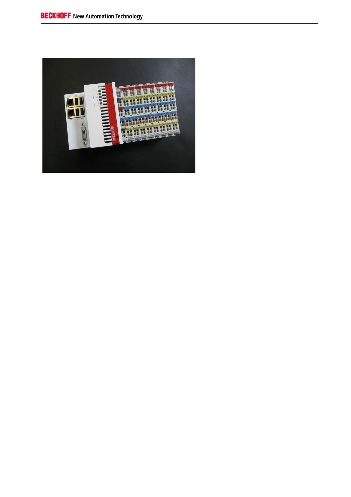
The system
The CX5000 series devices are DIN rail-mountable, fanless Embedded PCs with direct connection for Beckhoff Bus
Terminals or EtherCAT terminals. In contrast to the other CX device families, the CX5000 series has a fixed, nonexpandable number of system interfaces. The housing design for this series is optimised for robustness and
compactness. No modular expandability for the left-hand side is provided. Although EtherCAT integration offers a
wide range of expansion capability. Further master/slave fieldbus connections (PROFIBUS, CANopen, DeviceNet) or
communication interfaces (RS232, RS422/RS485) and all other signal types accessible via EtherCAT can be directly
connected as EtherCAT Terminals. Two independent Gigabit Ethernet ports and four USB 2.0 interfaces are
available. A Beckhoff control panel or a commercially available DVI monitor can be connected to the DVI D interface.
A serial port (RS232/RS422/RS485) or a fieldbus connection with master or slave function can be added as an
optional interface as required. An interchangeable Compact Flash card located behind a flap that is accessible from
outside is used as boot and storage medium. The built-in capacitive 1-second UPS ensures secure backup of
persistent application data on the Compact Flash card. The date and time are buffered via a replaceable battery. The
operating system can be Windows CE or Windows Embedded Standard. The TwinCAT automation software
transforms a CX5000 system into a powerful PLC and motion control system that can be operated with or without
visualisation.
EtherCAT as a fast I/O system
Like all Embedded PCs from the CX series (except CX100x), the CX5000 was developed for optimum interaction
with EtherCAT. One of the two independent Ethernet interfaces of the CPU module (X001) is intended for EtherCAT
mode. The primary EtherCAT connection is generally established via terminals. Both can also be configured as a ring
in order to achieve line redundancy.
Interestingly, EtherCAT offers several options for connecting conventional fieldbus systems to the CX50x0:
As EtherCAT device in terminal form, for example the PROFIBUS master as EtherCAT Terminal EL6731. In practice,
this means that the PROFIBUS master can be positioned exactly where it is required within a machine. It no longer
has to be implemented as a plug-in card in the IPC or a master controller in the control cabinet.
PLC, Motion Control, interpolation and visualisation
As a DIN rail IPC and in conjunction with the TwinCAT software from Beckhoff, the CX50x0 offers the same
functionality as large Industrial PCs. In terms of PLC, up to four virtual IEC 61131 CPUs can be programmed with up
to four tasks each, with a minimum cycle time of 50 μs. All IEC 61131-3 languages can be used.
Moreover, all TwinCAT functionalities are available for Motion Control applications:
In theory, up to 256 axes can be controlled. In addition to simple point-to-point movements, more complex multi-axis
functions such as “electronic gearbox”, “cam plates” and “flying saw” can be implemented.
In addition to real-time execution of control tasks, the TwinCAT real-time kernel ensures that enough time remains for
the user interface (HMI), to communicate with the real-time components via software interfaces such as ADS or OPC.
For CX50x0 the familiar basic principle applies: it is a programming tool for all controllers.
CX50x0 - Hardware Documentation 7
Page 10

Notes on the documentation
The complete programming of PLC, Motion Control and visualisation is transferable to all PC controls from Beckhoff,
which is reassuring in cases where it becomes apparent during a project that more processing power is required after
all. In this case a system with higher performance can be used.
Fieldbus interfaces
The fieldbus interfaces are currently available as master and slave versions for the following field busses:
Optional interfaces:
The optional interfaces can be used to connect single-channel fieldbus interfaces. Operation is limited to one
interface at a time. If several fieldbus interfaces are required, they can be added as E-bus terminals (EL67xx). The
following fieldbus interfaces are available:
CX50x0-N030 = RS232, D-Sub connector
CX50x0-N031 = RS422/RS485, D-Sub socket
CX50x0-M310 = PROFIBUS master, D-Sub socket, 9-pin
CX50x0-B310 = PROFIBUS slave, D-Sub socket, 9-pin
CX50x0-M510 = CANopen master, D-Sub connector, 9-pin
CX50x0-B510 = CANopen slave, D-Sub connector, 9-pin
CX50x0-M930 = PROFINET RT, controller, Ethernet (2 x RJ-45 switch)
CX50x0-B930 = PROFINET RT, device, Ethernet (2 x RJ-45 switch)
CX50x0-B951 = Ethernet/IP slave, Ethernet (2 x RJ-45 switch)
CX50x0-B100 = EtherCAT slave, EtherCAT IN and OUT (2 x RJ 45)
The software
In combination with the TwinCAT automation software, the CX50x0 Industrial PC becomes a powerful IEC 61131-3
PLC with up to four user tasks. Additionally, Motion Control tasks can also be executed. Depending on the required
cycle time, several servo axes can be controlled. Even special functions such as flying saw, electronic gearbox and
cam plate can be realised.
The CX50x0 system is programmed in the same way as other bus controllers:
Remote programming via Ethernet
This option is used if the basic unit is equipped with “Windows CE.NET”. In this case, the system is programmed via
a laptop or a desktop PC, which is connected to the CX via Ethernet (network or crossover cable). The programs are
developed on the laptop with a standard TwinCAT software license and then loaded into the target device.
Visualisation
The Beckhoff OPC server is available for interfacing with SCADA packets, if the two operating system variants
“Windows CE.NET” or “Windows XP Embedded” are used. In other words, the CX50x0 also offers straightforward
visualisation and simultaneous control in real-time on a single system.
8 CX50x0 - Hardware Documentation
Page 11
Notes on the documentation
CX5010 Technical data
The basic configuration of the CX5010 includes a 64 MB Compact Flash card. The basic configuration includes two
Ethernet RJ-45 interfaces, four USB-2.0 interfaces and a DVI-D interface.
Technical data CX5010
Processor Intel® Atom™ Z510 processor, 1.1 GHz clock frequency
Internal Flash memory 64 MB Compact Flash card
Internal main memory 512 MB RAM (interior, not expandable)
Interfaces 2 x RJ 45, 10/100/1000 Mbit/s, DVI-D, 4 x USB 2.0
Diagnostics LED 1 x power, 1 x TC status, 1 x flash access, 2 x bus status
Clock Internal clock with battery backup for time and date (battery replaceable)
Operating system Microsoft Windows CE or Microsoft Windows Embedded Standard
Control software TwinCAT PLC runtime or TwinCAT NC PTP runtime
Power supply 24 V DC (-15 %/+20 %)
Power supply I/O terminals 2 A
Max. power loss 12 W (including system interfaces)
Dielectric strength 500 Veff (supply/internal electronics)
Dimensions (H x W x D) 100 mm x 106 mm x 92 mm
Weight approx. 575 g
Operating/storage temperature -25°C ... +60°C / -40°C ... +85°C
Relative humidity 95 % no condensation
Vibration/shock resistant conforms to EN 60068-2-6/EN 60068-2-27/ 29
EMC immunity/emission conforms to EN 61000-6-2 / EN 61000-6-4
Protection class IP 20
Technical data
Further Information: www.beckhoff.de/CX5010
CX50x0 - Hardware Documentation 9
Page 12
Notes on the documentation
CX5020 - Technical data
The basic configuration of the CX5010 includes a 64 MB Compact Flash card. The basic configuration includes two
Ethernet RJ-45 interfaces, four USB-2.0 interfaces and a DVI-D interface.
Technical data CX5010
Processor Intel® Atom™ Z530 processor, 1.6 GHz clock frequency
Internal Flash memory 64 MB Compact Flash card
Internal main memory 512 MB RAM (interior, not expandable)
Interfaces 2 x RJ 45, 10/100/1000 Mbit/s, DVI-D, 4 x USB 2.0
Diagnostics LED 1 x power, 1 x TC status, 1 x flash access, 2 x bus status
Clock Internal clock with battery backup for time and date (battery replaceable)
Operating system Microsoft Windows CE or Microsoft Windows Embedded Standard
Control software TwinCAT PLC runtime or TwinCAT NC PTP runtime
Power supply 24 V DC (-15 %/+20 %)
Power supply I/O terminals 2 A
Max. power loss 12.5 W (including system interfaces)
Dielectric strength 500 Veff (supply/internal electronics)
Dimensions (H x W x D) 100 mm x 106 mm x 92 mm
Weight approx. 575 g
Operating/storage temperature -25 C ... +60°C / -40 C ... +85°C
Relative humidity 95 % no condensation
Vibration/shock resistant conforms to EN 60068-2-6/EN 60068-2-27/ 29
EMC immunity/emission conforms to EN 61000-6-2 / EN 61000-6-4
Protection class IP 20
Further Information: www.beckhoff.de/CX5020
10 CX50x0 - Hardware Documentation
Page 13
Notes on the documentation
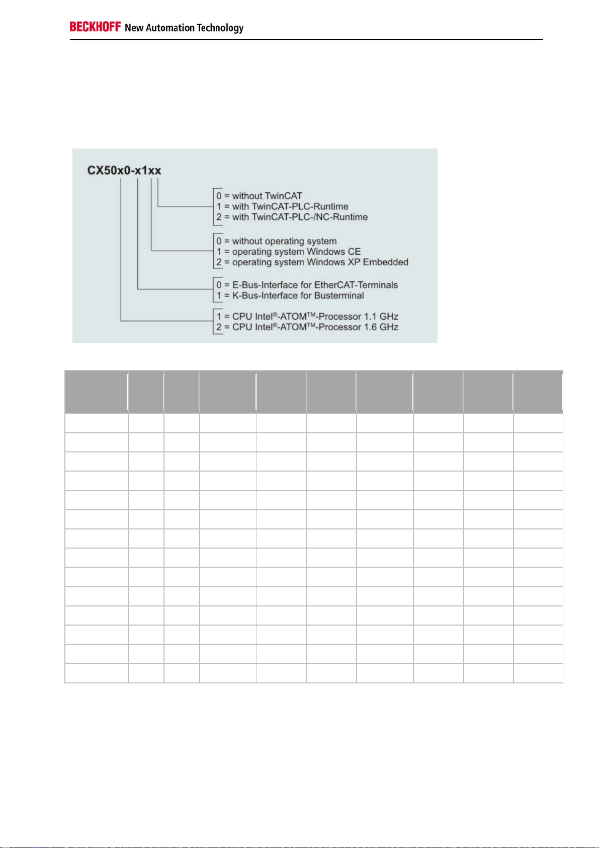
Types
The CPU module can be equipped with different hardware and software options: "Windows CE" or "Windows
Embedded Standard" are available as operating system. The TwinCAT automation software transforms a CX50x0
system into powerful PLC and Motion Control system that can be operated with or without visualisation. Further
system interfaces (pre-installed in the factory) or fieldbus connections can be added to the basic CPU module.
The CX 50x0 modules are available in the following types:
Windows
K-
Modul
CX5020-0100 X 1,6 GHz X - - X - -
CX5020-0110 X 1,6 GHz - X - X - -
CX5020-0111 X 1,6 GHz - X - - X -
CX5020-0112 X 1,6 GHz - X - - - X
CX5020-0120 X 1,6 GHz - - X X - -
CX5020-0121 X 1,6 GHz - - X - X -
CX5020-0122 X 1,6 GHz - - X X - X
CX5020-1100 X - 1,6 GHz X - - X - -
CX5020-1110 X - 1,6 GHz - X - X - -
CX5020-1111 X - 1,6 GHz - X - - X -
CX5020-1112 X - 1,6 GHz - X - - - X
BUS E-BUS
CPUfrequency
without
OS
Windows
CE
Embedded
Standard
without
TwinCAT
TwinCAT
PLC
Runtime
TwinCAT
NC PTP
Runtime
CX5020-1120 X - 1,6 GHz - - X X - -
CX5020-1121 X - 1,6 GHz - - X - X -
CX5020-1122 X - 1,6 GHz - - X X - X
CX50x0 - Hardware Documentation 11
Page 14
Notes on the documentation
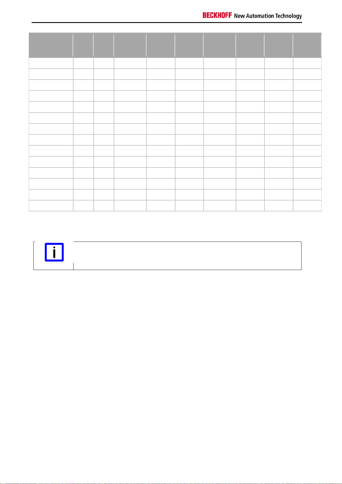
Windows
K-
Modul
CX5020-0100 X 1,6 GHz X - - X - -
CX5020-0110 X 1,6 GHz - X - X - -
CX5020-0111 X 1,6 GHz - X - - X -
CX5020-0112 X 1,6 GHz - X - - - X
CX5020-0120 X 1,6 GHz - - X X - -
CX5020-0121 X 1,6 GHz - - X - X -
CX5020-0122 X 1,6 GHz - - X X - X
CX5020-1100 X - 1,6 GHz X - - X - -
CX5020-1110 X - 1,6 GHz - X - X - -
CX5020-1111 X - 1,6 GHz - X - - X -
CX5020-1112 X - 1,6 GHz - X - - - X
CX5020-1120 X - 1,6 GHz - - X X - -
CX5020-1121 X - 1,6 GHz - - X - X -
BUS E-BUS
CPUfrequency
without
OS
Windows
CE
Embedded
Standard
without
TwinCAT
TwinCAT
PLC
Runtime
TwinCAT
NC PTP
Runtime
CX5020-1122 X - 1,6 GHz - - X X - X
CX50x0 systems with Windows Embedded Standard require a Compact Flash card with a minimum capacity of 2 GB.
Software Images
A list of the different software images can be found in the CX1000 Software Documen-
Note
tation.
12 CX50x0 - Hardware Documentation
Page 15
Notes on the documentation
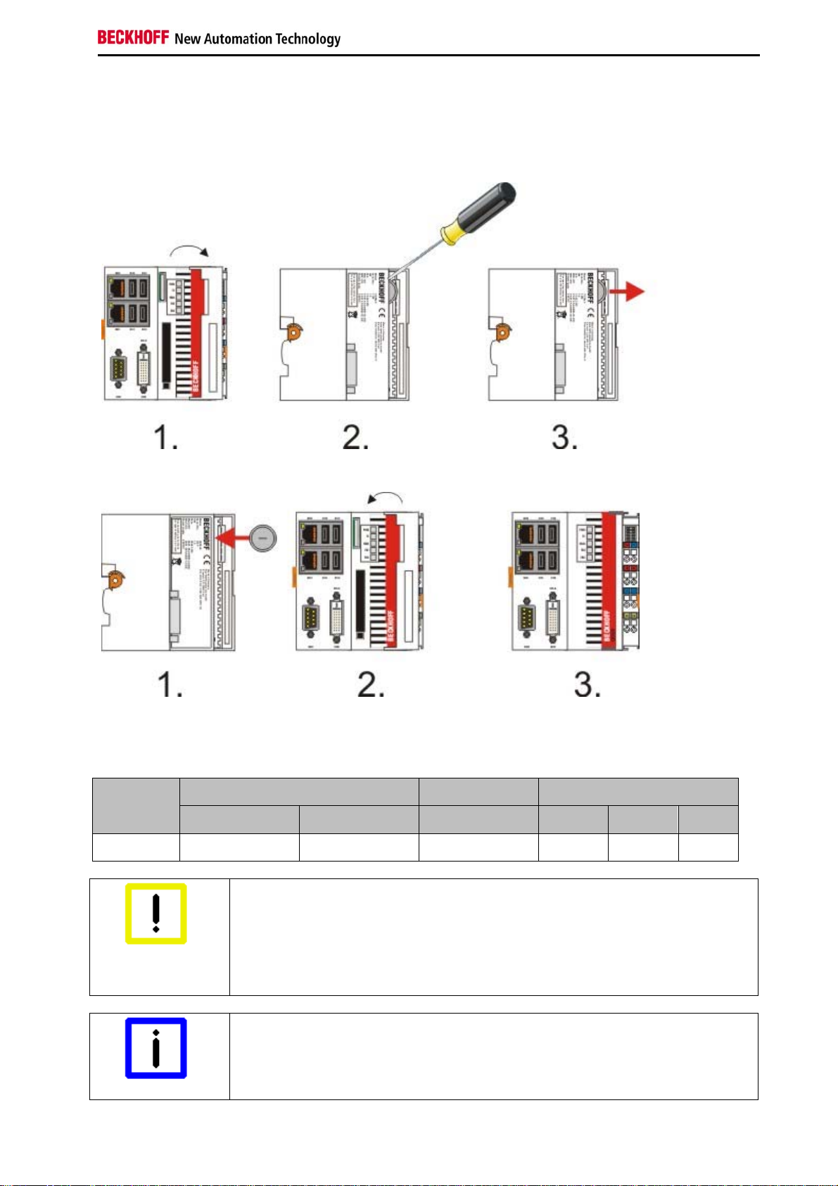
Battery compartment
The battery compartment is located under the front cover of the CX50x0. The opening in which the battery bracket is
mounted can be seen when the front cover is opened. Use a screwdriver to carefully lift the battery out of the bracket.
To insert a new battery push it into the battery compartment. Ensure correct polarity. Then close the front cover. The
battery change is then complete.
The battery is a CR2032 type from Panasonic.
The correct specifications are:
Battery
type
CR2032 3.0 V 225 mAh 0.20 mA 20.0 mm 3.20 mm 3.1 g
Attention
Electrical properties (at 20°C) Standard charge Dimensions
Nominal voltage Nominal capacity Continuous load Diameter Height Wight
An incorrectly inserted battery may explode!
Only use the same battery type (CR2032) from Sanyo or Panasonic.
It is essential that positive and negative terminals of the battery are inserted correctly
(negative pole on the left)
Never open the battery or throw it into a fire.
The battery cannot be recharged.
Battery maintenance
The battery must be replaced every 5 years.
Spare batteries can be ordered from Beckhoff Service
Note
CX50x0 - Hardware Documentation 13
Page 16
Notes on the documentation
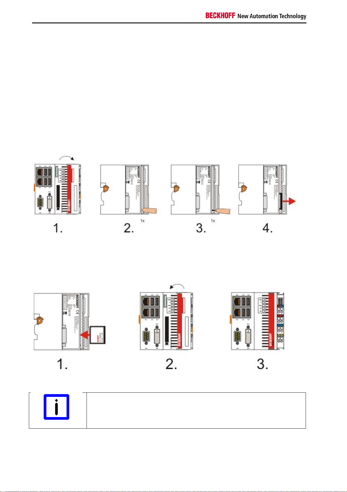
CF slot
A Compact Flash slot is located at the front, which enables the storage medium to be replaced. In the basic module
this should only be done in switched-off state, otherwise the system may crash. The Compact Flash card can be
removed from the module for maintenance. In this way it is also possible to expand the system (only operating
system and program memory). Compact Flash cards (CF cards) are available as accessories in various sizes.
The following images illustrate the handling of the CF cards. Open the front cover. Then eject mechanism and the CF
card slot are then visible. The eject mechanism is based on the push-push principle: If the head of the mechanical
system is retracted, pushing it makes it move out of the housing. Pushing the head again will lock it back in the
housing. At the same time the card moves approx. 4 mm out of the housing, so that it can be pulled out. If the card is
pushed in (FIGURE 3), the eject mechanism will re-engage. The card is positioned correctly, if it is located approx. 1
mm lower than the front of the housing.
When the card is pushed back the eject mechanism locks again. The card is positioned correctly, if it is located
approx. 1 mm lower than the front of the housing.
Type of CF slot
The Compact Flash slot is a memory interface, not an I/O type CF slot.
Note
14 CX50x0 - Hardware Documentation
Page 17

Notes on the documentation
CF card
The Compact-Flash card (CF card) is a non-volatile memory.
Data to be retained in the event of a power failure should be saved on the CF card. The CF card operates like a hard
disk.
Using CF cards
We strongly recommend that only CF cards supplied by Beckhoff Automation GmbH
should be used.
Note
These are industrial CF cards with a higher number of write/read cycles and an extended
temperature range (+85 °C).
Proper operation can only be guaranteed with CF cards from Beckhoff Automation GmbH!
CX50x0 - Hardware Documentation 15
Page 18
Notes on the documentation
3. Second-UPS
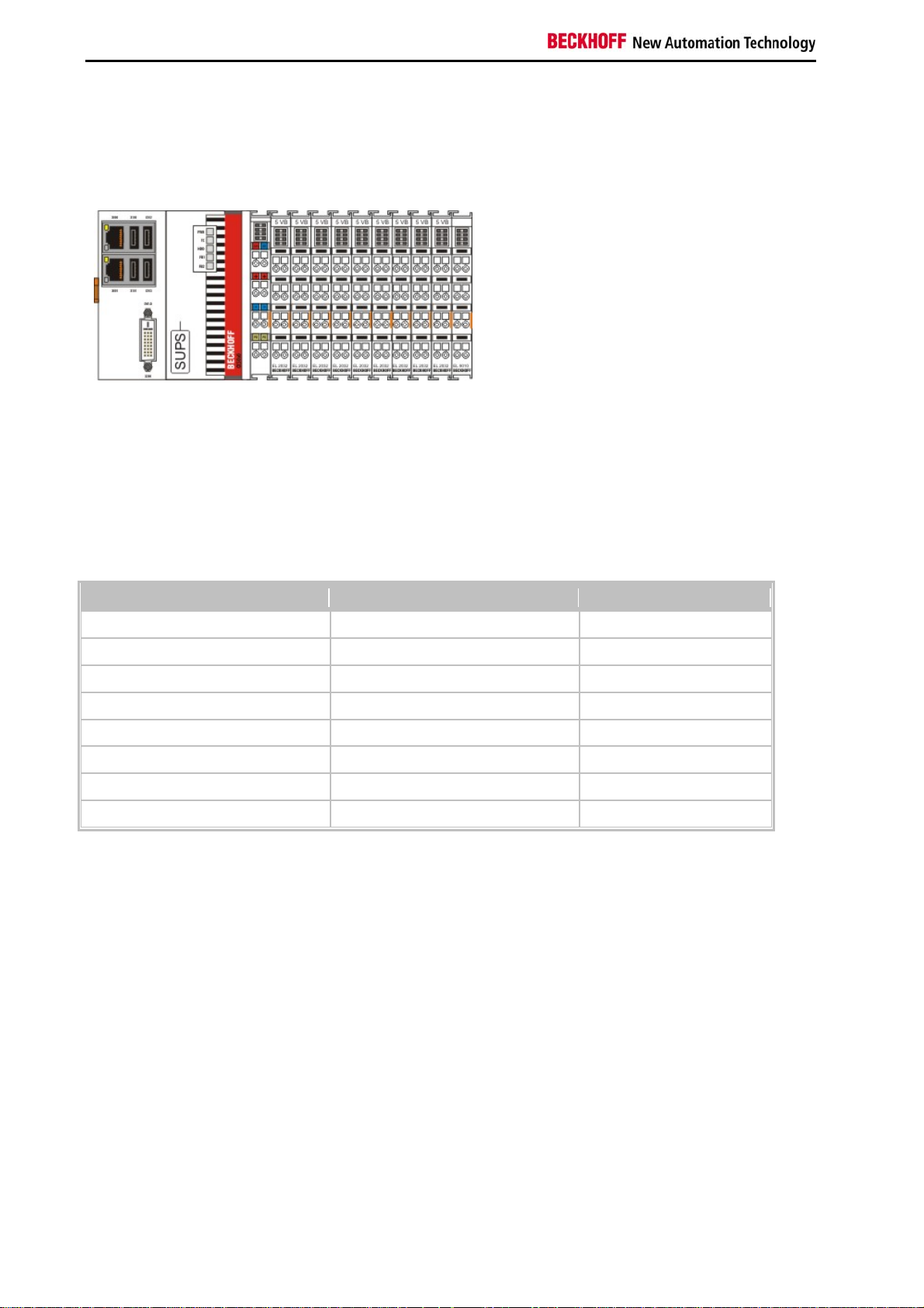
S-UPS: capacitive seconds UPS
The CX50x0 family features a built-in capacitive one-second UPS. It ensures a safe storage of the persistent
application data on the Compact Flash card.
Up to 1 MB of data can be saved. The UPS can be switched on and off via the BIOS:
Phoenix - AwardBIOS CMOS Setup Utility
PC Health Status
SUSV [Enabled] Item Help
SUSV holds USB [Enabled]
SUSV Status 100% Cap. / Charging
On Die Digital Temp.
Temp. Board
Temp DDR 57°C
CPU Core 1.07V
SCH Core 1.04V
...
SUSV
Option for deactivating the one-second UPS.
SUSV holds USB
47°C
56°C
If system buffering based on SUSV is active, this option can be used to switch the power supply for the USB port on
or off. This is important for data back-up on a USB storage medium, for example.
SUSV Status
This value indicates the status of the one-second UPS.
n% Cap. (n={0..100}) indicates the capacity of the UPS.
State (charging / discharging) describes the state of the one-second UPS.
Integration into a PLC
TwinCAT offers special function blocks for integrating the S-UPS into a PLC program. These are described below.
From TwinCAT 2.11R2 Build 2016 the required library is integrated in the installation. For older versions the library
TcSUPS.lib has to be copied into the TwinCAT library directory.
16 CX50x0 - Hardware Documentation
Page 19

Notes on the documentation
Overview
This library contains functions and function blocks which are needed in order to use the Seconds UPS. See sample
project Sample_S_UPS.pro.
Function Blocks
Name Description
FB_S_UPS Function block to use the Seconds UPS from the PLC.
FB_NT_QuickShutdown Internal function block for the QuickShutdown, used by the FB_S_UPS.
Functions
Name Description
F_GetVersionTcSUPS The function returns library version info.
Requirements
Component Version
TwinCAT on the development PC, on the target system 2.11 Build 1542 or higher
CX50x0 - Hardware Documentation 17
Page 20
Notes on the documentation
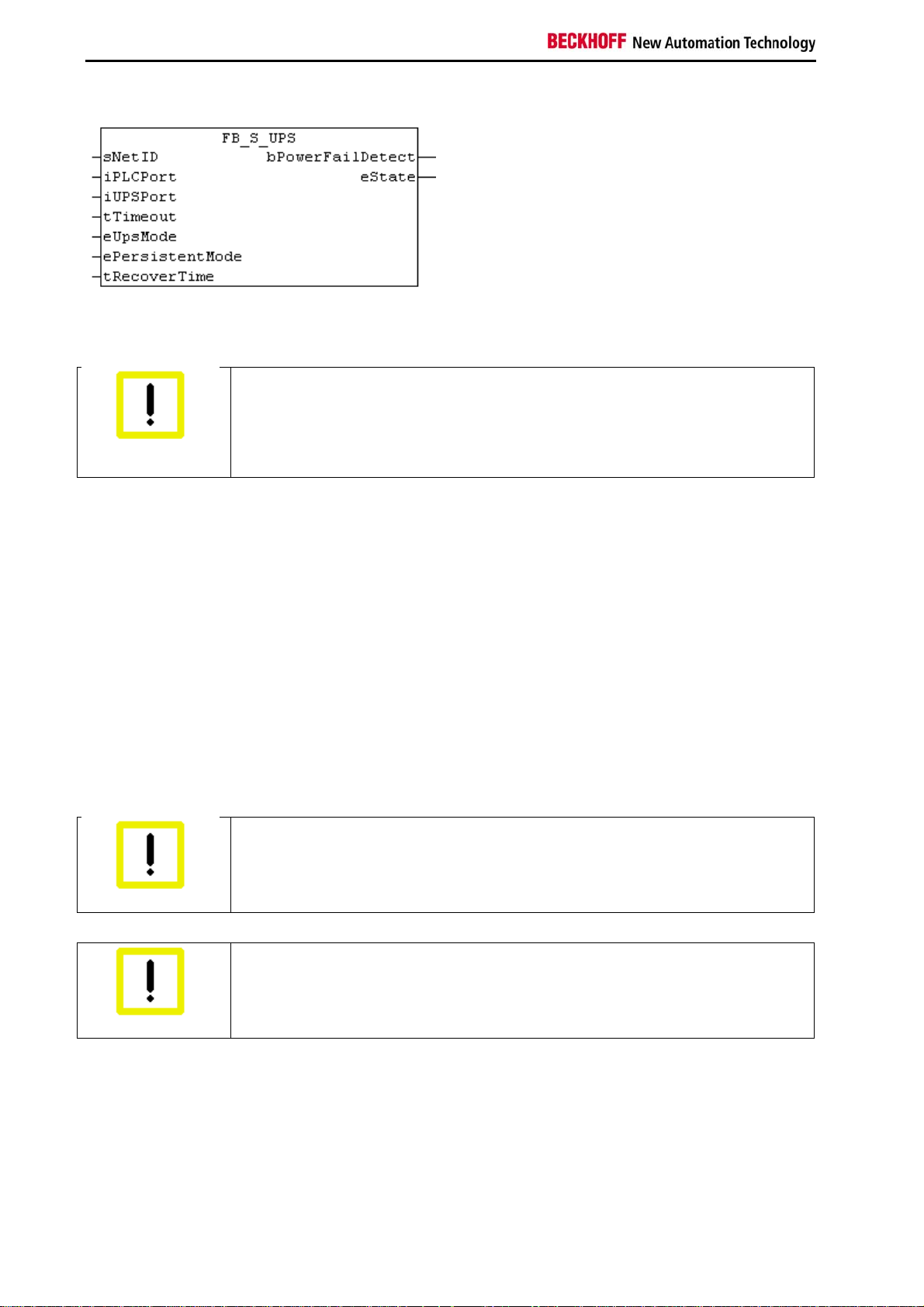
FUNCTION_BLOCK FB_S_UPS
The function block FB_S_Ups can be used on PCs with Seconds UPS, to communicate from the PLC with the UPS.
The FB_S_Ups can be used to save persistent data and to QuickShutdown the PC in case of a power failure. The
INPUTs of the FB_S_UPS should be used with the default values.
Data loss
The Seconds UPS is only capable of holding the voltage for a few seconds. This is just
enough time to save the persistent data. The used persistent saving mode must be
Attention
"SPDM_2PASS", even though if this could causes realtime problems. The router memory
must be big enough in order to save the persistent data!
Mode eSUPS_WrPersistData_Shutdown (default setting): The persistenten data are written and a QuickShutdown is
automatically performed.
Mode eSUPS_WrPersistData_NoShutdown: Only the persistenten data are written, a QuickShutdown will not be
performed.
Mode eSUPS_ImmediateShutdown: a QuickShutdown is immediatelly performed.
Mode eSUPS_CheckPowerStatus: only the powerfailure will be detected, no action is performed. In case of the
powerfailure the FB waits until the tRecoverTime (10s) has expired before it goes back to the PowerOK state.
The UPS will switch off the main board after the capacitors have been discharged, independent of the mode and
therefore independent of the writing of the persistent data and of the QuickShutdown, even if the power supply is
restored.
The capacity of the UPS is to small to hold the system alive during longer power outages. The saving of the
persistent data has to be done to the Compact Flash, since a hard disk cannot be operated if the UPS supplies the
voltage. After the saving of the persistent data a QuickShutdown will be executed.
Attention if files are modified:
If other applications or the PLC are keeping files open or write to files during a power
failure, then these files can get corrupted, since the QuickShutdown immediately reboots
Attention
the PC.
Attention if using Windows XP embedded:
The EWF (Enhanced Write Filter) or the FBWF (File Based Write Filter) has to be activated
in order to ensure the validity of the Windows XP embedded files on systems with a
Attention
In case of the EWF the TwinCAT\Boot folder needs to be located on a not protected partition (see in the registry:
HKEY_LOCAL_MACHINE\SOFTWARE\Beckhoff\TwinCAT\System\BootPrjPath).
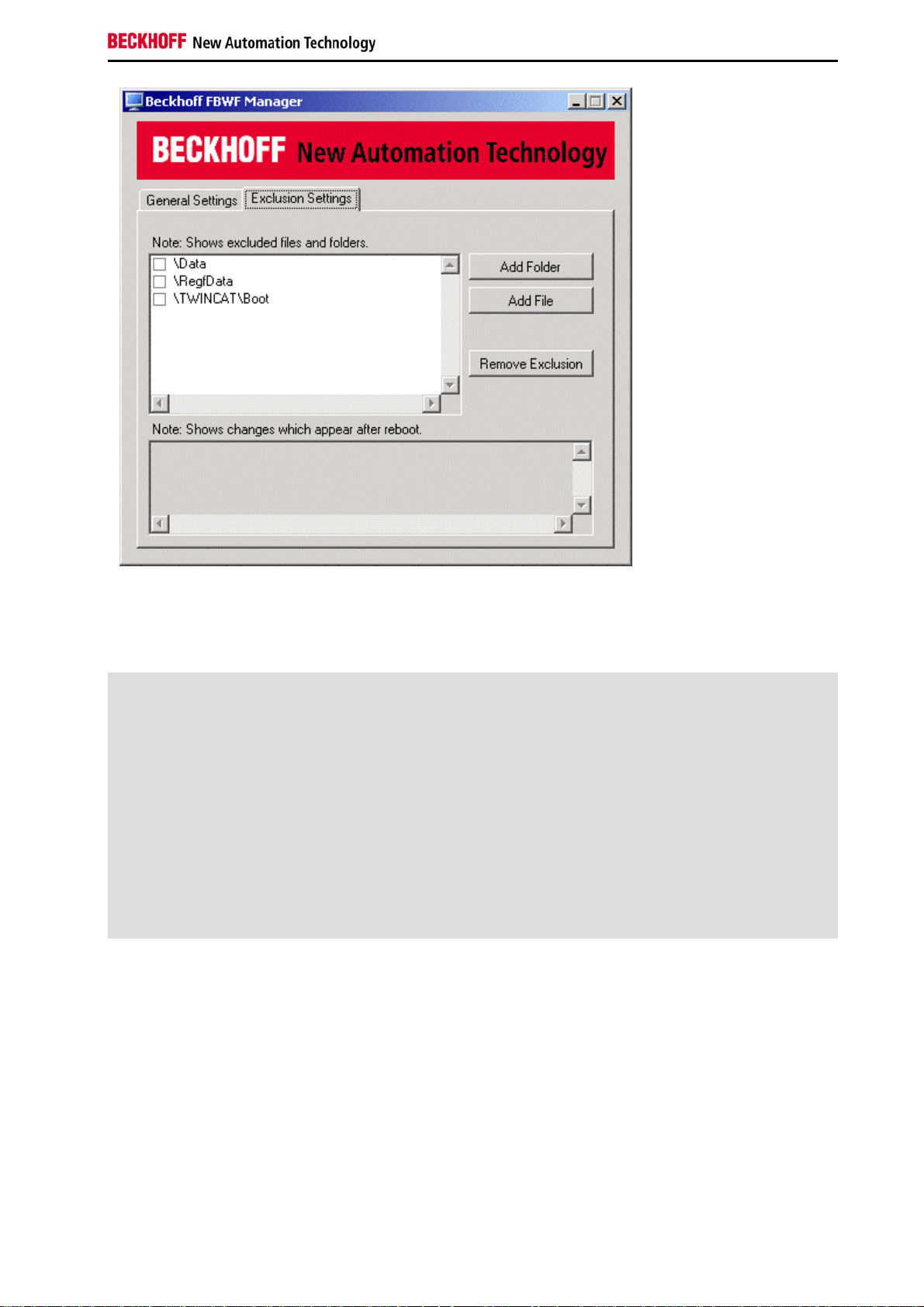
In case of the FBWF the TwinCAT\Boot folder needs to be excluded from the protection (see Beckhoff FBWF
Manager, Exclusion Settings).
Seconds UPS.
18 CX50x0 - Hardware Documentation
Page 21
Notes on the documentation
FUNCTION_BLOCK FB_S_UPS
VAR_INPUT
VAR_INPUT
sNetID : T_AmsNetId := ''; (* '' = local netid *)
iPLCPort : UINT := AMSPORT_R0_PLC_RTS1; (* PLC Runtime System for
writing persistent data *)
iUPSPort : UINT := 16#4A8; (* Port for reading Power
State of UPS, dafault 16#4A8 *)
tTimeout : TIME := DEFAULT_ADS_TIMEOUT; (* ADS Timeout *)
eUpsMode : E_S_UPS_Mode := eSUPS_WrPersistData_Shutdown; (* UPS mode
(w/wo writing persistent data, w/wo shutdown) *)
ePersistentMode : E_PersistentMode := SPDM_2PASS; (* mode for writing
persistent data *)
tRecoverTime : TIME := T#10s; (* ON time to recover from
short power failure in mode eSUPS_WrPersistData_NoShutdown/eSUPS_CheckPowerStatus *)
END_VAR
sNetID : AmsNetID of the PC.
iPLCPort : Port number of the PLC runtime system (AMSPORT_R0_PLC_RTS1 = 801,
AMSPORT_R0_PLC_RTS2 = 811, AMSPORT_R0_PLC_RTS3 = 821, AMSPORT_R0_PLC_RTS4 = 831).
iUPSPort : Port number for reading the UPS-State (default value is 16#4A8).
tTimeout : Timeout for the execution of the QuickShutdown.
eUpsMode : eUpsMode defines, if persistent data need to be written and if a QuickShutdown needs to be
executed.
The default value is eSUPS_WrPersistData_Shutdown, means with writing of the persistent
data and then a QuickShutdown. See E_S_UPS_Mode.
ePersistentMode : Mode for the writing of the persistent data. Default value is SPDM_2PASS.
tRecoverTime : Time which will be waited after a power failure (in case of UPS modes without shutdown) to
go back to the status PowerOK.
CX50x0 - Hardware Documentation 19
Page 22

Notes on the documentation
The tRecoverTime needs to be a little bit bigger than the maximum holding time of the UPS,
since the UPS will shut off even if the power supply is restored.
VAR_OUTPUT
VAR_OUTPUT
bPowerFailDetect : BOOL; (* TRUE while powerfailure is detected *)
eState : E_S_UPS_State; (* current ups state *)
END_VAR
bPowerFailDetect : TRUE if a power failure is detected; FALSE if the power supply is sufficiant.
eState : internal state of the function block, for the values see E_S_UPS_State.
VAR_GLOBAL
VAR_GLOBAL
eGlobalSUpsState : E_S_UPS_State; (* current ups state *)
END_VAR
eGlobalUpsState : internal state of the function block as a global copy of eState, for the values see
E_S_UPS_State.
20 CX50x0 - Hardware Documentation
Page 23

Notes on the documentation
FUNCTION_BLOCK FB_NT_QuickShutdown
The function block FB_NT_QuickShutdown is used to immediately reboot the PC without stopping TwinCAT or the
operating system Windows.
Attention:
The function block FB_NT_QuickShutdown is used internally from FB_S_UPS and is not intended to be used
elsewhere!
FUNCTION_BLOCK FB_NT_QuickShutdown
VAR_INPUT
VAR_INPUT
NETID :T_AmsNetId;
START :BOOL;
TMOUT :TIME := DEFAULT_ADS_TIMEOUT;
END_VAR
NETID : AmsNetID of the PC.
START : rising edge leads to an immediate reboot of the PC.
TMOUT : Timeout time.
VAR_OUTPUT
VAR_OUTPUT
BUSY :BOOL;
ERR :BOOL;
ERRID :UDINT;
END_VAR
BUSY : The QuickShutdown is being executed.
ERR : Is TRUE, if an error occurs.
ERRID : Delivers the error number in case that ERR is TRUE.
CX50x0 - Hardware Documentation 21
Page 24

Notes on the documentation
Functions
FUNCTION F_GetVersionTcSUPS
The function returns library version info.
FUNCTION F_GetVersionTcSUPS : UINT
VAR_INPUT
nVersionElement : INT;
END_VAR
nVersionElement : Version element:
1 : major number;
2 : minor number;
3 : revision number;
Development environment Target plattform PLC Libraries to include
TwinCAT v2.11.0 PC (i386) TcSUPS.Lib
22 CX50x0 - Hardware Documentation
Page 25

Notes on the documentation
Datatypes
E_S_UPS_Mode
eSUPS_WrPersistData_Shutdown:
Writing of persistent data and then a QuickShutdown
eSUPS_WrPersistData_NoShutdown:
only writing of the persistent data (no QuickShutdown)
eSUPS_ImmediateShutdown:
only QuickShutdown (no writing of persistent data)
eSUPS_CheckPowerStatus:
only check status (neither writing of persistent data nor a QuickShutdown)
CX50x0 - Hardware Documentation 23
Page 26

Notes on the documentation
E_S_UPS_State
eSUPS_PowerOK:
in all modes: Power supply is OK
eSUPS_PowerFailure:
in all modes: Power supply is faulty (only shown for one PLC cycle)
eSUPS_WritePersistentData:
in Mode eSUPS_WrPersistData_Shutdown: Writing of persistent data is active
in Mode eSUPS_WrPersistData_NoShutdown: Writing of persistent data is active
eSUPS_QuickShutdown:
in Mode eSUPS_WrPersistData_Shutdown: QuickShutdown is active
in Mode eSUPS_ImmediateShutdown: QuickShutdown is active
eSUPS_WaitForRecover:
in Mode eSUPS_WrPersistData_NoShutdown: wait for the reestablishment of the
power supply
in Mode eSUPS_CheckPowerStatus: wait for the reestablishment of the power
supply
eSUPS_WaitForPowerOFF:
in Mode eSUPS_WrPersistData_Shutdown: Wait for switching off of the PC by the
UPS
in Mode eSUPS_ImmediateShutdown: Wait for switching off of the PC by the UPS
24 CX50x0 - Hardware Documentation
Page 27

Notes on the documentation
4. Assembly and connecting
Unpacking, installation and transport
The specified storage conditions must be adhered to (see "Technical data").
Dimensions and weight of the individual modules:
Dimensions (H x W x D): 100 x 102 x 92 mm
Weight: 575 g (basic module)
Unpacking
Proceed as follows to unpack the unit:
1. Remove packaging.
2. Do not discard the original packaging. Keep it for transporting the device in the future.
3. Check the delivery for completeness by comparing it with your order.
4. Please keep the associated paperwork. It contains important information for handling the unit.
5. Check the contents for visible shipping damage.
6. If you notice any shipping damage or inconsistencies between the contents and your order, you should notify Beckhoff Service.
Danger of damage to the unit!
During transport in cold conditions, or if the unit is subjected to extreme temperature
swings, condensation on and inside the unit must be avoided.
Attention
Prior to operation, the unit must be allowed to slowly adjust to room temperature. Should
condensation occur, a delay time of approximately 12 hours must be allowed before the
unit is switched on.
Installation
The devices are designed for installation in control cabinets.
Shipping and relocation
Despite the robust design of the unit, the components are sensitive to strong vibrations and impacts. During
transport, your computer should therefore be protected from excessive mechanical stress. Therefore, please use the
original packaging.
CX50x0 - Hardware Documentation 25
Page 28

Notes on the documentation
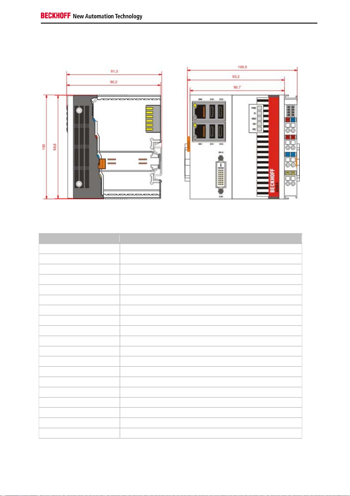
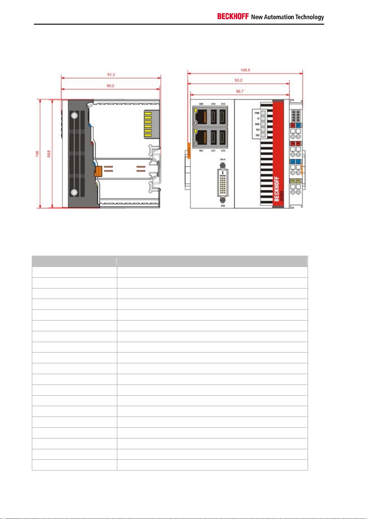
Dimensions
The following drawings show the dimensions of the CX50x0 devices.
Dimensions
26 CX50x0 - Hardware Documentation
Page 29

Notes on the documentation
Rear view
CX50x0 - Hardware Documentation 27
Page 30

Notes on the documentation
Installation on the mounting rail
Snapping onto the mounting rail
The CX50x0 can simply be snapped onto the mounting rail. To this end position the block on the mounting rail and
push it slightly until it engages on the right-hand side. The is indicated by a distinct click. Use a screwdriver to push
up the lock on the left-hand side, thereby turning it and causing it to engage audibly.
Avoid damage!
Do not force the module or apply excessive pressure!
Attention
Installation position
Comply with the permitted installation position and minimum distances!
The maximum ambient temperature for CPU modules mounted on a top-hat rail is 60 °C.
The orientation in which the device is fitted must be selected in such a way that cooling air
Attention
The high performance and the compact design of the CX50x0 systems may result in increased heat generation. The
heat is dissipated via a passive ventilation system. This system requires the unit to be mounted correctly. Ventilation
openings are located at the top and bottom of the housing. The system therefore has to be installed horizontally. This
ensures optimum air flow.
can flow vertically through the ventilation holes. The images show the permitted and two
incorrect installation positions.
Mounting must provide a clearance of 30 mm both above and below a CX50x0 device
combination to ensure adequate ventilation of the base CPU module and the power supply
unit.
28 CX50x0 - Hardware Documentation
Page 31

Notes on the documentation
Incorrect installation positions
The CX50x0 system must not be operated vertically on the top-hat rail. A vertical position would lead to insufficient
CPU ventilation, since the ventilation openings are located on the top and bottom of the housing. Installation of the
system on its side would also lead to inadequate ventilation.
CX50x0 - Hardware Documentation 29
Page 32

Notes on the documentation
Power supply
This power supply unit is equipped with an I/O interface, which permits connection of the Beckhoff Bus Terminals.
The power is supplied via the upper spring-loaded terminals labeled “24V” and “0V”.
The supply voltage supplies the CX system ant the terminal Bus and Bus Terminal with a voltage of 24 V DC (15 %/+20 %). The dielectric strength of the power supply unit is 500 V
transfers data, a separate power supply is required for the Bus Terminals. This is provided by means of the power
contacts, which are not connected to the power supply.
. Since the Terminal Bus (K- and E-bus) only
rms
Requirements for the 24V power supply
The power supply must be capable to supply 4A to guarantee proper function of CPU module and terminals.
LED
If the power supply unit is connected correctly and the power supply is switched on, the two upper LEDs in the
terminal prism are green. The left LED (Us) indicates the CPU supply. The right LED (Up) indicates the terminal
supply. The other LEDs indicate the Terminal Bus status. A detailed description of the LEDs can be found in section
"LED troubleshooting".
30 CX50x0 - Hardware Documentation
Page 33

Notes on the documentation
UL requirements
Danger
For the compliance of the UL requirements the CX-Controllers should only be supplied
by a 24 V
means of a fuse (in accordance with UL248), rated maximum 4 Amp.
by a 24 V
A NEC class 2 power supply shall not be connected in series or parallel with
another (class 2) power source!
This UL requirements are valid for all supply voltages of the CX-Controllers!
To meet the UL requirements, the CX-Controllers must not be connected to unlimited
power sources!
supply voltage, supplied by an isolating source and protected by
DC
power source, that has to satisfy NEC class 2.
DC
PE power contacts
Power contact "PE"
The ”PE" power contact must not be used for other potentials.
Attention
CX50x0 - Hardware Documentation 31
Page 34

Notes on the documentation
DVI-D connection
DVI-D connection (X200)
The DVI-D interface transfers digital data and is suitable for connecting a digital display. The resolution at the display
or the Beckhoff Control Panel depends on the distance from the display device. The maximum distance is 5 m.
DVI-D interface
The DVI interface does not use VGA signals, so that the connection of CRT VGA monitors
to the CX1000 system using a DVI to VGA adapter is not possible.
Note
DVI-D socket
Pin Assignment Pin Assignment Pin Assignment
1 TMDS Data 2- 9 TMDS Data 1- 17 TMDS Data 0-
2 TMDS Data 2+ 10 TMDS Data 1+ 18 TMDS Data 0+
3 TMDS Data 2/4 Shield 11 TMDS Data 1/3 Shield 19 TMDS Data 0/5 Shield
4 not connected 12 not connected 20 not connected
5 not connected 13 not connected 21 not connected
6 DDC Clock 14 + 5V Power 22 TMDS Clock Shield
7 DDC Data 15 Ground ( +5V, Analog H/V Sync) 23 TMDS Clock +
8 Analog Vertical Sync 16 Hot Plug Detect 24 TMDA Clock -
Resolution at the monitor
Resolution in pixels Distance of the interface from the moni to r
1920 x 1200 5 m
1600 x 1200 5 m
1280 x 1024 5 m
1024 x 768 5 m
800 x 600 5 m
640 x 480 5 m
32 CX50x0 - Hardware Documentation
Page 35

Notes on the documentation
USB connections
USB interface (X100 / X101 / X102 / X103):
The CX50x0 has 4 independent USB interfaces, for connecting keyboards, mice, touch screens and other input or
data storage devices. Keep an eye on the power consumption of the individual devices. Each port is limited to
500 mA.
The USB socket is a type A socket. The USB interface complies with the USB 2.0 specification.
Pin Assignment Typical assignment
1 VBUS Red
2 D- White
3 D+ Green
4 GND Black
Shell Shield Drain Wire
CX50x0 - Hardware Documentation 33
Page 36

Notes on the documentation
LAN connections
LAN interface (X000/ X001)
The CX50x0 systems have two independent LAN interfaces. Both ports are able to operate at speeds of 10 / 100 /
1000 Mbit. The LEDs on the left-hand sides of the RJ45 sockets indicate the status of the LAN connection. The upper
LED indicates whether the port is connected to a network. If this is the case the LED is yellow. The LED flashes if
data traffic takes place on the port. The lower LED indicates the connection speed. The LED is green if the speed is
10 or 100 Mbit. In 1000 Mbit mode (Gigabit) the LED is red.
Configuration of the RJ45 interface, port 1 (X000) / port 2 (X001)
PIN Signal Description
1 TD + Transmit +
2 TD - Transmit -
3 RD + Receive +
4 connected not used
5
6 RD - Receive -
7 connected not used
8
Independence of the ports
Both ports are independent of each other. In contrast to the CX1020 and CX9000 systems,
no switch is integrated. For a line topology an additional switch is required. The
Note
independent ports can be configured in different ways:
The upper port (1) is configured as Gigabit IT port,
The lower port (2) is configured for EtherCAT communication
in the delivery state.
34 CX50x0 - Hardware Documentation
Page 37

Notes on the documentation
RS232 connections (CX50x0-N030)
The CX50x0-N030 system interface provides an RS232 interface, COM1 (X300). It is implemented on a 9-pole SubD pin strip. If more than one interface is required the system can be extended via the Terminal Bus (K- or E-bus) or
Bus Terminals (KL/EL6001) which provide serial interfaces. The pin assignment is shown at the bottom of the page.
The maximum baud rate on both channels is 115 kbit. The interface parameters are set via the operating system or
from the PLC program.
RS232 COM interface (connector)
Pin assignment of the COM interface
PIN Signal Type Description
1 DCD Signal in Data Carrier Detected
2 RxD Signal in Receive Data
3 TxD Signal out Transmit Data
4 DTR Signal out Data Terminal Ready
5 GND Ground Ground
6 DSR Signal in Dataset Ready
7 RTS Signal out Request to Send
8 CTS Signal in Clear to Send
9 RI Signal in Ring Indicator
CX50x0 - Hardware Documentation 35
Page 38

Notes on the documentation
RS422/RS485 connections (CX50x0-N031)
The CX50x0-N030 system interface provides an RS422 or RS 485 interface, COM1 (X300). It is implemented on a 9pole Sub-D socket strip. If more than one interface is required the system can be extended via the Terminal Bus (Kor E-bus) or Bus Terminals (KL/EL6021) which provide serial interfaces. The pin assignment is shown at the bottom
of the page.
The maximum baud rate on both channels is 115 kbit. The interface parameters are set via the operating system or
from the PLC program.
COM interface (socket)
Pin assignment of the COM interface
PIN Signal Typ Beschreibung
2 TxD+ Data-Out + Transmit 422
3 TxD+ Data-In + Receive 422
5 GND Ground Ground
6 VCC VCC +5V
7 TxD- Data-Out - Transmit 422
8 TxD+ Data-In - Receive 422
For RS 485 pins 2 and 3 (data +) must be connected, and pins 7 and 8 (data -).
Setting of interface parameter
RS485, without echo, end-point (termination) default setting
Function Status
Echo on Off
Echo off On
Auto send on On
Always send on Off
Auto receive on On
Alway receive on Off
Term on On
Term on On
Note Change the parameter
If there is a need for other settings please contact our service department.
36 CX50x0 - Hardware Documentation
Page 39

Notes on the documentation
5. Operating/Configuration
EtherCAT cable redundancy
EtherCAT cable redundancy can be realised in the CX50x0 systems through the two independent Ethernet ports.
Minimum requirements:
1. EtherCAT redundancy supplement
2. EK1110 (bus extension)
3. EK1100 (Bus Coupler)
The supplement product on the Beckhoff website at
http://download.beckhoff.com/download/Software/TwinCAT/Supplement/TwinCAT_EtherCAT_Redundancy/Install/Tc
EcRedundancy.exe
can be downloaded. The required licence key can be ordered from our sales division. The required couplers are
ordered together with the other hardware. These components can then be used to configure the controller. The upper
figure shows a minimum configuration example for cable redundancy. Once the hardware has been wired and
commissioned, the supplement must be installed on the device, for example via a USB stick or the IT network. During
the installation the system asks for the licence key. The cable redundancy can be set up in the System Manager. The
first step involves reading the terminal configuration. Then select "Advanced Settings" under the "EtherCAT" tab in
the EtherCAT device properties. The second adapter can be set under the "Redundancy" menu. Use the "Search"
button to open the selection menu. Select "Local Area Connection 2 (Intel(R).....)" for the lower network connection
(X001). Click "OK" to complete the configuration.
CX50x0 - Hardware Documentation 37
Page 40

Notes on the documentation
The supplement only supports CABLE REDUNDANCY
This supplement only supports cable redundancy, which means that only the cable sections
can be regarded as fail-safe, i.e. connections between the couplers.
Note
Failures of individual terminals are not covered.
Further details can be found in the Beckhoff Information System under EtherCAT cable
redundancy.
Cases of failure
The two possible failures are described in the example below.
38 CX50x0 - Hardware Documentation
Page 41

Notes on the documentation
In this example the supply line for coupler EK1100 is faulty. The EK1100 terminals continue to run despite the cable
failure. The System Manager indicates the failure as follows:
The interruption is indicated by "LNK_MIS B" and "LNK_MIS A".
The next example shows a failure of the "return line":
CX50x0 - Hardware Documentation 39
Page 42

Notes on the documentation
In this case the second cable is faulty. The terminals at the coupler continue to run without malfunction. The System
Manager indicates the behavior as follows:
The interruption is indicated by "LNK_MIS C" at coupler EK1100.
The EtherCAT ring is expandable. The number of devices in the ring is controlled by licenses: up to 250, up to 1000,
more than 1000. A master is only able to bridge one failure. In the event of two failures the ring components will
continue to run up to the breaking points.
40 CX50x0 - Hardware Documentation
Page 43

Notes on the documentation
Switching on and off
Switching on
The power supply for the basic CPU module comes from the power supply unit. The basic CPU module starts
automatically when the power supply unit is connected to the mains.
Switching on for the first time
When you switch on the PC for the first time, the pre-installed operating system (optional) will be started.
Switching off
The Embedded PC switches off when the power supply unit is switched off. The control software typically running on
Embedded PCs should be shut down or stopped correctly. A user who may not close software may also not switch
the Embedded PC off, since data can be lost from the hard disk by switching off while software is running.
Once the software has been stopped, the operating system can be shut down. Only then should the power supply be
interrupted.
CX50x0 - Hardware Documentation 41
Page 44

Notes on the documentation
Note on using the setup
Changes in the BIOS settings may only be implemented by appropriately trained
staff.
The CX50x0 systems are delivered by Beckhoff Automation GmbH in a preconfigured state
and are therefore operational!
Attention
Within the individual setup pages, F6 can be used for loading fail-safe defaults, and F7 for optimised default values
for the individual setup entries. These default values are applied irrespective of whether the board was previously
booted successfully with a particular setup setting. The situation is different if the defaults are called from the TOP
menu. Once a setup setting that subsequently led to successful booting was saved, both menu items will load these
values as default for the setup pages. See also "Load Fail-Safe Defaults" and "Load Optimized Defaults".
The BIOS settings should only be executed by appropriately trained staff.
Under Windows CE the BIOS should not be changed at all, since the operating system is
adapted to the hardware configuration. Any change in the addresses or interrupts would
lead to unstable system behavior or even crashing.
Top menu
Phoenix - AwardBIOS CMOS Setup Utility
► Standard CMOS Features ► Frequency/Voltage Control
► Advanced BIOS Features Load Fail-Save Defaults
► Advanced Chipset Features Load Optimized Defaults
► Integrated Peripherals Set Password
► Power Management Setup Save & Exit Setup
► PnP/PCI Configuration Exit Without Saving
► PC Health Status
ESC: Quit ↑ ↓ →
← Select Item
F10: Save & Exit Setup
"Brief description of the function selected above"
A „►“ sign in front of the menu item indicates that a submenu is available. An "x" before a menu item indicates that
there is a setting option that has to be activated via a setting at a higher level.
Load Fail-Save Defaults
This option is used for absolute security settings. It is not suitable for continuous operation, but can be useful if the
PC malfunctions.
Load Optimized Defaults
This option is used for setting optimum values as recommended by the manufacturer.
Set Password
Here you can enter a setup password for preventing unauthorised invoking of the BIOS.
Save & Exit Setup
This option is used to save the settings and exit setup. Input: Y (Please note: enter Z with German keyboard).
Exit Without Saving
Quit setup without saving the settings. Setting: Y (Please note: enter Z with German keyboard).
42 CX50x0 - Hardware Documentation
Page 45

Notes on the documentation
Standard CMOS Features
This menu is used for setting date, time, hard disks, graphic mode and start-up behaviour. At the same time,
information about the memory configuration determined by the system is provided. The memory configuration
information cannot be changed. The setting options for date, time, graphics mode and startup behaviour are
described below. A new menu opens for setting the hard disk data.
Phoenix - AwardBIOS CMOS Setup Utility
Standard CMOS Features
Date (mm:dd:yy) Wed, Jun 30 2010 Item Help
Time (hh:mm:ss) 11 : 11 : 00
υ8; IDE Channel 0 Master [ None]
υ8; IDE Channel 0 Slave [ None]
Halt On [All, But Keyboard]
Base Memory 639K
Extended Memory 514,048K
Total Memory 515,072K
↑ ↓ → ← :Move Enter:Select +/-/PU/PD:Value F10:Save ESC:Exit F1:Help
F5: Previous Values F6: Fail-Safe Defaults F7: Optimized Defaults
Date (mm:dd:yy)
Options:
mm … month
dd … day
yy … year
Time (hh:mm:ss)
hh … hours
mm … minutes
ss … seconds
Halt On
This parameter can be used for stopping the boot process in the event of errors. Errors may be ignored. This menu
item is used to configure the settings.
All Errors (stop for all types of error)
No Errors (ignore all errors and continue system start-up)
All , But Keyboard (missing keyboard is ignored)
Base Memory
This option is used for displaying the conventional memory (0 KB to 640 KB) in order to indicate whether it was
detected by the POST.
Extended Memory
Available memory from the first MB to the maximum memory capacity.
Total Memory
This is the total of base memory, extended memory and other memory.
CX50x0 - Hardware Documentation 43
Page 46

Notes on the documentation
IDE Primary Master
This menu is used to set the data for the hard disk connected as master to the first IDE bus. The hard disk data (size,
number of cylinders, heads, sectors, pre-compensation and home position of the heads when the disk is switched off)
are displayed automatically for the connected hard disk.
Phoenix - AwardBIOS CMOS Setup Utility
IDE Primary Master
IDE HDD Auto-Detection [Press Enter] Item Help
IDE Channel 0 Master [Auto]
Access Mode [Auto]
Capacity 0 MB
Cylinder
Head 0
Precomp 0
Landing Zone 0
Sector 0
↑ ↓ → ← :Move Enter:Select +/-/PU/PD:Value F10:Save ESC:Exit F1:Help
F5: Previous Values F6: Fail-Safe Defaults F7: Optimized Defaults
IDE HDD Auto-Detection
Automatic detection of the hard disk is initiated by pressing the <Enter> key. After a few seconds the physical data of
the connected hard disk should be displayed in the lower section of the menu.
IDE Channel 0 Master
This parameter is used for configuring the IDE bus. The following options are available:
None (no hard disk connected to this bus connection)
Auto (auto-detection during each boot process)
Manual (the hard disk is addressed with the set parameters)
Access Mode
This option can be used to select the operating system for the hard disk. Setting options: CHS, LBA, LARGE, or Auto.
Auto is the recommended setting. Normal (standard) mode supports hard disks with a capacity of up to 528 MB. This
mode uses positions for data access that are specified via cylinders (CYLS), heads, and sectors. The older LBA
(Logical Block Addressing) mode can support hard disks with a capacity of up to 8.4 GB. This mode uses a different
method for calculating the position disk data to be accessed. It translates cylinders, heads and sectors into a logical
address for the data location. Large hard disks support this mode. The BIOS supports the INT 13h extension function
that enables the LBA mode to manage hard disk drives with a capacity of more than 8.4 GB. If the number of
cylinders (CYLs) on the hard disk exceeds 1024 and DOS cannot support it, or if your operating system does not
support LBA mode, LARGE mode should be selected. The following options are available for setting the hard disk
access mode:
CHS
LBA
44 CX50x0 - Hardware Documentation
Page 47

Notes on the documentation
LARGE
Auto
The following parameters are automatically determined and displayed.
Capacity
Storage capacity of the hard disk. This value is calculated from the individual hard disk parameters.
Cylinder
Define or set the number of cylinders. Depending on the BIOS version and the manufacturer it varies between 1,024
and 16,384 cylinders.
Head
Define or set the number of heads. The number is between 1 and 16 heads.
Precomp
Write pre-compensation, required for older hard disks. This parameter specifies the cylinder from which a difference
in the information density is to be expected.
Landing Zone
This parameter defines the so-called landing zone or park cylinder. This is the resting position for the hard disk head
when the hard disk motor is switched off.
Sector
Define or set the number of sectors per track. Up to 63 sectors are supported, for Phoenix up to 64.
CX50x0 - Hardware Documentation 45
Page 48

Notes on the documentation
IDE Primary Slave
This menu is used to set the data for the hard disk connected as master to the first IDE bus. The hard disk data (size,
number of cylinders, heads, sectors, pre-compensation and home position of the heads when the disk is switched off)
are displayed automatically for the connected hard disk.
Phoenix - AwardBIOS CMOS Setup Utility
IDE Primary Slave
IDE HDD Auto-Detection [Press Enter] Item Help
IDE Channel 0 Slave [Auto]
Access Mode [Auto]
Capacity 0 MB
Cylinder
Head 0
Precomp 0
Landing Zone 0
Sector 0
↑ ↓ → ← :Move Enter:Select +/-/PU/PD:Value F10:Save ESC:Exit F1:Help
F5: Previous Values F6: Fail-Safe Defaults F7: Optimized Defaults
IDE HDD Auto-Detection:
Automatic detection of the hard disk is initiated by pressing the <Enter> key. After a few seconds the physical data of
the connected hard disk should be displayed in the lower section of the menu.
IDE Primary Master:
This parameter is used for configuring the IDE bus. The following options are available:
None (no hard disk connected to this bus connection)
Auto (auto-detection during each boot process)
Manual (the hard disk is addressed with the set parameters)
Access Mode:
This option can be used to select the operating system for the hard disk. Setting options: CHS, LBA, LARGE, or Auto.
Auto is the recommended setting. Normal (standard) mode supports hard disks with a capacity of up to 528 MB. This
mode uses positions for data access that are specified via cylinders (CYLS), heads, and sectors. The older LBA
(Logical Block Addressing) mode can support hard disks with a capacity of up to 8.4 GB. This mode uses a different
method for calculating the position disk data to be accessed. It translates cylinders, heads and sectors into a logical
address for the data location. Large hard disks support this mode. The BIOS supports the INT 13h extension function
that enables the LBA mode to manage hard disk drives with a capacity of more than 8.4 GB. If the number of
cylinders (CYLs) on the hard disk exceeds 1024 and DOS cannot support it, or if your operating system does not
support LBA mode, LARGE mode should be selected. The following options are available for setting the hard disk
access mode:
CHS
LBA
LARGE
Auto
46 CX50x0 - Hardware Documentation
Page 49

Notes on the documentation
The following parameters are automatically determined and displayed.
Capacity
Storage capacity of the hard disk. This value is calculated from the individual hard disk parameters.
Cylinder
Define or set the number of cylinders. Depending on the BIOS version and the manufacturer it varies between 1,024
and 16,384 cylinders.
Head
Define or set the number of heads. The number is between 1 and 16 heads.
Precomp
Write pre-compensation, required for older hard disks. This parameter specifies the cylinder from which a difference
in the information density is to be expected.
Landing Zone
This parameter defines the so-called landing zone or park cylinder. This is the resting position for the hard disk head
when the hard disk motor is switched off.
Sector
Define or set the number of sectors per track. Up to 63 sectors are supported, for Phoenix up to 64.
CX50x0 - Hardware Documentation 47
Page 50

Notes on the documentation
Advanced BIOS Features
This menu is used to set the data for the hard disk connected as master to the first IDE bus. The hard disk data (size,
number of cylinders, heads, sectors, pre-compensation and home position of the heads when the disk is switched off)
are displayed automatically for the connected hard disk.
Phoenix - AwardBIOS CMOS Setup Utility
Advanced BIOS Features
υ8; CPU Feature [Press Enter] Item Help
υ8; Hard Disk Boot Priority [Press Enter]
CPU L1 & L2 Cache [Enabled]
Hyper Threading Technology Enabled
Quick Power On Self Test [Enabled]
First Boot Device [Harddisk]
Second Boot Device [LS120]
Second Boot Device [LS120]
Boot Other Device [Enabled]
Boot Up NumLock Status [On]
Gate A20 Option [Fast]
Typematic Rate Setting [Disabled]
Typematic Rate (Chars/Sec) 6
Typmatic Delay (Msec) 250
Security Option [Setup]
APIC Mode Enabled
MPS Version Control For OS [1.4]
OS Select For DRAM > 64 MB [Non-OS2]
HDD S.M.A.R.T. Capability [Enabled]
Full Screen Logo [Disabled]
↑ ↓ → ← :Move Enter:Select +/-/PU/PD:Value F10:Save ESC:Exit F1:Help
F5: Previous Values F6: Fail-Safe Defaults F7: Optimized Defaults
CPU Feature
This menu item can be used for setting the CPU behaviour for thermal profiles.
Virus Warning
On start-up the boot sectors are checked for changes since the last start. Setting options: Enabled (a virus warning
may appear until it is acknowledged with Confirm or switched off (Disabled)), Confirm (a required boot sector
modification, e.g. after reinstallation of an operating system, is confirmed), Disabled (boot sectors are not verified).
CPU L1 & L2 Cache
The cache memory is an additional memory that is substantially faster than the conventional DRAM (system
memory). If the CPU requests data, the system transfers theses data from the main DRAM to the cache memory for
faster access by the CPU. Setting options: Enable (standard) - cache activated, Disabled - cache deactivated.
Quick Power On Self Test
If this option is enabled the computer will start significantly faster. Booting will be up to 50 seconds faster with 64 MB
RAM or more. However, not all POST tests are carried out.
First Boot Device
Here you can specify which drive should boot first. First set the drive to be used as boot drive. Options:
LS120 (LS-Drive)
48 CX50x0 - Hardware Documentation
Page 51

Notes on the documentation
Hard Disk
CDROM (CD drive)
ZIP100 (Zip-Drive)
USB-FDD (USB-Floppy)
USB-ZIP (USB Zip-Drive)
USB-CDROM (USB CDROM)
Legacy LAN (network)
WIN CE
Disabled (deactivated)
Second Boot Device
This setting is used for booting, if the first boot device is not available. First set the drive to be used as boot drive.
Options:
S120 (LS-Drive)
Hard Disk
CDROM (CD drive)
ZIP100 (Zip-Drive)
USB-FDD (USB-Floppy)
USB-ZIP (USB Zip-Drive)
USB-CDROM (USB CDROM)
Legacy LAN (network)
WIN CE
Disabled (deactivated)
Second Boot Device
This setting is used for booting, if the first and second boot device are not available. First set the drive to be used as
boot drive. Options:
S120 (LS-Drive)
Hard Disk
CDROM (CD drive)
ZIP100 (Zip-Drive)
USB-FDD (USB-Floppy)
USB-ZIP (USB Zip-Drive)
USB-CDROM (USB CDROM)
Legacy LAN (network)
WIN CE
Disabled (deactivated)
Boot Other Device
This option offers two choices: Enabled or Disabled. The standard setting is Enabled. The Enabled setting enables
the BIOS to try all three types, i.e. "First Boot Device", "Second Boot Device" or "Third Boot Device".
Boot Up NumLock Status
State of the numeric keypad. With On it is activated, with Off not.
Gate A20 Option
Defines how the memory above 1MB is accessed. This should be set to Fast, in order to activate access through the
CX50x0 - Hardware Documentation 49
Page 52

Notes on the documentation
chipset. With the Normal setting it is accessed via the keyboard controller. This option may speed up older
computers. The first 64 K Block above 1 MB can be accessed in standard mode via address line A20. DOS will
anchor itself there, if DOS=High is inserted in Config.sys.
Typematic Rate Setting
This parameter is used to specify whether the options Keyboard Typematic Speed, Delay Before Keys Repeat,
Typematic Rate or Typematic Delay are available. If Disabled, the values are set to 6 characters per second, with a
keyboard delay of 250 ms. The settings can also be specified via the operating system.
Typematic Rate (Chars/Sec)
Specifies the repetition rate of the keyboard when a key is pressed. The options are 6, 8, 10, 12, 15, 20, 24 or 30
characters/second.
Typmatic Delay (Msec)
This value determines when the key function is activated after a key is pressed. The options are 250, 500, 750 or
1000 milliseconds.
Security Option
This parameter specifies the option for which a password applies. If the SYSTEM option is selected, a password has
to be entered during PC start-up. If the SETUP option is selected, a password is only required for accessing the
BIOS.
APIC Mode
This parameter switches the APIC Controller (Advanced Programmable Interrupt Controller) on or off. According to
the PC2001 regulations, the system may run in APIC mode. APIC mode offers extended IRQ resources (depending
on the board). Settings: Enabled or Disabled
MPS Version Control For OS
This option specifies what MPS version (Multi-Processor Specification) is used by this board. Setting options: 1.1 or
1.4 For older operating systems 1.1 should be used, otherwise leave as 1.4.
OS Select For DRAM > 64 MB
For OS/2 systems with more than 64 MB RAM, option OS/2 should be used.
HDD S.M.A.R.T. Capability
S.M.A.R.T. (Self Monitoring Analysis and Reporting Technology) is implemented in modern hard disks. Among other
things, in conjunction with suitable software this technology can be used to detect hard disk read or speed problems
at an early stage. If the option is activated, the system will issue a warning regarding an impending crash, for
example. The results can be analysed with Norton-Utilities from version 3.0, for example.
Full Screen Logo
This option can be used to specify that the start logo should fill the whole screen during booting, thereby hiding the
start data. Setting options: Enabled, Disabled
50 CX50x0 - Hardware Documentation
Page 53

Notes on the documentation
CPU Features
This menu is used for setting the CPU behaviour with thermal profiles.
Phoenix - AwardBIOS CMOS Setup Utility
CPU Feature
Thermal Management Disabled Item Help
Limit CPUID MaxVal [Disabled]
C1E Function [Disabled]
CPU C State Capability [Disabled]
Execute Disable Bit [Enabled]
Virtualization Technology [Enabled]
↑ ↓ → ← :Move Enter:Select +/-/PU/PD:Value F10:Save ESC:Exit F1:Help
F5: Previous Values F6: Fail-Safe Defaults F7: Optimized Defaults
Thermal Management
The processor used has a thermal monitor. In order to maintain real-time it is switched off.
Limit CPUID MaxVal
This option supports Prescott CPUs in older operating systems. Enabled: Activate this option if an older operating
system is used. Disabled: Deactivate the CPUID limit if Windows XP is used.
C1E Function
This option is only available for certain processors with C1E (Enhanced Halt State) function.
CPU C State Capability
This option can be used to set the lowest C-state of the CPU. Usually DISABLED should be selected.
DISABLED: function off
C2 (STOP Grant): CPU clock is stopped, API functions run with normal speed
C4 (Deeper Sleep): CPU voltage is reduced.
C6 (Deep Power Down): CPU voltage is reduced to 0 V.
Execute Disable Bit
This option represents a safety function that can help you to protect your CPU and your operating system from
malicious software that may execute a code and harm the BIOS. This option is available only if the CPU supports this
function. Setting options: Enabled, Disabled.
Virtualization Technology
This option activates or deactivates the additional hardware capabilities of virtualization technology. Intel
Virtualization Technology (code names Vanderpool or Vanderpool Technology) describes the implementation of a
Secure Virtual Machine by Intel. AMD Virtualization or AMD-V (also known under the code name "Pacifica") is a
technology for virtualization of a computer and refers to AMD's implementation of a Secure Virtual Machine in
conjunction with an IOMMU. Setting options: Enabled, Disabled.
CX50x0 - Hardware Documentation 51
Page 54

Notes on the documentation
Advanced Chipset Features
This menu is used for memory functions settings. Such settings should be implemented cautiously since they can
affect the stability of the whole system.
Phoenix - AwardBIOS CMOS Setup Utility
Advanced Chipset Features
DRAM Timing Selectable [by SPD] Item Help
System BIOS Cachable [Enabled]
Video BIOS Cachable [Disabled]
** On-Chip VGA Setting **
On-Chip Video Memory Size [128 MB]
On-Chip Frame Buffer Size [8 MB]
Current Configuration
Boot Type DVI
DVO
↑ ↓ → ← :Move Enter:Select +/-/PU/PD:Value F10:Save ESC:Exit F1:Help
F5: Previous Values F6: Fail-Safe Defaults F7: Optimized Defaults
DRAM Timing Selectable
This submenu can be used for setting the optimum timing for options, depending on the memory modules used. By
default the options are configured via 'By SPD', by reading the content of the SPD (Serial Presence Detect ) unit.
During this process critical parameter information relating to memory type, size, speed, voltage interface and module
banks are stored in the EEPROM.
System BIOS Cachable
If the function is active the cache memory makes use of the available BIOS-ROM, thereby enhancing the
performance, although this applies mainly to DOS and Win3.x. Under Windows 95/98 this option is less relevant.
Video BIOS Cachable
If this option is enabled, the cache memory can take the VIDEO BIOS of the graphics card at the address C0000h to
C7FFFh into account. Please note that caching involves risks, if the cache contains the code and a program wants to
write into the BIOS area. If this option is enabled, the option Video BIOS Shadow should also be activated. Under
DOS the speed benefits is around 40%. Under Win.x and DOS this option should be enabled, otherwise it should be
disabled.
On-Chip Video Memory Size
This option can be used to set the size of the video memory. (128 MB, 256 MB)
On-Chip Frame Buffer Size
This option can be used to adapt the frame buffer. Various setting options are available. The individual options can
be used to try and enhance the performance. Make sure the system stability is not affected and proceed step-by-step
(1 MB, 4 MB, 8 MB)
Current Configuration
The current graphics configuration is shown here. In this device it is set to DVO.
Boot Type
This setting indicates the output source for the boot process. Since the CX50x0 devices support graphic outputs only
via DVI-I, this setting is always set to DVI.
52 CX50x0 - Hardware Documentation
Page 55

Notes on the documentation
Integrated Peripherals
This option can be used for audio, multimedia and LAN interface settings.
Phoenix - AwardBIOS CMOS Setup Utility
Integrated Peripherals
υ8; OnChip IDE Device [Press Enter] Item Help
υ8; Onboard Device [Press Enter]
υ8; SuperIO Device [Press Enter]
υ8; USB Device Setting [Press Enter]
↑ ↓ → ← :Move Enter:Select +/-/PU/PD:Value F10:Save ESC:Exit F1:Help
F5: Previous Values F6: Fail-Safe Defaults F7: Optimized Defaults
OnChip IDE Device
Here you can set the onboard IDE controller settings.
Onboard Device
This menu can be used for audio, multimedia and LAN interface settings.
SuperIO Device
Here you can set the settings for the serial interfaces (port 1 and port 2).
USB Device Setting
This option can be used for USB interface settings.
CX50x0 - Hardware Documentation 53
Page 56

Notes on the documentation
Onchip IDE Device
This menu is used for setting the IDE interfaces.
Phoenix - AwardBIOS CMOS Setup Utility
Onchip IDE Device
IDE HDD Block Mode
IDE Primary Master PIO [Auto]
IDE Primary Master PIO [Auto]
IDE Primary Master UDMA [Auto]
IDE Primary Slave UDMA [Auto]
[Enabled] Item Help
↑ ↓ → ← :Move Enter:Select +/-/PU/PD:Value F10:Save ESC:Exit F1:Help
F5: Previous Values F6: Fail-Safe Defaults F7: Optimized Defaults
IDE HDD Block Mode
This option is used to activate block mode for IDE hard disks. If your drive supports this mode and this option is
activated, the system will read the number of blocks per request from the configuration sector of the hard disk. The
recommended setting is Enabled, although it should be noted that this is not suitable for older hard disks.
IDE Primary Master PIO
PIO refers to the concept of programmed input and output. Instead of the BIOS issuing an instruction sequence for
initiating a data transfer from or to the hard disk, PIO enables the BIOS to notify the controller what task should be
executed. The task is then fully handled by the controller and the CPU. Your system supports five PIO modes, 0
(standard) to 4, with the main difference relating to timing. If "Auto" (automatic) is selected, the BIOS will assess your
drive and automatically specify the optimum PIO mode. Auto: The BIOS automatically sets the system value
depending on the timing of your hard disk drive. Mode 0-4: You can select a mode suitable mode that matches the
timing your hard drive.
IDEPrimary Master UDMA
This option is used to configure the Ultra-DMA/33 mode of your hard disk. Setting options: Auto, Enabled, Disabled.
The option should be set to Enabled.
IDE Primary Slave UDMA
This option is used to configure the Ultra-DMA/33 mode of your hard disk. Setting options: Auto, Enabled, Disabled.
The option should be set to Enabled.
54 CX50x0 - Hardware Documentation
Page 57

Notes on the documentation
Onboard Device
This menu is used for configuring the audio, multimedia and LAN interfaces.
Phoenix - AwardBIOS CMOS Setup Utility
Onboard Device
Intel HD Audio Controller [Disabled] Item Help
USB Client Routing [Disabled]
SDIO/MMC Controller [Disabled]
Onboard Lan Controller Enabled
Console Redirect [Disabled]
x Serial Port Mode 115200,8,n,1
x After Boot Enabled
x Flow Control Signals Ignore
↑ ↓ → ← :Move Enter:Select +/-/PU/PD:Value F10:Save ESC:Exit F1:Help
F5: Previous Values F6: Fail-Safe Defaults F7: Optimized Defaults
Intel HD Audio Controller
Option for activating the internal audio controller. The function is disabled since currently no associated extension is
implemented.
USB Client Routing
Option for configuring the second USB port with USB client functionality.
SDIO/MMC Controller
Option for activating/deactivating the SDIO / MMC controller. In general the CX50x0 units are not equipped with the
required hardware. The function is therefore disabled.
Onboard Lan Controller
The two Gigabit LAN ports are always enabled.
Console Redirect
Option for redirecting the boot process output to the serial interface. If the function is enabled the communication
parameters in the locked menus can be set.
Serial Port Mode
Option for setting the baud rate, number of bits, parity and stop bit.
After Boot
The console can remain active after the boot process. This function is only supported by a small number of operating
systems.
Flow Control Signals
Option for activating or deactivating hardware flow control.
CX50x0 - Hardware Documentation 55
Page 58

Notes on the documentation
SuperIO Device
This menu is used for configuring the USB and audio interfaces.
Phoenix - AwardBIOS CMOS Setup Utility
SuperIO Device
Onboard Serial Port 1 [3F8/IRQ4] Item Help
Onboard Serial Port 2 [2F8/IRQ3]
UART Mode Select [Normal]
RxD, TxD Active Hi, Lo
IR Transmission Delay Enabled
UR2 Duplex Mode Half
Use IR Pins IR-Rx2Tx2
↑ ↓ → ← :Move Enter:Select +/-/PU/PD:Value F10:Save ESC:Exit F1:Help
F5: Previous Values F6: Fail-Safe Defaults F7: Optimized Defaults
Onboard Serial Port1
Configuration of the serial interface settings: IRQ4 (used for the first serial port), Disabled (no interrupt is used).
Setting options: Auto, 3F8/IRQ4, 2F8/IRQ4, 3E8/IRQ4 or 2E8/IRQ4 .
Onboard Serial Port 2
Configuration of the serial interface settings: IRQ3 (used for the second serial port), Disabled (no interrupt is used).
Setting options: Auto, 3F8/IRQ3, 2F8/IRQ3, 3E8/IRQ3 or 2E8/IRQ3.
UART Mode Select
Mode for the serial interface driver. Setting options:
Normal for RS-232 serial interface
ASKIR for amplitude keyed shift interface for IR devices
IrDA for IrDA interface
RxD, TxD Active
Settings cannot be changed in standard mode. This option is used for setting IR transmission/reception to High or
Low.
IR Transmission Delay
If this option is activated, transmission is delayed. Setting options: Enabled, Disabled.
UR2 Duplex Mode
This option is used for configuring infrared devices. Setting options: Full or Half. Please refer to the IR device manual
regarding the duplex mode setting.
Use IR Pins
This option is identical to the TxD, RxD Active option. The required information can be found in the documentation for
your IR device.
56 CX50x0 - Hardware Documentation
Page 59

Notes on the documentation
USB Device Settings
This menu is used for configuring the USB and audio interfaces.
Phoenix - AwardBIOS CMOS Setup Utility
Onboard Device
USB 1.0 Controller [Enabled] Item Help
USB 2.0 Controller [Enabled]
USB Operation Mode [High Speed]
USB Keyboard Function [Enabled]
USB Storage Function [Enabled]
*** USB Mass Storage Device Boor Settings ***
BeckhoffAutomation 2000 [Auto mode]
↑ ↓ → ← :Move Enter:Select +/-/PU/PD:Value F10:Save ESC:Exit F1:Help
F5: Previous Values F6: Fail-Safe Defaults F7: Optimized Defaults
USB 1.0 Controller
The board contains a USB 1.0 chipset with support for USB 1.0. The option can be switched on or off here.
USB 2.0 Controller
The board contains a USB 2.0 chipset with support for USB 2.0. The option can be switched on or off here.
USB Operation Mode
Option for setting the data transfer rate of the USB port:
High Speed: Each device is connected based on the device-specific speed.
Full / Low Speed: All devices are connected with 1.5 MB/s or 12 MB/s.
USB Keyboard Function
The USB keyboard driver (if available) of the BIOS can be activated/deactivated here. This enables the USB
keyboard to be operated during and after system startup, if your operating system does not have a USB driver.
USB Storage Function
Option for activating or deactivating USB mass storage support.
BeckhoffAutomation 2000
This function is intended only for internal purposes!
CX50x0 - Hardware Documentation 57
Page 60

Notes on the documentation
Power Management Setup
This menu is used for power management settings.
Phoenix - AwardBIOS CMOS Setup Utility
Power Management Setup
Power-Supply Type [AT] Item Help
APCI Function
ACPI Suspend Type [S1(POS)]
Soft-Off by PWR-BTTN [Instant-Off]
υ8; HPET Feature [Press Enter]
υ8; Intel DTS Feature [Press Enter]
Enabled
↑ ↓ → ← :Move Enter:Select +/-/PU/PD:Value F10:Save ESC:Exit F1:Help
F5: Previous Values F6: Fail-Safe Defaults F7: Optimized Defaults
Power-Supply Type
Option for setting the power supply unit mode. In AT mode the power supply unit remains switched on when the
system is shut down. In ATX mode the internal power supply unit of the controller switches off. For a restart the
power supply must be interrupted briefly.
APCI function
APCI is always active.
ACPI Suspend Type
The ACPI option (Advanced Configuration and Power Interface) is an extended PnP and power management
function.
S1(POS): Switches the PC to sleep mode. Only a few functions are switched off and are available
again at a keystroke
S3(STR): Option for writing the current state of the operating system to the RAM. In this case only the
RAM is supplied with power.
Soft-Off by PWR-BTTN
This function is not used, since no power button is installed.
58 CX50x0 - Hardware Documentation
Page 61

Notes on the documentation
HPET power management
This menu is used for HPET settings.
Phoenix - AwardBIOS CMOS Setup Utility
HPET Feature
HPET Support [Enable] Item Help
HPET Mode [32-bit mode]
↑ ↓ → ← :Move Enter:Select +/-/PU/PD:Value F10:Save ESC:Exit F1:Help
F5: Previous Values F6: Fail-Safe Defaults F7: Optimized Defaults
HPET Support
Activates or deactivates HPET support . It is a kind of timer within the PC that is able to trigger an interrupt with very
high precision, thereby enabling other programs to better synchronise various applications. If multimedia applications
are used this option should be enabled. Setting options: Enabled, Disabled.
HPET Mode
Two operating modes are available: 32-bit mode and 64-bit mode.
CX50x0 - Hardware Documentation 59
Page 62

Notes on the documentation
DTS Power management
Menu for setting the digital thermo sensors.
Phoenix - AwardBIOS CMOS Setup Utility
DTS Feature
Intel DTS function [Enable] Item Help
DTS Active temperature [55°C]
Passive Cooling Trip Point [95°C]
Passive TC1 Value [ 2]
Passive TC2 Value [ 2]
Passive TSP Value [ 2]
Critical Trip Point [POR]
↑ ↓ → ← :Move Enter:Select +/-/PU/PD:Value F10:Save ESC:Exit F1:Help
F5: Previous Values F6: Fail-Safe Defaults F7: Optimized Defaults
Intel DTS function
System monitoring is switched on or off by the thermal sensors. For operation in controller mode the DTS function is
switched off in order to avoid problems with real-time functionality.
DTS Active temperature
At this temperature the system switches on the fan.
Passive Cooling Trip Point
At this temperature the CPU is slowed down in order to cool it.
Passive TC1 Value
This value specifies the performance reduction for TC1.
The formula is:
Performance [%]= _TC1 * ( Tn - Tn-1 ) + _TC2 * (Tn. - Tt)
Passive TC2 Value
This value specifies the performance reduction for TC2.
The formula is:
Passive TSP Value
This option is used to specified how often the system should analyse the temperature sensors. Values are entered in
10th of a second.
Critical Trip Point
At this temperature the CPU is switched off in order to prevent damage.
Performance [%]= _TC1 * ( Tn - Tn-1 ) + _TC2 * (Tn. - Tt)
60 CX50x0 - Hardware Documentation
Page 63

Notes on the documentation
PnP/PCI Configurations
This menu is used for configuring the PCI bus and Plug and Play Management.
Phoenix - AwardBIOS CMOS Setup Utility
PnP/PCI Configurations
Init Display First [PCI Slot] Item Help
Reset Configuration Data [Enabled]
Resources Controlled By [Manual]
υ8; IRQ Resources [Press Enter]
PCI/VGA Palette Snoop [Disabled]
↑ ↓ → ← :Move Enter:Select +/-/PU/PD:Value F10:Save ESC:Exit F1:Help
F5: Previous Values F6: Fail-Safe Defaults F7: Optimized Defaults
Init Display First
This option can be used to specify which graphics card should be initialised first: either PCI slot, onboard or PCIEx.
Reset Configuration Data
If activated, the option ensures that the BIOS deletes the information relating to built-in components and their
resources and reconfigures them (all settings are reset). Setting options: Enabled, Disabled.
Resources Controlled By
Specifies whether the PnP settings should be assigned via setup or automatically. Auto should be used, if there are
no problems with IRQ or DMA assignments. The default is auto.
IRQ Resources
If these resources are set manually, each system interrupt should be assigned a type, depending on the type of
device using the interrupt.
PCI/VGA Palette Snoop
Used by multimedia video cards. This function should be switched on (Enabled), depending on the card. It is
switched off by default.
CX50x0 - Hardware Documentation 61
Page 64

Notes on the documentation
IRQ Resources
This menu is used for disabling interrupts for free allocation to PCI slots.
Phoenix - AwardBIOS CMOS Setup Utility
IRQ Resources
IRQ-3 assigned to [PCI Device] Item Help
IRQ-4 assigned to [PCI Device]
IRQ-5 assigned to [PCI Device]
IRQ-7 assigned to [PCI Device]
IRQ-9 assigned to [PCI Device]
IRQ-10 assigned to [PCI Device]
IRQ-11 assigned to [PCI Device]
IRQ-12 assigned to [PCI Device]
↑ ↓ → ← :Move Enter:Select +/-/PU/PD:Value F10:Save ESC:Exit F1:Help
F5: Previous Values F6: Fail-Safe Defaults F7: Optimized Defaults
IRQ-n assigned to ( n = {3,4,5,7,9,10,11,12,14,15} )
This parameter is used for disabling (reserving) an interrupt for free allocation. If the setting [PCI Device] is used, the
interrupt is allocated dynamically.
62 CX50x0 - Hardware Documentation
Page 65

Notes on the documentation
PC Health Status
This menu is used for displaying the settings for CPU and motherboard temperatures, power supply, and fan speed.
Phoenix - AwardBIOS CMOS Setup Utility
PC Health Status
SUSV [Enabled] Item Help
SUSV holds USB [Enabled]
SUSV Status 100% Cap. / Charging
On Die Digital Temp.
Temp. Board
Temp DDR 57°C
CPU Core 1.07V
SCH Core 1.04V
CPU VTT 1.04V
Memory 1.8 V 1.80V
+3.3 V 3.39V
+5 V 5.29V
+1.5 V 1.480V
VBatt 3.07V
Fan1 Speed 0 RPM
Board Revision 0
47°C
56°C
↑ ↓ → ← :Move Enter:Select +/-/PU/PD:Value F10:Save ESC:Exit F1:Help
F5: Previous Values F6: Fail-Safe Defaults F7: Optimized Defaults
SUSV
Option for deactivating the one-second UPS.
SUSV holds USB
If system buffering based on SUSV is active, this option can be used to switch the power supply for the USB port on
or off. This is important for data back-up on a USB storage medium, for example.
SUSV Status
This value indicates the status of the one-second UPS.
n% Cap. (n={0..100}) indicates the capacity of the UPS.
State (charging / discharging) describes the state of the one-second UPS.
On Die Digital Temp.
Temperature inside the CPU.
Temp. Board
Board temperature.
Temp. DDR
Memory temperature.
CPU Core
CPU core voltage.
SCH Core
CPU VTT voltage.
CX50x0 - Hardware Documentation 63
Page 66

Notes on the documentation
CPU VTT
CPU VTT voltage.
Memory 1.8 V
Memory power supply (1.8 V).
+3.3 V
Supply voltage, 3.3 V.
+5 V
Supply voltage, 5 V.
+1.5 V
Supply voltage, 1.5 V.
VBatt
Battery voltage.
Fan1 Speed
0 RPM, since no fan is connected.
Board Revision
Hardware version of the CPU board.
64 CX50x0 - Hardware Documentation
Page 67

Notes on the documentation
Frequency/Voltage Control
This menu can be used to implement the CLK setting for the PCI bus. Moreover, the tolerances for the power supply
can be specified.
Phoenix - AwardBIOS CMOS Setup Utility
Frequency/Voltage Control
XDP-Clock [Disabled] Item Help
↑ ↓ → ← :Move Enter:Select +/-/PU/PD:Value F10:Save ESC:Exit F1:Help
F5: Previous Values F6: Fail-Safe Defaults F7: Optimized Defaults
XDP-Clock
This setting is for internal purposes and may not be modified.
CX50x0 - Hardware Documentation 65
Page 68

Notes on the documentation
6. Error handling and diagnostics
CPU basic moule
LEDs on the basic CPU module
Display LED Meaning
PWR Power supply
The Power LED comes on when the device is connected to a live power supply unit
(green).
TC TwinCAT status LED
TwinCAT is in Run mode (green)
HDD Read/Write Compact Flash (red)
FB1 Status LED1 for fieldbus
TwinCAT is in Stop mode (red)
TwinCAT is in Config mode (blue)
Indicates access to the CF card.
(function is written at the fieldbus interface)
FB2 Status LED2 for fieldbus
(function is written at the fieldbus interface)
66 CX50x0 - Hardware Documentation
Page 69

Notes on the documentation
LEDs of the K-bus-power supply unit (CX50x0-1xxx)
After switching on, the power supply immediately checks the connected Bus Terminal configuration. Error-free startup is signaled by the red "I/O ERR” LED being extinguished. If the ”I/O ERR" LED blinks, an error in the area of the
terminals is indicated. The error code can be determined from the frequency and number of blinks. This permits rapid
rectification of the error.
Display LED Meaning
The I/O error LED blink code
fast blinking Start of the error code
first slow sequence
second slow sequence
Us 24 V Power supply for the CPU module
The LED lights green if the power supply is correct.
Up
24V
K-BUS
RUN
K-BUS
ERR
Power supply for terminal bus.
The LED lights green if the power supply is correct.
K-Bus diagnostics
The green LED lights up in order to indicate fault-free
operation. "Fault-free" means that the communication
with the fieldbus system is also running.
K-Bus diagnostics
The red LED flashes to indicate an error. The red LED
blinks with two different frequencies.
Error code
Error code argument
LEDs for K-Bus diagnosis
Error code
Error code
argument Description Remedy
Persistent,
continuous
flashing
1 pulse
2 pulses
3 pulses
4 pulses
EMC problems
Check power supply for overvoltage or
undervoltage peaks
Implement EMC measures
If a K-Bus error is present, it can be lo-
calised by a restart of the power supply
(by switching it off and then on again)
0 EEPROM checksum error Revert to the manufacturer’s setting
1 Code buffer overflow Insert fewer Bus Terminals. Too many entries in
the table for the programmed configuration
2 Unknown data type Software update required for the power supply
0 Programmed configuration
has an incorrect table entry
n (n > 0) Table comparison (Bus
Terminal n)
0 K-Bus command error
Check programmed configuration for
correctness
Incorrect table entry
No Bus Terminal inserted
One of the Bus Terminals is defective;
halve the number of Bus Terminals attached and check whether the error is
still present with the remaining Bus
Terminals. Repeat until the defective
Bus Terminal is located.
0 K-Bus data error, break
behind the power supply
Check whether the n+1 Bus Terminal is correctly
connected; replace if necessary.
n Break behind Bus Terminal n Check whether the Bus End Terminal 9010 is
connected.
CX50x0 - Hardware Documentation 67
Page 70

Notes on the documentation
5 pulses
7 pulses
9 pulses
14 pulses
15 pulses
16 pulses
n K-Bus error in register
communication with Bus
Terminal n
0 Process data length of the
configuration
(programmed) does not
match the terminal process
data length (terminals)
0 Checksum error in Flash
program
n (n>0) Bus Terminal n is not
consistent with the
configuration that existed
when the boot project was
created
n nth Bus Terminal has the
wrong format
n Number of Bus Terminals
is no longer correct
n Length of the K-Bus data is
no longer correct
Exchange the nth bus terminal
Check the terminal configuration and the
terminals.
Revert to the manufacturer’s setting
Revert to the manufacturer's setting which will
clear the boot project.
Start the power supply again, and if the error
occurs again then exchange the Bus Terminal.
Start the power supply up again.
Start the power supply up again.
Error code argument
The number of pulses indicates the position of the last Bus Terminal before the fault. Passive Bus Terminals, such as
a power feed terminal, are not included in the count.
In the case of some errors, rectification does not cause the power supply to leave the blink sequence. The power
supply can only be restarted by switching its supply voltage off and on again.
68 CX50x0 - Hardware Documentation
Page 71

Notes on the documentation
LEDs of the E-bus-power supply unit (CX50x0-0xxx)
After switching on, the power supply immediately checks the connected Bus Terminal configuration. Error-free startup is signalled by the red "I/O ERR” LED being extinguished. If the ”I/O ERR" LED blinks, an error in the area of the
terminals is indicated. The error code can be determined from the frequency and number of blinks. This permits rapid
rectification of the error.
Display LED Meaning
Us 24 V Power supply for the CPU module
The LED lights green if the power supply is correct.
Up 24V Power supply for terminal bus.
The LED lights green if the power supply is correct.
L/A off E-bus not connected
on E-bus connected / no data traffic
flashing E-bus connected / data traffic on the E-bus.
CX50x0 - Hardware Documentation 69
Page 72

Notes on the documentation
Faults
Please also refer to the Safety instructions section.
Possible faults and their correction
Fault Cause Procedures
no function after the Embedded
PC has been switched on
Embedded PC does not boot fully Hard disk damaged (e.g. due to switching
Computer boots, software starts,
but control does not operate
correctly
CF card access error Faulty CF card, faulty CF slot Use a different CF card to
Embedded PC only works
partially or temporarily
Please make a note of the following information before contacting Beckhoff service or support:
1. Precise device ID: CXxxxx-xxxx
no power supply for the Embedded PC
other causes
off while software is running), incorrect
setup,
other causes
Cause of the fault is either in the software
or in parts of the plant outside the
Embedded PC
Defective components in the Embedded
PC
1. Check fuse
2. Measure voltage at
connection, check plug
wiring
Call Beckhoff support
Check setup
Call Beckhoff support
Call the manufacturer of the
machine or the software.
check the CF slot
Call Beckhoff support
Call Beckhoff support
2. Serial number
3. Hardware version
4. Any interfaces (N030, N031, B110, ...)
5. TwinCAT version used
6. Any components / software used
The quickest response will come from support / service in your country. Therefore please contact your regional
contact. For details please refer to our website at www.beckhoff.com or ask your distribution partner.
70 CX50x0 - Hardware Documentation
Page 73

Notes on the documentation
7. Decomissioning
Disassembly and disposal
A CX50x0 hardware configuration is dismantled in 2 stages:
1. Switching off and disconnecting the power supply
Before a CX50x0 system can be dismantled, the system should be switched off, and the power supply should be
disconnected.
2. Removing from the top-hat rail:
Before the individual modules are disconnected, the whole CX50x0 hardware block should be removed from the tophat rail. Proceed as follows:
2.1. Release and remove the first Terminal next to the power supply unit on the top-hat rail.
First remove any wiring from power supply unit and then from the first terminal on the top-hat rail next to the power
supply unit. If the wiring is to be reused for another system, it is advisable to make a note of the connections. Then
pull the orange terminal release (see arrow) to release the terminal and pull it out.
2.2. Releasing the CX50x0 systems
To release the CX50x0 block, release the orange DIN rail bracket on the left-hand side of the device. Push back the
lower hook. An audible click indicates that the device is released.
After pulling the terminal release of the power supply unit, the block can be removed carefully from the top-hat rail.
CX50x0 - Hardware Documentation 71
Page 74

Notes on the documentation
Do not us force to open the device!
Opening the module housing by force would destroy it. The devices may only be opened by
Beckhoff service personnel.
Attention
Disposal
The device must be fully dismantled in order to dispose of it.
Electronic parts must be disposed of in accordance with national electronics scrap regulations.
72 CX50x0 - Hardware Documentation
Page 75

Notes on the documentation
8. Appendix
Accessories
Compact flash cards
instead of the64 MB compact flash card
order number Description
CX1900-0023 1 GByte compact flash card type I instead of 64 MB compact flash card
CX1900-0025 2 GByte compact flash card type I instead of 64 MB compact flash card
CX1900-0027 4 GByte compact flash card type I instead of 64 MB compact flash card
CX1900-0029 8 GByte compact flash card type I instead of 64 MB compact flash card
CX1900-0031 16 GByte compact flash card type I instead of 64 MB compact flash card
spare compact flash cards
order number Description
CX1900-0022 64 MByte compact flash card type I instead of 64 MB compact flash card
CX1900-0024 1 GByte compact flash card type I instead of 64 MB compact flash card
CX1900-0026 2 GByte compact flash card type I instead of 64 MB compact flash card
CX1900-0028 4 GByte compact flash card type I instead of 64 MB compact flash card
CX1900-0030 8 GByte compact flash card type I instead of 64 MB compact flash card
CX1900-0032 16 GByte compact flash card type I instead of 64 MB compact flash card
Formatting options
order number Description
CX1900-0010 Formatting a compact flash card (bootable) FAT16
CX1900-0012 Formatting a compact flash card (bootable) NTFS
Spare battery for CX-Systems
order number Description
CX1900-0102 Battery for the CX-Systems
- original product description: Panasonic type CR2032 3V/225mAh
CX50x0 - Hardware Documentation 73
Page 76

Notes on the documentation
Certifications
All products of the Embedded PC family are CE, UL and GOST-R certified. Since the product family is continuously
developed further, we are unable to provide a full listing here. The current list of certified products can be found on
the Embedded PC certificates web page or at www.beckhoff.com under Embedded PC.
74 CX50x0 - Hardware Documentation
Page 77

Notes on the documentation
Support and Service
Beckhoff and their partners around the world offer comprehensive support and service, making available fast and
competent assistance with all questions related to Beckhoff products and system solutions.
Beckhoff's branch offices and representatives
Please contact your Beckhoff branch office or representative for local support and service on Beckhoff products!
The addresses of Beckhoff's branch offices and representatives round the world can be found on her internet pages:
http://www.beckhoff.com
You will also find further documentation for Beckhoff components there.
Beckhoff Headquarters
Beckhoff Automation GmbH
Eiserstr. 5
33415 Verl
Germany
Phone: +49(0)5246/963-0
Fax: +49(0)5246/963-198
e-mail: info@beckhoff.com
Beckhoff Support
Support offers you comprehensive technical assistance, helping you not only with the application of individual
Beckhoff products, but also with other, wide-ranging services:
support
design, programming and commissioning of complex automation systems
and extensive training program for Beckhoff system components
Hotline: +49(0)5246/963-157
Fax: +49(0)5246/963-9157
e-mail: support@beckhoff.com
Beckhoff Service
The Beckhoff Service Center supports you in all matters of after-sales service:
on-site service
repair service
spare parts service
hotline service
Hotline: +49(0)5246/963-460
Fax: +49(0)5246/963-479
e-mail: service@beckhoff.com
CX50x0 - Hardware Documentation 75
 Loading...