

Page 1
Installation- and Operating instructions for
CU8890-0000
WLAN Controller with USB Input
Version: 1.4.2
Date: 2010-10-06
Page 2

Page 3

Table of contents
Table of contents
1.
Foreword 3
Notes on the Documentation 3
Liability Conditions 3
Trademarks 3
Patent Pending 3
Copyright 3
State at Delivery 3
Description of safety symbols 4
2.
Product Description 5
Product Overview 5
Connectors and LED Diagnostics 6
Power Supply 6
Data Connector 6
Antenna Terminal 6
LED-Diagnostic 6
3.
Installation Instructions 7
Transport and Unpacking 7
Transport 7
Unpacking 7
Mounting / Unmounting 8
Connecting devices 9
Connecting cables 9
Connecting Power Supply 9
4.
Operating Instructions 10
IEEE 802.11 Standard 10
Antennas 11
ZS6100-0900 11
ZS6200-0400 12
ZS6201-0410 13
ZS6201-0500 14
Coaxial Cable 14
Antenna alignment 15
Directional characteristic Omni directional antennas 15
Directional characteristic directional antennas 15
Alignment examples 16
Polarization 16
Omni directional antennas 16
Directional antennas 16
Placement of the antennas 16
Attenuation and range 17
Fresnel Zone 17
Attenuation in practice 17
Ranges for a selection of the following antenna combinations 18
Examples of Use 19
Operating mode: CU8890 as Client 19
Operating mode: CU8890 as Access Point 19
CU8890-0000 1
Page 4

Table of contents
5.
Software installation 20
Installation under Windows XP 20
Operating the CU8890 as Client 23
Configuration with Microsoft Zero Configuration Tool 23
Configuration with RaUI-Client Configuration Tool 25
Operating the CU8890 as Access Point 29
General Installation Instructions 32
TwinCAT Real-Time-System 32
Operation with Windows Firewall 32
Windows CE 33
6.
Appendix 34
Assembly dimensions 34
Technical data 35
Certificates 36
Grant of Equipment Authorization 36
Technical Acceptance Certificate 37
CE Declaration of Conformity 38
Operation Notes for USA/Canada 39
Calculating with decibels 40
Beckhoff Support & Service 41
Beckhoff branches and partner companies 41
Beckhoff Headquarters 41
Beckhoff Support 41
Beckhoff Service 41
2 CU8890-0000
Page 5

Foreword
Foreword
Notes on the Documentation
This description is only intended for the use of trained specialists in control
and automation engineering who are familiar with the applicable national
standards. It is essential that the following notes and explanations are
followed when installing and commissioning these components.
The responsible staff must ensure that the application or use of the
products described satisfy all the requirements for safety, including all the
relevant laws, regulations, guidelines and standards.
Liability Conditions
The documentation has been prepared with care. The products described
are, however, constantly under development. For that reason the
documentation is not in every case checked for consistency with
performance data, standards or other characteristics. In the event that it
contains technical or editorial errors, we retain the right to make alterations
at any time and without warning. No claims for the modification of products
that have already been supplied may be made on the basis of the data,
diagrams and descriptions in this documentation.
Trademarks
Beckhoff®, TwinCAT®, EtherCAT®, Safety over EtherCAT®, TwinSAFE®
and XFC® are registered trademarks of and licensed by Beckhoff
Automation GmbH.
Other designations used in this publication may be trademarks whose use
by third parties for their own purposes could violate the rights of the
owners.
Patent Pending
The EtherCAT Technology is covered, including but not limited to the
following patent applications and patents:
EP1590927, EP1789857, DE102004044764, DE102007017835
with corresponding applications or registrations in various other countries.
The TwinCAT Technology is covered, including but not limited to the
following patent applications and patents:
EP0851348, US6167425 with corresponding applications or registrations in
various other countries.
Copyright
All the components are supplied in particular hardware and software
©
Beckhoff Automation GmbH
The reproduction, distribution and utilization of this document as well as the
communication of its contents to others without express authorization are
prohibited. Offenders will be held liable for the payment of damages. All
rights reserved in the event of the grant of a patent, utility model or design.
State at Delivery
configurations appropriate for the application. Modifications to hardware or
software configurations other than those described in the documentation
are not permitted, and nullify the liability of Beckhoff Automation GmbH.
CU8890-0000 3
Page 6
Foreword
Description of safety symbols
The following safety symbols are used in this operating manual. They are
intended to alert the reader to the associated safety instructions.
Acute risk of injury!!
DANGER
WARNING
CAUTION
Attention
Note
If you do not adhere the safety advise adjoining this symbol, there is
immediate danger to life and health of individuals!
Risk of injury!
If you do not adhere the safety advise adjoining this symbol, there is
danger to life and health of individuals!
Hazard to individuals!
If you do not adhere the safety advise adjoining this symbol, there is
obvious hazard to individuals!
Hazard to devices and environment
If you do not adhere the notice adjoining this symbol, there is obvious
hazard to materials and environment.
Note or pointer
This symbol indicates information that contributes to better understanding.
4 CU8890-0000
Page 7
Product Description
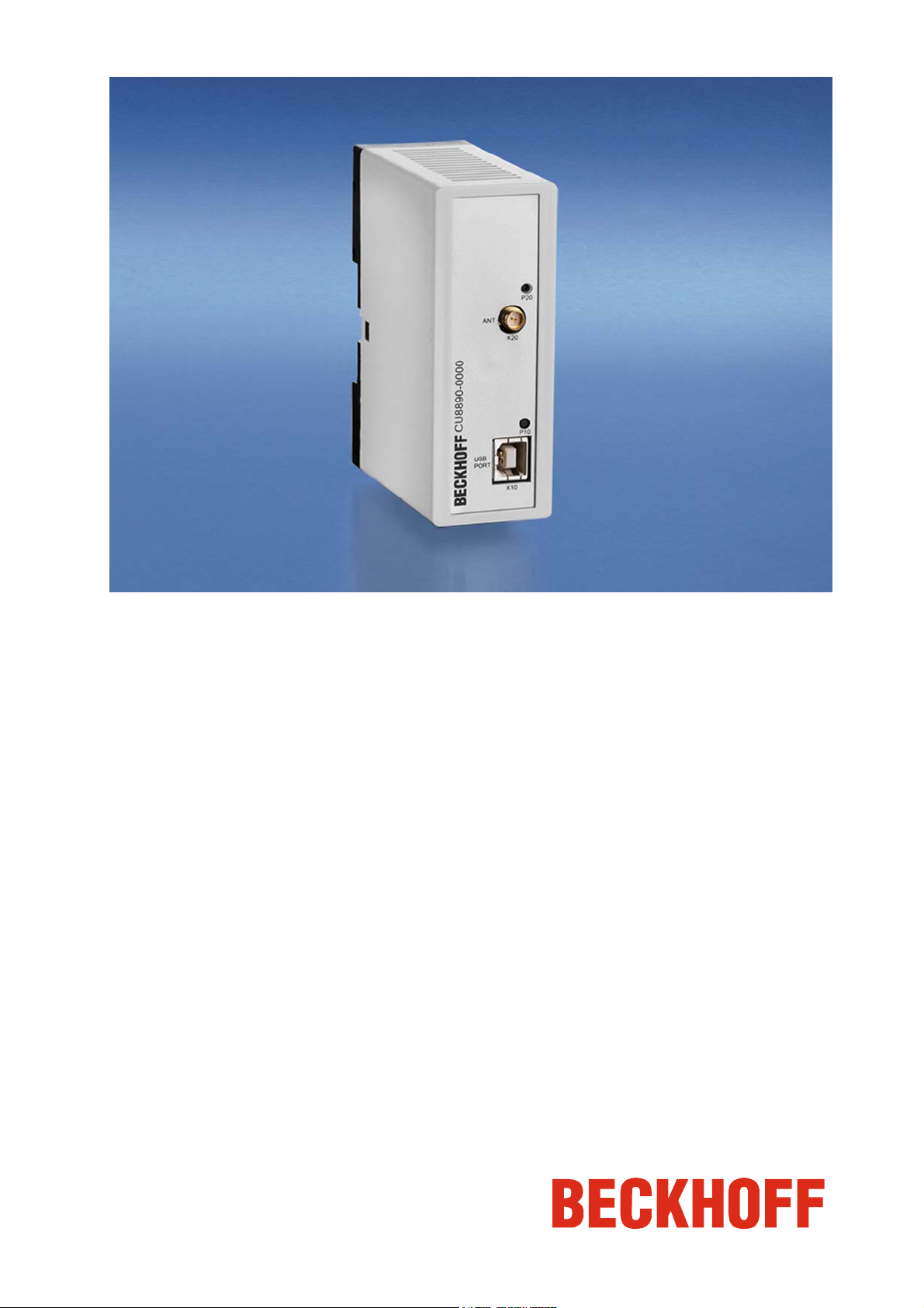
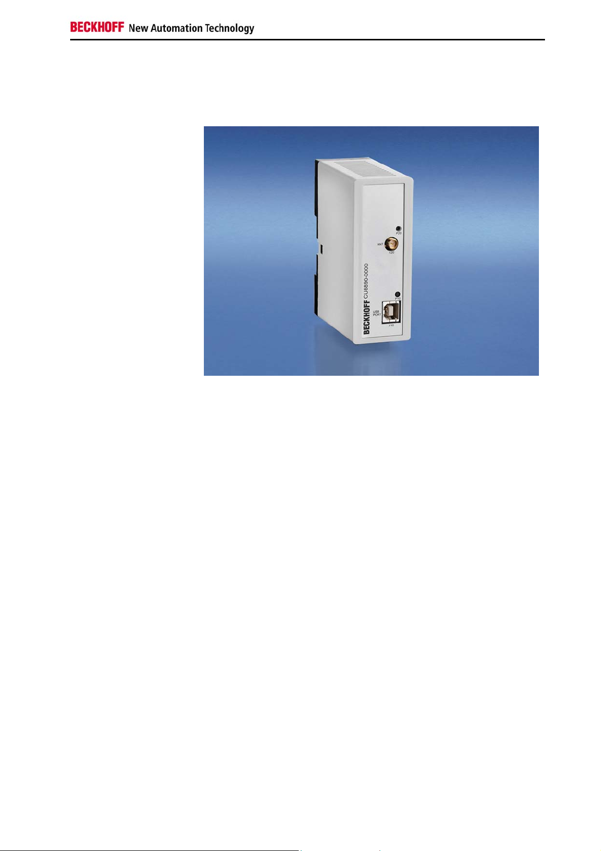
Product Description
Product Overview
View of the CU8890-0000
WLAN Controller
The CU8890 WLAN controller is an industrial grade data exchange unit for
radio technology. The CU8890 is based on the standard IEEE 802.11 b/g
and is designed for control cabinet installation. Connected to a Beckhoff
Industrial PC the CU8890 can be used either as access-point or as client.
Client drivers are available for Windows XP, XP Embedded as well as
Windows CE, thus for each Beckhoff IPC as well as the CX-series. These
support also adhoc modus.
With the drivers for Windows XP and XP Embedded, the CU8890 can also
operate as an access-point.
The encryption methods are possible from AES-128 bit up to WPA2, the
module is compatible to Cisco CCX and supports PEAP and LEAP. The
data rate is adapted dynamically up to 54 Mbit/s.
The CU8890 has a reverse SMA plug for connection of various radio
antennas. The free choice of antenna enables adaptation to the respective
environment. Beckhoff offers a complete accessories program of antennas
and cables.
The outdoor range between two modules depends on the environment and
can be up to 300 m.
It is possible to choice between 11 channels in the 2.4 GHz-band while
following the country specific rules. The status and the data transfer are
indicated by LEDs, so providing quick and simply diagnostic.
Other outstanding features are:
• user-friendly installation via integrated top hat rail adapter
• power supply via USB - no supply voltage necessary
• IEEE 802.11 b/g and TCP/ UDP IP standard
• maximum 54 Mbit/s data range
• compact industrial design
• clear quick diagnosis by separate LEDs.
CU8890-0000 5
Page 8
Product Description
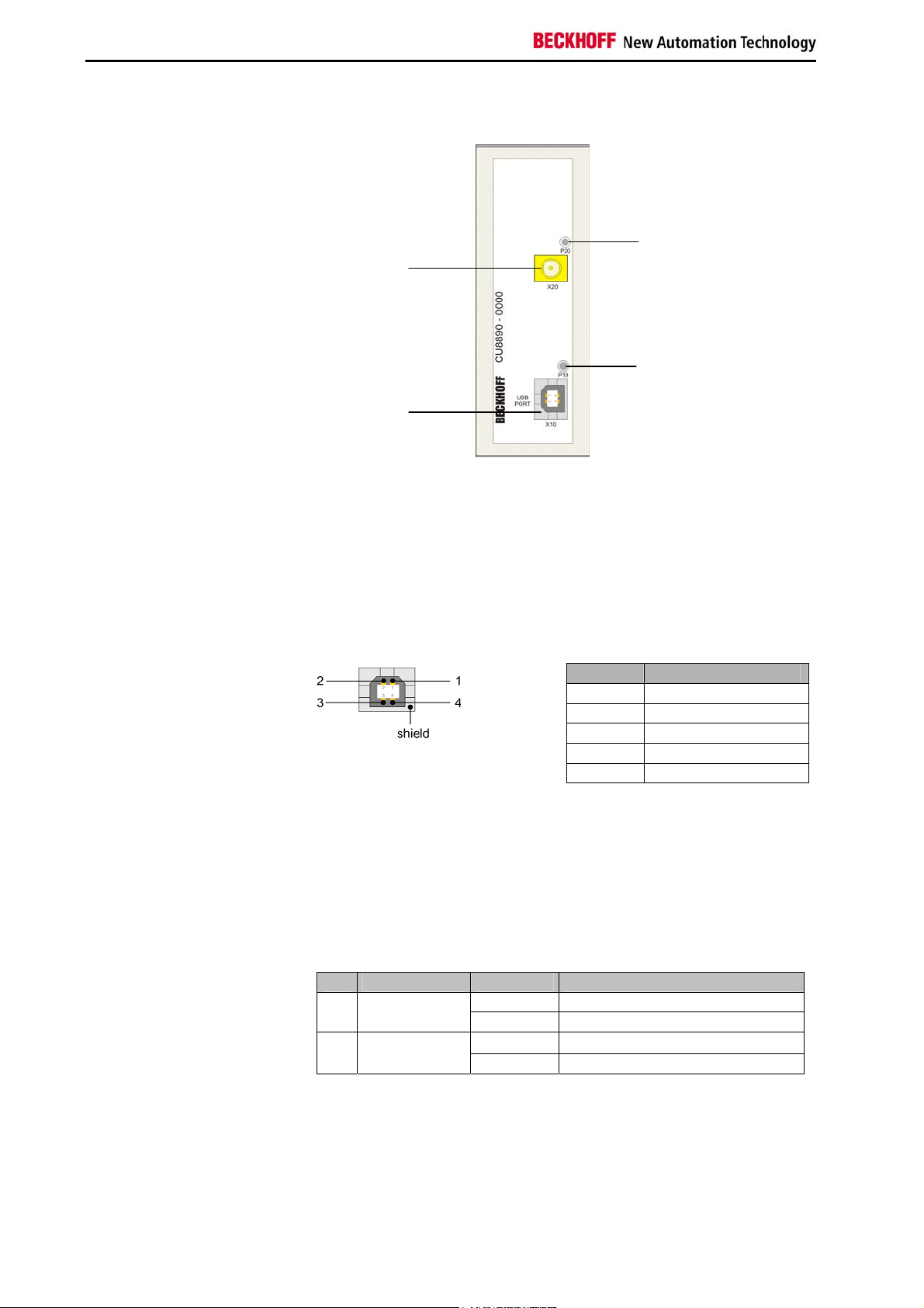
Connectors and LED Diagnostics
View of the connectors and
LED diagnostics
Power Supply
Power supply The power supply is realized by the USB connector.
Data Connector
Data connector The WLAN-Controller CU8890 is connected to the Industrial PC via the
USB Port type B (X10). The pins are described below:
USB Type B Port (X10) (Standard-Cable)
USB Type B Port
X10
Pin Signal
1 VCC
2 Data 3 Data +
4 GND
Shield shield
Antenna Terminal
Antenna terminal The CU8890 has a reverse SMA plug (X20) for connection of various
radio antennas. The free choice of antenna enables adaptation to the
respective environment.
LED-Diagnostic
States for the LEDs The following table shows the possible states for the LEDs:
LED Assignment Status Meaning
off No power supply connected P10 Power LED
lights Power supply via USB Port
off WLAN not active P20 WLAN active
lights WLAN active
6 CU8890-0000
Page 9
Installation Instructions
Installation Instructions
Please also refer to chapter Foreword.
Transport and Unpacking
The specified storage conditions must be observed (see chapter Technical
data).
Transport
Despite the robust design of the unit, the components are sensitive to
strong vibrations and impacts. During transport, the unit should therefore
be protected from excessive mechanical stress. Therefore, please use the
original packaging.
Danger of damage to the unit
Attention
If the device is transported in cold weather or is exposed to extreme
variations in temperature, make sure that moisture (condensation) does not
form on or inside the device.
Prior to operation, the unit must be allowed to slowly adjust to room
temperature. Should condensation occur, a delay time of approximately 12
hours must be allowed before the unit is switched on.
Unpacking
Proceed as follows to unpack the unit:
1. Remove packaging.
2. Do not discard the original packaging. Keep it for future relocation.
3. Check the delivery for completeness by comparing it with your order.
4. Please keep the associated paperwork. It contains important
information for handling the unit.
5. Check the contents for visible shipping damage.
6. If you notice any shipping damage or inconsistencies between the
contents and your order, you should notify Beckhoff Service.
CU8890-0000 7
Page 10
Installation Instructions
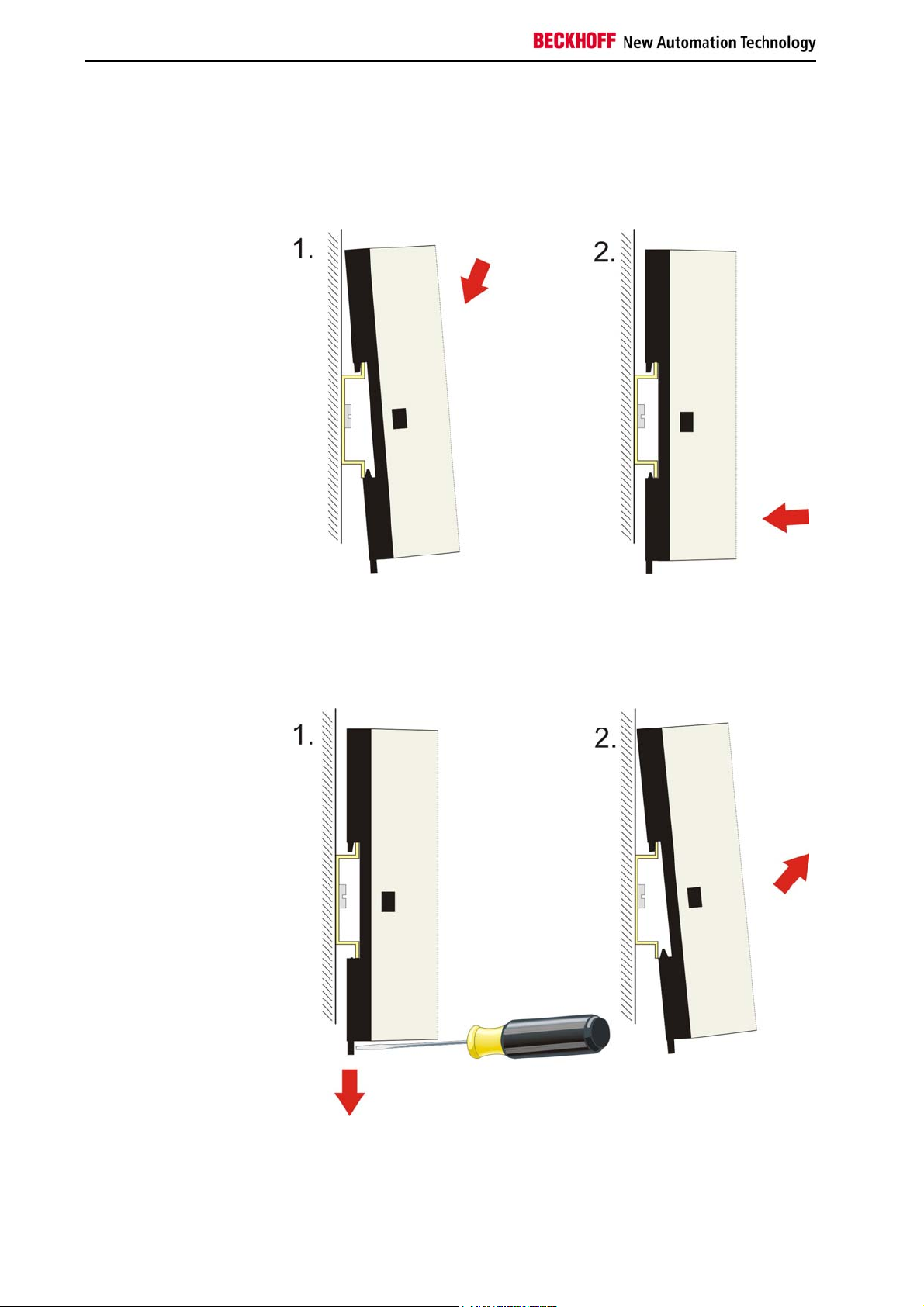
Mounting / Unmounting
The CU8890 can be snapped onto a 35 mm mounting rail conforms to
EN 50022.
Mounting the WLANController
Just push the unit on the upper side under the rail (figure 1) and snap in
the lower side as shown below (figure 2):
Unmounting the WLANController
To release the CU8890 from the mounting rail pull down the locking clip
with a screwdriver (figure 1) and pull off the device from the rail (figure 2):
8 CU8890-0000
Page 11

Installation Instructions
Connecting devices
The power supply plug must be withdrawn
Attention
The connections are documented in the section Product Description.
The power supply is realized by the USB connector.
Please read the documentation for the external devices prior to connecting
them.
During thunderstorms, plug connector must neither be inserted nor
removed.
When disconnecting a plug connector, always handle it at the plug. Do not
pull the cable!
Connecting cables
When connecting the cables to the CU8880, proceed according to the
following sequence:
• Switch off all the devices that are to be connected.
• Disconnect all the devices that are to be connected from the power
supply.
• Connect all the cables between the CU8880 and to the devices
that are to be connected.
• Reconnect all devices to the power supply.
Connecting Power Supply
CU8890-0000 9
Page 12
Operating Instructions
Operating Instructions
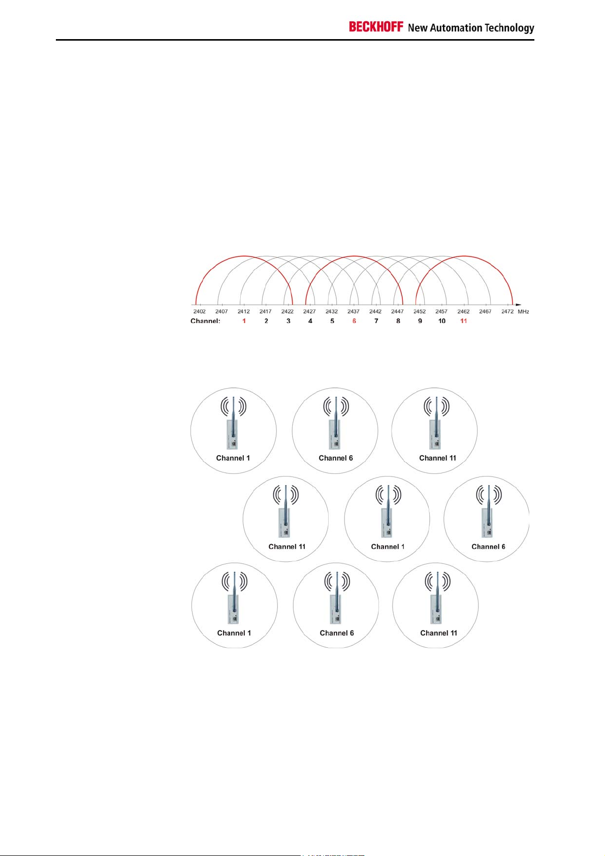
Wireless LANs (WLANs) are local radio networks with main reference to
Channel overlapping
When using the network in a confined area (e.g. in a factory building)
IEEE 802.11 Standard
wireless computer networks. The IEEE 802.11 standard was first published
in 1997.
Basically the standard allows either the wireless connection of two (or
more) PCs (or laptops) with each other directly (adhoc) or to expand an
existing wired computer network with an infrastructure (access points) for
wireless users.
The most popular standard is the IEEE 802.11 b/g that provides a data
transfer rate up to 54 MBit/s for the 2.4 GHz band. The data rate is
adjusted dynamically.
The standard provides 11 channels worldwide, but only 3 can be used
without overlapping:
notice the following comb-shaped structure with a channel difference of 5
channels to each neighbor cell:
Comb-shaped
10 CU8890-0000
Page 13
Operating Instructions
Antennas
The use of the CU8890-0000 is permitted with the following antennas:
Note
Designation Description
ZS6100-0900 Directional antenna (gain 9 dBi), without cable
ZS6200-0400 Omni directional antenna (gain 4 dBi), without cable
ZS6201-0410 Rod antenna (gain 4 dBi), with cable (1 m)
ZS6201-0500 Rod antenna (gain 5 dBi), without cable
Use original Beckhoff accessories
The CE conformity of the CU8890-0000 is only guaranteed if it is operated
with original Beckhoff accessories (antennas, coaxial cable)!
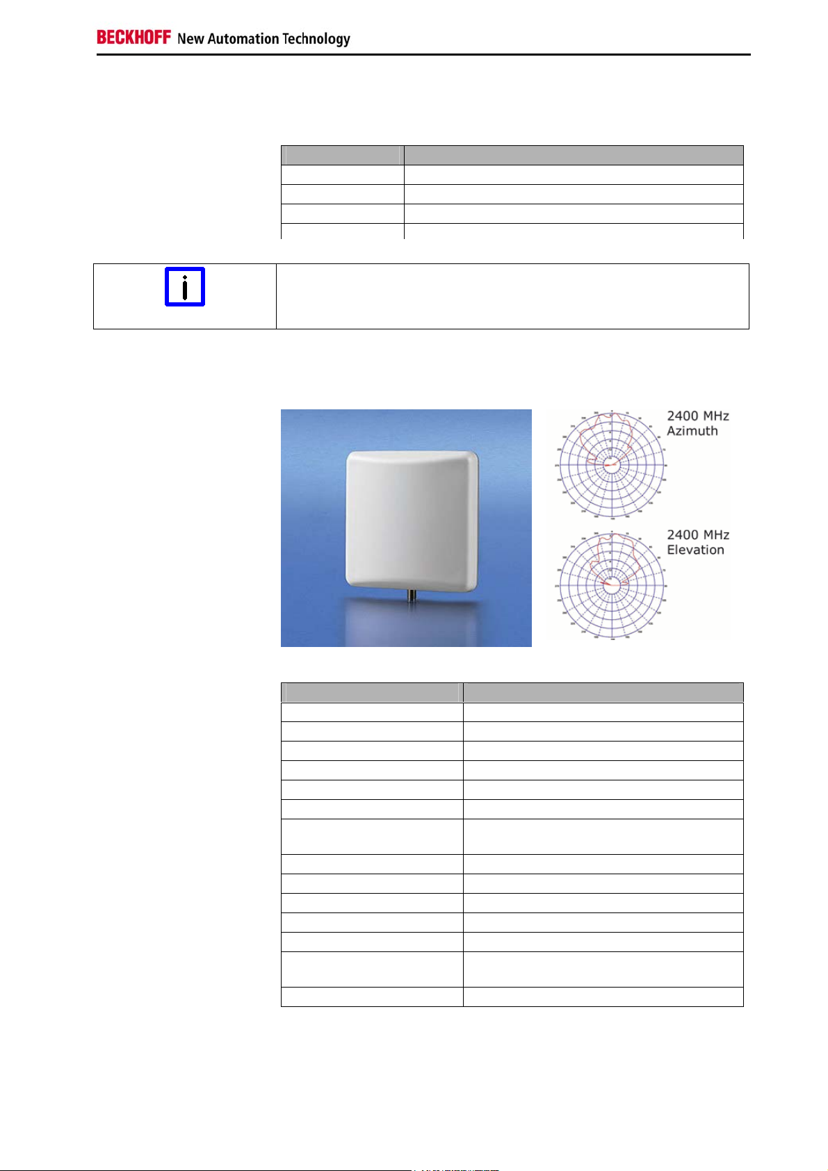
ZS6100-0900
ZS6100-0900
Technical data ZS6100-0900
Frequency range 2400...2485 MHz
Transmission factor 9 dBi
3 dB bandwidth, horizontal 65°
3 dB bandwidth, vertical 65°
Connection SMA socket
Dimensions (W x H x D) 93 mm x 93 mm x 25 mm
Weight (incl. accessories
and packaging)
Operating temperature -40°C ... + 80°C
Relative humidity 95%, no condensation
Protection class IP20
Installation position variable
Approval CE
Mounting
Suitable coaxial cable ZS6000-0102-0020, ZS6000-0102-0040
Approx. 190 g
Bracket mounting, included in scope of
supply
CU8890-0000 11
Page 14

Operating Instructions
ZS6200-0400
ZS6200-0400
Technical data ZS6200-0400
Frequency range 2400...2485 MHz
Transmission factor 4 dBi
3 dB bandwidth, horizontal 360°
3 dB bandwidth, vertical 70°
Connection SMA socket
Dimensions Diameter 110 mm, height 45 mm
Weight (incl. accessories
and packaging)
Operating temperature -40°C ... + 80°C
Relative humidity 95%, no condensation
Protection class IP20
Installation position
Approval CE
Suitable coaxial cable ZS6000-0102-0020, ZS6000-0102-0040
approx. 210 g
variable, predestined for mounting below
the ceiling
12 CU8890-0000
Page 15

Operating Instructions
ZS6201-0410
ZS6201-0410
Technical data ZS6201-0410
Frequency range 2400...2485 MHz
Transmission factor 4 dBi
3 dB bandwidth, horizontal 360°
3 dB bandwidth, vertical 70°
Connection
Dimensions Height 202 mm, foot diameter 35 mm
Weight (incl. cable,
accessories and
packaging)
Operating temperature -40°C ... + 80°C
Relative humidity 95%, no condensation
Mounting Cap nut M14
Protection class IP20
Installation position variable
Approval CE
Coaxial cable 1 m, included in scope of supply
Reverse SMA socket (with 1 m cable,
permanently connected to antenna)
approx. 220 g
CU8890-0000 13
Page 16

Operating Instructions
ZS6201-0500
ZS6201-0500
Technical data ZS6201-0500
Frequency range 2400...2485 MHz
Transmission factor 5 dBi
3 dB bandwidth, horizontal 360°
3 dB bandwidth, vertical 70°
Connection reverse SMA socket
Dimensions Height 195 mm, foot diameter 12 mm
Weight (incl. packaging) approx. 40 g
Operating temperature -40°C ... + 80°C
Relative humidity 95%, no condensation
Mounting Direct connection with hinged joint
Protection class IP20
Installation position variable
Approval CE
Suitable coaxial cable Not required, direct connection
Coaxial Cable
Coaxial cables The following coaxial cables are available:
14 CU8890-0000
Designation Description
ZK6000-0102-
0020
ZK6000-01020040
Coaxial cable, characteristic impedance 50 Ω,
preassembled plug connectors (SMA plug and
reverse SMA socket), black, 2 m
Coaxial cable, characteristic impedance 50 Ω,
preassembled plug connectors (SMA plug and
reverse SMA socket), black, 4 m
Page 17

Operating Instructions
Antenna alignment
Please pay attention to the directional characteristics and polarization of
the antennas in order to mount and align them to each another optimally!
Directional characteristic Omni directional antennas
ZS6201-0410, ZS6201-0500
Design form Side view
(vertical directional
characteristic)
Top view
(horizontal directional
characteristic)
Predestined for mounting
below the ceiling.
ZS6200-0400
Design form Side view
(vertical directional
characteristic)
Directional characteristic directional antennas
ZS6100-0900
Design form Side view
(vertical directional
characteristic)
Top view
(horizontal directional
characteristic)
Top view
(horizontal directional
characteristic)
CU8890-0000 15
Page 18

Operating Instructions
Alignment examples
Align the antennas so that each lies within the radiation cone of the
opposite antenna.
Two ZS6201-0410 or ZS6201-0500
Two ZS6100-0900
Omni directional antennas
Directional antennas
e.g. one ZS6201-0410 and two ZS6100-0900
For optimum transmission, all antennas used must have the same
Care must also be taken when using omni directional antennas that the
Arrows marked with the letters H and V are located on the rear side of the
Mount the antennas such that they can radiate freely!
Mixed operation
Polarization
polarization.
Omni directional antennas
antennas used have the same polarization.
Omni directional antennas such as the ZS6201-0410, ZS6201-0500 or
ZS6200-0400 are mostly mounted for vertical polarization.
Directional antennas
housing of the ZS6100-0900 directional antenna in order to identify the
polarization
Mount the directional antennas such that the marked arrows of all the
antennas used correspond to one another.
Placement of the antennas
There must be no obstructions in the direct vicinity of the antenna that
could hinder the development of the Fresnel zone. Metal obstacles such as
control cabinets, machine parts, pipelines, iron beams etc. particularly
hinder the development of the Fresnel zone!
The connection of the antennas to the CU8890 via the RSMA plug and
coaxial cable enables the antenna to be mounted remotely, so that you can
position the antenna optimally.
16 CU8890-0000
Page 19

Operating Instructions
Attenuation and range
Fresnel Zone
Fresnel Zone In radio transmission, the space between the transmitting and receiving
antennas is known as the Fresnel zone. The Fresnel zone is a notional
spheroid between the antennas.
The main portion of the energy is transmitted in the area of the Fresnel
zone.
This zone should be free of obstructions (e.g. objects, houses, trees etc.).
Metal obstacles such as control cabinets, machine parts, pipelines, iron
beams etc. particularly hinder the development of the Fresnel zone!
Each hindrance of the Fresnel zone attenuates the transmission. If the
Fresnel zone is half obscured, for example, the additional attenuation is 6
dB, i.e. the field strength is reduced to half of the free field value. Reception
may then be disturbed or completely interrupted under certain
circumstances.
If the Fresnel zone is free from obstructions, the propagating wave is only
attenuated by the free field attenuation.
Radius r of the Fresnel zone in relationship to the distance s.
Attenuation in practice
Attenuation With an attenuation of 6 dB the range is shortened to half of the value for
an unobstructed connection, with 12 dB it is shortened to a quarter.
Material Attenuation Range approx.
Thin wall 2-5 dB
Wooden wall 5 dB (free field range)/2 140 m
Masonry wall 6-12 dB
(free field range)/1.5 (free field range)/2
(free field range)/2 (free field range)/4
Example for an
unobstructed range
of 280 m
180 m - 140 m
140 m - 70 m
Concrete wall 10-20 dB
Concrete ceiling 20 dB (free field range)/8 < 35 m
(free field range)/4 (free field range)/8
70 m - 5 m
CU8890-0000 17
Page 20

Operating Instructions
Ranges for a selection of the following antenna combinations
The given ranges are based on an unobstructed view and adherence to the
Fresnel zone.
Two omni directional antennas
Omni directional antennas combined with a directional antenna
Two directional antennas
18 CU8890-0000
Page 21

Examples of Use
Operating mode: CU8890 as Client
Client Modus
Operating mode: CU8890 as Access Point
Access Point Modus
CU8890-0000 19
Page 22

Software installation
Software installation
Note
Note
The XP/ XPe driver for the CU8890 WLAN Controller can be found on the
Download the up-to-date
driver
Installation under Windows XP
Installation
Install the software before connecting the CU8890 WLAN-Controller!
Deactivate the firewall
During installation the firewall should be deactivated.
Beckhoff driver CD / DVD.
The up-to-date driver may be downloaded also from the Internet under:
ftp://ftp.beckhoff.com/Software/embPCControl/XPe/Solutions/CUxxxx_Driver/CU8890_XP_Driver.zip
or
http://www.beckhoff.de/download/Software/embPCControl/XPe/Solutions/CUxxxx_Driver/CU8890_XP_Driver.zip
After execute the setup.exe file the installation routine of Ralink opens:
20 CU8890-0000
Page 23

Software installation
Accept the terms of the license agreement and click Next. The installation
procedure will now ask for the configuration tool you prefer:
Select Microsoft Zero Configuration Tool and click Next to continue.
Change to Ralink Configuration Tool
Note
After the installation has finished you can always change to the Ralink
Configuration Tool.
At the window Setup Type choose Optimize for WiFi mode and go on by
clicking onto Next::
CU8890-0000 21
Page 24

Software installation
Click Install to start the installation procedure. The required data will now
be copied to the hard disk.
Click Finish and the installation is completed:
In the task bar of your computer you now
see the crossed Ralink symbol that indicates
an inactive USB connection.
Connecting USB cable Connect now the CU8890 WLAN controller with your computer via the
USB cable.
When the USB connection is active you
see the following symbol in the task
bar:
22 CU8890-0000
Page 25

Software installation
The installation of the Ralink driver is completed successfully.
Default mode
Note
Generally the CU8890 WLAN controller is in client modus.
After successfully installation under Windows XP the Ralink module is
generally in client modus.
Operating the CU8890 as Client
Configuration with Microsoft Zero Configuration Tool
Change to Microsoft Zero Configuration Tool
Note
Via double click the onto Zero
If you didn't choose the Microsoft
Zero Configuration Tool as it was
recommended during setup, we
recommend now to do this via a
right mouse click onto the Ralink
symbol within the task bar:
Configuration Tool Symbol you can
start the Zero Configuration Tool:
Choose View Wireless Networks to get a list of the available networks:
CU8890-0000 23
Page 26

Software installation
A window with a list of the available networks opens:
Via double click the desired network a connection to this is made.
If a network key is necessary you will be requested to enter it:
Enter the key and click to Connect to connect with this network.
24 CU8890-0000
Page 27

Software installation
Configuration with RaUI-Client Configuration Tool
The configuration can alternatively also be done with the Ralink Tool.
Double click the Ralink Symbol at the Task bar to start the RaUI-Client
Configuration-Tool.
RaUI-Client Configuration Tool for experienced users
Note
We recommend the RaUI-Client Configuration Tool only to experienced
users! To operate this tool a monitor resolution of 1024 x 768 pixel is
necessary.
With the RaUI-Client Configuration Tool in client mode the visible networks
can be sorted in order of channels what may be useful for coexistence
planning. Also the operation as an Access Point-Betrieb is only possible
with this. Details in chapter Operating the CU8890 as Access Point.
Double click on the Ralink symbol in the
task bar starts the RaUI-Client
configuration tool.
To connect to an existing network select the register Network in the RaUI-
Client configuration tool. A list of the available WLANs is shown:
Click Rescan to refresh the list:
CU8890-0000 25
Page 28

Software installation
Click on the button Channel to get a list of the networks sorted by
channels.
Multiple networks
Note
If multiple networks are on one channel, a bad performance can be
possible and you should change the channel!
Connecting the WLAN-Controller
The blue arrow in the network window symbolize the active connection.
Click on the network to select it.
Now the System Config window appears and you can give a profile name
to the selected network:
In the next window you can select the encryption method. Therefore click
on the register Auth.\Encr.:
You now see a list of the selectable encryption methods. On top of the list
the method Open is shown, that means no encryption.
If there is an encryption in the actual network, it now can be selected. In
our example it is WPA-PSK (WPA2-PSK recommended).
26 CU8890-0000
Page 29

Software installation
Type the WPA preshared key and confirm with OK.
Now the view changes to the Profile window and you can see the new
profile:
Click on you profile and the Activate button to activate the network.
The WLAN-Controller now has a network IP-Address shown in the status
messages:
CU8890-0000 27
Page 30

Software installation
Now the network connection is also shown in the standard Windows
network diagram:
28 CU8890-0000
Page 31

Software installation
Operating the CU8890 as Access Point
Access point operation is not possible under Windows CE
Note
By default the CU8890 WLAN-Controller is in client modus. Access point
operation is also only possible under XP/ Xpe, but not under Windows CE.
Access point operation is only possible with Ralink RaUI
Configuration Software
Note
Access point operation is only possible with Ralink RaUI Configuration
Software, but not with the Microsoft Zero Tool. A display resolution of
1024*768 pixel is required for configuration the Ralink RaUI Configuration
Software.
When the CU8890 should be
operated as access point you can
change the mode by right mouse
click on the Ralink symbol in the
task bar:
The symbol in the task bar has now be changed
into AP:
The window Internet Connection Sharing (ICS) appears:
Select the WAN adapter and click OK. The Ralink Wireless Utility window
appears and you can type the network name (SSID) and the channel.
Click Apply and the alignments will be saved.
CU8890-0000 29
Page 32

Software installation
Modification of the network name (SSID)
Note
The modification of the network name (SSID) is not applied until the WLAN
adapter is deactivated and then activated again after changing the name.
Changing the channel without deactivating/ activating is not possible.
Click the button Security Settings to open the security settings window.
Here you can select the designated encryption mode (e.g. WPA-PSK,
suggested) and assign the according key.
The network is not encrypted if you select Open.
30 CU8890-0000
Page 33

Software installation
The CU8890 WLAN-Controller now provides the network with the network
name (SSID) on the selected channel. WLAN clients can now connect to
the network. If a network key was assigned under data encryption options it
must be published to the clients.
CU8890-0000 31
Page 34

Software installation
General Installation Instructions
TwinCAT Real-Time-System
TwinCAT With the CU8890, TwinCAT network variable swapping is possible on base
of UDP/IP (Publisher/ Subscriber Variables).
For installation the CU8890 ethernet adapter for TwinCAT, run the manual
installation via the windows network settings, do not use the system
manager.
Proceed as follows:
1. Select Windows Network Settings
2. Select Wireless LAN
3. Right mouse click for Properties
4. Click Install
5. Add Service
6. Select the manufacturer: Beckhoff
7. Network protocol TwinCAT RT-Ethernet Intermediate Driver
8. Click OK to finish.
In the TwinCAT system manager the wireless network interface is listed
under the category installed devices (system manager -> options -> list
real-time ethernet compatible devices).
Then TwinCAT network variable swapping is possible on base of UDP/IP.
It is not possible to run RT-Ethernet protocol or EtherCAT!
Operation with Windows Firewall
Windows Firewall When operating the wireless network while Windows firewall is activated
the access point mode can be blocked. In that case deactivate the firewall.
32 CU8890-0000
Page 35

Software installation
Windows CE
Windows CE Under Windows CE the operation of the CU8890 WLAN-Controller is only
possible in client mode.
The Windows CE driver is available for CE 6. You can download the driver
for Beckhoff x86- and ARM based devices under:
ftp://ftp.beckhoff.com/Software/embPCControl/CE/Solutions/CUxxxx_Driver/CU8890_CE60.zip
For operating the CU8890 WLAN-Controller you need the CE driver as well
as the Microsoft Zero tool for configuration the WLAN. On x86 based
devices this is already integrated in the CE 6 image. On ARM based
devices the installation has to be started later on.
Proceed as follows:
ARM based devices
Driver Installation on ARM based Devices
Proceed as follows to install the drivers:
1. Download and unpack file CU8890_CE60.zip.
There are two sub-folders for the particular systems x86 or ARM.
2. Copy the files of the selected system (x86 or ARM) to the CE
device (via USB stick, public folder or FTP folder)
3. Copy the files to the correct folders:
\Hard Disk\System:
xcopy all files to device under \hard disk\System
\Hard Disk\RegFiles:
xcopy all files to device under \hard disk\Regfiles
4. Double click on all new Registry Files
5. Finally reboot the system.
After rebooting the system, the driver is installed, as well the Microsoft Zero
Tool at ARM based devices.
Connecting with the
network
Connecting with the network
In the graphical user interface you can select a network. Click connect to
connect with the network:
CU8890-0000 33
Page 36

Appendix
Appendix
Assembly dimensions
The product is characterized by small overall installed size. With a height of
approx. 100 mm, the module dimensions exactly match those of the
Beckhoff Bus Terminals. Together with the lowered connector surfaces,
this means that it can be used in a standard terminal box with a height of
120 mm.
34 CU8890-0000
Page 37

Appendix
Technical data
Input USB-2.0 input with USB-B connector
Antenna terminal Connection via a reverse SMA plug (RP-SMA)
Standard IEEE 802.11 b/g and TCP/ UDP IP
Data transfer rate max. 54 Mbit/s (in adhoc mode max. 11 Mbit/s)
Data transmission band 2,4 GHz
Channels 11
Channel separation 5 MHz
Channel width 22 MHz
Available Worldwide
Data rate adjustment
Dynamic data rate adjustment at mode b: 1, 5, 11 Mbit/s;
at mode g: 6, 9, 12, 18, 24, 36, 48, 54 Mbit/s.
Not usable for Realtime Ethernet or EtherCAT!
Encryption 64-/128-Bit-encryption, WEP, WPA, WPA2
Cisco-compatible extension CCX, providing PEAP and LEAP
Power supply Power supply via USB input connector (5 V
DC
)
The following conditions must be observed during operation:
Environmental conditions Ambient temperature: 0 to 55°C (operation)
-25°C to +70°C (transport/ storage)
Atmospheric humidity: Maximum 95%, non-condensing
Vibration/ Shock resistance EN 60068-2-6 / EN 60068-2-27, EN 60068-2-29
EMC resistance burst/ ESD EN 60000-6-2
Burst: EN 60000-6-4, EN 300328 V1.7.1
Safety of persons in electromagnetic fields: EN 50371:2002
Protection class IP20
Do not use the CU8890 in
The WLAN Controller may not be used in areas of explosive hazard.
areas of explosive hazard
Dimensions (W x H x D) app. 35 mm x 98 mm x 77 mm (with mounting for DIN rail)
Weight app. 90 g
Assembly on 35 mm mounting rail conforms to EN 50022
Installation position any
Approvals CE, FCC, IC
Use original Beckhoff accessories
Note
The CE conformity of the CU8890-0000 is only warranted when operated
with original Beckhoff accessories (see chapter Antennas)
The CU8890-0000 meets demands of the EN 300328 V1.7.1 and is
approvable in all countries of the EU as well as Liechtenstein, Switzerland,
Ireland and Iceland.
The CU8890-0000 meets also demands of FCC Part 15.4 and Canada IC.
More countries on request.
CU8890-0000 35
Page 38

Appendix
Certificates
Grant of Equipment Authorization
36 CU8890-0000
Page 39

Appendix
Technical Acceptance Certificate
CU8890-0000 37
Page 40

Appendix
CE Declaration of Conformity
38 CU8890-0000
Page 41

Appendix
Operation Notes for USA/Canada
Beware of unapproved and unauthorized modifications
Note
Changes or modifications not expressly approved by the manufacturer
could void the user's authority to operate the equipment.
The manufacturer is not responsible for any radio or TV interference
caused by unauthorized modifications to this equipment. Such
modifications could void the user's authority to operate the equipment.
Consider Health Canada limits for the general population!
CAUTION
The installer of this equipment must ensure that the antenna is located or
pointed such that it does not emit RF field in excess of Health Canada
limits for the general population; consult Safety Code 6, obtainable from
Health Canada's website http://www.hc-sc.gc.ca/rpb.
FCC ID and IC ID
FCC ID: XS3 – FC9891-0000
IC ID: 8573A – FC98910000
FCC: Federal Communications Commission Radio Frequency
Interference Statement
This Device complies with Part 15 of the FCC Rules. Operation is subject
to the following two conditions:
(1) This device may not cause harmful interference, and
(2) This device must accept any interference received, including
interference that may cause undesired operation
CU8890-0000 39
Page 42

Appendix
Calculating with decibels
In communication technology power is expressed in decibels (dB), a tenth
of the unit Bel. It is the logarithmic ratio between two quantities with the
same unit.
A reference variable (P1), e.g. a milliwatt (mW) is compared with the
measured variable (P2). The logarithmic correlation was discovered by
Alexander Graham Bell, in whose honor the unit Bel was named.
Since the number values would be too unwieldy if the Bel was used, it was
agreed to use 1/10 of the value, i.e. the decibel.
Definition of the level difference: Level difference [dB] = 10 log ([P1] / [P2]).
Definition of a power ratio: power ratio = 10
level difference/10
The advantage of expressing the powers and losses (attenuations) in dB is
that the calculation method for power ratios can be replaced by a lower
alculation method for the dB calculation. c
Power ratio dB calculation
Multiplication or Division Addition or subtraction
Exponent Factor
Examples of power ratios:
Factor Amplification [dB]
x 1 +0 dB
x 1,25 +1 dB
x 2 +3 dB
x 4 +6 dB
x 10 +10 dB
x 16 +12 dB
x 100 +20 dB
x 1000 +30 dB
E xamples of calculations with decibels:
Change in dB
Factor Attenuation [dB]
x 1 -0 dB
x 0,8 -1 dB
x 0,5 -3 dB
x 0,25 -6 dB
x 0,1 -10 dB
x 0,6 -12 dB
x 0,01 -20 dB
x 0,001 -30 dB
10 / 2 = 5 10 – 3 = 7
2 x 2 x 2 = 8 3 + 3 + 3 = 9
2 x 100 = 200 3 + 20 = 23
1000 / 2 = 500 30 – 3 = 27
40 CU8890-0000
Page 43

Appendix
Beckhoff Support & Service
Beckhoff and their partners around the world offer comprehensive support
and service, guaranteeing fast and competent assistance with all questions
related to Beckhoff products and system solutions.
Beckhoff branches and partner companies
Please contact your Beckhoff branch office or partner company for local
support and service on Beckhoff products!
The contact addresses for your country can be found in the list of Beckhoff
branches and partner companies: www.beckhoff.com
You will also find further documentation
Beckhoff Headquarters
Beckhoff Automation GmbH
Eiserstraße 5
33415 Verl
Germany
Phone: +49(0)5246/963-0
Fax: +49(0)5246/963-198
e-mail: info@beckhoff.com
Beckhoff Support
Beckhoff offers you comprehensive technical assistance, helping you not
only with the application of individual Beckhoff products, but also with wide-
ranging services:
• worldwide support
• design, programming and commissioning of complex automation
systems
• training program for Beckhoff system components
Hotline:
Fax: +49(0)5246/963-9157
e-mail: support@beckhoff.com
+49(0)5246/963-157
Beckhoff Service
The Beckhoff service center supports you in all matters of after-sales
service:
• on-site service
• repair service
• spare parts service
• hotline service
Hotline:
Fax: +49(0)5246/963-479
e-mail: service@beckhoff.com
Quote the project number If servicing is required, please quote the project number of your product.
+49(0)5246/963-460
for Beckhoff components there.
CU8890-0000 41
 Loading...