

Page 1
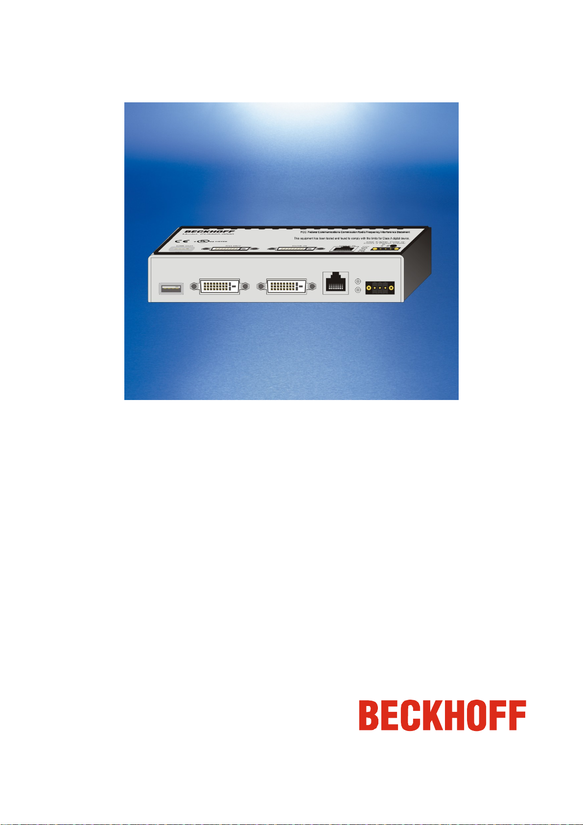
CU8860-0000
USB-Extender-Rx
(USB and DVI Extender)
Version: 0.3
Date: 2006-02-20
Page 2

Table of Contents
Table of Contents
1 Foreword 1
1.1 Notes on the documentation 1
1.1.1 Liability Conditions 1
1.1.2 Conditions of delivery 1
1.1.3 Copyright 1
1.2 Safety Instructions 2
1.2.1 State at Delivery 2
1.2.2 Description of safety symbols 2
2 Product Overview 3
2.1 Introduction 3
2.2 Technical Data 4
2.3 Dimensions 5
3 Installation 6
3.1 Installing USB-cable strain relief 6
3.2 Mounting / Unmounting 6
3.2.1 Mounting on a planar surface 6
3.2.2 Mounting on a 35 mm C mounting rail 8
3.3 Power Supply 9
3.3.1 UL requirements 9
3.4 Data - Connectors 10
3.5 LED Diagnostics 11
3.6 Architecture Description 12
4 Approvals for USA and Canada 14
4.1 FCC Approval for USA 14
4.2 FCC Approval for Canada 14
5 Appendix 15
5.1 BECKHOFF support and service 15
5.1.1 BECKHOFF support 15
5.1.2 BECKHOFF service 15
5.2 BECKHOFF headquarters 15
CU8860-0000
Page 3

Foreword
1 Foreword
1.1 Notes on the documentation
This description is only intended for the use of trained specialists in control and automation engineering who are
familiar with the applicable national standards. It is essential that the following notes and explanations are followed
when installing and commissioning these components.
1.1.1 Liability Conditions
The responsible staff must ensure that the application or use of the products described satisfy all the requirements
for safety, including all the relevant laws, regulations, guidelines and standards.
The documentation has been prepared with care. The products described are, however, constantly under
development. For that reason the documentation is not in every case checked for consistency with performance
data, standards or other characteristics. None of the statements of this manual represents a guarantee (Garantie)
in the meaning of § 443 BGB of the German Civil Code or a statement about the contractually expected fitness for
a particular purpose in the meaning of §434 par.1 sentence 1 BGB. In the event that it contains technical or
editorial errors, we retain the right to make alterations at any time and without warning. No claims for the
modification of products that have already been supplied may be made on the basis of the data, diagrams and
descriptions in this documentation.
1.1.2 Conditions of delivery
Furthermore the general conditions of delivery of company Beckhoff Automation GmbH apply.
1.1.3 Copyright
© This documentation is copyrighted. Any reproduction or third party use of this publication, whether in whole or in
part, without the written permission of Beckhoff Automation GmbH, is forbidden.
CU8860-0000 1
Page 4
Foreword
1.2 Safety Instructions
1.2.1 State at Delivery
All the components are supplied in particular hardware and software configurations appropriate for the application.
Modifications to hardware or software configurations other than those described in the documentation are not
permitted, and nullify the liability of Beckhoff Automation GmbH.
1.2.2 Description of safety symbols
The following safety symbols are used in this operating manual. They are intended to alert the reader to the
associated safety instructions.
Danger
Warning
Note
This symbol is intended to highlight risks for the life or health ofpersonnel.
This symbol is intended to highlight risks for equipment, materials or the environment.
This symbol indicates information that contributes to better understanding.
CU8860-0000 2
Page 5
2 Product Overview
2.1 Introduction
Product Overview
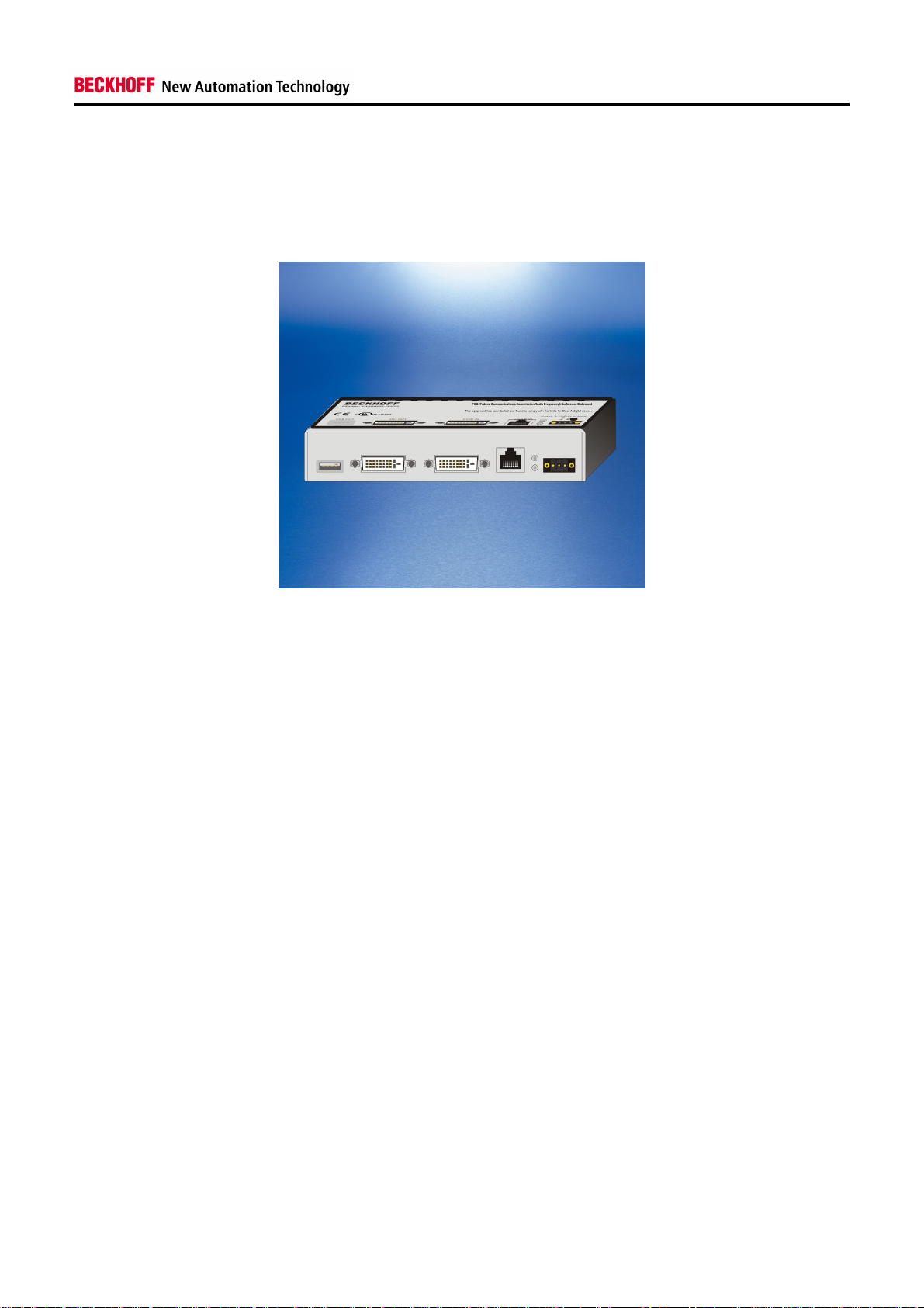
The Beckhoff USB-Extender-Rxallows to extend the limits of USB cable length. Standard USBcable are specified
for cable length up to 5 meters. For some industrial applications there is need for longerdistances. This box can
extend the distance up to 50 meters. This box receive the externded USB signals from sending box CU8800 and
convert them back to USB. It also conditions the DVI video signals. Other outstanding features are:
User-friendly installation via mounting kit
Optional installation via top hat rail adapter
24 VDCsupply voltage –the standard in industrial evironments
12 Mbit, and 1,5 Mbit support for compatibility to all USB1.1 standards
Standard CAT5 network cable for extension
compact industrial design
clear quick diagnosis by separate LEDs for USB and DVI conditi ons
CU8860-0000 3
Page 6
Product Overview
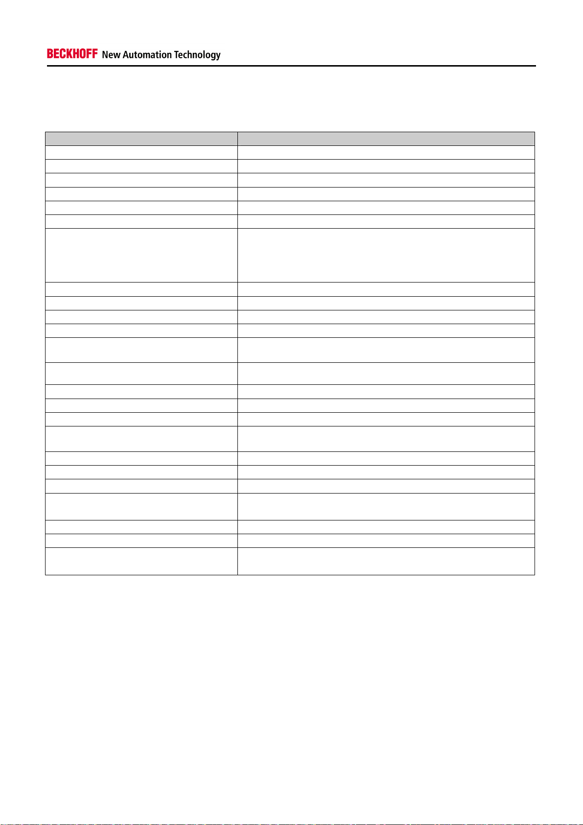
2.2 Technical Data
Product name CU8860-0000
Number of USB type Aports (downstream) 1
Number of USB–Extender-Rxports(RJ45) 1
Number of DVI Input ports 1
Number of DVI Output ports 1
Supported standard DVI, USB 1.1
Supported baud rates USB 12 Mbit (Full Speed), 1,5 Mbit (Low Speed)
Supported Modes DVI 640 x 480 @ 60 Hz,
800 x 600 @ 60 Hz,
1024 x 768 @ 60 Hz,
1280 x 1024 @ 60 Hz
Status display 2 LEDs
USB wiring length (host to extender) maximum 1 meter
USB extension wiring length maximum 50 meters
USB wiring length (extender to hub/device) maximum 5meters
Power supply to USB maximum 100 mA (without additional power supply)
maximum 500 mA (with connected additional power supply)
Additional Power supply
Power consumption 1,15 W
Dimensions (w x h x d) app. 160 mm x 30 mm x 80 mm
Weight app. 360 g
Permissible ambient temperature 0°C to +55°C (operation)
Permissible relative humidity 5% to 95%, no condensation
EMC resistance burst / ESD EN60000-6-2/ EN 60000-6-4
Vibration / Shock resistance EN 60068-2-6 / EN 60068-2-27, EN60068-2-29
Assembly Adapter for mounting on 35 mmmounting rail conforms to EN 50022
Installation position any
Protection class IP20
Approvals CE
24 V DC (-15% to +20%), protected against polarity reversal.
To meet the UL requirements use 4 A fuse or class 2 power supply!
-25°C to +70°C (transport/storage)
Adapter plate for mounting on planar surfaces
UL (see chapter UL requirements)
CU8860-0000 4
Page 7

2.3 Dimensions
Product Overview
CU8860-0000 5
Page 8

Installation
3 Installation
3.1 Installing USB cable strain relief
All plugs, connected to the unit, have an integrated stain relief, except the USB plug. To provide the USB plug from
disconnecting, a bracket must be installed on the front of the unit. The bracket has the following measures:
The bracketis fixed with a screw (M3, 4 mm). The USB plug will be connected to the unit. The cable is place
through the slot in the middle of the bracket. (see picture)
3.2 Mounting / Unmounting
The USB-Extender-RX CU8860-0000 can be installed in two ways. There are two versions of mounting kits to
install the unit (a) onto a planar surface or (b) onto a 35 mmmounting rail that conforms to EN 50022.
3.2.1 Mounting on a planar surface
First the installation on planar surfaces is described.The kit has the following measures:
CU8860-0000 6
Page 9

Installation
It will be fixed on the backside of the unit with four screws (4 x M3, 4 mm). The four notches can be used to fix the
unit on the surface. The following picture shows how to fix the plate on the unit.
The device has no restrictions for installation positions. The following picture shows some variations.
CU8860-0000 7
Page 10

Installation
3.2.2 Mounting on a 35 mm mounting rail
Alternative the unit can be installed on a mounting rail. To use this installation option an adapter for the rail is
needed. It can be ordered together with the unit. The adapter is fixed with four screws (M3, 4 mm). The picture
shows the installation position:
The unit is snapped onto the rail as follows:
1. Lower the backside of the installed adapter onto the rail and press it down.
2. Push the unit towards the rail until it snaps in.
To release the CU8860-0000 from the mounting rail:
3. Press down the unit until it gets loose on the rail
4. Pull the unit from the mounting rail
CU8860-0000 8
Page 11

Installation
3.3 Power Supply
The USB-Extender-RxCU8860 can be powered by anadditional power supply(X10). If a USB device needs more
than 100mA the additional power supply must be connected. The pins have to be connected as shown in the
picture below.
3.3.1 UL requirements
Danger
For the compliance of the UL requirements the USB -Extender-Rxshould only be supplied
by a 24 VDCsupply voltage, supplied by an isolating source and protected by means
of a fuse (in accordance with UL248), rated maximum 4Amp.
by a 24 VDCpower source, that has to satisfy NEC class 2.
A class 2 power supply shall not be connected in series or parallel with another
(class 2) power source!
To meet the UL requirements, the USB hub CU8800-0000 must not be connected to
unlimited power sources!
CU8860-0000 9
Page 12

Installation
3.4 Data - Connectors
The connector are 1 USB port Type A, a RJ45-connector and 2 DVI-Socket s. The pins are described below:
USB type A Port (X50) (standard cable)
Pin Assignment
1 VCC
2 Data 3 Data +
4 GND
Shell Shield
RJ 45 Port (X20) (standard CAT5 cable)
Pin Signal Assignment
1 15 V 15 V +
2 GND Ground
3 TX USB TX
4 RX USB RX
5 RX USB RX
6 TX USB TX
7 15 V 15 V +
8 GND Ground
CU8860-0000 10
Page 13

Installation
DVI–D Port (X30 / X40)
Pin Assignment Pin Assignment Pin Assignment
1 TMDS data 2- 9 TMDS data 1- 17 TMDS data 02 TMDS data 2+ 10 TMDS data 1+ 18 TMDS data 0+
3 TMDS data 2/4 Shield 11 TMDS data 1/3 shield 19 TMDS data 0/5 shield
4 not connected 12 not connected 20 not connected
5 not connected 13 not connected 21 not connected
6 DDC clock 14 + 5 V Power 22 TMDS clock shield
7 DDC data 15 ground ( +5V, Analog
H/V Sync)
8 analog vertical sync 16 hot plug detect 24 TMDSclock -
23 TMDS clock +
3.5 LED Diagnostics
The following table shows the possible states for the LEDs:
LED Allocation State Meaning
green current < 500 mAP10 Power load
on USB port
red current > 500 mA
P20 DVI-Link
green DVI signal is connected
(clock signal is sensed)
red DVI signal is not
connected (No clock
signal is sensed)
CU8860-0000 11
Page 14

Installation
3.6 Architecture Description
Within the USB-Extender-TX (CU8800) and USB-Extender-RX (CU8860) the length of USB data transmission can
be increased from35 meters (1 host, 5 USBhubs and a device connected with 5 meters cable) up to61meters.
Due to the USB signal runtime, it is not possible to connect more than one USB hub in the chain. The DVI signals
are extended up to 55 meters. The following pictures show the maximal length of connection for possible
configurations:
This configuration (1) contains no additional USB hub. The maximal distance of extension is 56 meters: 1 meter of
cable to the extension box CU8800; up to 50 metersextension cable and5 meters from extension box to USB
device. The DVI cable can have a maximal length of 50 meters to the extension box. From there the DVI signal can
be transmitted up to 5 meters.
This configuration (2) contains an additional USB hub. The USB hub is connected directly to the host computer.
The maximal distance of extension is 61 meters:5 meters of cable from USB host to the USB hub; 1 meter cable to
the extension box CU8800; up to 50 metersextension cable and 5 meters from extension box to USB device. The
DVI Signal is also extended to maximum 55 meters. (see configuration1)
CU8860-0000 12
Page 15

Installation
The third configuration (3) has nearly the same structure than configuration 2. The USB hub is connected after the
extension. Due to signal quality the maximal distance is 59 meters: 1 meter of cable from USB host to the USB
extension box CU8800; up to 50 meters extension cable; 5 meters from extension box to USB hub and 3 meters of
cable to the USB device. The DVI Signal is also extended to maximum 55 meters. (see configuration1)
CU8860-0000 13
Page 16

Approvals for USA and Canada
4 Approvals for USA and Canada
4.1 FCC Approval for USA
FCC: Federal Communications Commission Radio Frequency Interference Statement
This equipment has been tested and found to comply with the limits for a Class A digital device, pursuant to Part15
of the FCC Rules. These limits are designed to provide reasonable protection against harmful interference when
the equipment is operated in a commercial environment. This equipment generates, uses, and can radiate radio
frequency energy and, if not installed and used in accordance with the instruction manual, may cause harmful
interference to radio communications. Operation of this equipment in a residential area is likely to cause harmful
interference in which case the user will be required to correct the interference at his own expense.
4.2 FCC Approval for Canada
FCC: Canadian Notice
This equipment does not exceed the Class A limits for radiated emissions as described in the Radio Interference
Regulations of the Canadian Department of Communications.
CU8860-0000 14
Page 17

Appendix
5 Appendix
5.1 Beckhoff support and service
Beckhoff and their partners around the world offer comprehensive support and service, making available fast and
competent assistance with all questions related to Beckhoff products and system solutions.
5.1.1 Beckhoff support
Support offers you comprehensive technical assistance, helping you no only with the application of individual
Beckhoff products, but also with other, wide-ranging services:
world-wide support
design, programming and commissioning of complex automation systems
and extensive training program for Beckhoff system components
Hotline: + 49 (0) 5246/963-157
Fax: + 49 (0) 5246/963-9157
e-mail: support@beckhoff.com
5.1.2 Beckhoff service
The BeckhoffService Center supports you in all matters of after-sales service:
on-site service
repair service
spare parts service
hotline service
Hotline: + 49 (0) 5246/963-460
Fax: + 49 (0) 5246/963-479
e-mail: service@beckhoff.com
You will find further support and service addresses on our internet pages under http://www.beckhoff.com.
5.2 Beckhoff headquarters
Beckhoff Automation GmbH
Eiserstr. 5
33415 Verl
Germany
Phone: + 49 (0) 5246/963-0
Fax: + 49 (0) 5246/963-198
e-mail: info@beckhoff.de
Web: www.beckhoff.com
The addresses of Beckhoff’s branch offices and representatives round the world can be found on her internet
pages: http://www.beckhoff.com. You will also find further documentation for Beckhoffcomponents there.
CU8860-0000 15
 Loading...