

Page 1
Installation- and Operating instructions for
DVI Splitter
CU8810-0000
Version: 1.1
Date: 2015-03-25
Page 2

Page 3

Table of contents
Table of contents
1.
General instructions 2
Notes on the Documentation 2
Liability Conditions 2
State at Delivery 2
Description of safety symbols 2
2.
Product Description 3
Product Overview 3
Power supply 4
Data Connectors 4
USB type B Port (X20) (standard cable) 4
RJ 45 Port (X30, X31, X32, X33) (standard CAT5 cable) 4
DVI-IN (X40, X41) (standard DVI cable) 4
DVI-OUT (X50, X51, X52, X53) (standard DVI cable) 5
LED Diagnostics 5
3.
Installation Instructions 6
Transport and Unpacking 6
Transport 6
Unpacking 6
Mounting / Unmounting 7
Connecting devices 8
Connecting cables 8
Check voltage rating and connect 8
4.
Operating Instructions 9
Configuration 9
DIP Switch 1 (SW1) 9
DIP Switch 2 (SW2) 11
DIP Switch 3 (SW3) 12
Architecture Description 13
Version 1 13
Version 2 13
Version 3 13
Version 4 14
5.
Appendix 15
Assembly dimensions 15
Beckhoff Support & Service 16
Beckhoff branches and partner companies 16
Beckhoff Headquarters 16
Beckhoff Support 16
Beckhoff Service 16
Technical data 17
Approvals for USA and Canada 17
FCC: Federal Communications Commission Radio Frequency Interference
Statement 17
FCC: Canadian Notice 17
CU8810-0000 1
Page 4

General instructions
General instructions
Notes on the Documentation
This description is only intended for the use of trained specialists in control
and automation engineering who are familiar with the applicable national
standards. It is essential that the following notes and explanations are
followed when installing and commissioning these components.
Liability Conditions
The responsible staff must ensure that the application or use of the
products described satisfy all the requirements for safety, including all the
relevant laws, regulations, guidelines and standards.
The documentation has been prepared with care. The products described
are, however, constantly under development. For that reason the
documentation is not in every case checked for consistency with
performance data, standards or other characteristics. None of the
statements of this manual represents a guarantee (Garantie) in the
meaning of § 443 BGB of the German Civil Code or a statement about the
contractually expected fitness for a particular purpose in the meaning of
§ 434 par. 1 sentence 1 BGB. In the event that it contains technical or
editorial errors, we retain the right to make alterations at any time and
without warning. No claims for the modification of products that have
already been supplied may be made on the basis of the data, diagrams
and descriptions in this documentation.
© This documentation is copyrighted. Any reproduction or third party use of
this publication, whether in whole or in part, without the written permission
of Beckhoff Automation GmbH & Co. KG, is forbidden.
State at Delivery
i
Danger
Warning
Note
All the components are supplied in particular hardware and software
configurations appropriate for the application. Modifications to hardware or
software configurations other than those described in the documentation
are not permitted, and nullify the liability of Beckhoff Automation GmbH &
Co. KG.
Description of safety symbols
The following safety symbols are used in this operating manual. They are
intended to alert the reader to the associated safety instructions.
This symbol is intended to highlight risks for the life or health of personnel.
This symbol is intended to highlight risks for equipment, materials or the
environment.
This symbol indicates information that contributes to better understanding.
2 CU8810-0000
Page 5
Product Description
Product Description
Product Overview
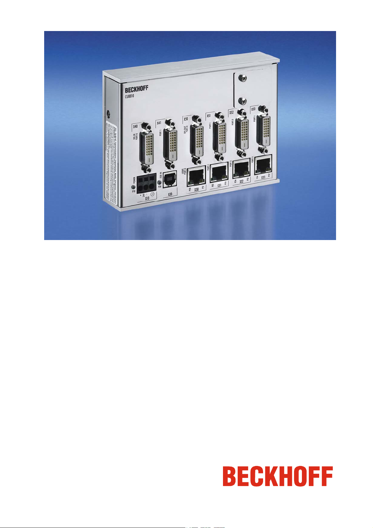
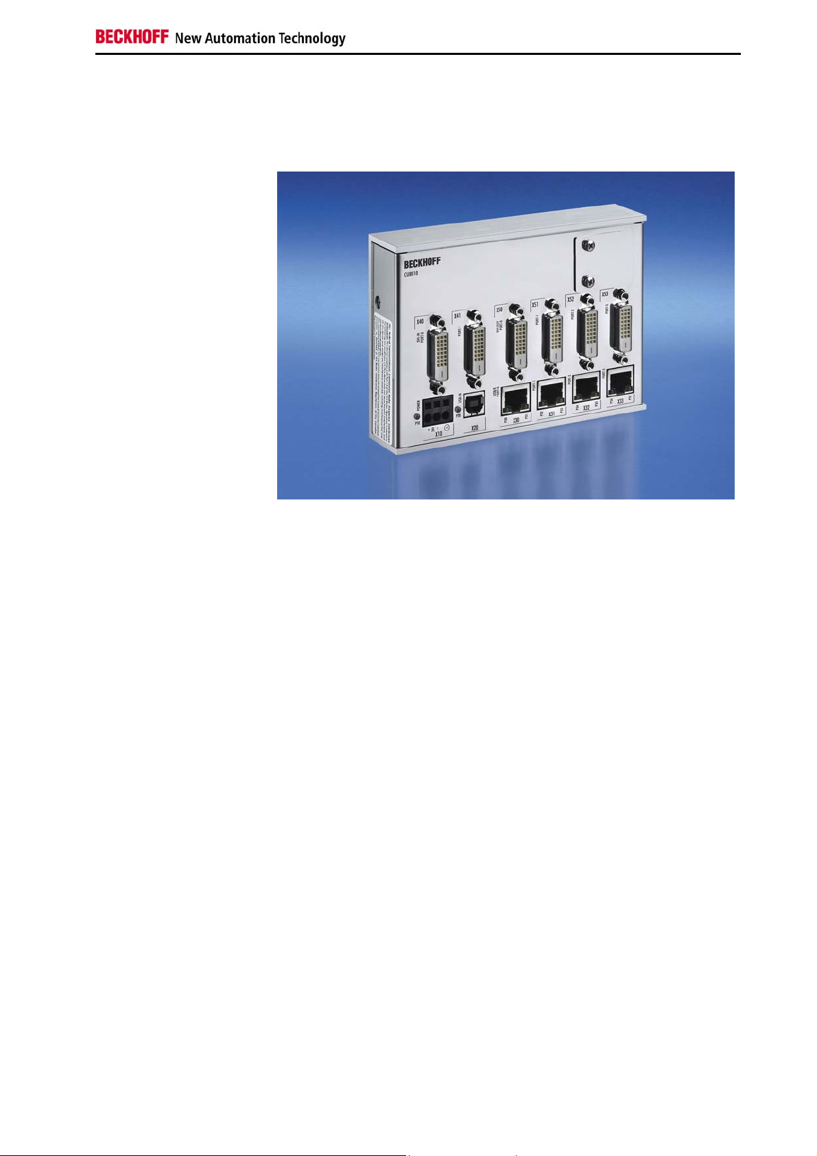
View of the CU8810-0000
DVI splitter
A common application in machine and plant construction is the
simultaneous display of a PC screen on several monitors. Up to four
DVI/USB Control Panels can be connected to a PC via the CU8810 DVI
splitter. Thanks to DVI/USB extension technology, the Control Panels can
each be connected at distances of 50 m from the DVI splitter. PCs with two
DVI outputs, which are configured as extended desktops, generate two
different screen contents. Both DVI outputs can be fed into the DVI splitter.
Using DIP switches, the four DVI outputs can each be assigned to one of
the two DVI inputs, so that the Control Panels show either the left or the
right half of the desktop, as selected. Other outstanding features are:
• User-friendly installation via integrated top hat rail adapter
• 24 V
• 12 Mbit and 1.5 Mbit support for compatibility to the USB1.1 standard
• Standard CAT5 network cable for USB extended
• Compact industrial design
• Clear quick diagnosis by separate LEDs.
supply voltage – the standard in industrial environments
DC
CU8810-0000 3
Page 6
Product Description
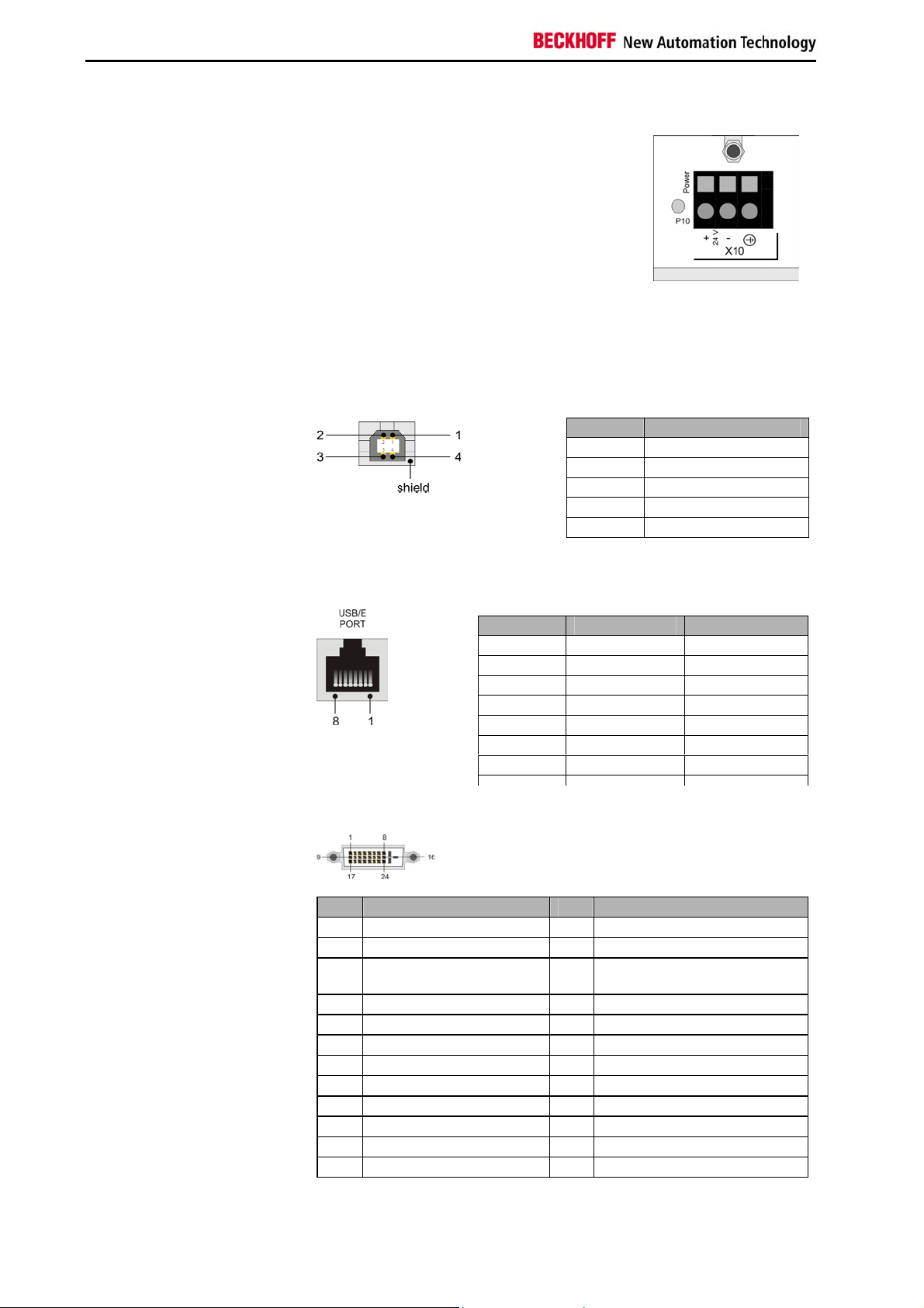
Power supply
24 VDC power supply
The DVI splitter CU8810 will be powered by a
24 V
power supply (X10). The pins have to
DC
be connected as shown on the front panel of
the CU8810 device.
Data Connectors
The CU8810 has three kinds of connectors: USB type B, RJ45 and
DVI. The pin layouts are described below.
USB type B Port (X20) (standard cable)
USB type B Port
RJ 45 Port (X30, X31, X32, X33) (standard CAT5 cable)
Pin Assignment
1 VCC
2 Data 3 Data +
4 GND
Shield Shield
RJ 45 Port
DVI-IN
Pin Signal Assignment
1 15 V 15 V +
2 GND Ground
3 TX USB TX
4 RX USB RX
5 RX USB RX
6 TX USB TX
7 15 V 15 V +
DVI-IN (X40, X41) (standard DVI cable)
Pin Assignment Pin Assignment
1 TMDS Data 2 - 13 Not connected
2 TMDS Data 2 + 14 + 5 V Power
3 TMDS Data 2/4 Shield 15
4 Not connected 16 Hot Plug Detect
5 Not connected 17 TMDS Data 0 6 DDC Clock 18 TMDS Data 0 +
7 DDC Data 19 TMDS Data 0/5 Shield
8 Analog Vertical Sync 20 Not connected
9 TMDS Data 1 - 21 Not connected
10 TMDS Data 1+ 22 TMDS Clock Shield
11 TMDS Data 1/3 Shield 23 TMDS Clock +
12 Not connected 24 TMDS Clock -
Ground ( + 5 V, Analog H/V
Sync)
4 CU8810-0000
Page 7
Product Description
DVI-OUT (X50, X51, X52, X53) (standard DVI cable)
DVI-Out
Pin Assignment Pin Assignment
1 TMDS Data 2 - 13 Not connected
2 TMDS Data 2 + 14 + 5 V Power
3 TMDS Data 2/4 Shield 15
4 Not connected 16 Hot Plug Detect
5 Not connected 17 TMDS Data 0 6 DDC Clock 18 TMDS Data 0 +
7 DDC Data 19 TMDS Data 0/5 Shield
8 Analog Vertical Sync 20 Not connected
9 TMDS Data 1 - 21 Not connected
10 TMDS Data 1 + 22 TMDS Clock Shield
11 TMDS Data 1/3 Shield 23 TMDS Clock +
12 Not connected 24 TMDS Clock -
Ground ( + 5 V, Analog H/V
Sync)
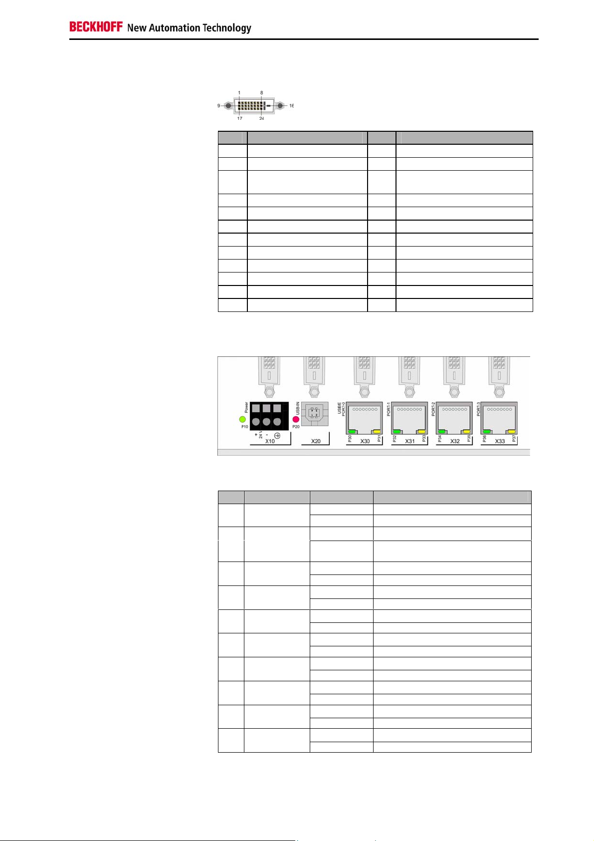
LED Diagnostics
LED Diagnostics
The following table shows the possible states for the LEDs:
LED Assignment Status Meaning
off No power supply connected P10 Power supply
Port
Port 0
Port 0
Port 1
Port 1
Port 2
Port 2
Port 3
Port 3
lights green
off USB is operational P20 USB/IN
lights red USB is in suspend mode/ no device
off No 15 V supplied to USB/E Port P30 USB/E
lights green 15 V supplied to USB/E Port
off No suspend P31 USB/E
lights yellow Suspend
off No 15 V supplied to USB/E Port P32 USB/E
lights green 15 V supplied to USB/E Port
off No suspend P33 USB/E
lights yellow Suspend
off No 15 V supplied to USB/E Port P34 USB/E
lights green 15 V supplied to USB/E Port
off No suspend P35 USB/E
lights yellow Suspend
off No 15 V supplied to USB/E Port P36 USB/E
lights green 15 V supplied to USB/E Port
off No suspend P37 USB/E
lights yellow Suspend
connected
24 V
DC
connected
CU8810-0000 5
Page 8

Installation Instructions
Installation Instructions
Warning
Please also refer to chapter General instructions.
Transport and Unpacking
The specified storage conditions must be observed (see chapter Technical
data).
Transport
Despite the robust design of the unit, the components are sensitive to
strong vibrations and impacts. During transport, the unit should therefore
be protected from excessive mechanical stress. Therefore, please use the
original packaging.
Danger of damage to the unit!
If the device is transported in cold weather or is exposed to extreme
variations in temperature, make sure that moisture (condensation) does not
form on or inside the device.
Prior to operation, the unit must be allowed to slowly adjust to room
temperature. Should condensation occur, a delay time of approximately 12
hours must be allowed before the unit is switched on.
Unpacking
Proceed as follows to unpack the unit:
1. Remove packaging.
2. Do not discard the original packaging. Keep it for future relocation.
3. Check the delivery for completeness by comparing it with your order.
4. Please keep the associated paperwork. It contains important
information for handling the unit.
5. Check the contents for visible shipping damage.
6. If you notice any shipping damage or inconsistencies between the
contents and your order, you should notify Beckhoff Service.
6 CU8810-0000
Page 9

Installation Instructions
Mounting / Unmounting
Mounting the DVI splitter
The CU8810 can be snapped onto a 35 mm mounting rail conforms to
EN 50022.
Just push the unit on the lower side under the rail (1) and snap in the upper
side (2) as shown below:
Unmounting the DVI splitter
To release the CU8810 from the mounting rail push up the unit (3) and pull
off the device from the rail (4):
CU8810-0000 7
Page 10

Installation Instructions
Connecting devices
Warning
The power supply plug must be withdrawn!
Please read the documentation for the external devices prior to connecting
them.
During thunderstorms, plug connector must neither be inserted nor
removed.
When disconnecting a plug connector, always handle it at the plug. Do not
pull the cable!
Connecting cables
The connectors are documented in the section Product Description.
When connecting the cables to the CU8810, proceed according to the
following sequence:
• Switch off all the devices that are to be connected.
• Disconnect all the devices that are to be connected from the power
supply.
• Connect all the cables between the CU8810 and to the devices
that are to be connected.
• Reconnect all devices to the power supply.
Check voltage rating and connect
1. Check that the external power supply is providing the correct
voltage.
2. Connect the unit to your external 24 V
power supply.
DC
8 CU8810-0000
Page 11

Operating Instructions
Operating Instructions
Configuration
Front view
Opening the enclosure
DIP Switch 1 (SW1)
Front view of the CU8810 with
opened enclosure.
The device is configured by a set of three switches. The switches are
covered by an enclosure on the upper right side on the front. To open the
enclosure you need to remove the two screws, as shown below:
There are three DIP switches and two status LEDs covered by the plate.
The detailed functions are described in the following.
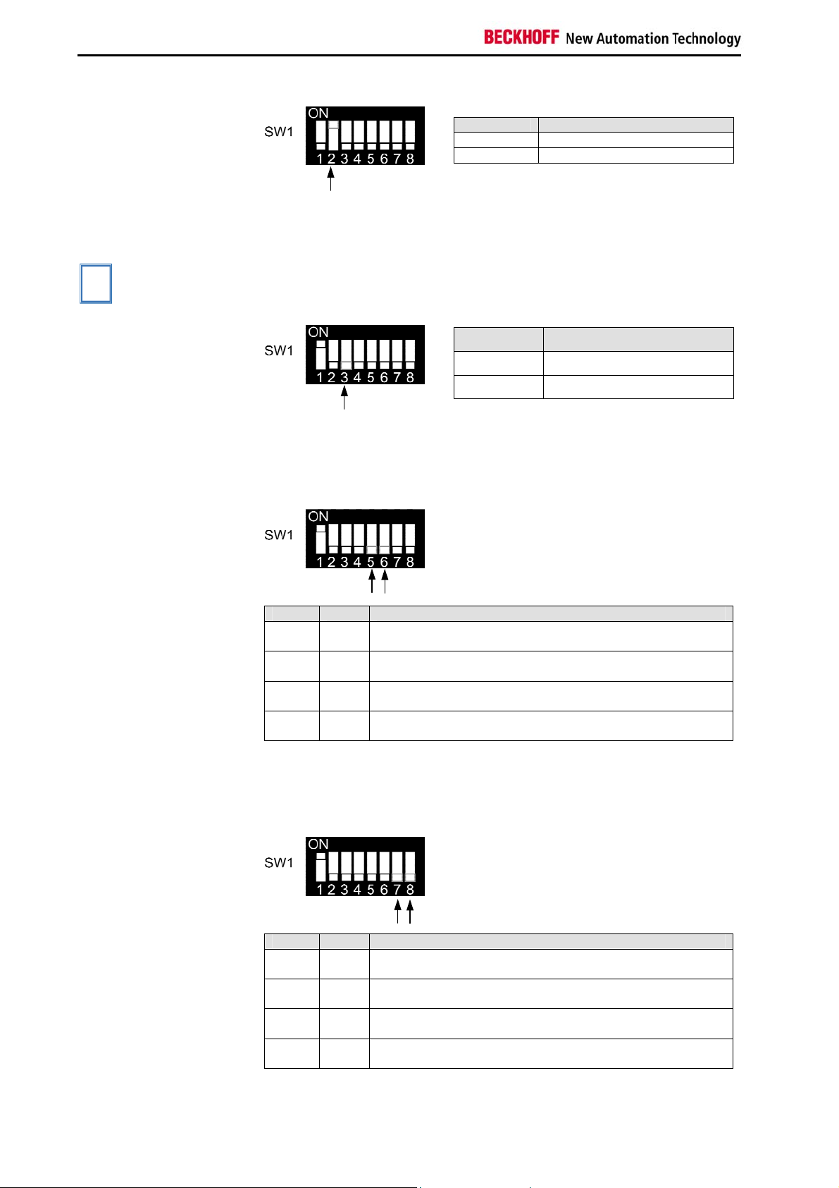
DIP Switch 1 (SW1)
This DIP switch configures the DVI input sources and the DDC signals.
Switch Name Function
1 PWRDVI 1 Activate DVI Input Port 0 (X40)
2 PWRDVI 2 Activate DVI Input Port 1 (X41)
3 OUT-LEVEL Set output level for DVI Output
4 N.C. Not used
5 A0_0 Address switch A0 for DVI Input Port 0 (X40)
6 A1_0 Address switch A1 for DVI Input Port 0 (X40)
7 A0_1 Address switch A0 for DVI Input Port 1 (X41)
8 A1_1 Address switch A1 for DVI Input Port 1 (X41)
The first two switches are used to enable/ disable the two DVI Input Ports:
PWRDVI 1
PWRDVI1 Function
on DVI Input Port 0 is activated
off DVI Input Port 0 is deactivated
CU8810-0000 9
Page 12
Operating Instructions
PWRDVI 2
PWRDVI2 Function
on DVI Input Port 1 is activated
off DVI Input Port 1 is deactivated
OUT-LEVEL
The next switch 3 is used to set the back termination for the output level.
The use of back terminations is highly recommended for best signal
integrity.
This switch is set to off by factory and should only be changed after
i
Note
consultation with the Beckhoff Support.
OUT-LEVEL Function
on No back termination is used
off Back termination is used
Switch 5 and 6
Switch 5 and 6 are paired to select the source for the DDC signal for
DVI Input Port 0. The DCC signal from the selected port is send to the
device connected to DVI Input Port 0.
Switch 7 and 8
The following table shows the possible selections.
5 6 Function
off off The DDC-channel from DVI Input Port 0 (X40) is connected to
DDC-channel to DVI Output Port 0 (X50)
on off The DDC-channel from DVI Input Port 0 (X40) is connected to
DDC-channel to DVI Output Port 1 (X51)
off on The DDC-channel from DVI Input Port 0 (X40) is connected to
DDC-channel to DVI Output Port 2 (X52)
on on The DDC-channel from DVI Input Port 0 (X40) is connected to
DDC-channel to DVI Output Port 3 (X53)
Switch 7 and 8 are paired to select the source for the DDC signal for
DVI Input Port 1. The DCC signal from the selected port is send to the
device connected to DVI Input Port 1.
The following table shows the possible selections.
7 8 Function
off off The DDC-channel from DVI Input Port 1 (X41) is connected to
DDC-channel to DVI Output Port 0 (X50)
on off The DDC-channel from DVI Input Port 1 (X41) is connected to
DDC-channel to DVI Output Port 1 (X51)
off on The DDC-channel from DVI Input Port 1 (X41) is connected to
DDC-channel to DVI Output Port 2 (X52)
on on The DDC-channel from DVI Input Port 1 (X41) is connected to
DDC-channel to DVI Output Port 3 (X53)
10 CU8810-0000
Page 13
Operating Instructions
i
Note
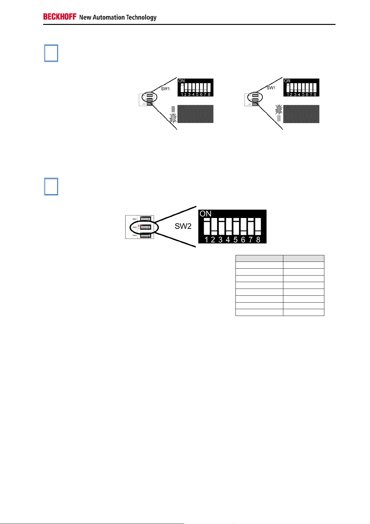
DIP Switch 2 (SW2)
i
Note
The DDC-channel of one DVI Output Port must not be mapped to both
DVI Input Ports. If there is no collision the green LED lights up. If there is a
collision the red LED lights up and the user has to change the DDCchannel settings.
o.k. collision
DIP Switch 2 (SW2)
This DIP switch block configures the signal parameters for
DVI Output Ports.
These switches are set as default from factory and should not be changed.
The default settings are:
Switch Setting
1 on
2 off
3 on
4 off
5 on
6 off
7 on
8 off
CU8810-0000 11
Page 14

Operating Instructions
p
DIP Switch 3 (SW3)
DIP Switch 3 (SW3)
This switch configures the output ports of the device. For each output port
there are two switches to select an input source.
Example
DVI Out
Switch Name Port Function
1 IN_SEL0_high 0
2 IN_SEL0_low 0
3 IN_SEL1_high 1
4 IN_SEL1_low 1
5 IN_SEL2_high 2
6 IN_SEL2_low 2
7 IN_SEL3_high 3
8 IN_SEL3_low 3
(X50)
(X50)
(X51)
(X51)
(X52)
(X52)
(X53)
(X53)
DVI Data Input Select Switch 1
for DVI Output Port 0 (X50)
DVI Data Input Select Switch 2
for DVI Output Port 0 (X50)
DVI Data Input Select Switch 1
for DVI Output Port 1 (X51)
DVI Data Input Select Switch 2
for DVI Output Port 1 (X51)
DVI Data Input Select Switch 1
for DVI Output Port 2 (X52)
DVI Data Input Select Switch 2
for DVI Output Port 2 (X52)
DVI Data Input Select Switch 1
for DVI Output Port 3 (X53)
DVI Data Input Select Switch 2
for DVI Output Port 3 (X53)
IN_SELx_high IN_SELx_low
off off Disable the DVI Output Port x
off on Select DVI Input Port 1 (X41) for
on off Select DVI Input Port 0 (X40) for
on on Illegal
Function
DVI Output Port x
DVI Output Port x
The displayed DIP Switch settings result
in the following functions:
Switch Setting
1 off
2 off
3 off
4 on
5 on
6 off
7 on
8 off
Function
Disable DVI Output Port 0 (X50)
Select DVI Input Port 1 (X41)
for DVI Output Port 1 (X51)
Select DVI Input Port 0 (X40)
for DVI Output Port 2 (X52)
Select DVI Input Port 0 (X40)
for DVI Output Port 3 (X53)
ut Port 0 1 2 3
12 CU8810-0000
Page 15

Operating Instructions
Architecture Description
Version 1
A PC with DVI output transfers an identical display image to up to four Control Panels. Command signals
can be transferred to the PC via USB from each Control Panel.
Version 2
If two PCs with one DVI output each are used, two different images can be transferred to the Control
Panels. The two images may have different screen resolutions.
Version 3
The two-PC principle also works using a PC with Core™ Duo technology. If two DVI outputs are used, two
different images can be transferred to the Control Panels. The two images may have different screen
resolutions. The two-channel C9900-A185 ADD2 card offers a simple option for installing an additional
DVI output. The card has two external DVI ports and enables direct connection of two DVI/USB Control
Panels to C5102, C6140, C6150, C6240 or C6250 PCs. Via the CU8810, these two DVI outputs can be
branched further to up to four Control Panels.
CU8810-0000 13
Page 16

Operating Instructions
Version 4
If a Panel PC with DVI output is used (e.g. “Economy” Panel PC CP62xx), the DVI splitter can be used to
transfer an image that differs from the main image on the Panel PC to up to four Control Panels. In this
case commands can also be transferred via USB from the individual Control Panels to the Panel PC.
14 CU8810-0000
Page 17
Appendix
Appendix
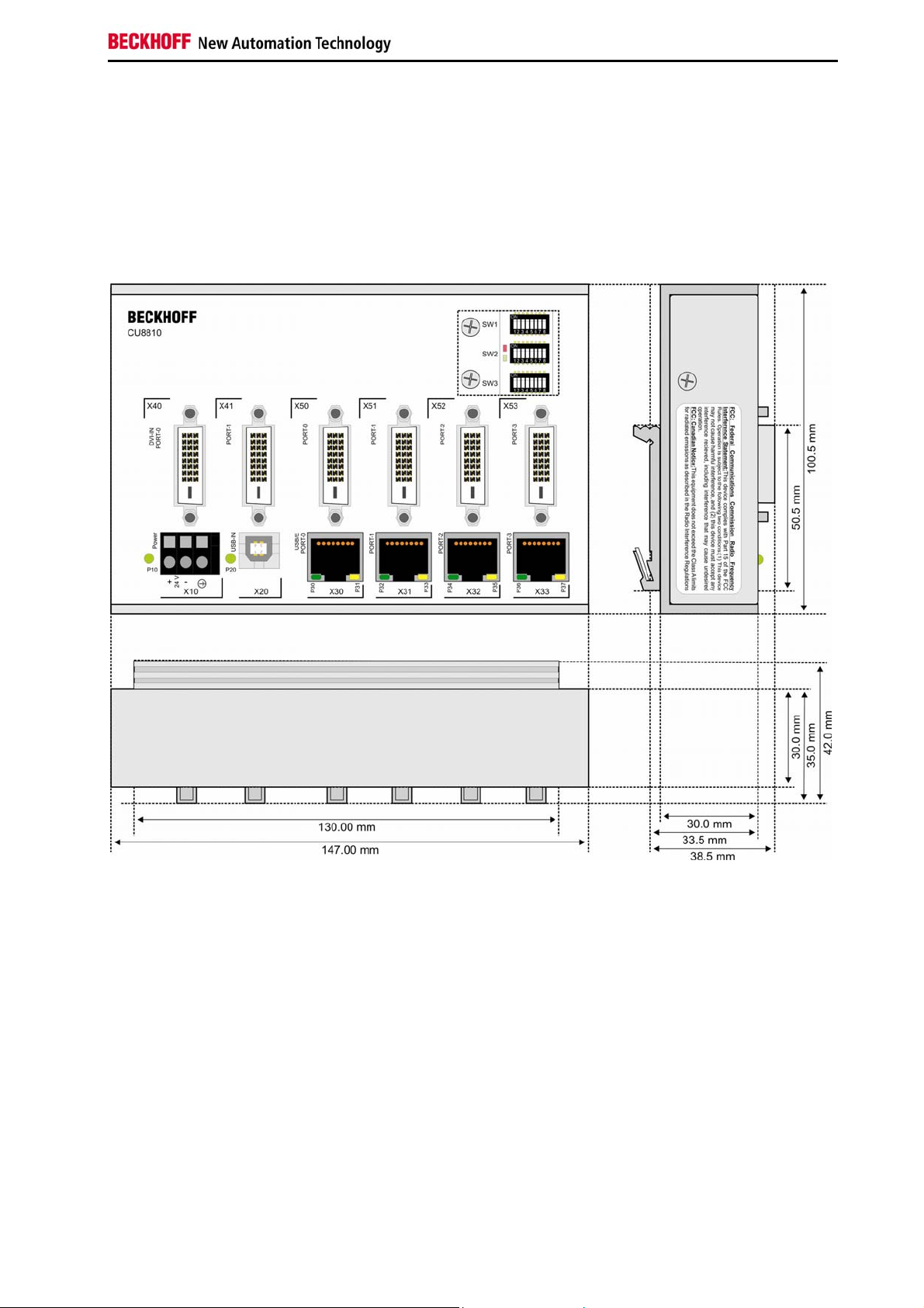
Assembly dimensions
The product is characterized by small overall installed size. With a height of
approx. 100 mm, the module dimensions exactly match those of the
Beckhoff Bus Terminals. Together with the lowered connector surfaces,
this means that it can be used in a standard terminal box with a height of
120 mm.
CU8810-0000 15
Page 18

Appendix
Beckhoff Support & Service
Quote the project number
Beckhoff and their partners around the world offer comprehensive support
and service, guaranteeing fast and competent assistance with all questions
related to Beckhoff products and system solutions.
Beckhoff branches and partner companies
Please contact your Beckhoff branch office or partner company for local
support and service on Beckhoff products!
The contact addresses for your country can be found in the list of Beckhoff
branches and partner companies: www.beckhoff.com
You will also find further documentation for Beckhoff components there.
Beckhoff Headquarters
Beckhoff Automation GmbH & Co. KG
Huelshorstweg 20
33415 Verl
Germany
Phone:
Fax: +49(0)5246/963-198
e-mail: info@beckhoff.com
+49(0)5246/963-0
Beckhoff Support
Beckhoff offers you comprehensive technical assistance, helping you not
only with the application of individual Beckhoff products, but also with wideranging services:
• worldwide support
• design, programming and commissioning of complex automation
systems
• training program for Beckhoff system components
Hotline:
Fax: +49(0)5246/963-9157
e-mail: support@beckhoff.com
+49(0)5246/963-157
Beckhoff Service
The Beckhoff service center supports you in all matters of after-sales
service:
• on-site service
• repair service
• spare parts service
• hotline service
Hotline:
Fax: +49(0)5246/963-479
e-mail: service@beckhoff.com
If servicing is required, please quote the project number of your product.
+49(0)5246/963-460
16 CU8810-0000
Page 19

Appendix
Technical data
Number of ports
Supported standard
Supported baud rates
Status display
USB extension wiring
USB Type B ports (downstream): 1
USB Extender Rx ports (RJ45): 4
DVI Input Ports: 2
DVI Output Ports: 4
USB 1.1
12 Mbit (Full Speed), 1.5 Mbit (Low Speed)
12 LEDs
Maximum 50 meters
length
USB wiring length
Power supply
Maximum 1 meters
24 V
(-15% to +20%), protected against polarity reversal.
DC
To meet the UL requirements use 4 A fuse or class 2 power supply!
Power consumption
Max. current input from 5 V
Maximum 2.7 W
Maximum 0 mA @ 5V
DC
USB
Current output over USB/E
Maximum 500 mA @ 15V
DC
The following conditions must be observed during operation:
Environmental conditions
Ambient temperature: 0 to 55°C (operation)
-25°C to +70°C (transport/ storage)
Atmospheric humidity: Maximum 95%, non-condensing
Vibration/ Shock resistance
EMC resistance burst/ ESD
Protection class
EN 60068-2-6 / EN 60068-2-27
EN 60000-6-2 / EN 60000-6-4
IP20
Do not use the CU8810 in
areas of explosive hazard
Dimensions (W x H x D)
Weight
Assembly
Installation position
Approvals
FCC Approval for USA
FCC Approval for Canada
The DVI splitter may not be used in areas of explosive hazard.
Approx. 146mm x 100mm x 42mm (with mounting for DIN rail)
Approx. 580 g
On 35 mm mounting rail conforms to EN 50022
Any
CE
Approvals for USA and Canada
FCC: Federal Communications Commission Radio Frequency Interference Statement
This equipment has been tested and found to comply with the limits for a Class A
digital device, pursuant to Part 15 of the FCC Rules. These limits are designed to
provide reasonable protection against harmful interference when the equipment is
operated in a commercial environment. This equipment generates, uses, and can
radiate radio frequency energy and, if not installed and used in accordance with the
instruction manual, may cause harmful interference to radio communications.
Operation of this equipment in a residential area is likely to cause harmful
interference in which case the user will be required to correct the interference at his
own expense.
FCC: Canadian Notice
This equipment does not exceed the Class A limits for radiated emissions as
described in the Radio Interference Regulations of the Canadian Department of
Communications.
CU8810-0000 17
 Loading...