

Page 1
Documentation for
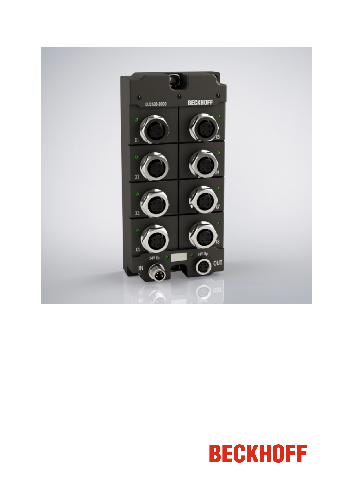
CU2608
8-Port Ethernet switch with IP67 protection class
Version: 1.0.0
Date: 2014-07-23
Page 2

Page 3

Table of contents
Table of contents
CU2608 - Ethernet Switch (IP67)
1. Foreword 1
Notes on the documentation 1
Safety instructions Fehler! Textmarke nicht definiert.
Documentation issue status 3
2. Product overview 4
Introduction 4
Baiscs of the functionality 5
Technical data 6
3. Mounting and cabling 7
Dimensions 7
Mounting 8
Nut torque for connectors 9
Ethernet cable 10
Power cables 12
Power cable conductor losses 13
Status LEDs 14
4. Appendix 16
General operating conditions 16
Accessories 17
Support and Service 18
CU2608
Page 4

Page 5

Foreword
1. Foreword
Notes on the documentation
This description is only intended for the use of trained specialists in control and automatio n engineering who are
familiar with the applicable national standards.
It is essential that the following notes and explanations are followed when installing an d commissioning these
components.
The responsible staff must ensure that the application or use of the products described satisfy all the requirements for
safety, including all the relevant laws, regulations, guidelines and standards.
Disclaimer
The documentation has been prepared with care. The products described are, however, constantly under
development.
For that reason the documentation is not in every case checked for consistency with performance data, standards or
other characteristics.
In the event that it contains technical or editorial errors, we retain the right to make alterations at any time and without
warning.
No claims for the modification of products that have already been supplied may be made on the basis of the data,
diagrams and descriptions in this documentation.
Trademarks
Beckhoff®, TwinCAT®, EtherCAT®, Safety over EtherCAT®, TwinSAFE®, XFC® and XTS® are registered trademarks
of and licensed by Beckhoff Automation GmbH.
Other designations used in this publication may be trademarks whose use by third parties for their own purposes
could violate the rights of the owners.
Patent Pending
The EtherCAT Technology is covered, including but not limited to the following patent applications and patents:
EP1590927, EP1789857, DE102004044764, DE102007017835
with corresponding applications or registrations in various other countries.
The TwinCAT Technology is covered, including but not limited to the following patent applications and patents:
EP0851348, US6167425 with corresponding applications or registratio ns in various other countries.
Copyright
© Beckhoff Automation GmbH, Germany.
The reproduction, distribution and utilization of this document as well as the communication of its contents to others
without express authorization are prohibited.
Offenders will be held liable for the payment of damages. All rights reserved in the event of the grant of a patent,
utility model or design.
CU2608 1
Page 6
Foreword
Safety instructions
Safety rules
Consider the following safety instructions and descriptions!
Product specific safety instructions are to be found on the following pages or in the areas mounting, wiring,
commissioning etc.
Disclaimer
All the components are supplied in particular hardware and software configurations appropriate for the application.
Modifications to hardware or software configurations other than those described in the documentation are not
permitted, and nullify the liability of Beckhoff Automation GmbH.
Personnel qualification
This description is only intended for the use of trained specialists in control, automation a nd drive engineering who
are familiar with the applicable national standards.
Description of symbols
The following symbols with a adjoining safety advise or notice are used in this documentation. You have to read the
safety advices carefully and adhere them strictly!
Acute risk of injury!
If you do not adhere the safety advise adjoining this symbol, there is immediate danger to
life and health of individuals!
DANGER
Risk of injury!
If you do not adhere the safety advise adjoining this symbol, there is danger to life and
health of individuals!
WARNING
Hazard to individuals!
If you do not adhere the safety advise adjoining this symbol, there is obvious hazard to
individuals!
CAUTION
Hazard to devices and environment
If you do not adhere the notice adjoining this symbol, there is obvious hazard to materials
and environment.
Attention
Note or pointer
This symbol indicates information that contributes to better understanding.
Note
2 CU2608
Page 7

Foreword
Documentation issue status
Version Comment
1.0.0 first release (technical data updated)
0.5.0 preliminary
CU2608 3
Page 8
Product overview
2. Product overview
Introduction
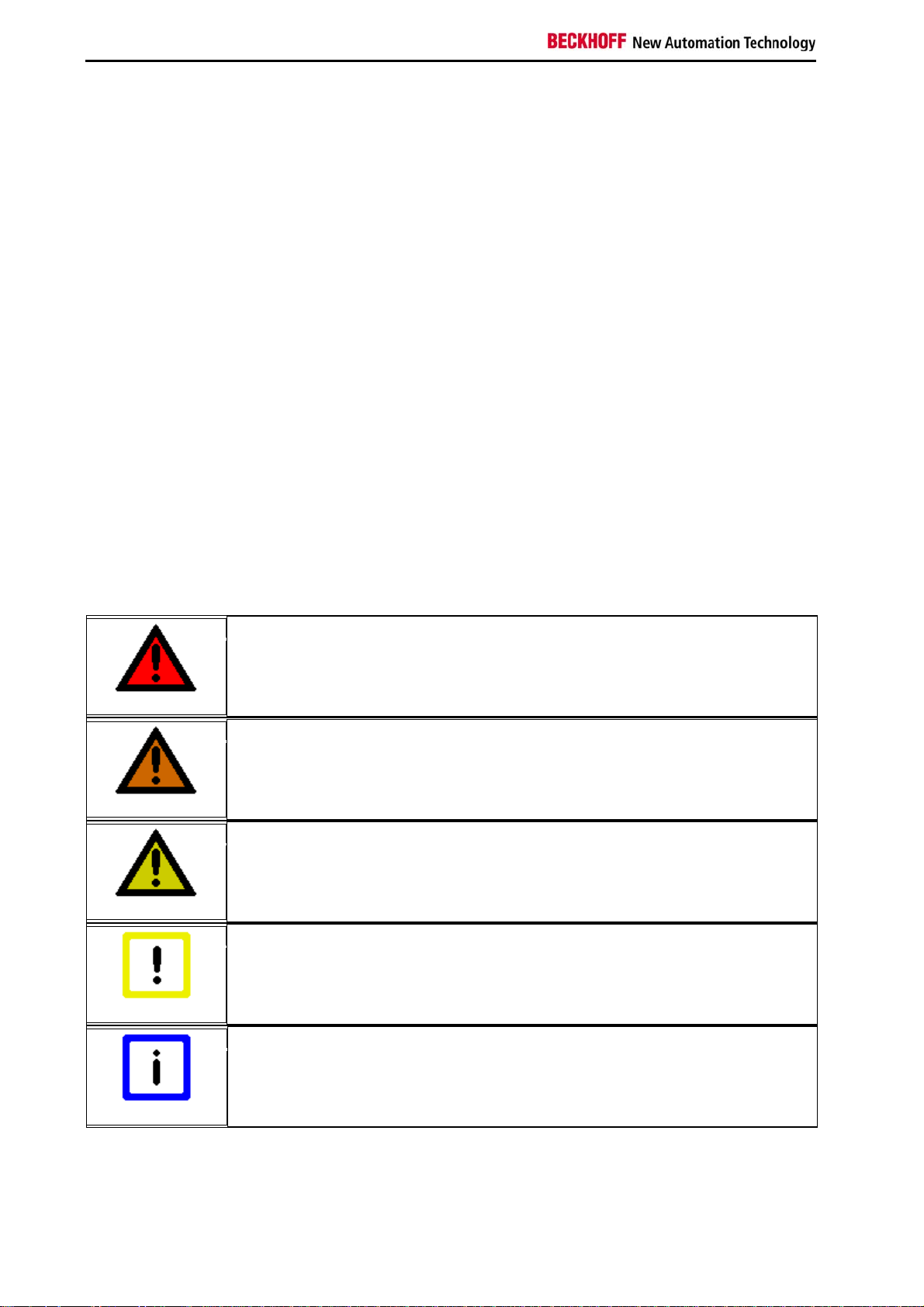
8-port Ethernet Switch with IP67 protection class
The CU2608 Ethernet Switch offers eight d-coded M12 Ethernet ports. Switches relay incoming Ethernet frames to
the destination ports. In full duplex mode, they prevent collisions.
They can be used universally in automation and office net works. Mounting can be carried out alternatively with two
central 4 mm screws or via two diagonal placed 3 mm screws.
The CU2608 meets the special requirements of real-time-capable Industrial Ethernet solutions through several
outstanding features:
• compact design in IP67 plastic housing
• eight d-coded M12 sockets
• 10/100 Mbaud, half or full duplex, with automatic baud rate detection
• cross-over detection: automatic detection and correction of crossover and straight-through Ethernet cables
• clear, quick diagnosis, 1 LED for each Ethernet port
• easy on-site installation
4 CU2608
Page 9

Product overview
Basic Function Principles
Store and Forward
The switch operates according to the store-and-forward principle. Frames that are faulty (CRC error), too short (< 64
bytes) or too long (> 1536 bytes) are not passed on in general.
Address Memory
The switch learns the MAC addresses of the connected devices for each port. Only frames that have these
addresses, broadcast/or multi-cast addresses, or which have unknown addresses are passed on to this port.
Because the switch remembers more than 1000 addresses for each port, it is also suitable for connecting entire
network segments. After approx. 5 minutes (Aging Time) unused addresses are removed from the memory – if
required, they are re-learnt again later.
Throughput
The switch can pass through up to 148800 Ethernet frames per second (Wire Speed).
PoE - Power over Ethernet
The switches CU20xx, CU22xx and CU26xx do not support the PoE acc. to IEEE 802.3, they do not indicate as a
PSE (power sourcing equipment) or PD (powered devices). Therefore, a PSE, which is connected to the switch, must
not put on voltage.
A passive transmitting or distribution is not intended in the standard
Jumbo Frames
Jumbo Frames are oversized Ethernet telegrams with a length of more than 1518 bytes. They are used in
applications that require very high data throughput, for example.
The CU2208 (from hardware version 01) supports Jumbo Frames up to 9720 bytes on all ports. Please note the
following:
• Jumbo Frames only supported by ports with Gbit link
• Jumbo Frames place high demands on internal data transmission. It is therefore necessary to assess the
data throughput that can be achieved through the CU2208 for each indiv idual application. Under full load no
more than 2 ports can be used for Jumbo Frames at the same time.
Jumbo Frames are not subject to standardization. It is therefore necessary to verify that the frames used by the
application are supported by the CU2208.
CU2608 5
Page 10

Product overview
Technical Data
Technical Data CU2608-0000
Bus system all Ethernet based protocols (IEEE 802.3)
Store-and-Forward switching mode, unmanaged
Number of Ethernet-Ports 8
Ethernet Interface 10BASE-T/100BASE-TX
Ethernet with M12, d-coded
Cable length up to 100 m CAT5, switches cascadable without restriction
Baud rate 10/100 Mbit/s, IEEE 802.3u auto-negotiation,
half or full duplex at 10 and 100 Mbit/s possible, automatic settings
Diagnosis 1 LED per channel: Link/Activity, LED for power supply
Power Supply feed and downstream connection via M8 connectors, 4-pin
Supply voltage 24 VDC (-15 %/+20 %)
Current consumption typically 120 mA
Weight app. 350 g
Dimensions without plugs (w x h x d) app. 126 x 60 x 26.5 mm
Mounting • Directly to mounting surface via two central 4 mm screws or via two
diagonal placed 3 mm screws.
• On Mounting Rail ZS5300-0001.
Permissible ambient temperature
range during operation
Permissible ambient temperature
range during storage
Vibration / shock resistance according to EN 60068-2-6 / EN 60068-2-27
EMC resistance burst / ESD according to EN 61000-6-2 / EN 61000-6-4
Protection class (according
toEN 60529)
Installation position variable
Approvals CE
-30°C ... + 70°C
-40°C ... + 85°C
IP65, IP66, IP67
6 CU2608
Page 11

Mounting and cabling
3. Mounting and cabling
Dimensions
All dimensions are given in millimeters.
Housing properties
EtherCAT Box lean body wide body
Housing material PA6 (polyamide)
Casting compound Polyurethane
Mounting two fastening holes Ø 3 mm for M3 two fastening holes Ø 3 mm for M3
two fastening holes Ø 4,5 mm for M4
Metal parts Brass, nickel-plated
Contacts CuZn, gold-plated
Power feed through max. 4 A
Installation position variable
Protection class IP65/66/67 (conforms to EN 60529) when screwed together
Dimensions (H x W x D) ca. 126 x 30 x 26,5 mm ca. 126 x 60 x 26,5 mm
Weight approx. 125 g, depending on module type approx. 250 g, depending on module type
Approvals CE, cULus CE
CU2608 7
Page 12
Mounting and cabling
Fixing
Note or pointer
While mounting the modules, protect all connectors, especially the IP-Link, against
contamination!
Note
Modules with narrow housing are mounted with two M3 bolts.
Modules with wide housing are mounted with two M3 bolts to the fixing holes locate d at the corners or mounted with
two M4 bolts to the fixing holes located centrally.
The bolts must be longer than 15 mm. The fixing holes of the modules are not threaded.
When assembling, remember that the fieldbus connectors increases the overall height. See chapter accessories.
Only with connected cables or plugs the protection class IP67 is guaranteed!
Unused connectors have to be protected with the right plugs! See for plug sets in the
catalogue.
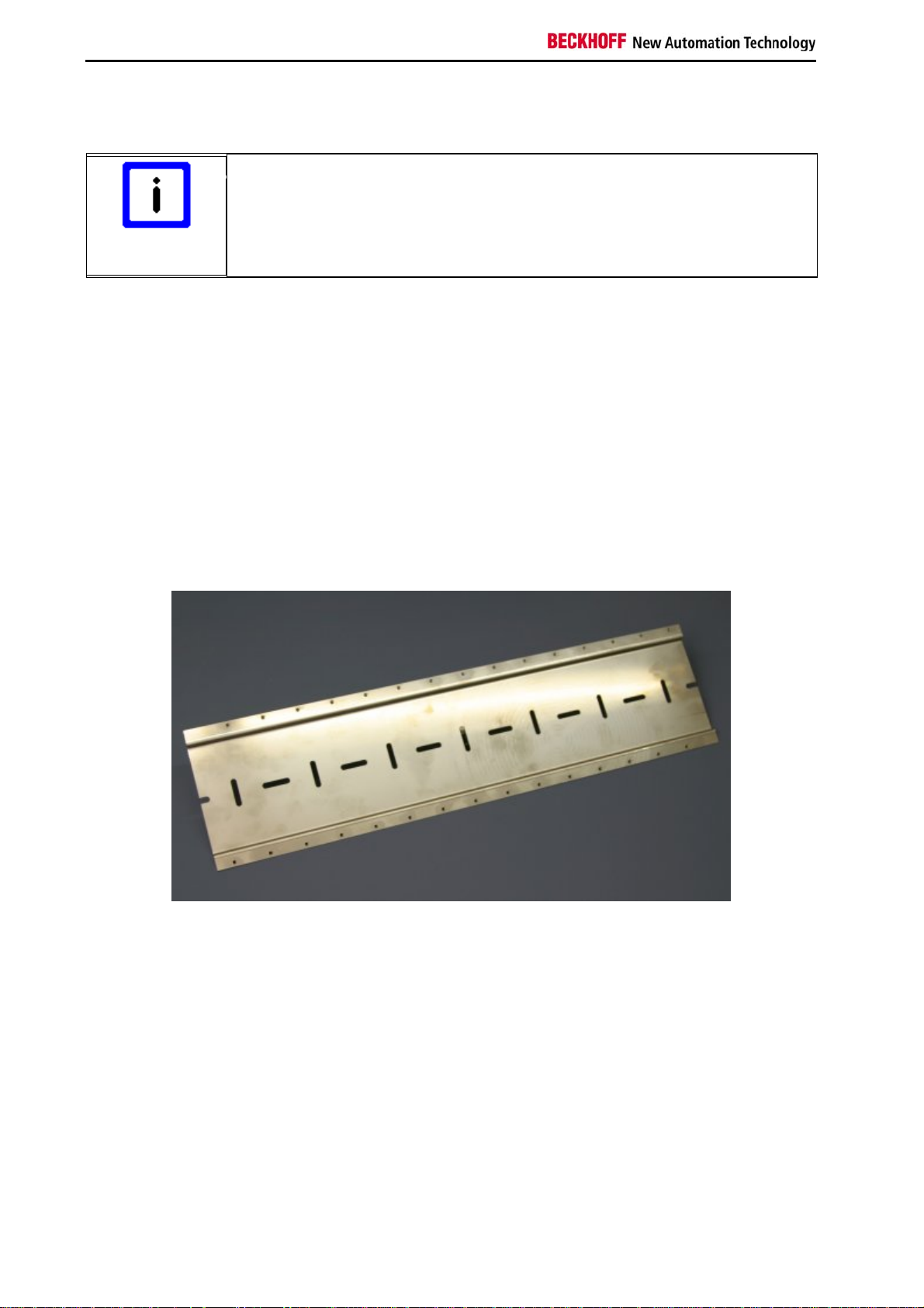
Mounting Rail ZS5300-0001
The mounting rail ZS5300-0001 (500 mm x 129 mm) allows the time saving assembly of modules.
The rail is made of stainless steel, 1.5 mm thick, with already pre-made M3 threads for the modules. The rail has got
5.3 mm slots to mount it via M5 screws to the machine.
The mounting rail is 500 mm long, that way 15 narrow modules can be mounted with a distance of 2 mm between
two modules. The rail can be cut to length for the application.
8 CU2608
Page 13
Mounting and cabling
Nut torque for connectors
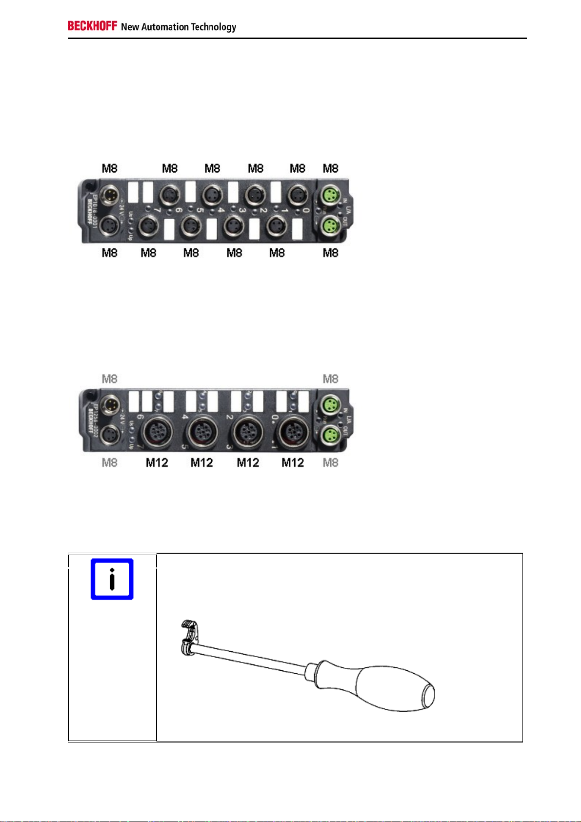
M8 connectors
It is recommended to pull the M8 connectors tight with a nut torque of 0.4 Nm.
M12 connectors
It is recommended to pull the M12 connectors tight with a nut torque of 0.6 Nm.
Torque socket wrenches
Ensure the right torque
Use the torque socket wrenches available by Beckhoff to pull the connectors tight (see
accessories)!
Note
CU2608 9
Page 14

Mounting and cabling
Ethernet cables
For connecting Ethernet devices only shielded Ethernet cables that meet the requirements of at least category 5
(CAt5) according to EN 50173 or ISO/IEC 11801 should be used.
Recommendations about cabling
You may get detailed recommendations about cabling Ethernet from the documentation
"Recommendations for the design of the infrastructure for EtherCAT/Ethernet", that is
available for download at www.Beckhoff.com.
Note
Ethernet uses 4 wires for signal transfer. Due to automatic cable detection (auto-crossing) symmetric (1:1) or crossover cables can be used between Ethernet devices from Beckhoff.
A selection of cables for Ethernet (her only up to 10m) follows. Other cables with various lengths will be found in the
full Beckhoff catalogue, and under www.beckhoff.com.
Sold by meter
Designation Description
ZB9010 CAT 5e, 4-core, for fixed laying, not for M8 connectors
ZB9020 CAT 5e, 4-core, suitable for drag chain use, not for M8 connectors
ZB9030 PVC, dia. 4.9 mm for M8 connectors
ZB9031 PUR, dia. 4.8 mm for M8 connectors
ZB9032 PUR, dia. 5.4 mm for M8 connectors, high flexibility
Pre assembled cables
ZK1090-6161-0xxx: M12 plug - M12 plug, PUR, ready-assembled
ZK1090-6161- 0005 0010 0020 0025 0050 0100
Length
0.5 m 1.0 m 2.0 m 2.5 m 5.0 m 10 m
10 CU2608
Page 15

Mounting and cabling
ZK1090-6191-0xxx: M12 plug - RJ45 plug, ready-assembled
ZK1090-6191- 0005 0010 0020 0025 0050 0100
Length
0.5 m 1.0 m 2.0 m 2.5 m 5.0 m 10 m
ZK1090-6292-0xxx: M12 socket - RJ45 plug, ready-assembled
ZK1090-6292- 0005 0020 0050 0100
Length
0.5 m 2 m 5 m 10 m
ZK1090-9191-0xxx: 2 x RJ45 plug, patch cable
ZK1090-9191- 0001 0002 0005 0010 0020 0030 0040 0050 0100 0150
Length
0.17 m 0.26 m 0.5 m 1.0 m 2.0 m 3.0 m 4.0 m 5.0 m 10 m 15 m
ZK1090-9191- 0200 0250 0300 0350 0400 0450 0500
Length
20 m 25 m 30 m 35 m 40 m 45 m 50 m
CU2608 11
Page 16

Mounting and cabling
Power cables
Ordering data
Screw-in
Order designation Power lead
ZK2020-3200-0020 2.00 m
ZK2020-3200-0050 5.00 m
ZK2020-3200-0100
ZK2020-3400-0020 2.00 m
ZK2020-3400-0050 5.00 m
ZK2020-3400-0100
ZK2020-3132-0001 0.15 m
ZK2020-3132-0005 0.50 m
ZK2020-3132-0010 1.00 m
ZK2020-3132-0020 2.00 m
ZK2020-3132-0050
ZK2020-3334-0001 0.15 m
ZK2020-3334-0005 0.50 m
ZK2020-3334-0010 1.00 m
ZK2020-3334-0020 2.00 m
ZK2020-3334-0050
Further available power cables may be found in the Beckhoff catalog or on our internet pages
(http://www.beckhoff.com).
Straight socket, open end
Angled socket, open end
Straight socket, straight socket
Angled socket, angled socket
connector Contacts
M8 4-pin 0.34 mm2
Crosssection Length
10.00 m
10.00 m
5.00 m
5.00 m
Technical data
Technical data
Rated voltage according to IEC60 664-1 60 VAC / 75 VDC
Contamination level according to IEC 60 664-1 3/2
Insulation resistance IEC 60 512-2 >109 Ω
Current carrying capacity according to IEC 60512-3 4 A
Volume resistance according to IEC 60512-2 < 5 mΩ
Protection class according to IEC 60529 IP65/66/67, when screwed together
Ambient temperature -30°C to +80°C
12 CU2608
Page 17

Mounting and cabling
Power cable conductor losses
The ZK2020-xxxx-yyyy power cables should not exceed the total length of 15 m at 4 A (with continuation). When
planning the cabling, note that at 24 V nominal voltage, the functionality of the module can no longer be assured if the
voltage drop reaches 6 V. Variations in the output voltage from the power supply unit must also be taken into
account.
Example
8 m power cable with 0.34 mm² cross-section has a voltage drop of 3.2 V at 4 A.
CU2608 13
Page 18

Mounting and cabling
LED Displays
Ethernet
For each of the eight channels 1 LEDs show the current status.
LED display per channel
LED Display
Link
Act
off no connection
on connection established (Link)
flashing data transmission active (Act)
14 CU2608
Page 19
Mounting and cabling
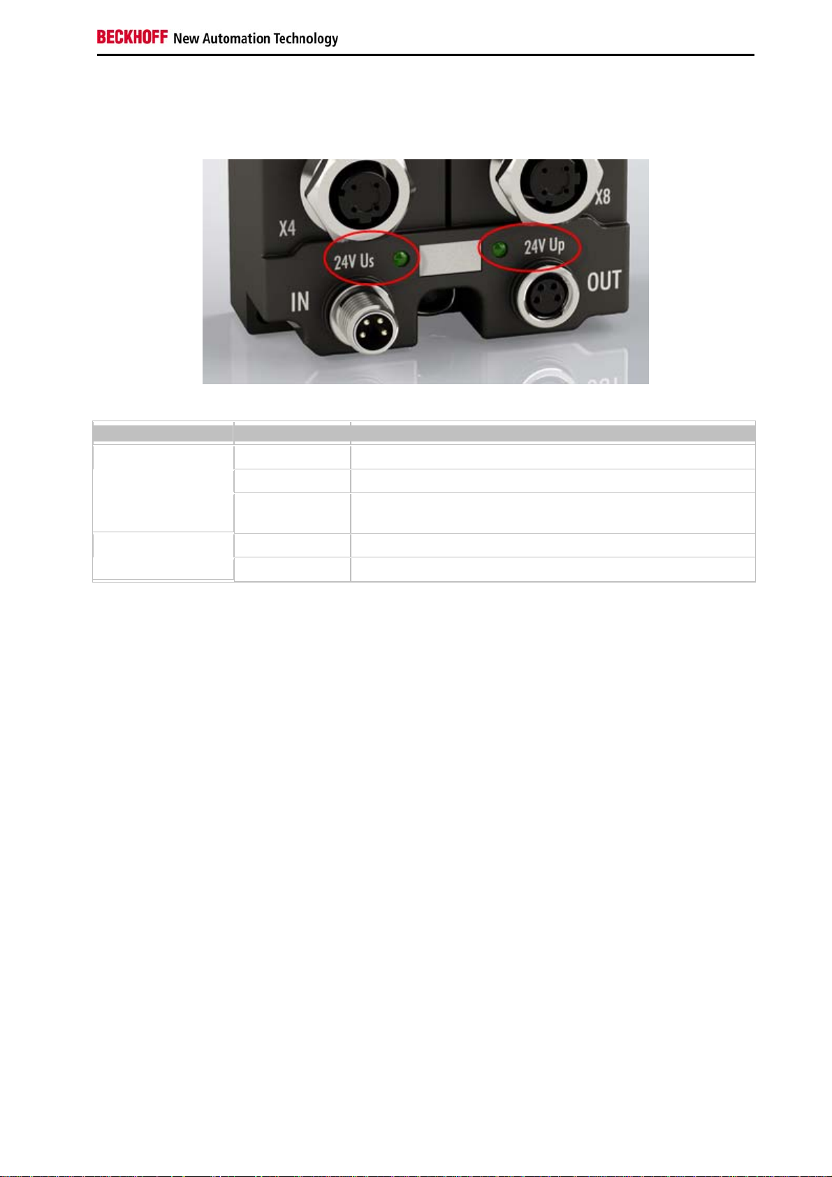
Power Supply
Present supply voltage (24 VDC) is shown by the green power LED.
LED Display Meaning
24V Us
(Control voltage)
(Auxiliary voltage)
The auxiliary voltage Up is not used within the CU2608 but it is fed trough.
off The power supply voltage Us is not present
green illuminated The power supply voltage Us is present
red illuminated Caused by overload (current > 0,5 A) the sensor supply generated
from supply voltage Us has been switched off for all sensors.
off The power supply voltage Up is not present 24V Up
green illuminated The power supply voltage Up is present
CU2608 15
Page 20

Appendix
4. Appendix
General operating conditions
Protection degrees (IP-Code)
The standard IEC 60529 (DIN EN 60529) defines the degrees of protection in different classes.
1. Number: dust
protection
and touch guard Definition
0
1 Protected against access to hazardous parts with the back of a hand. Protected against solid
2 Protected against access to hazardous parts with a finger. Protected against solid foreign
Non-protected
foreign objects of Ø50 mm
objects of Ø12,5 mm.
3 Protected against access to hazardous parts with a tool. Protected against solid foreign objects
Ø2,5 mm.
4 Protected against access to hazardous parts with a wire. Protected against solid foreign objects
Ø1 mm.
5 Protected against access to hazardous parts with a wire. Dust-protected. Intrusion of dust is not
totally prevented, but dust shall not penetrate in a quantity to interfere with satisfactory
operation of the device or to impair safety.
6 Protected against access to hazardous parts with a wire. Dust-tight. No intrusion of dust.
2. Number:
water* protection Definition
0
1 Protected against water drops
2 Protected against water drops when enclosure tilted up to 15°.
3 Protected against spraying water. Water sprayed at an angle up to 60° on either side of the
4 Protected against splashing water. Water splashed against the disclosure from an y direc tion
5
Non-protected
vertical shall have no harmful effects.
shall have no harmful effects
Protected against water jets
6 Protected against powerful water jets
7 Protected against the effects of temporary immersion in water. Intrusion of water in quantities
causing harmful effects shall not be possible when the enclosure is temporarily immersed in
water for 30 min. in 1 m depth.
*) These protection classes define only protection against water!
16 CU2608
Page 21

Appendix
Chemical Resistance
The Resistance relates to the Housing of the Fieldbus Box and the used metal parts.
Character Resistance
Steam at temperatures >100°C: not resistant
Sodium base liquor
(ph-Value > 12)
Acetic acid not resistant
Argon (technical clean) resistant
Key
resistant: Lifetime several months
non inherently resistant: Lifetime several weeks
not resistant: Lifetime several hours resp. early decomposition
at room temperature: resistant
> 40°C: not resistant
EtherCAT Box - Accessories
Fixing
Ordering information Description
ZS5300-0001 Mounting rail (500 mm x 129 mm)
Marking material, plugs
Ordering information Description
ZS5000-0000 Fieldbus Box set M8 (contact lab els, plugs)
ZS5000-0002 Fieldbus Box s et M12 (contact labels, plugs)
ZS5000-0010 plugs M8, IP67 (50 pieces)
ZS5000-0020 plugs M12, IP67 (50 pieces)
ZS5100-0000 marking labels, not printed, 4 stripes at 10 pieces
ZS5100-xxxx printed marking labels, on request
Tools
Ordering information Description
ZB8800 Torque socket wrench with ratchet wrench for M8 connectors (over molded)
ZB8800-0001 ratchet wrench for M8 connectors (field assembly)
ZB8800-0002 ratchet wrench for M12 conne c tors (over molded)
Further accessories
Further accessories may be found at the price list for Beckhoff fieldbus components and at
the internet under www.beckhoff.com.
Note
CU2608 17
Page 22

Appendix
Support and Service
Beckhoff and their partners around the world offer comprehensive support and service, making available fast and
competent assistance with all questions related to Beckhoff products and system solutions.
Beckhoff's branch offices and representatives
Please contact your Beckhoff branch office or representative for local support and service on Beckhoff products!
The addresses of Beckhoff's branch offices and representatives round the world can be found on her internet pages:
http://www.beckhoff.com
You will also find further documentation for Beckhoff components there.
Beckhoff Headquarters
Beckhoff Automation GmbH
Eiserstr. 5
33415 Verl
Germany
Phone: +49(0)5246/963-0
Fax: +49(0)5246/963-198
e-mail: info@beckhoff.com
Beckhoff Support
Support offers you comprehensive technical assistance, helping you not only with the application of individual
Beckhoff products, but also with other, wide-ranging services:
• support
• design, programming and commissioning of complex automation systems
• and extensive training program for Beckhoff system components
Hotline: +49(0)5246/963-157
Fax: +49(0)5246/963-9157
e-mail: support@beckhoff.com
Beckhoff Service
The Beckhoff Service Center supports you in all matters of after-sales service:
• on-site service
• repair service
• spare parts service
• hotline service
Hotline: +49(0)5246/963-460
Fax: +49(0)5246/963-479
e-mail: service@beckhoff.com
18 CU2608
 Loading...