

Page 1

Documentation | EN
CU1521-xxxx, CU1561
EtherCAT media converter (RJ45, LWL, POF)
2020-11-06 | Version: 2.4
Page 2

Page 3

Table of contents
Table of contents
1 Foreword ....................................................................................................................................................5
1.1 CU15x1 - Product overview...............................................................................................................5
1.2 Notes on the documentation..............................................................................................................5
1.3 Safety instructions .............................................................................................................................7
1.4 Documentation issue status ..............................................................................................................8
1.5 Version identification of EtherCAT devices .......................................................................................8
1.5.1 Beckhoff Identification Code (BIC)................................................................................... 13
2 Product overview.....................................................................................................................................15
2.1 Introduction......................................................................................................................................15
2.2 Technical data .................................................................................................................................17
3 Basic principles .......................................................................................................................................18
3.1 EtherCAT basics..............................................................................................................................18
3.2 EtherCAT cabling – wire-bound.......................................................................................................18
3.3 EtherCAT State Machine.................................................................................................................19
3.4 CoE - Interface: notes......................................................................................................................20
4 Mounting and wiring................................................................................................................................21
4.1 Dimensions......................................................................................................................................21
4.2 Mounting and demounting ...............................................................................................................22
4.3 Recommended mounting rails.........................................................................................................23
4.4 Diagnostic LEDs ..............................................................................................................................24
4.5 UL notice .........................................................................................................................................25
5 Commissioning/application notes .........................................................................................................26
5.1 Application notes .............................................................................................................................26
5.2 Notes on converters with RJ45 fiber-optic connection ....................................................................30
5.2.1 Principles of fiber-optic technology .................................................................................. 30
5.2.2 Notes on suitable optical fiber cables .............................................................................. 35
5.2.3 Application with CU1521 and CU1521-0010 ................................................................... 36
5.2.4 Connecting and disconnecting the fiber cable ................................................................. 37
5.3 Notes on converters with RJ45 POF connection.............................................................................38
5.3.1 Notes regarding suitable POF cables .............................................................................. 38
5.3.2 Connecting and disconnecting the POF cable................................................................. 39
5.4 Notes regarding assembly of POF cables with the connector set ZS1090-0008 ............................40
6 Appendix ..................................................................................................................................................45
6.1 Safety instructions and behavioral rules for Class 1 laser...............................................................45
6.2 Firmware compatibility.....................................................................................................................45
6.3 Firmware Update EL/ES/EM/ELM/EPxxxx ......................................................................................45
6.3.1 Device description ESI file/XML....................................................................................... 46
6.3.2 Firmware explanation ...................................................................................................... 49
6.3.3 Updating controller firmware *.efw................................................................................... 50
6.3.4 FPGA firmware *.rbf......................................................................................................... 52
6.3.5 Simultaneous updating of several EtherCAT devices...................................................... 56
6.4 Support and Service ........................................................................................................................57
CU1521-xxxx, CU1561 3Version: 2.4
Page 4

Table of contents
CU1521-xxxx, CU15614 Version: 2.4
Page 5

Foreword
1 Foreword
1.1 CU15x1 - Product overview
CU1521 [}15] - EtherCAT media converter multimode fiber optic
CU1521-0010 [}15] - EtherCAT media converter singlemode fiber optic
CU1561 [}15] - EtherCAT media converter fiber optic (POF)
1.2 Notes on the documentation
Intended audience
This description is only intended for the use of trained specialists in control and automation engineering who
are familiar with the applicable national standards.
It is essential that the documentation and the following notes and explanations are followed when installing
and commissioning these components.
It is the duty of the technical personnel to use the documentation published at the respective time of each
installation and commissioning.
The responsible staff must ensure that the application or use of the products described satisfy all the
requirements for safety, including all the relevant laws, regulations, guidelines and standards.
Disclaimer
The documentation has been prepared with care. The products described are, however, constantly under
development.
We reserve the right to revise and change the documentation at any time and without prior announcement.
No claims for the modification of products that have already been supplied may be made on the basis of the
data, diagrams and descriptions in this documentation.
Trademarks
Beckhoff®, TwinCAT®, EtherCAT®, EtherCATG®, EtherCATG10®, EtherCATP®, SafetyoverEtherCAT®,
TwinSAFE®, XFC®, XTS® and XPlanar® are registered trademarks of and licensed by Beckhoff Automation
GmbH. Other designations used in this publication may be trademarks whose use by third parties for their
own purposes could violate the rights of the owners.
Patent Pending
The EtherCAT Technology is covered, including but not limited to the following patent applications and
patents: EP1590927, EP1789857, EP1456722, EP2137893, DE102015105702 with corresponding
applications or registrations in various other countries.
EtherCAT® is registered trademark and patented technology, licensed by Beckhoff Automation GmbH,
Germany.
CU1521-xxxx, CU1561 5Version: 2.4
Page 6

Foreword
Copyright
© Beckhoff Automation GmbH & Co. KG, Germany.
The reproduction, distribution and utilization of this document as well as the communication of its contents to
others without express authorization are prohibited.
Offenders will be held liable for the payment of damages. All rights reserved in the event of the grant of a
patent, utility model or design.
CU1521-xxxx, CU15616 Version: 2.4
Page 7
Foreword
1.3 Safety instructions
Safety regulations
Please note the following safety instructions and explanations!
Product-specific safety instructions can be found on following pages or in the areas mounting, wiring,
commissioning etc.
Exclusion of liability
All the components are supplied in particular hardware and software configurations appropriate for the
application. Modifications to hardware or software configurations other than those described in the
documentation are not permitted, and nullify the liability of Beckhoff Automation GmbH & Co. KG.
Personnel qualification
This description is only intended for trained specialists in control, automation and drive engineering who are
familiar with the applicable national standards.
Description of instructions
In this documentation the following instructions are used.
These instructions must be read carefully and followed without fail!
DANGER
Serious risk of injury!
Failure to follow this safety instruction directly endangers the life and health of persons.
WARNING
Risk of injury!
Failure to follow this safety instruction endangers the life and health of persons.
CAUTION
Personal injuries!
Failure to follow this safety instruction can lead to injuries to persons.
NOTE
Damage to environment/equipment or data loss
Failure to follow this instruction can lead to environmental damage, equipment damage or data loss.
Tip or pointer
This symbol indicates information that contributes to better understanding.
CU1521-xxxx, CU1561 7Version: 2.4
Page 8

Foreword
1.4 Documentation issue status
Version Modifications
2.4 • Update chapter “Notes on converters with RJ45 fiber-optic connection”
• Update structure
2.3 • Update chapter “Commissioning”
• Update Technical Data
• Update structure
2.2 • Update Technical Data
• Update structure
2.1 • Update Technical Data
• Update structure
2.0 • Migration
1.2 • Update chapter "Technical data"
1.1 • Update chapter "Application notes"
1.0 • Addenda and 1st public issue
0.3 • Addenda
0.2 • Addenda
0.1 • Preliminary version
1.5 Version identification of EtherCAT devices
Designation
A Beckhoff EtherCAT device has a 14-digit designation, made up of
• family key
• type
• version
• revision
Example Family Type Version Revision
EL3314-0000-0016 EL terminal
(12 mm, nonpluggable connection
level)
ES3602-0010-0017 ES terminal
(12 mm, pluggable
connection level)
CU2008-0000-0000 CU device 2008 (8-port fast ethernet switch) 0000 (basic type) 0000
Notes
• The elements mentioned above result in the technical designation. EL3314-0000-0016 is used in the
example below.
• EL3314-0000 is the order identifier, in the case of “-0000” usually abbreviated to EL3314. “-0016” is the
EtherCAT revision.
• The order identifier is made up of
- family key (EL, EP, CU, ES, KL, CX, etc.)
- type (3314)
- version (-0000)
3314 (4-channel thermocouple
terminal)
3602 (2-channel voltage
measurement)
0000 (basic type) 0016
0010 (highprecision version)
0017
CU1521-xxxx, CU15618 Version: 2.4
Page 9

Foreword
• The revision -0016 shows the technical progress, such as the extension of features with regard to the
EtherCAT communication, and is managed by Beckhoff.
In principle, a device with a higher revision can replace a device with a lower revision, unless specified
otherwise, e.g. in the documentation.
Associated and synonymous with each revision there is usually a description (ESI, EtherCAT Slave
Information) in the form of an XML file, which is available for download from the Beckhoff web site.
From 2014/01 the revision is shown on the outside of the IP20 terminals, see Fig. “EL5021 EL terminal,
standard IP20 IO device with batch number and revision ID (since 2014/01)”.
• The type, version and revision are read as decimal numbers, even if they are technically saved in
hexadecimal.
Identification number
Beckhoff EtherCAT devices from the different lines have different kinds of identification numbers:
Production lot/batch number/serial number/date code/D number
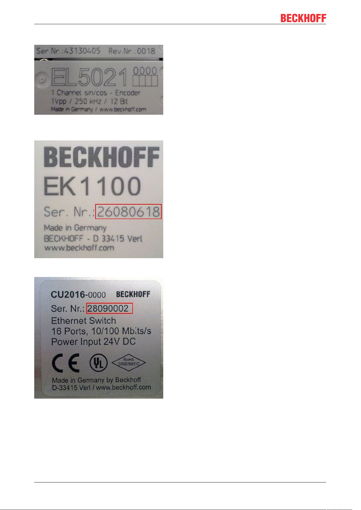
The serial number for Beckhoff IO devices is usually the 8-digit number printed on the device or on a sticker.
The serial number indicates the configuration in delivery state and therefore refers to a whole production
batch, without distinguishing the individual modules of a batch.
Structure of the serial number: KKYYFFHH
KK - week of production (CW, calendar week)
YY - year of production
FF - firmware version
HH - hardware version
Example with
Ser. no.: 12063A02: 12 - production week 12 06 - production year 2006 3A - firmware version 3A 02 hardware version 02
Exceptions can occur in the IP67 area, where the following syntax can be used (see respective device
documentation):
Syntax: D ww yy x y z u
D - prefix designation
ww - calendar week
yy - year
x - firmware version of the bus PCB
y - hardware version of the bus PCB
z - firmware version of the I/O PCB
u - hardware version of the I/O PCB
Example: D.22081501 calendar week 22 of the year 2008 firmware version of bus PCB: 1 hardware version
of bus PCB: 5 firmware version of I/O PCB: 0 (no firmware necessary for this PCB) hardware version of I/O
PCB: 1
Unique serial number/ID, ID number
In addition, in some series each individual module has its own unique serial number.
See also the further documentation in the area
• IP67: EtherCAT Box
• Safety: TwinSafe
• Terminals with factory calibration certificate and other measuring terminals
CU1521-xxxx, CU1561 9Version: 2.4
Page 10
Foreword
Examples of markings
Fig.1: EL5021 EL terminal, standard IP20 IO device with serial/ batch number and revision ID (since
2014/01)
Fig.2: EK1100 EtherCAT coupler, standard IP20 IO device with serial/ batch number
Fig.3: CU2016 switch with serial/ batch number
CU1521-xxxx, CU156110 Version: 2.4
Page 11
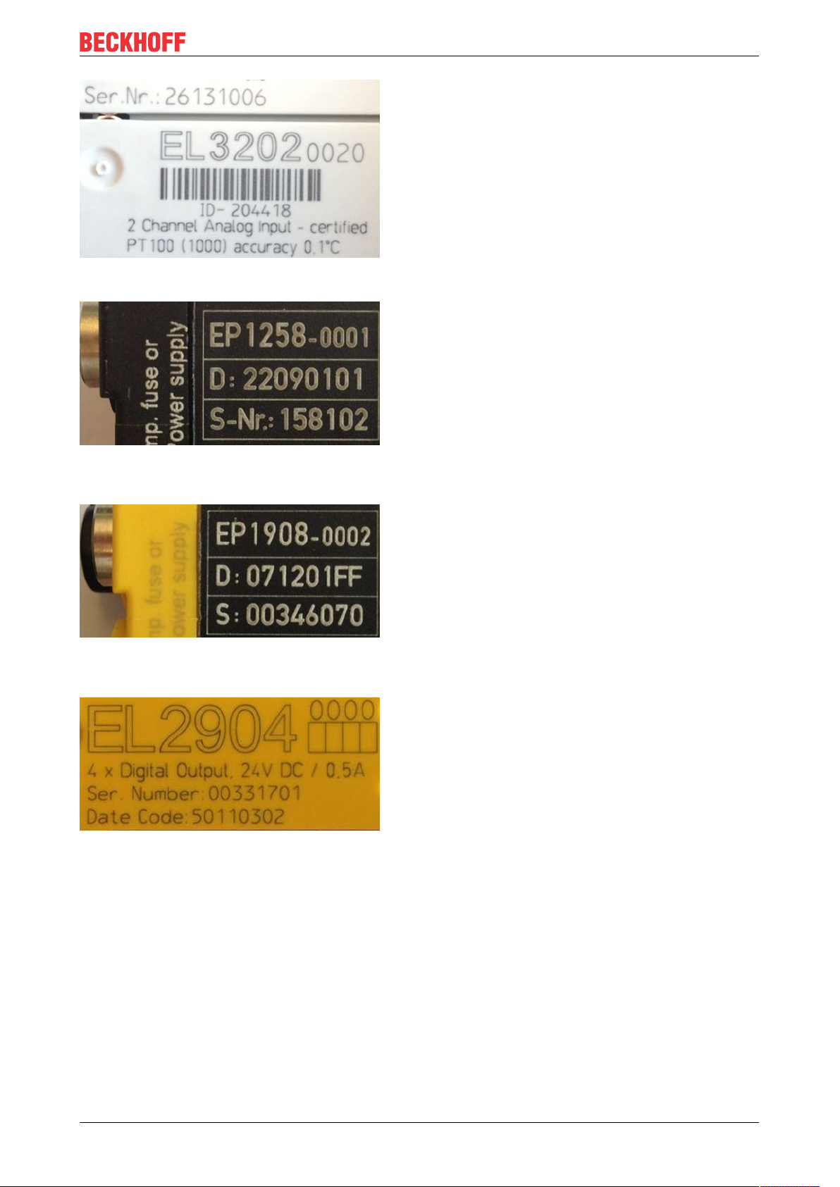
Fig.4: EL3202-0020 with serial/ batch number 26131006 and unique ID-number 204418
Foreword
Fig.5: EP1258-00001 IP67 EtherCAT Box with batch number/ date code 22090101 and unique serial
number 158102
Fig.6: EP1908-0002 IP67 EtherCAT Safety Box with batch number/ date code 071201FF and unique serial
number 00346070
Fig.7: EL2904 IP20 safety terminal with batch number/ date code 50110302 and unique serial number
00331701
CU1521-xxxx, CU1561 11Version: 2.4
Page 12

Foreword
Fig.8: ELM3604-0002 terminal with unique ID number (QR code) 100001051 and serial/ batch number
44160201
CU1521-xxxx, CU156112 Version: 2.4
Page 13
Foreword
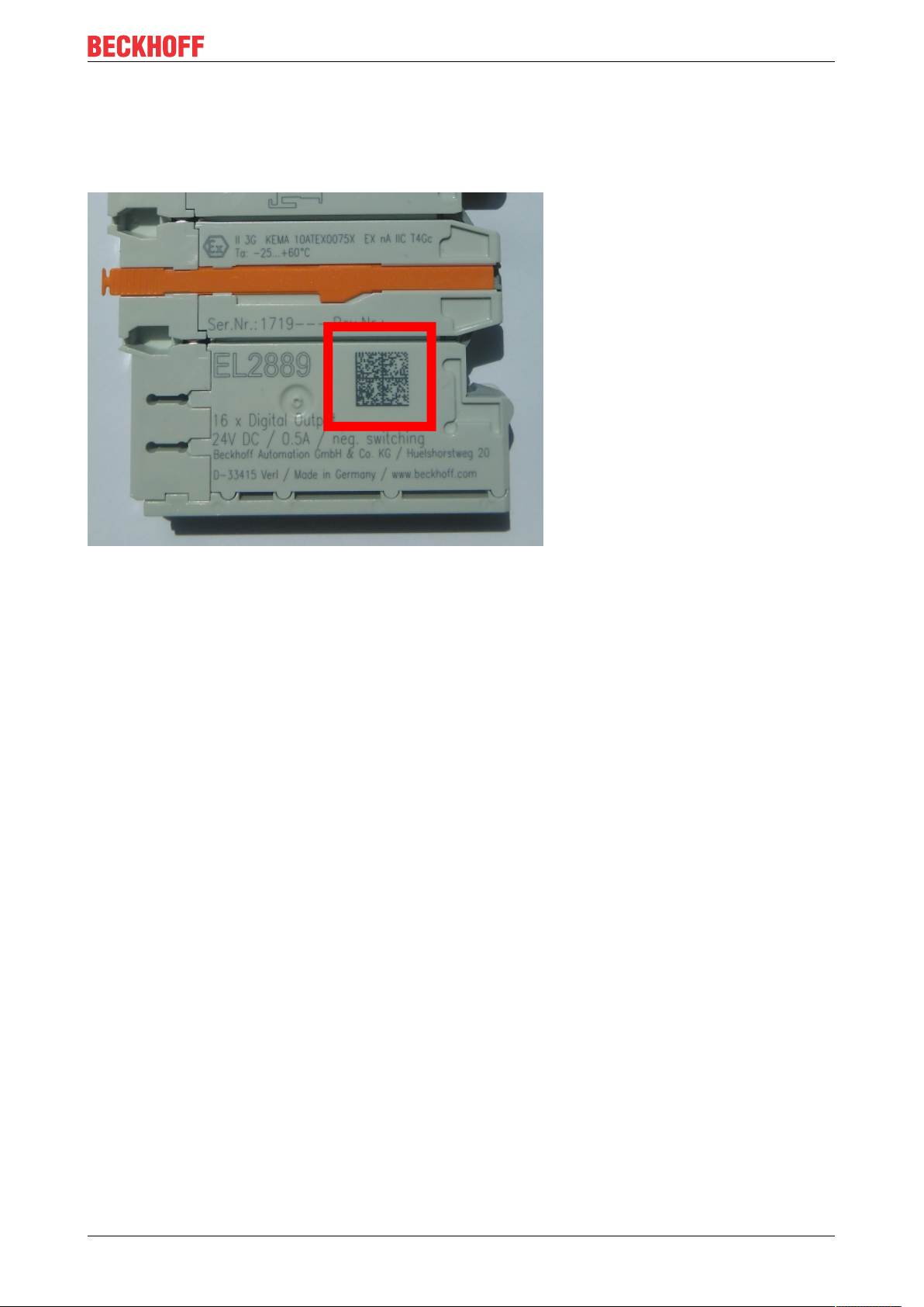
1.5.1 Beckhoff Identification Code (BIC)
The Beckhoff Identification Code (BIC) is increasingly being applied to Beckhoff products to uniquely identify
the product. The BIC is represented as a Data Matrix Code (DMC, code scheme ECC200), the content is
based on the ANSI standard MH10.8.2-2016.
Fig.9: BIC as data matrix code (DMC, code scheme ECC200)
The BIC will be introduced step by step across all product groups.
Depending on the product, it can be found in the following places:
• on the packaging unit
• directly on the product (if space suffices)
• on the packaging unit and the product
The BIC is machine-readable and contains information that can also be used by the customer for handling
and product management.
Each piece of information can be uniquely identified using the so-called data identifier
(ANSIMH10.8.2-2016). The data identifier is followed by a character string. Both together have a maximum
length according to the table below. If the information is shorter, spaces are added to it. The data under
positions 1 to 4 are always available.
The following information is contained:
CU1521-xxxx, CU1561 13Version: 2.4
Page 14

Foreword
Item
Type of
no.
information
1 Beckhoff order
number
2 Beckhoff Traceability
Number (BTN)
3 Article description Beckhoff article
4 Quantity Quantity in packaging
5 Batch number Optional: Year and week
6 ID/serial number Optional: Present-day
7 Variant number Optional: Product variant
...
Explanation Data
Beckhoff order number 1P 8 1P072222
Unique serial number,
see note below
description, e.g.
EL1008
unit, e.g. 1, 10, etc.
of production
serial number system,
e.g. with safety products
number on the basis of
standard products
Number of digits
identifier
S 12 SBTNk4p562d7
1K 32 1KEL1809
Q 6 Q1
2P 14 2P401503180016
51S 12 51S678294104
30P 32 30PF971, 2*K183
incl. data identifier
Example
Further types of information and data identifiers are used by Beckhoff and serve internal processes.
Structure of the BIC
Example of composite information from item 1 to 4 and 6. The data identifiers are marked in red for better
display:
BTN
An important component of the BIC is the Beckhoff Traceability Number (BTN, item no.2). The BTN is a
unique serial number consisting of eight characters that will replace all other serial number systems at
Beckhoff in the long term (e.g. batch designations on IO components, previous serial number range for
safety products, etc.). The BTN will also be introduced step by step, so it may happen that the BTN is not yet
coded in the BIC.
NOTE
This information has been carefully prepared. However, the procedure described is constantly being further
developed. We reserve the right to revise and change procedures and documentation at any time and without prior notice. No claims for changes can be made from the information, illustrations and descriptions in
this information.
CU1521-xxxx, CU156114 Version: 2.4
Page 15
2 Product overview
2.1 Introduction
Product overview
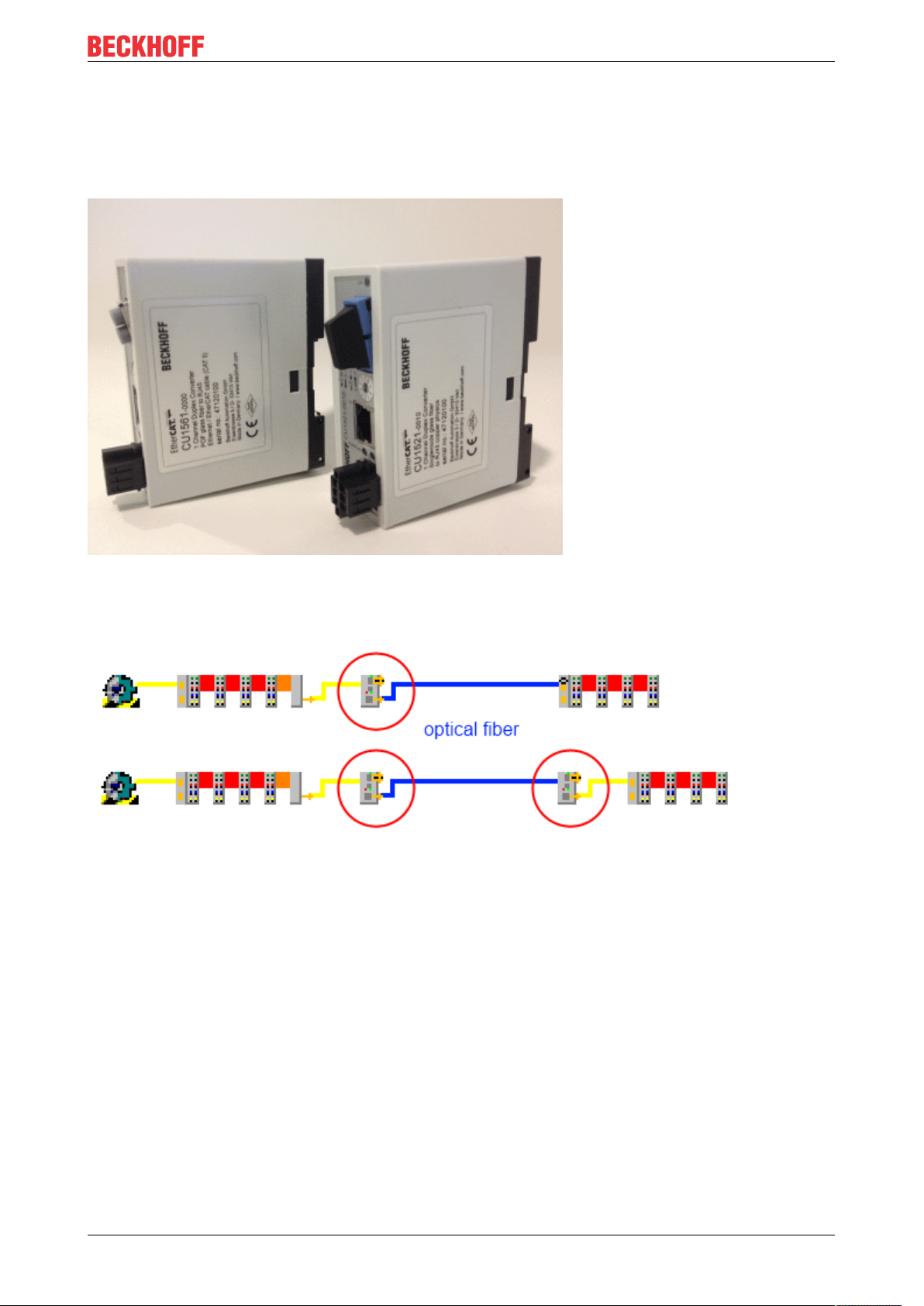
Fig.10: CU1561, CU1521
The EtherCAT-capable CU1521, CU1521-0010 and CU1561 devices should be used as media converter for
industrial fast Ethernet/100 Mbaud from optical fiber to copper and vice versa.
Fig.11: Upper picture: one media converter, copper -> fiber optic,
Lower picture: two media converters, copper -> fiber optic -> copper
From the physical layer perspective the CU1521 is suitable for multimode, while the CU1521-0010 is suitable
for single mode optical fiber and therefore for significantly longer transmission links up to 20 km.
The CU1561 is used for interfacing with POF (plastic optical fiber), which are suitable for small-scale
machine installation thanks to relatively inexpensive cable material and field-configurability.
The media converter operates bidirectionally and collision-free. The CU15x1 devices are therefore also
suitable as media converters for any Ethernet traffic. They support "Link Loss Forwarding", which means
that, if the link fails at the outgoing strand, for example due to a broken wire, the link is also withdrawn from
the incoming line, so that the sending device is notified of the link loss.
The CU15x1 devices are characterized by the fact that they support the requirements of an EtherCAT
network for a converter particularly well. This includes fast link control (establishment and disconnection),
diagnosis of communication errors, constant frame deceleration and readable identity (no transparent
operation). If the CU15x1 is set to EtherCAT mode with the rotary switch, it can be diagnosed as a separate
EtherCAT device. Hence, as opposed to standard media converters, he also ensures fast link control and
thus the secure termination of an EtherCAT strand even in the event of a disruption. Since the transfer
direction (copper Þ optical fiber or optical fibers Þ copper) is relevant for the EtherCAT bus, the operating
direction can be configured via the rotary switch.
CU1521-xxxx, CU1561 15Version: 2.4
Page 16

Product overview
The CU15x1 are useful in applications where EtherCAT transfers over large distances are required or where
higher EMC loads on the bus line are to be expected.
Quick links
• EtherCAT basics
• Application notes [}26]
• Diagnostic LEDs [}24]
CU1521-xxxx, CU156116 Version: 2.4
Page 17

Product overview
2.2 Technical data
Technical data CU1521 CU1521-0010 CU1561
Function Ethernet "IP" Media converter Fast Ethernet/100Mbaud (all IEEE 802.3-based
protocols)
IEEE 802.3u auto negotiation, half or full duplex, automatic settings
Link Loss-Forwarding (notification direction configurable)
Store and Forward Mode (FIFO)
unmanaged
Function EtherCAT "EC" Media converter Fast Ethernet/100Mbaud
Cut-through mode
Port handling/link control
Number of Ethernet ports 2
Ethernet interface X1 100BASE-FX
multimode glass fiber
50/125µm (MM)
typically 1300nm
1 x SC Duplex
100BASE-FX single
mode glass fiber
9/125µm (SM)
typically 1300nm
1 x SC Duplex
100BASE-FX-POF
glass fiber 980/1000
µm (POF);
typically 650nm
1 x versatile link for
POF duplex connector
(connector set
ZS1090-0008)
Laser class 1, see note
[}45]
Ethernet interface X2 10BASE-T/100BASE-TX Ethernet/EtherCAT cable (min. CAT 5),
screened
RJ45
Cable length X1 max. max. 2km (100BASE-
FX)
Cable length X2 max. up to 100m twisted pair CAT5 (e)
Diagnostics LED: Supply voltage, link/activity X1/X2
EtherCAT: CRC
Power supply via three-pole spring loaded terminal (+, -, PE)
Supply voltage 24VDC (18VDC to 30VDC), protected against polarity reversal.
Current consumption typ. 95mA typ. 80mA typ. 60mA
Weight approx. 105g
Dimensions without plugs (W x H
x D)
Mounting [}22]
Permissible ambient temperature
range during operation
Permissible ambient temperature
range during storage
Permissible relative humidity 95%, no condensation
Vibration/shock resistance conforms to EN60068-2-6/ EN60068-2-27, EN60068-2-29
EMC immunity/emission conforms to EN 61000-6-2 / EN 61000-6-4
Protection class IP20
Installation position variable
Approval CE
approx. 34mm x 98mm x 77mm
on 35 mm mounting rail (mounting rail according to EN 60715)
-25°C ... +60°C
(extended temperature
range)
-40°C ... +85°C -25°C ... +85°C
cULus [}25]
max. 20km (100BASEFX)
0°C …+55°C
max. 50m (100BASEFX-POF)
CU1521-xxxx, CU1561 17Version: 2.4
Page 18

Basic principles
3 Basic principles
3.1 EtherCAT basics
Please refer to the EtherCAT System Documentation for the EtherCAT fieldbus basics.
3.2 EtherCAT cabling – wire-bound
The cable length between two EtherCAT devices must not exceed 100 m. This results from the FastEthernet
technology, which, above all for reasons of signal attenuation over the length of the cable, allows a maximum
link length of 5 + 90 + 5 m if cables with appropriate properties are used. See also the Design
recommendations for the infrastructure for EtherCAT/Ethernet.
Cables and connectors
For connecting EtherCAT devices only Ethernet connections (cables + plugs) that meet the requirements of
at least category 5 (CAt5) according to EN 50173 or ISO/IEC 11801 should be used. EtherCAT uses 4 wires
for signal transfer.
EtherCAT uses RJ45 plug connectors, for example. The pin assignment is compatible with the Ethernet
standard (ISO/IEC 8802-3).
Pin Color of conductor Signal Description
1 yellow TD + Transmission Data +
2 orange TD - Transmission Data -
3 white RD + Receiver Data +
6 blue RD - Receiver Data -
Due to automatic cable detection (auto-crossing) symmetric (1:1) or cross-over cables can be used between
EtherCAT devices from Beckhoff.
Recommended cables
It is recommended to use the appropriate Beckhoff components e.g.
- cable sets ZK1090-9191-xxxx respectively
- RJ45 connector, field assembly ZS1090-0005
- EtherCAT cable, field assembly ZB9010, ZB9020
Suitable cables for the connection of EtherCAT devices can be found on the Beckhoff website!
E-Bus supply
A bus coupler can supply the EL terminals added to it with the E-bus system voltage of 5V; a coupler is
thereby loadable up to 2A as a rule (see details in respective device documentation).
Information on how much current each EL terminal requires from the E-bus supply is available online and in
the catalogue. If the added terminals require more current than the coupler can supply, then power feed
terminals (e.g. EL9410) must be inserted at appropriate places in the terminal strand.
The pre-calculated theoretical maximum E-Bus current is displayed in the TwinCAT System Manager. A
shortfall is marked by a negative total amount and an exclamation mark; a power feed terminal is to be
placed before such a position.
CU1521-xxxx, CU156118 Version: 2.4
Page 19

Basic principles
Fig.12: System manager current calculation
NOTE
Malfunction possible!
The same ground potential must be used for the E-Bus supply of all EtherCAT terminals in a terminal block!
3.3 EtherCAT State Machine
The state of the EtherCAT slave is controlled via the EtherCAT State Machine (ESM). Depending upon the
state, different functions are accessible or executable in the EtherCAT slave. Specific commands must be
sent by the EtherCAT master to the device in each state, particularly during the bootup of the slave.
A distinction is made between the following states:
• Init
• Pre-Operational
• Safe-Operational and
• Operational
• Boot
The regular state of each EtherCAT slave after bootup is the OP state.
Fig.13: States of the EtherCAT State Machine
CU1521-xxxx, CU1561 19Version: 2.4
Page 20

Basic principles
Init
After switch-on the EtherCAT slave in the Init state. No mailbox or process data communication is possible.
The EtherCAT master initializes sync manager channels 0 and 1 for mailbox communication.
Pre-Operational (Pre-Op)
During the transition between Init and Pre-Op the EtherCAT slave checks whether the mailbox was initialized
correctly.
In Pre-Op state mailbox communication is possible, but not process data communication. The EtherCAT
master initializes the sync manager channels for process data (from sync manager channel 2), the FMMU
channels and, if the slave supports configurable mapping, PDO mapping or the sync manager PDO
assignment. In this state the settings for the process data transfer and perhaps terminal-specific parameters
that may differ from the default settings are also transferred.
Safe-Operational (Safe-Op)
During transition between Pre-Op and Safe-Op the EtherCAT slave checks whether the sync manager
channels for process data communication and, if required, the distributed clocks settings are correct. Before
it acknowledges the change of state, the EtherCAT slave copies current input data into the associated DPRAM areas of the EtherCAT slave controller (ECSC).
In Safe-Op state mailbox and process data communication is possible, although the slave keeps its outputs
in a safe state, while the input data are updated cyclically.
Outputs in SAFEOP state
The default set watchdog monitoring sets the outputs of the module in a safe state - depending on
the settings in SAFEOP and OP - e.g. in OFF state. If this is prevented by deactivation of the watchdog monitoring in the module, the outputs can be switched or set also in the SAFEOP state.
Operational (Op)
Before the EtherCAT master switches the EtherCAT slave from Safe-Op to Op it must transfer valid output
data.
In the Op state the slave copies the output data of the masters to its outputs. Process data and mailbox
communication is possible.
Boot
In the Boot state the slave firmware can be updated. The Boot state can only be reached via the Init state.
In the Boot state mailbox communication via the file access over EtherCAT (FoE) protocol is possible, but no
other mailbox communication and no process data communication.
3.4 CoE - Interface: notes
This device has no CoE.
Detailed information on the CoE interface can be found in the EtherCAT system documentation on the
Beckhoff website.
CU1521-xxxx, CU156120 Version: 2.4
Page 21

4 Mounting and wiring
4.1 Dimensions
Space requirement in the control cabinet
• The RJ45 connector increase the depth depending on their design and the Ethernet cable used.
• Above the mounting rail an additional height of approx. 10 mm is required to enable latching
[}22] of the switch onto the rail.
CU1521-00x0
Mounting and wiring
Fig.14: CU1521-00x0
CU1561
Fig.15: CU1561
CU1521-xxxx, CU1561 21Version: 2.4
Page 22

Mounting and wiring
4.2 Mounting and demounting
The CU15xx converters are mounted on the mounting surface with the aid of a 35mm DIN rail (according to
EN60715).
Mounting rail installation
Please ensure that the CU15x1 engages properly on the mounting rail. See chapter Recommended
mounting rails [}23].
Mounting
• Fit the mounting rail to the planned assembly location.
• Position the device in the mounting rail with the spring at the top of its latching flange (1)
• Push the lower side of the device (2) against the mounting surface until it latches on the mounting rail.
• Attach the cable.
Fig.16: Mounting
Removal
• Remove all the cables.
• Pull the strap on the underside of the device (1) downwards with a screwdriver
• Pull the device upwards away from the mounting surface (2)
Fig.17: Removal
CU1521-xxxx, CU156122 Version: 2.4
Page 23

Mounting and wiring
4.3 Recommended mounting rails
Terminal Modules und EtherCAT Modules of KMxxxx and EMxxxx series, same as the terminals of the
EL66xx and EL67xx series can be snapped onto the following recommended mounting rails:
• DIN Rail TH35-7.5 with 1mm material thickness (according to EN60715)
• DIN Rail TH35-15 with 1,5mm material thickness
Pay attention to the material thickness of the DIN Rail
Terminal Modules und EtherCAT Modules of KMxxxx and EMxxxx series, same as the terminals of
the EL66xx and EL67xx seriesdoes not fit to the DIN Rail TH35-15 with 2,2 to 2,5mm material
thickness (according to EN60715)!
CU1521-xxxx, CU1561 23Version: 2.4
Page 24

Mounting and wiring
4.4 Diagnostic LEDs
Fig.18: Pin assignment CU1521, CU1521-0010, CU1561
LEDs for fieldbus diagnostics/power supply
LED Color Display State Description
L/A (X1)
green (x2)
Power green off No supply voltage
green off - no connection on the EtherCAT strand
on linked EtherCAT device connected
flashing active Communication with EtherCAT device
on 24V supply voltage present
LED diagnostics EtherCAT State Machine
LED Color Meaning
RUN green This LED indicates the terminal's operating state:
off State of the EtherCAT State Machine: INIT=initialization of the terminal
single flash State of the EtherCAT State Machine: PREOP = function for mailbox communication
flashing State of the EtherCAT State Machine: SAFEOP = verification of the sync manager
on State of the EtherCAT State Machine: OP = normal operating state; mailbox and
flickering State of the EtherCAT State Machine: BOOTSTRAP = function for terminal firmware
orange on CU15x1 is in EtherCAT mode, rotary switch was moved during operation
red on CU15x1 is in Ethernet mode, rotary switch was moved during operation
red/
green
flashing Invalid rotary switch position after power-on
and different standard-settings set
channels and the distributed clocks.
Outputs remain in safe state
process data communication is possible
updates
Remedy: Resetting or voltage reset
Remedy: Resetting or voltage reset
Remedy: Move rotary switch to valid position
CU1521-xxxx, CU156124 Version: 2.4
Page 25

Mounting and wiring
4.5 UL notice
Application
Beckhoff EtherCAT modules are intended for use with Beckhoff’s UL Listed EtherCAT System only.
Examination
For cULus examination, the Beckhoff I/O System has only been investigated for risk of fire
and electrical shock (in accordance with UL508 and CSAC22.2 No.142).
For devices with Ethernet connectors
Not for connection to telecommunication circuits.
Basic principles
UL certification according to UL508. Devices with this kind of certification are marked by this sign:
CU1521-xxxx, CU1561 25Version: 2.4
Page 26
Commissioning/application notes
5 Commissioning/application notes
5.1 Application notes
Table of contents
• Standard Ethernet [}26]
• EtherCAT [}27]
• Earthing/Shielding [}28]
• Firmware update [}28]
• General notes [}28]
The media converters CU1521, CU1521-0010, CU1561 (referred to as CU15x1 below) physically convert
100 Mbit telegrams (Fast Ethernet) from copper physics (RJ45 connector) to optical fiber (SC connector or
versatile link) and back.
Special behavior is expected from the converter, depending on whether EtherCAT or standard Ethernet
telegrams are to be transferred.
Used for: Standard Ethernet 10/100Mbit
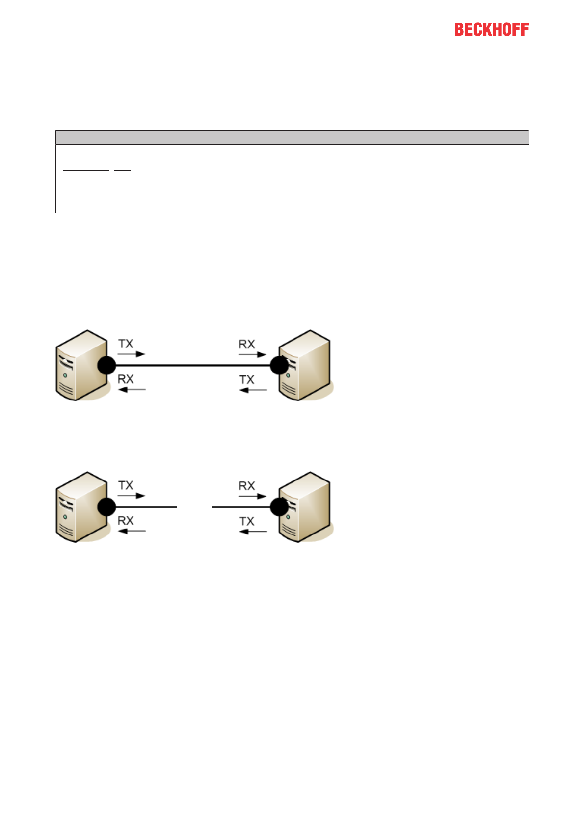
An Ethernet connection is a managed point-to-point connection between two intelligent end devices.
Fig.19: Point-to-point connection between two Ethernet devices
Both devices send a so-called idle sample to their Ethernet connection. The link has been established if a
corresponding sample is received. Both devices then know that they can use this connection. If the
connection is interrupted, the link is lost and both devices are notified.
Fig.20: Interrupted point-to-point connection
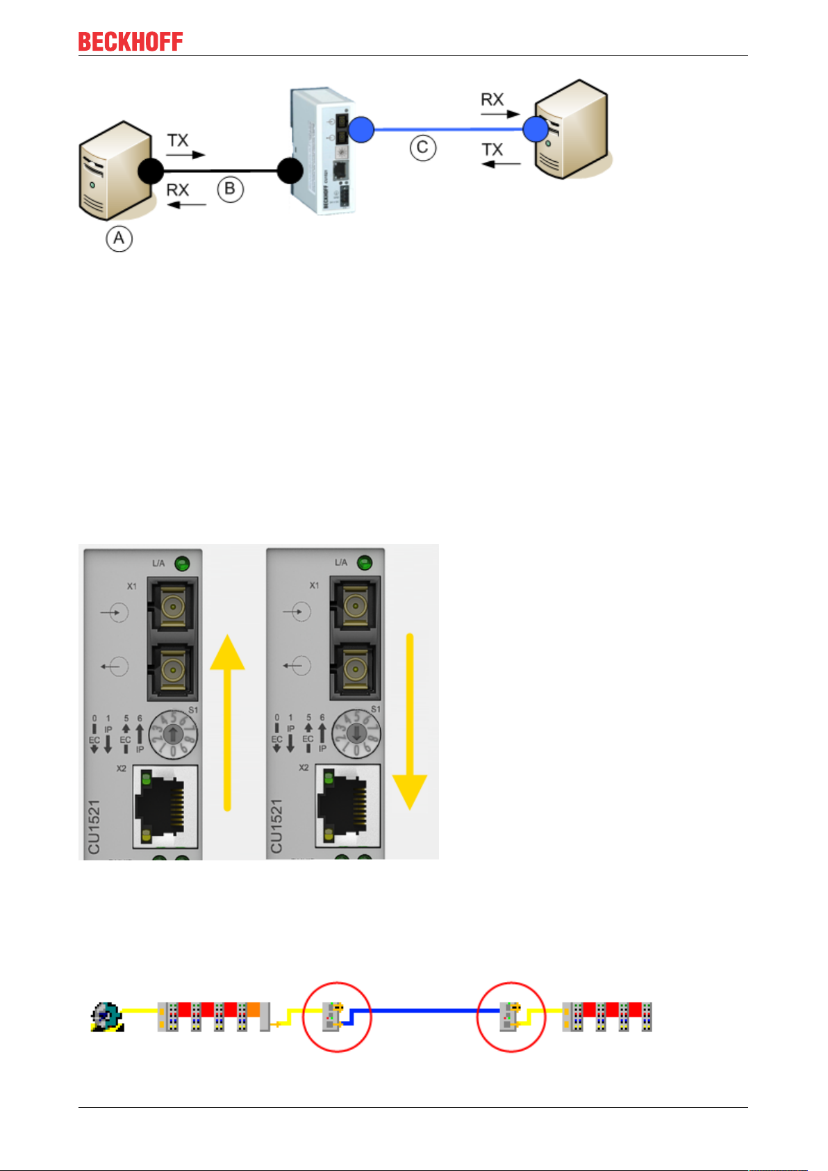
If a media converter is placed between the two stations, it too becomes an intelligent transmitter/receiver. If
connection C is interrupted, device A would not necessarily be informed and would continue to send data to
the converter via the existing link B, and the data would "trickle away". The CU15x1 therefore supports Link
Loss Forwarding (LLF) in a selected direction. The notification is indicated by a label on the CU15x1. If the
converter detects an interruption of connection C in switch setting 1 in Fig. Interposed media converter in the
Ethernet connection, it also interrupts link B.
CU1521-xxxx, CU156126 Version: 2.4
Page 27
Commissioning/application notes
Fig.21: Interposed media converter in the Ethernet connection
In both IP settings the CU15x1 operates as a store and forward network device with checksum function.
Frames that are faulty (CRC error), too short (< 64 bytes) or too long (> 1536 bytes) are not passed on.
Used for: EtherCAT 100Mbit
Other characteristics are required if it is used as a media converter in an EtherCAT network:
• Consistently low delay in the frame transit, irrespective of frame length
• Fast link detection when the connection is established and interrupted
• Identification as separate EtherCAT device with diagnostic function
EtherCAT slaves process the EtherCAT telegrams in forward direction from the perspective of the master.
Accordingly, in the CU15x1 the forward direction may be X1 --> X2 or X2 --> X1, depending on the
application. It has to be set at the rotary switch prior to commissioning. The direction of the arrow of S1
indicates the set forward direction.
Fig.22: Setting the forward direction at the media converter
Make sure the rotary switch is set to the right position, so that the CU15x1 operates in forward direction. For
example, in Fig. Copper -> optical fiber-> copper operation of two media converters, the CU15x1 on the left
operates as a copper --> optical fiber converter (rotary switch position 5), the CU15x1 on the right operates
as an optical fiber --> copper converter (rotary switch position 0).
Fig.23: Copper -> optical fiber-> copper operation of two media converters
CU1521-xxxx, CU1561 27Version: 2.4
Page 28

Commissioning/application notes
If the opposite direction of rotation is set, the subsequent behavior depends on the EtherCAT master. The
scanned CU15x1 may be inserted at a different position in the topology, or an INIT_VPRS error message of
the EtherCAT master may occur.
Earthing/Shielding
The FE contact on the supply socket must be directly connected to the mounting rail contact. During
assembly, always take care of a conductive connection to the mounting rail.
Fig.24: Internal earthing concept
Firmware update
A firmware update via EtherCAT is not possible for devices of the CU15x1 series
General notes
The CU15x1 deals with setting the rotary switch when the supply voltage is applied, unless the rotary switch
is in an invalid position. In this case the CU15x1 deals with the setting when the rotary switch reaches a valid
position for the first time.
If the rotary switch is moved during valid operation, the CU15x1 does not alter its function but indicates this
state through its LED, see Diagnostics [}24]. The switch setting must be rectified before the voltage is re-
applied!
Fig.25: Rotary switch
Slanting installation of the optical fiber socket in the CU15x1 reduces the bending radius of the optical fiber
cable during connection in the control cabinet (Fig. Slanting installation of the optical fiber socket).
CU1521-xxxx, CU156128 Version: 2.4
Page 29

Fig.26: Slanting installation of the optical fiber socket
Commissioning/application notes
CU1521-xxxx, CU1561 29Version: 2.4
Page 30

Commissioning/application notes
5.2 Notes on converters with RJ45 fiber-optic connection
Fig.27: CU1521
Mounting rail installation
Mounting
Please ensure that the CU15x1 engages properly on the mounting rail.
See Mounting rail installation [}22] and Recommended mounting rails [}23].
5.2.1 Principles of fiber-optic technology
When using fiber-optic cables for the transmission of data, there are various factors that influence the signal
transmission and have to be observed in order to guarantee reliable transmission. Important principles of
fiber-optic technology are described below.
Attenuation
Less light reaches the end of a connection with fiber-optic cables than is input at the start of the connection.
This loss of light between the start and end of the transmission link is called attenuation. The attenuation
between two points is often stated in decibels (dB). However, the decibel is not a unit, but a ratio – in the
case of a fiber-optic cable it is the ratio of the light energy at the start of the connection to that at the end. It is
one tenth of a Bel (B) (1 B = 10 dB). In general, decibel indicates a power level LP from the ratio of one
power P1 to another power P2.
• LP[dB] = 10*log10(P1/P2)
A positive power factor is a signal amplification, a negative power factor conversely a weakening or
attenuation of the signal.
CU1521-xxxx, CU156130 Version: 2.4
Page 31
Commissioning/application notes
The attenuation of a fiber-optic connection is essentially determined by three influencing factors. These
influencing factors are the attenuation in the fiber-optic, the attenuation in the connector and the attenuations
that result from the splices in the fiber-optic connection. The total attenuation is therefore given by
• Fiber-optic link attenuation [dB] = fiber loss attenuation [dB] + connector insertion attenuation [dB] +
splice insertion attenuation [dB]
Where
• fiber loss attenuation [dB] = fiber attenuation coefficient [dB/km)] x length [km]
• connector insertion attenuation [dB] = number of connectors x connector insertion attenuation [dB]
• splice insertion attenuation [dB] = number of splices x splice insertion attenuation [dB]
Dispersion
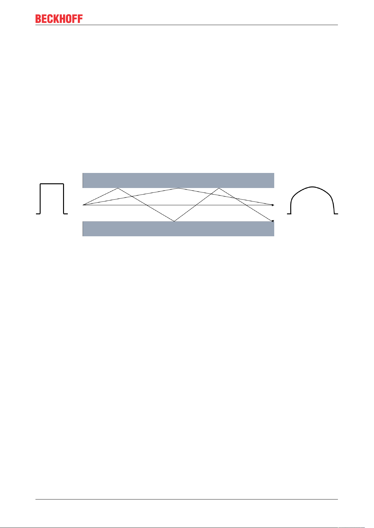
A further influence that needs to be observed with the signal transmission is the dispersion. Dispersion
describes the spreading or widening of a light pulse. Due to propagation differences resulting in the fiberoptic cable from different injection angles of the light waves, the optical pulse widens and is therefore wider
at the output than at the input. The longer the transmission link, the greater the dispersion.
Fig.28: Dispersion
If higher data rates are to be transmitted by the fiber-optic cable, the pulses must be sent faster at the input.
What may happen then, however, is that pulses at the output run into one another and can no longer be
distinguished from one another. The dispersion thus limits the maximum bandwidth of the fiber-optic
connection.
The maximum bandwidth is specified in the data sheet for a fiber-optic cable as the bandwidth/length ratio in
the unit MHz*km. Therefore, the longer a transmission link, the smaller the available bandwidth. The
bandwidth/length ratio or product is always specified in the data sheet for a fiber-optic cable. The length of
the transmission link can then be calculated with the necessary bandwidth.
s [km] = bandwidth [MHz] / bandwidth/length ratio [MHz/km]
Further influences on the signal transmission
In addition to the main influences (attenuation and dispersion) that limit the transmission link, care must be
taken when installing and maintaining fiber-optic transmission links.
Sharp kinks and micro-bends in the fiber-optic lead to additional reflections in the fiber, as a result of which
the influences of the attenuation and dispersion are increased. The specified bending radii of fiber-optic
cables must be adhered to.
Poorly installed connectors also have a great influence on the signal quality. In case of poor connections, the
fiber-optic may be too far away from the connecting piece, so that the light waves do not enter the fiber at the
right angle of entry.
The third influence on the signal transmission that needs to be observed is soiling of, or damage to the ends
of optical fibers. Due to the size of the fibers, often just 125µm, dirt or damage cannot be discerned with the
naked eye. Only a microscope with a sufficient magnification (at least factor 100) enables the fiber ends to
be checked. To prevent soiling, the cable cap supplied with the cable should always be fitted to the fiber end.
CU1521-xxxx, CU1561 31Version: 2.4
Page 32

Commissioning/application notes
Power and attenuation budget
The power budget specifies the minimum power present between transmitter and receiver. The attenuation
budget, conversely, describes the attenuation present between transmitter and receiver due to the three
attenuation influences - fiber, connectors and splices - described above.
Transceivers (from the words transmitter and receiver) are installed in fiber-optic transmitters and/or
receivers. This transceiver is a combined transmitting and receiving device. The data sheet for the
transceiver contains two values that are necessary for the calculation of the power budget. These values are
the minimum output power of the transmitter and the maximum sensitivity of the receiver. Therefore, the
worst case, i.e. the lowest power between transmitter and receiver, is always considered. Both values are
often specified in the unit decibel milliwatt (dBm). dBm describes a power level in relation to a reference
value of 1mW.
• LP[dB] = 10*log10(P1/1 mW)
0 dBm then corresponds to a power value of 1 mW, positive dBm values indicate power values >1mW and
negative dBm values indicate power values <1mW.
The difference between the maximum output power and the minimum sensitivity at the input results in the
power level.
• Power level = minimum output power - maximum sensitivity
The attenuation level results from the influences on the attenuation described above.
• Attenuation level [dB] = fiber loss attenuation [dB] + connector insertion attenuation [dB] + splice
insertion attenuation [dB]
Fig.29: Power and attenuation budget
The attenuation level must not exceed the power level. A power buffer of >3dB is recommended so that
long-term operation is possible over many years despite power losses. Sources located in the transmitter
can age and lose power, connectors or splices can deteriorate, or connectors can become dirty if they are
opened for diverting or testing. If cables are inadvertently cut through, excess play is required in order to
accommodate splices for reconnecting.
CU1521-xxxx, CU156132 Version: 2.4
Page 33

Commissioning/application notes
Example calculation of power and attenuation budget
In an example calculation, the power and attenuation budget is to be calculated for a transmission link of
2.1km in length between an EK1501-0000 and an EK1521-0000 with a multimode fiber in the strength
50/125µm. The two fiber-optic couplers under consideration have the same transceiver. The optical data are
given in the Technical data for the EK1521.
First of all, the power budget existing between the two couplers must be calculated:
Power budget
Parameter Value
Minimum output power [50/125µm] -23.5dBm
Maximum sensitivity -31dBm
Power budget 7.5dBm
In the next step, the attenuation budget, i.e. the attenuation over the entire transmission link, must be
calculated. A multimode fiber in the strength 50/125µm from Beckhoff (ZK1091-1001-xxxx) is used for this
example. A maximum attenuation of 0.8dB/km at a wavelength of 1300nm is specified in the data sheet for
the fiber-optic cable. The cable is connected at both ends via an SC connector. The typical attenuation value
of SC connectors is 0.25 dB, but it should nevertheless be checked for the specific application. Three splices
were made over the entire link. A typical attenuation of 0.3dB can be assumed per splice connection;
however, the attenuation of a splice is dependent on its quality. The attenuation budget must be calculated
from these values in the following.
Attenuation budget
Parameter Number Value
Fiber loss attenuation (0.8dB/km) 2.1km 1.68dB
Connector insertion attenuation
(0.25dB)
Splice insertion attenuation (0.3dB) 3 0.9dB
Attenuation budget 3.08dB
If the attenuation budget is now subtracted from the power budget, a power buffer of 4.42dB results. This is
greater than 3dB and is therefore sufficient as a buffer for most applications, so that an additional splice or
slight soiling of the fiber would not lead to failure of the data transmission.
If several values are given for a parameter in the data sheet for transceivers, cables or connectors, the worst
value should always be taken and used for the calculation.
For the transmission link under consideration, the bandwidth/length ratio specified in the data sheet for the
fiber should always be considered in addition to the attenuation and, as shown above, one should calculate
whether the implementation of the length of the transmission link is possible with the desired bandwidth and
the fiber.
Evaluation of a fiber-optic transmission link by means of measurement
As described in the previous section, a fiber-optic transmission link can be described and evaluated with
parameters from data sheets. In order to obtain a real result for the attenuation over the entire link, however,
the link must be measured using an optical power meter (OPM). The power at the end of the transmission
link can be measured with an OPM.
2 0.5dB
When measuring with an OPM, it is essential to ensure that only the required adapter (FC,SC,…) is
screwed to the OPM. If several adapters are screwed above one another to the OPM, the distance between
the connector and the detector in the OPM is too large, with the result that lower power values are displayed
(greater attenuation than actually exists).
CU1521-xxxx, CU1561 33Version: 2.4
Page 34

Commissioning/application notes
OPM without adapter OPM with FC adapter screwed on
OPM with SC adapter screwed on OPM with FC and SC adapter screwed on -
WRONG
CU1521-xxxx, CU156134 Version: 2.4
Page 35

Commissioning/application notes
5.2.2 Notes on suitable optical fiber cables
General information on optical fiber types
Optical fiber are available as multimode and single mode types with different step and graded indices.
Step and graded index
Optical fiber cables consist of 2 concentric materials, the core and cladding, plus a protective (colored)
jacket. The core and the cladding have a different index of refraction, causing the light waves (modes; a
mode is a natural wave in the optical fiber) to be reflected back into the core at the boundary. Due to the step
change in the index of refraction this type of fiber is referred to as step index. A gradual/parabolic transition
between the index of refraction in the core and the coating (referred to as graded index) can be achieved by
mixing the materials. In a graded index fiber the modes are gradually diffracted back to the core, leading to
propagation-time compensation and significantly higher quality of the light pulse at the outlet compared with
a multimode step index fiber, where the different light modes have different signal run times (mode
dispersion) with associated front distortion.
Single mode
Single-mode fibers have a very thin core (9 µm) and therefore conduct only a single mode of the light used,
with high signal quality and virtually without mode dispersion. They are only available as step index fibers.
Due to the high signal quality they are suitable for large transmission bandwidths > 10 GHz*km and
distances > 50 km. The refractive index profile of single-mode fibers is dimensioned such that the multipath
propagation (intermodal dispersion), which is a problem with multi-mode fibers, is omitted – the signal light
propagates in a single-mode fiber only in a single guided fiber mode, hence the designation ‘single-mode’.
This makes considerably larger transmission distances and/or bandwidths possible, and the limiting effect
that arises next is the color distortion of the transmitted mode.
Multimode
Multimode fiber-optics are manufactured as step index or graded index. Step index multimode fiber cables
are suitable for transmission bandwidths up to 100 MHz*km and distances up to 1 km. Graded index
multimode fiber cables with core diameters between 50 and 62.5 µm reach transmission bandwidths > 1
GHz*km and ranges > 10 km. Multimode means that the core of the fiber-optic cable is thick enough to
enable several light modes to propagate reflectively in the cable.
There are different types of multimode fiber-optics, which are optimized for different wavelengths or
transmission sources. Through the optimization of the fibers for different wavelengths, the attenuation differs
with different transmission rates and the bandwidth/length ratio differs for the different fiber types. The exact
values must be taken from the data sheet for the selected fiber in order to check whether the use of the
selected fiber is wise.
• OM1: 62.5/125µm, optimized for 1300nm LEDs
• OM2: 50/125µm, optimized for 1300nm LEDs
• OM3: 50/125µm, optimized for 850nm VCSEL (vertical-cavity surface-emitting laser)
• OM4: 50/125µm, optimized for 850nm VCSEL (vertical-cavity surface-emitting laser)
CU1521-xxxx, CU1561 35Version: 2.4
Page 36

Commissioning/application notes
5.2.3 Application with CU1521 and CU1521-0010
Application with CU1521 and CU1521-0010
The CU1521, CU1521-0010 are intended for application with optical fiber cables with the following
characteristics:
• SC duplex connector.
• CU1521: Duplex multimode 50/125 µm or 62.5/125 µm (inner/outer core diameter). The use of both
diameters is possible. However, the use of 50/125 µm is recommended due to the lower attenuation.
• CU1521-0010: Duplex single-mode 9/125 µm (inner/outer core diameter). A typically usable cable can
be manufactured according to the specification ITU-T G.652.D (0.4.4dBm/km at 1300nm).
Recommended connectors
The use of SC/PC connectors is recommended for connecting to the CU1521, CU1521-0010. The
advantage of the "PC" (physical contact) version of this connector is the crowned end face, which
allows the region of the fiber core that is relevant to transmission to be optimally joined when the
connector is pushed together. Other versions include, for instance, the SC/UPC (ultra-polish PC),
SC/HRL (high return loss) and the SC/APC plug (angled physical contact).
An additional feature of these connectors is that light that is reflected by the connector's end face,
which is at an angle of about 8° to the fiber axis, is refracted from the core by the cladding glass into
the air. This avoids interference with the data transmission, optimizing the core size of the backscatter.
50/125 µm or 62.5/125 µm
The use of both diameters is possible. However, the use of 50/125 µm is recommended due to the
lower attenuation.
In optical fibers the wavelengths 850 nm and 1300 nm are usually used for data transfer. Commercially
available optical fiber cables are usually optimized for application in one of these ranges, since signal
attenuation is frequency-dependent (like in copper cable), so that large ranges of several km can be
achieved for the respective wavelength. In general, optical fiber cables exhibit a lower attenuation at a
wavelength of 1300 nm than at 850 nm.
In the CU1521, CU1521-0010 a transceiver with the wavelength of 1300 nm is used.
Range and bandwidth product
Optical fiber cables are available in different qualities from reputable manufacturers. One of the relevant parameters for the user is the frequency-dependent bandwidth product of a cable, specified in
[MHz*km]. The greater the bandwidth product, the lower the attenuation, and therefore the larger
the range that can be achieved with this cable (see ITU-T G-651). To maximize the range with the
CU1521, CU1521-0010 optical fiber cables with a maximum high bandwidth product at 1300 nm
should therefore be used. We recommend optical fiber cables from the OM2 class (EN50173:2002).
Standard optical fiber cables have a minimum bandwidth product of 500 MHz*km at 1300 nm,
higher-quality cables are suitable for distances > 500 m over > 1000 MHz*km.
For maximum distances the remote counterpart of the CU1521, CU1521-0010 should also support
such ranges.
Installation notes
The following parameters must be taken into account in the installation of optical fiber cables
• permitted bending radius
• permitted tensile strength
• sensitivity of the exposed contact ends
Further information can be found in the following documents:
• ITU recommendation ITU-T G.651 - G.655
• EN 50173:2002
• EN 60793-2
CU1521-xxxx, CU156136 Version: 2.4
Page 37

Commissioning/application notes
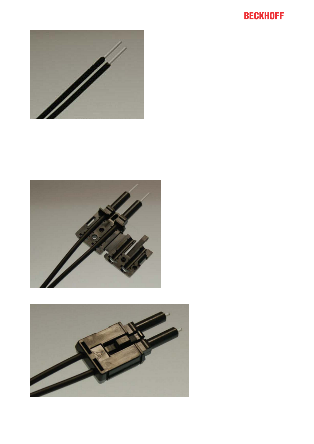
5.2.4 Connecting and disconnecting the fiber cable
Connecting and disconnecting the optical fiber cable
NOTE
Risk of damage to the cable!
To disconnect the optical fiber cable always pull the connector to release the locking mechanism - never
pull the optical fiber cable itself.
Crossover cables
Please note that when connecting the CU1521, CU1521-0010 to the remote station, it may be necessary to use "crossed" cables in order to establish a connection.
Practical tip:
The infrared light emission can be made visible with some digital/mobile phone cameras (see figure
Visualization of infrared light at the SC Duplex connector), whether the camera used can receive
the IR wavelengths; must be checked in each individual case. Avoid 'light meeting light' when connecting the optical fiber cable (Tx -> Tx). In this case no connection can be established, and you
have to cross the cables (Tx -> Rx).
Fig.30: Visualization of infrared light at the SC duplex connector
Use of blind plugs
To protect the transceiver from environmental influences, unused connection socket should be
sealed with the blind plugs provided! See Fig.: Blind plugs in unused sockets
CU1521-xxxx, CU1561 37Version: 2.4
Page 38

Commissioning/application notes
Fig.31: Blind plugs in unused sockets
5.3 Notes on converters with RJ45 POF connection
5.3.1 Notes regarding suitable POF cables
General information about POF cables
The standard polymer fiber is 1 mm thick and consists of a 0.98 mm thick core made of polymethyl
methacrylate (PMMA) as well as a thin sheath. In order to enable the guidance of light using the effect of
total reflection in the core, the usually very thin sheath consists of fluorinated PMMA, which has a low
refractive index. The core diameters lie between 0.06 mm and 1 mm, as a result of which simple plug
connections are easy to implement. Furthermore, the splicing process often used for the connection of glass
fibers and the unnecessarily high expenditure associated with it can usually be dispensed with. The
maximum operating temperature of standard POF is approximately 60°C and has a refraction profile with
step index (SI-POF). The refractive index of the core material is around 1.49 and that of the sheath around
1.41. The difference determines the numerical aperture (NA) and thus the maximum propagation angle. With
a difference of 5% this angle is about 20 degrees in relation to the fiber axis, which leads to a reduction in
the bandwidth.
Due to the simple and almost universally applicable connection techniques compared to glass fibers, POFs
are used in particular for short transmission distances, such as inside rooms, technical equipment,
mechanical systems or cars.
POFs have an attenuation of about 140 dB/km at a wavelength of 650 Nm, so that a maximum data
transmission distance of 50 m can be achieved when used with the CU1561.
Insertion of additional connectors in the route increases the signal attenuation. For each additional
connector, the maximum permitted distances typically reduces by 6.5 m.
CU1521-xxxx, CU156138 Version: 2.4
Page 39

Commissioning/application notes
Application with CU1561
Recommended plug connectors and POF cables
For the connection of the CU1561 it is recommended to use the connector set ZS1090-0008 [}40]
(Versatile Link Duplex plugs) in conjunction with a duplex polymer fiber with an outside diameter of
2 x 2.2 mm (Z1190), which are available from Beckhoff.
Installation notes
Among other things, the following items should be observed when laying POF cables:
• permissible bending radius (in general r ≥ 25 mm, refer to the manufacturer’s data!)
• permitted tensile strength
• sensitivity of the exposed contact ends
5.3.2 Connecting and disconnecting the POF cable
To connect the cable, insert the plug (available as an accessory in the connector set ZS1090-0008) into the
connection opening until it audibly latches.
Fig.32: Latching lug with release catch on the POF duplex plug
To release the connector activate the release device with the latching lug. This is located on the right-hand
side of the connector (see Fig. Latching lug with release catch on the POF duplex plug)
NOTE
Risk of damage to the cable!
To release the cable, press the release catch on the plug and pull the plug at the same time – never pull by
the POF cable alone!
NOTE
TX / Rx channel assignment
During cable assembly [}40] note the assignment of the optical channels in the connection socket. In the
case of the CU1561 the light-emitting transmitter channel (Tx) is the lower outlet in the connection socket
(Fig. Transmitter channel of the CU1561).
Be sure to observe the safety instructions [}45] for class 1 lasers!
CU1521-xxxx, CU1561 39Version: 2.4
Page 40

Commissioning/application notes
Fig.33: Transmitter channel of the CU1561
NOTE
Use of blind plugs
In order to avoid accidents due to glare (Class 1 laser, please observe the safety instructions [}45]) and
to protect the transceiver against environmental influences, unused sockets should be sealed using the
blind plugs provided (Fig. Blind plugs in unused sockets)
Fig.34: Blind plugs in unused sockets
5.4 Notes regarding assembly of POF cables with the connector set ZS1090-0008
Table of contents
• Step-by-step instructions for assembling the POF cable [}41]
1. Stripping the POF cable [}41]
2. Attaching the connector [}42]
3. Grinding and polishing [}43]
4. Fine polishing [}44]
CU1521-xxxx, CU156140 Version: 2.4
Page 41

Fig.35: Duplex connector set ZS1090-0008
Commissioning/application notes
The duplex connector set ZS1090-0008 from Beckhoff consists of 10 duplex Versatile Link connectors and
several sheets of abrasive paper and polishing paper.
Step-by-step instructions for assembling the POF cable
The following step-by-step guide describes the correct assembly of a POF cable with a Versatile Link duplex
connector. The connectors are attached to the cable ends with standard tools such as cutter knife or wire
strippers. Polish the assembled cable with the polishing set provided with the connector set, consisting of a
plastic sanding gauge, sheets of abrasive paper with grain size 600 and pink polishing sheets. Once
assembled, the connector can be used right away.
Materials required:
1. POF cable (Polymeric Optical Fiber, e.g. Z1190 from Beckhoff)
2. Cutter knife or shears
3. Wire strippers
4. Polishing set (included with connector set ZS1090-0008 from Beckhoff)
5. Versatile Link duplex connector (included in connector set ZS1090-0008 from Beckhoff)
1. Stripping the POF cable
The cable should be split over a length between 100 and 150mm from the cable end, so that the following
steps can be carried out properly.
Once you have shortened the cable to the required length, use the wire strippers to remove approx. 7 mm of
the external sheathing of the individual wires. The two cable ends should be stripped over approximately the
same length. (Fig. POF cable stripped over the same length).
CU1521-xxxx, CU1561 41Version: 2.4
Page 42
Commissioning/application notes
Fig.36: POF cable stripped over the same length
2. Attaching the connector
Push the two cable ends into the connector and the connector back until it stops. The fibers should now
protrude no more than 1.5 mm out of the front openings (Fig. Cable inserted in the connector).
Close the connector by folding the upper and lower halves together until they engage (Fig. Closed
connector).
Fig.37: Cable inserted in the connector
Fig.38: Closed connector
CU1521-xxxx, CU156142 Version: 2.4
Page 43

Commissioning/application notes
When inserting the wires into the connector ensure the optical channels are crossed (Tx1 --> Rx2; Tx2 -->
Rx1). The 'nose' at the connector hinge can be used as a guide (Fig. Correctly connected optical channels).
Fig.39: Correctly connected optical channels
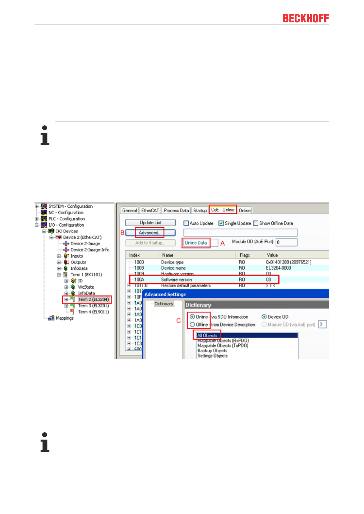
3. Grinding and polishing
Any fibers protruding more than 1.5mm from the connector should be shortened with a cutter knife or a pair
of scissors.
Now push the connector fully into the sanding gauge, so that the ends to be polished protrude from the lower
side (Fig. Sanding gauge with protruding fiber ends). The sanding gauge is suitable for polishing one or two
simplex connectors or a duplex connector.
Fig.40: Sanding gauge with protruding fiber ends
Wear indicator
The wear indicator of the sanding gauge consists of four points on the underside. The sanding
gauge should be replaced when one of these points is no longer visible.
Now press the sanding gauge onto the abrasive paper with uniform pressure and as perpendicular as
possible. In order to achieve a uniform result, use the abrasive paper in the form of a figure of 8 (Fig.
Polishing in the form of a figure "8"), until the fibers are flush with the sanding gauge. Then clean the sanding
gauge and the connector from below with a soft, dry cloth.
CU1521-xxxx, CU1561 43Version: 2.4
Page 44
Commissioning/application notes
Fig.41: Polishing in the form of a figure of "8"
4. Fine polishing
Now use the pink polishing sheet for fine polishing in the same manner. Apply the connector with the
sanding gauge to the matt side of the polishing sheet with slight pressure and polish in the form of a figure of
8 up to 25 times. After the procedure the fiber end should be flat, smooth and clean.
Improving the transfer performance by fine polishing
Fine polishing with a polishing sheet can improve the transfer performance between the transmitter
and the receiver or in the cable joint by up to 0.5 dB compared with to treatment with abrasive paper
alone. For short transfer distances the polishing step can be omitted.
Fig.42: Fine-polished fibers in the connector
CU1521-xxxx, CU156144 Version: 2.4
Page 45

Appendix
6 Appendix
6.1 Safety instructions and behavioral rules for Class 1 laser
CAUTION
Class 1 laser product – danger of accident due to glare!
The following laser-specific behavioral rules are to be followed for the Class 1 laser products described in
this document:
• The laser beam may not be directed toward persons, since accidents may be caused by glare.
• Do not look into the direct or reflected beam.
• If laser radiation meets the eye, the eyes must be consciously closed and the head turned away from the
beam immediately.
• When using the laser, no optical instruments may be used to view the radiation source, since this can
lead to exposure limit values being exceeded.
• Manipulations (modifications) of the laser device are not permitted.
Fig.43: Note
6.2 Firmware compatibility
The CU1521-00x0 and CU1561-0000 converters have no firmware.
6.3 Firmware Update EL/ES/EM/ELM/EPxxxx
This section describes the device update for Beckhoff EtherCAT slaves from the EL/ES, ELM, EM, EK and
EP series. A firmware update should only be carried out after consultation with Beckhoff support.
Storage locations
An EtherCAT slave stores operating data in up to three locations:
• Depending on functionality and performance EtherCAT slaves have one or several local controllers for
processing I/O data. The corresponding program is the so-called firmware in *.efw format.
• In some EtherCAT slaves the EtherCAT communication may also be integrated in these controllers. In
this case the controller is usually a so-called FPGA chip with *.rbf firmware.
• In addition, each EtherCAT slave has a memory chip, a so-called ESI-EEPROM, for storing its own
device description (ESI: EtherCAT Slave Information). On power-up this description is loaded and the
EtherCAT communication is set up accordingly. The device description is available from the download
area of the Beckhoff website at (https://www.beckhoff.de). All ESI files are accessible there as zip files.
Customers can access the data via the EtherCAT fieldbus and its communication mechanisms. Acyclic
mailbox communication or register access to the ESC is used for updating or reading of these data.
CU1521-xxxx, CU1561 45Version: 2.4
Page 46

Appendix
The TwinCAT System Manager offers mechanisms for programming all three parts with new data, if the
slave is set up for this purpose. Generally the slave does not check whether the new data are suitable, i.e. it
may no longer be able to operate if the data are unsuitable.
Simplified update by bundle firmware
The update using so-called bundle firmware is more convenient: in this case the controller firmware and the
ESI description are combined in a *.efw file; during the update both the firmware and the ESI are changed in
the terminal. For this to happen it is necessary
• for the firmware to be in a packed format: recognizable by the file name, which also contains the
revision number, e.g. ELxxxx-xxxx_REV0016_SW01.efw
• for password=1 to be entered in the download dialog. If password=0 (default setting) only the firmware
update is carried out, without an ESI update.
• for the device to support this function. The function usually cannot be retrofitted; it is a component of
many new developments from year of manufacture 2016.
Following the update, its success should be verified
• ESI/Revision: e.g. by means of an online scan in TwinCAT ConfigMode/FreeRun – this is a convenient
way to determine the revision
• Firmware: e.g. by looking in the online CoE of the device
NOTE
Risk of damage to the device!
ü Note the following when downloading new device files
a) Firmware downloads to an EtherCAT device must not be interrupted
b) Flawless EtherCAT communication must be ensured. CRC errors or LostFrames must be avoided.
c) The power supply must adequately dimensioned. The signal level must meet the specification.
ð In the event of malfunctions during the update process the EtherCAT device may become unusable and
require re-commissioning by the manufacturer.
6.3.1 Device description ESI file/XML
NOTE
Attention regarding update of the ESI description/EEPROM
Some slaves have stored calibration and configuration data from the production in the EEPROM. These are
irretrievably overwritten during an update.
The ESI device description is stored locally on the slave and loaded on start-up. Each device description has
a unique identifier consisting of slave name (9 characters/digits) and a revision number (4 digits). Each slave
configured in the System Manager shows its identifier in the EtherCAT tab:
CU1521-xxxx, CU156146 Version: 2.4
Page 47

Appendix
Fig.44: Device identifier consisting of name EL3204-0000 and revision -0016
The configured identifier must be compatible with the actual device description used as hardware, i.e. the
description which the slave has loaded on start-up (in this case EL3204). Normally the configured revision
must be the same or lower than that actually present in the terminal network.
For further information on this, please refer to the EtherCAT system documentation.
Update of XML/ESI description
The device revision is closely linked to the firmware and hardware used. Incompatible combinations
lead to malfunctions or even final shutdown of the device. Corresponding updates should only be
carried out in consultation with Beckhoff support.
Display of ESI slave identifier
The simplest way to ascertain compliance of configured and actual device description is to scan the
EtherCAT boxes in TwinCAT mode Config/FreeRun:
Fig.45: Scan the subordinate field by right-clicking on the EtherCAT device
If the found field matches the configured field, the display shows
CU1521-xxxx, CU1561 47Version: 2.4
Page 48

Appendix
Fig.46: Configuration is identical
otherwise a change dialog appears for entering the actual data in the configuration.
Fig.47: Change dialog
In this example in Fig. Change dialog, an EL3201-0000-0017 was found, while an EL3201-0000-0016 was
configured. In this case the configuration can be adapted with the Copy Before button. The Extended
Information checkbox must be set in order to display the revision.
Changing the ESI slave identifier
The ESI/EEPROM identifier can be updated as follows under TwinCAT:
• Trouble-free EtherCAT communication must be established with the slave.
• The state of the slave is irrelevant.
• Right-clicking on the slave in the online display opens the EEPROM Update dialog, Fig. EEPROM
Update
CU1521-xxxx, CU156148 Version: 2.4
Page 49

Appendix
Fig.48: EEPROM Update
The new ESI description is selected in the following dialog, see Fig. Selecting the new ESI. The checkbox
Show Hidden Devices also displays older, normally hidden versions of a slave.
Fig.49: Selecting the new ESI
A progress bar in the System Manager shows the progress. Data are first written, then verified.
The change only takes effect after a restart.
Most EtherCAT devices read a modified ESI description immediately or after startup from the INIT.
Some communication settings such as distributed clocks are only read during power-on. The EtherCAT slave therefore has to be switched off briefly in order for the change to take effect.
6.3.2 Firmware explanation
Determining the firmware version
Determining the version on laser inscription
Beckhoff EtherCAT slaves feature serial numbers applied by laser. The serial number has the following
structure: KK YY FF HH
KK - week of production (CW, calendar week)
YY - year of production
FF - firmware version
HH - hardware version
CU1521-xxxx, CU1561 49Version: 2.4
Page 50
Appendix
Example with ser. no.: 12 10 03 02:
12 - week of production 12
10 - year of production 2010
03 - firmware version 03
02 - hardware version 02
Determining the version via the System Manager
The TwinCAT System Manager shows the version of the controller firmware if the master can access the
slave online. Click on the E-Bus Terminal whose controller firmware you want to check (in the example
terminal 2 (EL3204)) and select the tab CoE Online (CAN over EtherCAT).
CoE Online and Offline CoE
Two CoE directories are available:
• online: This is offered in the EtherCAT slave by the controller, if the EtherCAT slave supports this.
This CoE directory can only be displayed if a slave is connected and operational.
• offline: The EtherCAT Slave Information ESI/XML may contain the default content of the CoE.
This CoE directory can only be displayed if it is included in the ESI (e.g. “Beckhoff EL5xxx.xml”).
The Advanced button must be used for switching between the two views.
In Fig. Display of EL3204 firmware version the firmware version of the selected EL3204 is shown as 03 in
CoE entry 0x100A.
Fig.50: Display of EL3204 firmware version
In (A) TwinCAT 2.11 shows that the Online CoE directory is currently displayed. If this is not the case, the
Online directory can be loaded via the Online option in Advanced Settings (B) and double-clicking on
AllObjects.
6.3.3 Updating controller firmware *.efw
CoE directory
The Online CoE directory is managed by the controller and stored in a dedicated EEPROM, which
is generally not changed during a firmware update.
Switch to the Online tab to update the controller firmware of a slave, see Fig. Firmware Update.
CU1521-xxxx, CU156150 Version: 2.4
Page 51

Appendix
Fig.51: Firmware Update
Proceed as follows, unless instructed otherwise by Beckhoff support. Valid for TwinCAT2 and 3 as
EtherCAT master.
• Switch TwinCAT system to ConfigMode/FreeRun with cycle time >= 1 ms (default in ConfigMode is
4ms). A FW-Update during real time operation is not recommended.
• Switch EtherCAT Master to PreOP
• Switch slave to INIT (A)
• Switch slave to BOOTSTRAP
CU1521-xxxx, CU1561 51Version: 2.4
Page 52

Appendix
• Check the current status (B, C)
• Download the new *efw file (wait until it ends). A pass word will not be neccessary usually.
• After the download switch to INIT, then PreOP
• Switch off the slave briefly (don't pull under voltage!)
• Check within CoE 0x100A, if the FW status was correctly overtaken.
6.3.4 FPGA firmware *.rbf
If an FPGA chip deals with the EtherCAT communication an update may be accomplished via an *.rbf file.
• Controller firmware for processing I/O signals
• FPGA firmware for EtherCAT communication (only for terminals with FPGA)
The firmware version number included in the terminal serial number contains both firmware components. If
one of these firmware components is modified this version number is updated.
Determining the version via the System Manager
The TwinCAT System Manager indicates the FPGA firmware version. Click on the Ethernet card of your
EtherCAT strand (Device 2 in the example) and select the Online tab.
The Reg:0002 column indicates the firmware version of the individual EtherCAT devices in hexadecimal and
decimal representation.
CU1521-xxxx, CU156152 Version: 2.4
Page 53

Appendix
Fig.52: FPGA firmware version definition
If the column Reg:0002 is not displayed, right-click the table header and select Properties in the context
menu.
Fig.53: Context menu Properties
The Advanced Settings dialog appears where the columns to be displayed can be selected. Under
Diagnosis/Online View select the '0002 ETxxxx Build' check box in order to activate the FPGA firmware
version display.
CU1521-xxxx, CU1561 53Version: 2.4
Page 54

Appendix
Fig.54: Dialog Advanced Settings
Update
For updating the FPGA firmware
• of an EtherCAT coupler the coupler must have FPGA firmware version 11 or higher;
• of an E-Bus Terminal the terminal must have FPGA firmware version 10 or higher.
Older firmware versions can only be updated by the manufacturer!
Updating an EtherCAT device
The following sequence order have to be met if no other specifications are given (e.g. by the Beckhoff
support):
• Switch TwinCAT system to ConfigMode/FreeRun with cycle time >= 1ms (default in ConfigMode is
4ms). A FW-Update during real time operation is not recommended.
CU1521-xxxx, CU156154 Version: 2.4
Page 55

Appendix
• In the TwinCAT System Manager select the terminal for which the FPGA firmware is to be updated (in
the example: Terminal 5: EL5001) and
click the Advanced Settings button in the EtherCAT tab:
• The Advanced Settings dialog appears. Under ESC Access/E²PROM/FPGA click on Write FPGA
button:
CU1521-xxxx, CU1561 55Version: 2.4
Page 56

Appendix
• Select the file (*.rbf) with the new FPGA firmware, and transfer it to the EtherCAT device:
• Wait until download ends
• Switch slave current less for a short time (don't pull under voltage!). In order to activate the new FPGA
firmware a restart (switching the power supply off and on again) of the EtherCAT device is required.
• Check the new FPGA status
NOTE
Risk of damage to the device!
A download of firmware to an EtherCAT device must not be interrupted in any case! If you interrupt this
process by switching off power supply or disconnecting the Ethernet link, the EtherCAT device can only be
recommissioned by the manufacturer!
6.3.5 Simultaneous updating of several EtherCAT devices
The firmware and ESI descriptions of several devices can be updated simultaneously, provided the devices
have the same firmware file/ESI.
Fig.55: Multiple selection and firmware update
Select the required slaves and carry out the firmware update in BOOTSTRAP mode as described above.
CU1521-xxxx, CU156156 Version: 2.4
Page 57

Appendix
6.4 Support and Service
Beckhoff and their partners around the world offer comprehensive support and service, making available fast
and competent assistance with all questions related to Beckhoff products and system solutions.
Beckhoff's branch offices and representatives
Please contact your Beckhoff branch office or representative for local support and service on Beckhoff
products!
The addresses of Beckhoff's branch offices and representatives round the world can be found on her internet
pages:
http://www.beckhoff.com
You will also find further documentation for Beckhoff components there.
Beckhoff Headquarters
Beckhoff Automation GmbH & Co. KG
Huelshorstweg 20
33415 Verl
Germany
Phone: +49 5246 963 0
Fax: +49 5246 963 198
e-mail: info@beckhoff.com
Beckhoff Support
Support offers you comprehensive technical assistance, helping you not only with the application of
individual Beckhoff products, but also with other, wide-ranging services:
• support
• design, programming and commissioning of complex automation systems
• and extensive training program for Beckhoff system components
Hotline: +49 5246 963 157
Fax: +49 5246 963 9157
e-mail: support@beckhoff.com
Beckhoff Service
The Beckhoff Service Center supports you in all matters of after-sales service:
• on-site service
• repair service
• spare parts service
• hotline service
Hotline: +49 5246 963 460
Fax: +49 5246 963 479
e-mail: service@beckhoff.com
CU1521-xxxx, CU1561 57Version: 2.4
Page 58

Page 59

More Information:
www.beckhoff.de/english/pc_cards_switches/
product_overview_infrastructure.htm
Beckhoff Automation GmbH & Co. KG
Hülshorstweg 20
33415 Verl
Germany
Phone: +49 5246 9630
info@beckhoff.com
www.beckhoff.com
 Loading...