

Beckhoff CPX3915-0010, CPX3919-0010, CPX3921-0010 Installation And Operating Instructions Manual
Page 1

Installation and operating instructions
CPX39xx-0010
Multi-touch Control Panel with CP-Link 4 interface for use in
hazardous locations, zone 2/22
0.1
30.05.2018
Version:
Date:
Page 2

Page 3

Table of Contents
CPX39xx-0010 3Version: 0.1
Table of Contents
1 Notes on the documentation ....................................................................................................................5
1.1 Explanation of symbols......................................................................................................................6
1.2 Documentation issue status ..............................................................................................................7
2 For your safety...........................................................................................................................................8
2.1 Intended use......................................................................................................................................8
2.2 Notes about operation in potentially explosive areas ........................................................................9
2.2.1 Special conditions (ATEX) ................................................................................................. 9
2.2.2 Special conditions (IECEx) .............................................................................................. 10
2.2.3 Marking ............................................................................................................................ 11
2.3 Safety instructions ...........................................................................................................................12
2.4 Staff qualification .............................................................................................................................13
2.5 Operator's responsibility ..................................................................................................................13
3 Transport and storage.............................................................................................................................14
4 Product overview.....................................................................................................................................15
4.1 Access to the interfaces ..................................................................................................................16
4.2 Name plate ......................................................................................................................................18
4.3 Interfaces CPX39xx-0010................................................................................................................19
4.3.1 CP-Link 4 Architecture Description.................................................................................. 19
4.4 Description of the interfaces ............................................................................................................20
4.4.1 Power supply (X101) ....................................................................................................... 20
4.4.2 CP-Link 4 Input (X102) .................................................................................................... 21
4.4.3 Ground............................................................................................................................. 21
5 Mounting and wiring................................................................................................................................22
5.1 Mounting..........................................................................................................................................22
5.1.1 Preparation of the Panel PC ............................................................................................ 22
5.2 Wiring...............................................................................................................................................24
5.2.1 Preparation and protective earthing................................................................................. 24
5.2.2 Connecting....................................................................................................................... 25
5.2.3 Fitting the power supply................................................................................................... 26
6 Operation..................................................................................................................................................27
6.1 Switching the Control Panel on and off ...........................................................................................27
6.2 Touch screen...................................................................................................................................27
6.3 Servicing and maintenance .............................................................................................................28
6.4 Emergency procedures ...................................................................................................................28
6.5 Shutting down..................................................................................................................................28
7 Troubleshooting ......................................................................................................................................29
8 Assembly dimensions.............................................................................................................................30
9 Technical Data .........................................................................................................................................33
10 Appendix ..................................................................................................................................................34
10.1 Standards reference for explosive atmospheres .............................................................................34
10.2 Approvals for USA and Canada ......................................................................................................35
10.3 Connection Kits/ Connecting Cables/ Accessories..........................................................................36
Page 4

Table of Contents
CPX39xx-00104 Version: 0.1
10.4 Support and Service ........................................................................................................................38
Page 5

Notes on the documentation
CPX39xx-0010 5Version: 0.1
1 Notes on the documentation
This description is only intended for the use of trained specialists in control and automation engineering who
are familiar with the applicable national standards.
It is essential that the documentation and the following notes and explanations are followed when installing
and commissioning the components.
It is the duty of the technical personnel to use the documentation published at the respective time of each
installation and commissioning.
The responsible staff must ensure that the application or use of the products described satisfy all the
requirements for safety, including all the relevant laws, regulations, guidelines and standards.
Disclaimer
The documentation has been prepared with care. The products described are, however, constantly under
development.
We reserve the right to revise and change the documentation at any time and without prior announcement.
No claims for the modification of products that have already been supplied may be made on the basis of the
data, diagrams and descriptions in this documentation.
Trademarks
Beckhoff®, TwinCAT®, EtherCAT®, Safety over EtherCAT®, TwinSAFE®, XFC® and XTS® are registered
trademarks of and licensed by Beckhoff Automation GmbH.
Other designations used in this publication may be trademarks whose use by third parties for their own
purposes could violate the rights of the owners.
Patent Pending
The EtherCAT Technology is covered, including but not limited to the following patent applications and
patents:
EP1590927, EP1789857, DE102004044764, DE102007017835
with corresponding applications or registrations in various other countries.
The TwinCAT Technology is covered, including but not limited to the following patent applications and
patents:
EP0851348, US6167425 with corresponding applications or registrations in various other countries.
EtherCAT® is registered trademark and patented technology, licensed by Beckhoff Automation GmbH,
Germany
Copyright
© Beckhoff Automation GmbH & Co. KG, Germany.
The reproduction, distribution and utilization of this document as well as the communication of its contents to
others without express authorization are prohibited.
Offenders will be held liable for the payment of damages. All rights reserved in the event of the grant of a
patent, utility model or design.
Page 6

Notes on the documentation
CPX39xx-00106 Version: 0.1
1.1 Explanation of symbols
The following symbols with corresponding warnings or explanatory text are used in the documentation. Read
and follow the warnings.
Symbols that warn of personal injury:
DANGER
Serious risk of injury
Note this warning. Hazard with high risk of death or serious injury.
WARNING
Risk of injury
Note this warning. Hazard with medium risk of death or serious injury.
CAUTION
Personal injuries
Note this warning. Hazard with a low degree of risk, which could lead to minor or moderate injury.
Symbols that warn of damage to property or equipment:
NOTICE
Damage to the devices or environment
Note this warning. Risk of damage to the environment and equipment.
Symbols indicating further information or tips:
Tip or pointer
This symbol indicates information that contributes to better understanding.
Page 7

Notes on the documentation
CPX39xx-0010 7Version: 0.1
1.2 Documentation issue status
Version Comment
0.1 Preliminary Version
Page 8

For your safety
CPX39xx-00108 Version: 0.1
2 For your safety
Read the chapter on safety and follow the instructions in order to protect from personal injury and damage to
equipment.
Limitation of liability
All the components are supplied in particular hardware and software configurations appropriate for the
application. Unauthorized modifications and changes to the hardware or software configuration, which go
beyond the documented options, are prohibited and nullify the liability of Beckhoff Automation GmbH & Co.
KG.
In addition, the following actions are excluded from the liability of Beckhoff Automation GmbH & Co. KG:
• Failure to comply with this documentation.
• Improper use.
• Untrained personnel.
• Use of unauthorized replacement parts.
2.1 Intended use
The Control Panel CPX39xx is designed for industrial application in machine and plant engineering. The
Control Panel is intended for mounting arm installation either via 100x100 mm mounting interface.
The CP-Link4 technology integrated in the CPX39xx-0010 Control Panel also enables remote panel
operation at a distance of up to 100 m from the PC.
The Control Panel has no sparking components and is designed for a working environment that meets the
requirements of protection class IP 65.
The specified limits for electronical and technical data must be adhered to.
Potentially explosive atmospheres
The Control Panel is only suitable for the following potentially explosive atmosphere:
1. For Zone 2 areas in which gas is present as a combustible material. Zone 2 means that an explosive
atmosphere does usually not occur during normal operation, or only for a short time.
2. For Zone 22 areas in which dust is present as a combustible material. Zone 22 means that an explosive atmosphere in the form of a cloud does usually not occur during normal operation, or only for a
short time.
Improper use
The Control Panel is not suitable for operation in the following areas:
• The Control Panel must not be used in other zones except for 2/22.
• Areas with an aggressive environment, e.g. aggressive gases or chemicals.
• Living areas. In living areas, the relevant standards and guidelines for interference emissions must be
adhered to, and the devices must be installed in housings or control cabinets with suitable shielding.
Page 9

For your safety
CPX39xx-0010 9Version: 0.1
2.2 Notes about operation in potentially explosive areas
2.2.1 Special conditions (ATEX)
WARNING
Danger of explosion
Gases or dusts can be ignited in potentially explosive areas. Read and follow the safety instructions to prevent deflagration or explosions.
Provisions shall be made to prevent the rated voltage from being exceeded by transient disturbances of
more than 119 V.
If the temperatures during rated operation are higher than 70 °C at the feed-in points of cables, lines or
pipes, or higher than 80°C at the wire branching points, then cables must be selected whose temperature
data correspond to the actual measured temperature values.
Observe the permissible ambient temperature during operation in potentially explosive areas. The
permissible ambient temperature range during operation is 0 °C to +50 °C.
The connections of the Control Panel may only be connected or disconnected if the supply voltage has been
switched off or if a non-explosive atmosphere is ensured.
The connectors on the backside of the Control Panel must be protected against mechanical damage with the
attached protective housing or on site by customer installation.
The connectors on the backside must be fully tightened to meet the IP65 rating.
The equipment shall be installed in such a way that the risk of mechanical danger is low.
The equipment shall only be used in an area of not more than pollution degree 2, as defined in IEC 60664-1.
The Control Panel may only be mounted horizontally (see: Mounting).
Page 10

For your safety
CPX39xx-001010 Version: 0.1
2.2.2 Special conditions (IECEx)
WARNING
Danger of explosion
Gases or dusts can be ignited in potentially explosive areas. Read and follow the safety instructions to prevent deflagration or explosions.
Provisions shall be made to prevent the rated voltage from being exceeded by transient disturbances of
more than 119 V.
If the temperatures during rated operation are higher than 70 °C at the feed-in points of cables, lines or
pipes, or higher than 80°C at the wire branching points, then cables must be selected whose temperature
data correspond to the actual measured temperature values.
Observe the permissible ambient temperature during operation in potentially explosive areas. The
permissible ambient temperature range during operation is 0 °C to +50 °C.
The connections of the Control Panel may only be connected or disconnected if the supply voltage has been
switched off and if a non-explosive atmosphere is ensured.
The connectors on the backside of the Control Panel must be protected against mechanical damage with the
attached protective housing or on site by customer installation.
The connectors on the backside must be fully tightened to meet the IP65 rating.
The equipment shall be installed in such a way that the risk of mechanical danger is low.
The equipment shall only be used in an area of not more than pollution degree 2, as defined in IEC 60664-1.
The Control Panel may only be mounted horizontally (see: Mounting).
Page 11

For your safety
CPX39xx-0010 11Version: 0.1
2.2.3 Marking
The Control Panel CP39xx-0010 bears
a continuous serial number, markings
and a production date on the name
plate:
The Control Panel CP39xx-0010 is
certified for potentially explosive areas
and bears the following:
ATEX:
DEKRA 18ATEX0053 X
II 3G Ex nA IIC T5 Gc
II 3D Ex tc IIIC T100°C Dc
IECEx:
IECEx DEK 18.0028 X
Ex nA IIC T5 Gc
Ex tc IIIC T100°C Dc
Page 12

For your safety
CPX39xx-001012 Version: 0.1
2.3 Safety instructions
The following safety instructions must be followed during installation and working with networks and the
software.
Mounting
• Never work on live equipment. Always switch off the power supply for the device before installation,
troubleshooting or maintenance. Protect the device against unintentional switching on.
• Observe the relevant accident prevention regulations for your machine (e.g. the BGV A 3, electrical
systems and equipment).
• Ensure standard-compliant connection and avoid risks to personnel. Ensure that data and supply
cables are laid in a standard-compliant manner and ensure correct pin assignment.
• Observe the relevant EMC guidelines for your application.
• Avoid polarity reversal of the data and supply cables, as this may cause damage to the equipment.
• The devices contain electronic components, which may be destroyed by electrostatic discharge when
touched. Observe the safety precautions against electrostatic discharge according to DIN EN
61340-5-1/-3.
Working with networks
• Limit physical and electronic access to all devices to an authorized group of persons.
• Change the default passwords to reduce the risk of unauthorized access. Regularly change the
passwords.
• Install the devices behind a firewall.
• Apply the IT security precautions according to IEC 62443, in order to limit access to and control of
devices and networks.
Working with the software
• Use up-to-date security software. The safe function of the Industrial PC can be compromised by
malicious software such as viruses or Trojans.
• The sensitivity of an Industrial PC against malicious software increases with the number of installed
and active software.
• Uninstall or disable unnecessary software.
Further information about the safe handling of networks and software can be found in the Beckhoff
Information System:
http://infosys.beckhoff.com
Document name
Documentation about IPC Security
Page 13

For your safety
CPX39xx-0010 13Version: 0.1
2.4 Staff qualification
All operations involving Beckhoff software and hardware may only be carried out by qualified personnel with
knowledge of control and automation engineering. The qualified personnel must have knowledge of the
administration of the Control Panel and the associated network.
All interventions must be carried out with knowledge of control programming, and the qualified personnel
must be familiar with the current standards and guidelines for the automation environment.
2.5 Operator's responsibility
The operator must ensure that:
• the product is only used as intended.
• the product is in a sound condition and in working order during operation.
• the product is operated, maintained and repaired only by qualified and authorized personnel.
• the personnel is instructed regularly about relevant safety aspects, and is familiar with the operating
manual and in particular the safety instructions contained herein.
• the operation manual is in good condition and complete, and always available for reference at the
location of the product.
National regulations
Depending on the type of machine and plant in which the Control Panel is used, national regulations
governing the controllers of such machines will apply, and must be observed by the operator. These
regulations cover, amongst other things, the intervals between inspections of the controller. The operator
must initiate such inspections in good time.
Procedure in the event of a fault
In the event of faults at the Control Panel the list in the section Troubleshooting can be used to determine the
measures to be taken.
Operator requirements
Anyone who uses the Control Panel must have read these operating instructions and must be familiar with
all the functions of the software installed on the Industrial PC to which he has access.
Page 14

Transport and storage
CPX39xx-001014 Version: 0.1
3 Transport and storage
Transport
NOTICE
Short circuit due to moisture
Moisture can form during transport in cold weather or in the event of large temperature fluctuations.
Avoid moisture formation (condensation) in the Control Panel, and leave it to adjust to room temperature
slowly. If condensation has occurred, wait at least 12 hours before switching on the Control Panel.
Despite the robust design of the unit, the components are sensitive to strong vibrations and impacts. During
transport the Control Panel must be protected from:
• excessive mechanical stress
• and the original packaging should be used.
Table1: Dimensions and weight of the individual Panels.
CPX3915 CPX3919 CPX3921
Dimensions (W x H x D) 375 x 290.9 x 69.5 mm 445.1 x 364.8 x 69.5 mm 549.8 x 330.3 x 69.5 mm
Weight approx. 5.3 kg approx. 7.4 kg approx. 8.0 kg
Storage
Store the Control Panel in the original packaging in a dry environment at a temperature between -20°C and
70°C.
Unpacking
Proceed as follows to unpack the unit:
1. Remove packaging.
2. Do not discard the original packaging. Keep it for future relocation.
3. Check the delivery for completeness by comparing it with your order.
4. Please keep the associated paperwork. It contains important information for handling the unit.
5. Check the contents for visible shipping damage.
If you notice any shipping damage or inconsistencies between the contents and your order, you should notify
Beckhoff Service.
Page 15

Product overview
CPX39xx-0010 15Version: 0.1
4 Product overview
No. Component Description
1 Multi-touch display Display with multi-touch technology. A special touch-
sensitive interface for the operation and the input of data
with the help of gestures.
2 Name plate Contains information about Serial No., production date and
markings for potentially explosive areas.
3 Fixing holes 100x100 mm For mounting arm adapter
4 Connection block With all the interfaces like power supply, CP-Link 4 and
ground
The new Beckhoff panel generation with industry-standard multi-touch display offers a solution for any
application. The Control Panel is also suitable for hazardous locations of Zone 2/22. The wide selection of
models offers different display sizes and formats. Even for single-touch users, this new panel generation
offers an excellent price-to-performance ratio and represents an economical alternative to other systems.
The multi-touch built-in Control Panel offer the following benefits:
• 3 display sizes with 15, 19 and 21.5 inch.
• Multi-touch (PCT): e.g. for 5-finger or 2-hand touch operation.
• High touch-point density for safe operation.
• Aluminium housing with glass front, IP65 protection all-around
• CPX39xx-0010 with integrated CP-Link 4 connection technology enables remote panel operation at a
distance of up to 100 m from the PC via a Cat.6A cable with integrated or separate 24V DC power
supply depending on the transmitter module
Page 16

Product overview
CPX39xx-001016 Version: 0.1
4.1 Access to the interfaces
The interface of the Control Panel are located below the connection block.
Fig.1: Connection block of the Control Panel CPX39xx-0010 with all interfaces
Fig.2: Connection block with protective cover
Page 17

Product overview
CPX39xx-0010 17Version: 0.1
Fig.3: After removing the two M3 screws with a star screwdriver Torx size 10 the protection cover can be
removed.
Page 18

Product overview
CPX39xx-001018 Version: 0.1
4.2 Name plate
The Control Panel CP39xx-0010 bears
a continuous serial number, markings
and a production date on the name
plate:
The Control Panel CP39xx 0010 is
certified for potentially explosive areas
and bears the following:
ATEX:
DEKRA 18ATEX0053 X
II 3G Ex nA IIC T5 Gc
II 3D Ex tc IIIC T100°C Dc
IECEx:
IECEx DEK 18.0028 X
Ex nA IIC T5 Gc
Ex tc IIIC T100°C Dc
Page 19
Product overview
CPX39xx-0010 19Version: 0.1
4.3 Interfaces CPX39xx-0010
4.3.1 CP-Link 4 Architecture Description
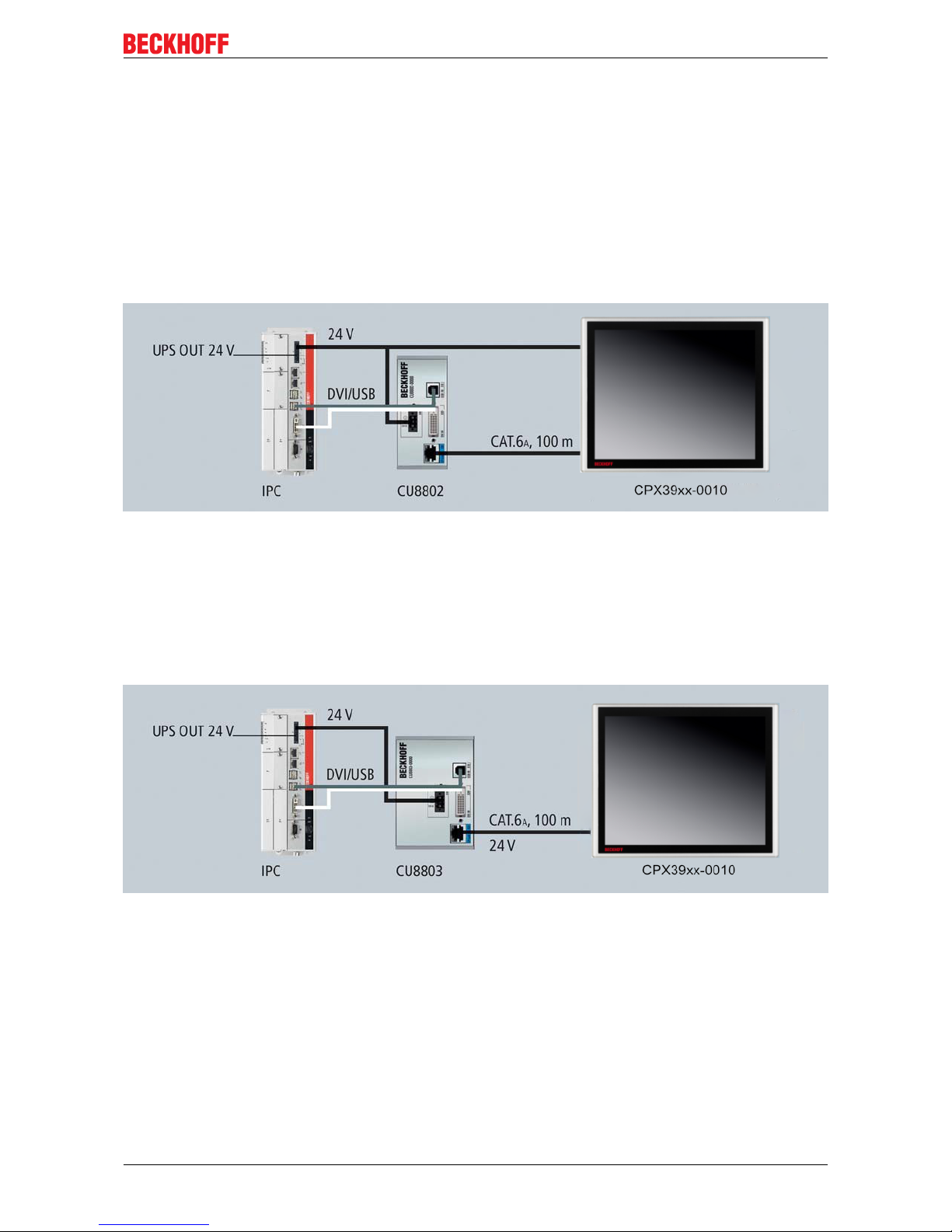
4.3.1.1 CP-Link 4 - The Two Cable Display Link
The CPX39xx-0010 multi-touch panels can be operated up to 100 m away from the PC. CP-Link 4 transfers
DVI and USB together via a CAT.6A cable. The CU8802 CP-Link 4 transmitter box is connected to the PC
via DVI and USB.
Fig.4: CP-Link 4-Two cable Display link via the CU8802 transmitter box
4.3.1.2 CP-Link 4 - The One Cable Display Link
The power supply for the Control Panel can also be provided via CP-Link 4. The CU8803 CP-Link 4
transmitter box is used instead of the CU8802. The Control Panel remains unchanged. The CU8803 sender
box provides power to the Control Panel via the CAT.6A cable, which also transfers DVI and USB. The
power supply socket of the panel is not used.
Fig.5: CP-Link 4-One cable display Link via the CU8803 transmitter box
Page 20

Product overview
CPX39xx-001020 Version: 0.1
4.4 Description of the interfaces
No. Interface
1 CP-Link4 (X102)
2 Power supply (X101)
3 Ground
Also see about this
2 Ground [}21]
4.4.1 Power supply (X101)
Conductive cross-section
The connector is specified for 7.5 A and can lift conductive cross-sections of 1.5 mm2.
The power supply for the Control Panel is established via the 4-pole M12 socket (X101). The protection class
of the circuit plug-in connector accords to the IP65-standard.
X101
SG 4-pole M12 built-in-PCB-sold. IP67 BINDER (BINDER 09-3431-90-04 prod. 763
M12X1)
Table2: Power supply (X101), pin assignment.
Pin Function Pin Function
1 24V DC 3 GND
2 GND 4 24V DC
If using the CP-Link 4- One Cable Display Link technology, the circular plug-in connector is covered with the
provided cap.
Page 21

Product overview
CPX39xx-0010 21Version: 0.1
4.4.2 CP-Link 4 Input (X102)
X102
SG 8-pole M12 built-in-IP67 METZ connect CAT6Ads
The Control Panel is connected with the transmitter box CU8802/ CU8803 via the CP-Link 4 Input (X102).
Pin Signal Pin Signal
1 CP-Link 4_0P 5 CP-Link 4_3P
2 CP-Link 4_0N 6 CP-Link 4_3N
3 CP-Link 4_1P 7 CP-Link 4_2N
4 CP-Link 4_1N 8 CP-Link 4_2P
4.4.3 Ground
Malfunction possible with missing ground connection
A proper ground connection of the device is absolutely necessary for the correct function of the
touchscreen.
The Control Panel is grounded via the screw connection (Ground).
A wire cross section of min. 4 mm2 is required.
Page 22

Mounting and wiring
CPX39xx-001022 Version: 0.1
5 Mounting and wiring
5.1 Mounting
The Control Panel CPX39xx is designed for industrial application in machine and plant engineering. The
Control Panel is intended for mounting arm installation either via 100 x 100 mm mounting interface. The
ambient conditions specified for operation must be observed (see chapter: Technical Data [}33] ).
Permitted mounting position
The Control Panel may only be mounted horizontally.
5.1.1 Preparation of the Panel PC
Please note the following points during installation of the Control Panel:
• Position the Control Panel in such a way that reflections on the screen are avoided as far as possible.
• Use the position of the screen as a guide for the correct installation height; it should be optimally visible
for the user at all times.
• The Control Panel should not be exposed to direct sunlight.
NOTICE
Avoid extreme environmental conditions
Extreme environmental conditions should be avoided as far as possible. Protect the Control Panel from
dust, moisture and heat.
Earthing measures
Earthing connections dissipate interference from external power supply cables, signal cables or cables to
peripheral equipment. Establish a low-impedance connection from the earthing point on the Control Panel
housing to the central earthing point on the control cabinet wall, in which the Control Panel is being installed.
Page 23

Mounting and wiring
CPX39xx-0010 23Version: 0.1
Malfunction possible with missing ground connection
A proper ground connection of the device is absolutely necessary for the correct function of the
touchscreen.
Page 24

Mounting and wiring
CPX39xx-001024 Version: 0.1
5.2 Wiring
5.2.1 Preparation and protective earthing
CAUTION
The mains plug must be disconnected
Please read the documentation for the external devices prior to connecting them!
During thunderstorms, plug connector must neither be inserted nor removed!
When disconnecting a plug connector, always handle it at the plug. Do not pull the cable!
CAUTION
CU8803-0000 disconnect power supply
If using the CP-Link 4 – One Cable Display Link, the 24V power supply of the CP-Link 4
transmitter box must be switched off before disconnecting the CP-Link 4 output connection.
Connecting cables
The connections are located at the back of the Control Panel and are documented in the chapter Interfaces.
When connecting cables to the Control Panel, please adhere to the following order:
• Disconnect the Control Panel from the power supply.
• Connect all cables at the Control Panel and at the devices to be connected.
• Ensure that all screw connections between connectors and sockets are tight!
• Reconnect all devices to the power supply.
Protective Earthing
Malfunction possible with missing ground connection
A proper ground connection of the device is absolutely necessary for the correct function of the
touchscreen.
The low resistance protective earthing connection of the Panel PC is established via the screw connection,
which is located in the connection area.
A wire cross-section of min. 4 mm2 is required.
Page 25

Mounting and wiring
CPX39xx-0010 25Version: 0.1
5.2.2 Connecting
NOTICE
Use the correct fuse
The power supply must be protected with maximum 4 A.
Cable Cross Sections
For the connection of the power supply, wiring with a cable-cross-section of 0.5 … 1.5 mm² must be used.
With bigger distances between voltage source and Control Panel, you take the voltage drop as a function of
the cable-cross-section as well as voltage fluctuations of your distribution voltage into account, so that is
secured that the voltage doesn't fall under 22 V at the power supply.
Check voltage rating and connect
Fitted with the 24 VDC power supply unit:
1. Check that the external power supply is providing the correct voltage.
2. Insert the power supply cable that you have assembled into the Control Panel power supply socket.
Then connect it to your external 24 V power supply.
Page 26
Mounting and wiring
CPX39xx-001026 Version: 0.1
5.2.3 Fitting the power supply
Page 27
Operation
CPX39xx-0010 27Version: 0.1
6 Operation
6.1 Switching the Control Panel on and off
Switching on
The Control Panel does not have its own mains power switch. As soon as the power supply is switched on
the Control Panel is activated.
Shutting down and switching off
Control software such as is typically used on Industrial PCs permits various users to be given different rights.
A user who may not close software may also not switch the Industrial PC off, since data can be lost from the
storage medium by switching off while software is running.
WARNING
First shut down, then switch off!
If the Industrial PC is switched off as the software is writing a file to the storage medium,
the file will be destroyed. Control software typically writes something to the storage medium
every few seconds, so that the probability of causing damage by switching off while the
software is running is very high.
WARNING
Switch off power supply
When you have shut down the Industrial PC, you have to switch off power supply for at
least 10 seconds before rebooting the system.
After resetting power supply the Industrial PC will start booting automatically.
6.2 Touch screen
The operation of the Control Panel occurs via the Touch Screen.
WARNING
Risk of damaging the Touch Screen
The touch screen may only be actuated by finger tips or with the touch screen pen. The operator may wear gloves but there must be no hard particles such as metal shavings, glass
splinters embedded in the glove.
WARNING
Properly installation of the system and the multi-touch device
Capacitive Touch Screens use the functional principle of capacitive alternation of the electrical field. Strong electrical fields can influence the functionality of the multi-touch devices.
To ensure the correct function of the Touch Screen take care of a standardized installation
of all parts of the system and an EMC-environment conforming to standards.
Page 28

Operation
CPX39xx-001028 Version: 0.1
6.3 Servicing and maintenance
Cleaning
WARNING
Disconnect power supply
Switch off the device and all connected devices, and disconnect the device from the power supply.
The device can be cleaned with a soft, damp cleaning cloth. Do not use any aggressive cleaning materials,
thinners, scouring material or hard objects that could cause scratches.
Maintenance
The Control Panel is maintenance-free. Do not open the Control Panel. For hardware problems, please
contact the Beckhoff Service
6.4 Emergency procedures
In case of fire, the Control Panel should be extinguished with powder or nitrogen.
6.5 Shutting down
Disposal
Observe national electronics scrap regulations
Observe the national electronics scrap regulations when disposing of the device.
In order to dispose of the device, it must be removed and fully dismantled:
• Housing components (polycarbonate, polyamide (PA6.6)) are suitable for plastic recycling.
• Metal parts can be sent for metal recycling.
• Electronic parts such as disk drives and circuit boards must be disposed of in accordance with national
electronics scrap regulations.
Page 29
Troubleshooting
CPX39xx-0010 29Version: 0.1
7 Troubleshooting
Pixel errors
Pixel errors in the TFT display are production-caused and represent no complaint- reason!
Anomalies of the Touchscreen
Anomalies of the touchscreen sensor are production-caused and represent no complaint-reason!
Fault Cause Measures
The Control Panel shows no function No power supply to the Control
Panel/ Industrial PC
Cable not connected
Check power supply cable
1. Correctly connect cable
2. Call Beckhoff Service
Computer boots, software starts, but
control does not operate correctly
Cause of the fault is either in the
software or in parts of the plant
outside the Industrial PC
Call the manufacturer of the
machine or the software
Malfunction of the touchscreen Bad or missing ground connection of
the device
Establish ground connection
Bad or missing ground connection of
the user
User must stand on the floor
with ordinary shoes
USB error while TwinCAT access via
USB
Cycle time in TwinCAT is set on 10
ms (standard)
Increase the cycle time up to
50 ms till 80 ms
The Control Panel functions only
partially or only part of the time, e.g.
no or dark picture
Faulty backlight in the display
Defective components in the Control
Panel
Call Beckhoff Service
Call Beckhoff Service
Page 30
Assembly dimensions
CPX39xx-001030 Version: 0.1
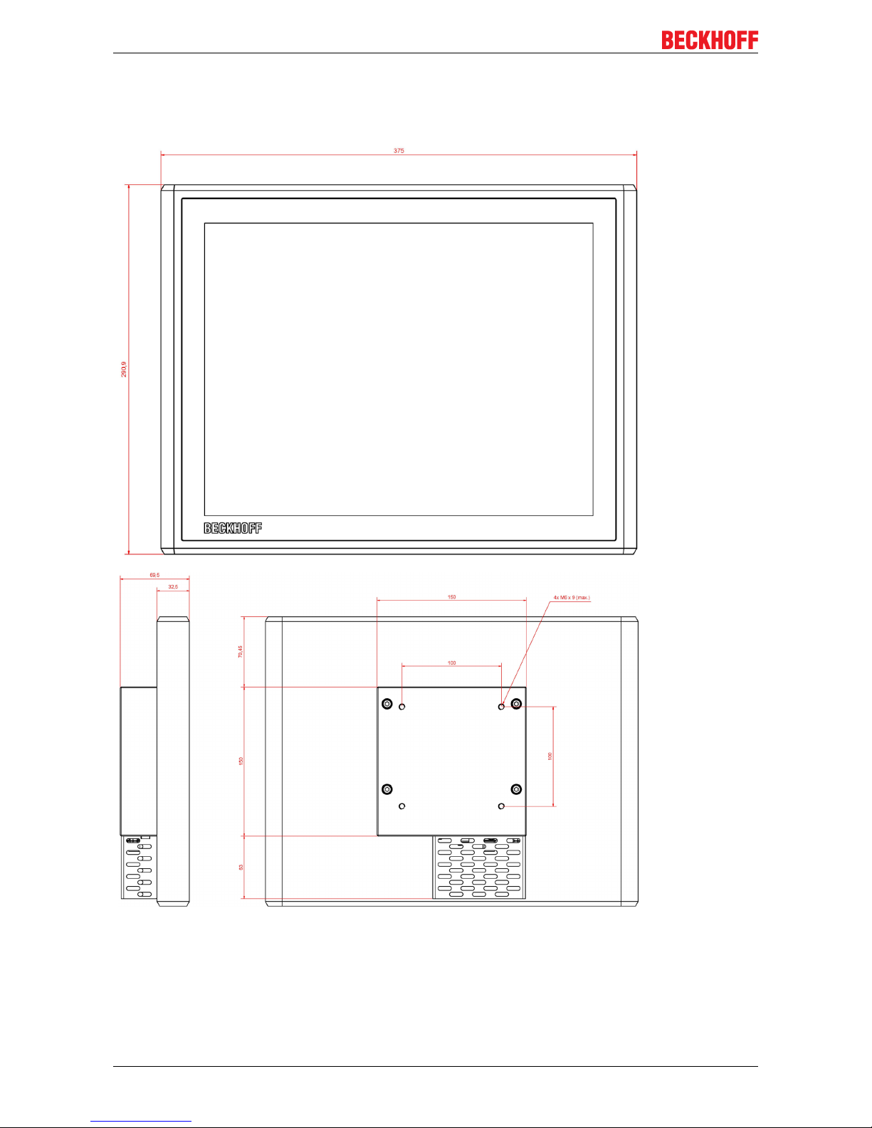
8 Assembly dimensions
CPX3915-0010
Page 31
Assembly dimensions
CPX39xx-0010 31Version: 0.1
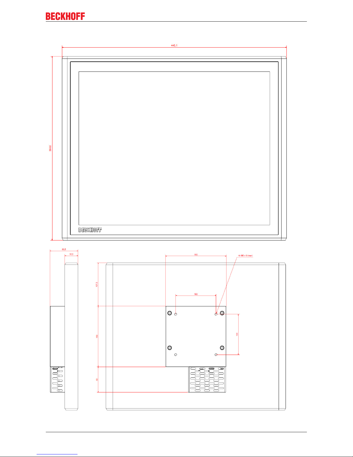
CPX3919-0010
Page 32

Assembly dimensions
CPX39xx-001032 Version: 0.1
CPX3921-0010
Page 33

Technical Data
CPX39xx-0010 33Version: 0.1
9 Technical Data
Product name CPX3915-0010 CPX3919-0010 CPX3921-0010
Dimensions (W x H x D) 375 x 290.9 x
69.5 mm
445.1 x 364.8 x
69.5 mm
549.8 x 330.3 x
69.5 mm
Weight approx. 5.3 kg approx. 7.4 kg approx. 8.0 kg
Supply voltage 24 V DC (22 – 30 V DC)
Power consumption max. 20 W max. 25 W max. 35 W
UL-compliance (in
progress)
• Using a power supply class 2 or
• Fuse protection with 4 A, according to UL 60950.2
chapter 2.5, table 2C
Interfaces CP-Link 4
Power supply
Protection class IP65
Shock resistance
(Sinusoidal vibration)
EN 60068-2-6: 10 bis 58 Hz: 0,035 mm
58 bis 500 Hz 0,5 G (~ 5 m/ s2)
Shock resistance (Shock) EN 60068-2-27: 5 G (~ 50 m/ s2), duration: 30 ms
EMC compatibility Resistance to interference conforms to EN 61000-6-2
EMC compatibility Emission of interference conforms to EN 61000-6-4
Permissible ambient
temperature
Operation: 0°C to +50° Transport/ storage: -20°C to +70°C
Pollution degree 2
Permissible relative
humidity
to 95%, no condensation
Transport and storage The same values for atmospheric humidity and shock
resistance are to be observed during transport and
storage as in operation. Suitable packaging of the Panel
PC can improve the resistance to impact during transport.
Certifications CE
Page 34

Appendix
CPX39xx-001034 Version: 0.1
10 Appendix
10.1 Standards reference for explosive atmospheres
The following standards have been used:
ATEX
Standard Description
EN 60079-0:2012+A11:2013 Explosive atmospheres- Part0: Equipment- General requirements
EN 60079-15:2010 Explosive atmospheres - Part 15: Equipment protection by type of protection
“n”
EN 60079-31:2014 Explosive atmospheres - Part 31: Equipment dust ignition protection by
enclosure "t"
IECEx
Standard Description
IEC 60079-0:2011 Explosive atmospheres- Part0: Equipment- General requirements
IEC 60079-15:2017 Explosive atmospheres – Part 15: Equipment protection by type of protection
“n”
IEC 60079-31:2013 Explosive atmospheres - Part 31: Equipment dust ignition protection by
enclosure "t"
Page 35

Appendix
CPX39xx-0010 35Version: 0.1
10.2 Approvals for USA and Canada
FCC: Federal Communications Commission Radio Frequency Interference
Statement
This equipment has been tested and found to comply with the limits for a Class A digital device, pursuant to
Part 15 of the FCC Rules. These limits are designed to provide reasonable protection against harmful
interference when the equipment is operated in a commercial environment. This equipment generates, uses,
and can radiate radio frequency energy and, if not installed and used in accordance with the instruction
manual, may cause harmful interference to radio communications. Operation of this equipment in a
residential area is likely to cause harmful interference in which case the user will be required to correct the
interference at his own expense.
Technical modifications
Technological changes to the device may cause the loss of the FCC approval.
FCC: Canadian Notice
This equipment does not exceed the Class A limits for radiated emissions as described in the Radio
Interference Regulations of the Canadian Department of Communications.
Page 36

Appendix
CPX39xx-001036 Version: 0.1
10.3 Connection Kits/ Connecting Cables/ Accessories
One 4-pole power supply connector is provided with the Panel PC. Optionally prefabricated connection
cables for the network connection are available.
Accessories for CPX39xx-0010, optional
The following accessories are available:
Connecting cables
Network cable with IP65 connector
CU8802-0000 Transmitter box for CP-Link 4 – The Two Cable Display Link
CP-Link 4 Extender Tx for connecting a Control Panel with CP-Link 4 interface
CP29xx-0010, CP39xx-0010 or CPX39xx-0010
CU8803-0000 Transmitter box for CP-Link 4 – The One Cable Display Link
CP-Link 4 Extender Tx for connecting a Control Panel with CP-Link 4 interface
CP29xx-0010, CP39xx-0010 or CPX39xx-0010
Page 37

Appendix
CPX39xx-0010 37Version: 0.1
Connecting cable for CPX39xx-0010, optional
The following accessories are available:
Accessories Cable for CU880x
C9900-K667 Connecting cable RJ45, Cat.6A, 3 m, one end with IP 65 connector for Control Panel
CP39xx-0010 or CPX39xx-0010
C9900-K652 Connecting cable RJ45, Cat.6A, 5 m, one end with IP 65 connector for Control Panel
CP39xx-0010 or CPX39xx-0010
C9900-K653 Connecting cable RJ45, Cat.6A, 10 m, one end with IP 65 connector for Control Panel
CP39xx-0010 or CPX39xx-0010
C9900-K654 Connecting cable RJ45, Cat.6A, 20 m, one end with IP 65 connector for Control Panel
CP39xx-0010 or CPX39xx-0010
C9900-K655 Connecting cable RJ45, Cat.6A, 30 m, one end with IP 65 connector for Control Panel
CP39xx-0010 or CPX39xx-0010
C9900-K656 Connecting cable RJ45, Cat.6A, 40 m, one end with IP 65 connector for Control Panel
CP39xx-0010 or CPX39xx-0010
C9900-K657 Connecting cable RJ45, Cat.6A, 50 m, one end with IP 65 connector for Control Panel
CP39xx-0010 or CPX39xx-0010
C9900-K658 Connecting cable RJ45, Cat.6A, 60 m, one end with IP 65 connector for Control Panel
CP39xx-0010 or CPX39xx-0010
C9900-K659 Connecting cable RJ45, Cat.6A, 70 m, one end with IP 65 connector for Control Panel
CP39xx-0010 or CPX39xx-0010
C9900-K660 Connecting cable RJ45, Cat.6A, 80 m, one end with IP 65 connector for Control Panel
CP39xx-0010 or CPX39xx-0010
C9900-K661 Connecting cable RJ45, Cat.6A, 90 m, one end with IP 65 connector for Control Panel
CP39xx-0010 or CPX39xx-0010
C9900-K662 Connecting cable RJ45, Cat.6A, 100 m, one end with IP 65 connector for Control Panel
CP39xx-0010 or CPX39xx-0010
C9900-K724 Connecting cable RJ45, Cat.6A, 3 m, one end with IP 65 connector for Control Panel
CP39xx-0010 or CPX39xx-0010 suitable as trailing cable
C9900-K704 Connecting cable RJ45, Cat.6A, 5 m, one end with IP 65 connector for Control Panel
CP39xx-0010 or CPX39xx-0010 suitable as trailing cable
C9900-K705 Connecting cable RJ45, Cat.6A, 10 m, one end with IP 65 connector for Control Panel
CP39xx-0010 or CPX39xx-0010 suitable as trailing cable
C9900-K706 Connecting cable RJ45, Cat.6A, 20 m, one end with IP 65 connector for Control Panel
CP39xx-0010 or CPX39xx-0010 suitable as trailing cable
C9900-K707 Connecting cable RJ45, Cat.6A, 30 m, one end with IP 65 connector for Control Panel
CP39xx-0010 or CPX39xx-0010 suitable as trailing cable
C9900-K708 Connecting cable RJ45, Cat.6A, 40 m, one end with IP 65 connector for Control Panel
CP39xx-0010 or CPX39xx-0010 suitable as trailing cable
C9900-K709 Connecting cable RJ45, Cat.6A, 50 m, one end with IP 65 connector for Control Panel
CP39xx-0010 or CPX39xx-0010 suitable as trailing cable
C9900-K710 Connecting cable RJ45, Cat.6A, 60 m, one end with IP 65 connector for Control Panel
CP39xx-0010 or CPX39xx-0010 suitable as trailing cable
C9900-K711 Connecting cable RJ45, Cat.6A, 70 m, one end with IP 65 connector for Control Panel
CP39xx-0010 or CPX39xx-0010 suitable as trailing cable
C9900-K712 Connecting cable RJ45, Cat.6A, 80 m, one end with IP 65 connector for Control Panel
CP39xx-0010 or CPX39xx-0010 suitable as trailing cable
Page 38

Appendix
CPX39xx-001038 Version: 0.1
10.4 Support and Service
Beckhoff and their partners around the world offer comprehensive support and service, making available fast
and competent assistance with all questions related to Beckhoff products and system solutions.
Beckhoff's branch offices and representatives
Please contact your Beckhoff branch office or representative for local support and service on Beckhoff
products!
The addresses of Beckhoff's branch offices and representatives round the world can be found on her internet
pages:
http://www.beckhoff.com
You will also find further documentation for Beckhoff components there.
Beckhoff Headquarters
Beckhoff Automation GmbH & Co. KG
Huelshorstweg 20
33415 Verl
Germany
Phone: +49(0)5246/963-0
Fax: +49(0)5246/963-198
e-mail: info@beckhoff.com
Beckhoff Support
Support offers you comprehensive technical assistance, helping you not only with the application of
individual Beckhoff products, but also with other, wide-ranging services:
• support
• design, programming and commissioning of complex automation systems
• and extensive training program for Beckhoff system components
Hotline: +49(0)5246/963-157
Fax: +49(0)5246/963-9157
e-mail: support@beckhoff.com
Beckhoff Service
The Beckhoff Service Center supports you in all matters of after-sales service:
• on-site service
• repair service
• spare parts service
• hotline service
Hotline: +49(0)5246/963-460
Fax: +49(0)5246/963-479
e-mail: service@beckhoff.com
 Loading...