

Page 1

Operation Manual
Stepper motor AS2000
1.0
2018-07-10
Version:
Date:
Page 2

Page 3

Table of content
Stepper motor AS2000 3
Version: 1.0
Table of content
1 Foreword ....................................................................................................................................................5
1.1 Notes on the documentation..............................................................................................................5
1.2 Documentation Issue Status..............................................................................................................6
1.3 Appropriate use .................................................................................................................................6
2 Guidelines and Standards ........................................................................................................................7
2.1 EU conformity ....................................................................................................................................7
3 For your safety...........................................................................................................................................8
3.1 Staff qualification ...............................................................................................................................8
3.2 Description of symbols ......................................................................................................................9
3.3 Notes on the AS2000 stepper motor ...............................................................................................10
4 Handling ...................................................................................................................................................11
4.1 Transport .........................................................................................................................................11
4.2 Packaging........................................................................................................................................11
4.3 Storage ............................................................................................................................................11
4.4 Maintenance / Cleaning...................................................................................................................12
4.5 Disposal...........................................................................................................................................12
5 Product overview.....................................................................................................................................13
5.1 AS2000 scope of delivery................................................................................................................13
5.2 AS2000 type plate ...........................................................................................................................13
5.3 AS2000 type key .............................................................................................................................14
6 Technical description..............................................................................................................................15
6.1 Design of the motors .......................................................................................................................15
6.2 General technical data.....................................................................................................................16
6.3 Standard features ............................................................................................................................16
6.3.1 Style................................................................................................................................. 16
6.3.2 Shaft end, A-side ............................................................................................................. 17
6.3.3 Flange.............................................................................................................................. 17
6.3.4 Connection technology .................................................................................................... 17
6.3.5 Feedback system............................................................................................................. 17
6.4 Transport, assembly and disassembly ............................................................................................17
7 Mechanical installation ...........................................................................................................................18
7.1 Important notes................................................................................................................................18
7.2 Installing the stepper motor .............................................................................................................19
8 Electrical installation...............................................................................................................................20
8.1 Important notes................................................................................................................................20
8.2 Connection of motors with preassembled cables ............................................................................21
8.3 Electrical components .....................................................................................................................22
8.3.1 Motor connector............................................................................................................... 22
8.3.2 Encoder connector........................................................................................................... 22
8.4 Connection diagram KL2531 ...........................................................................................................23
8.5 Connection diagram EL7031 ...........................................................................................................24
8.6 Connection diagram EL7037 ...........................................................................................................25
Page 4

Table of content
Stepper motor AS20004
Version: 1.0
8.7 Connection diagram EL7041-1000..................................................................................................26
8.8 Connection diagram EL7047 ...........................................................................................................27
8.9 Connection diagram EP7041...........................................................................................................28
8.10 Connection diagram EPP7041 ........................................................................................................29
8.11 Connection diagram EJ7047 ...........................................................................................................30
9 Commissioning........................................................................................................................................31
9.1 Important notes................................................................................................................................31
9.2 Guide for commissioning .................................................................................................................31
9.3 Troubleshooting...............................................................................................................................32
10 Technical data..........................................................................................................................................33
10.1 Step mode and limit speeds ............................................................................................................33
10.2 AS202x ............................................................................................................................................34
10.2.1 Dimensional drawing AS202x with encoder .................................................................... 35
10.3 AS204x ............................................................................................................................................36
10.3.1 Dimensional drawing AS204x with encoder .................................................................... 37
Page 5

Foreword
Stepper motor AS2000 5
Version: 1.0
1 Foreword
1.1 Notes on the documentation
This description is only intended for the use of trained specialists in control and automation engineering who
are familiar with the applicable national standards.
It is essential that the documentation and the following notes and explanations are followed when installing
and commissioning the components.
It is the duty of the technical personnel to use the documentation published at the respective time of each
installation and commissioning.
The responsible staff must ensure that the application or use of the products described satisfy all the
requirements for safety, including all the relevant laws, regulations, guidelines and standards.
Disclaimer
The documentation has been prepared with care. The products described are, however, constantly under
development.
We reserve the right to revise and change the documentation at any time and without prior announcement.
No claims for the modification of products that have already been supplied may be made on the basis of the
data, diagrams and descriptions in this documentation.
Trademarks
Beckhoff®, TwinCAT®, EtherCAT®, Safety over EtherCAT®, TwinSAFE®, XFC® and XTS® are registered
trademarks of and licensed by Beckhoff Automation GmbH.
Other designations used in this publication may be trademarks whose use by third parties for their own
purposes could violate the rights of the owners.
Patent Pending
The EtherCAT Technology is covered, including but not limited to the following patent applications and
patents:
EP1590927, EP1789857, DE102004044764, DE102007017835
with corresponding applications or registrations in various other countries.
The TwinCAT Technology is covered, including but not limited to the following patent applications and
patents:
EP0851348, US6167425 with corresponding applications or registrations in various other countries.
EtherCAT® is registered trademark and patented technology, licensed by Beckhoff Automation GmbH,
Germany
Copyright
© Beckhoff Automation GmbH & Co. KG, Germany.
The reproduction, distribution and utilization of this document as well as the communication of its contents to
others without express authorization are prohibited.
Offenders will be held liable for the payment of damages. All rights reserved in the event of the grant of a
patent, utility model or design.
Page 6
Foreword
Stepper motor AS20006
Version: 1.0
1.2 Documentation Issue Status
Origin of the document
This documentation was originally written in German. All other languages are derived from the German
original.
Product features
Only the product features specified in the current user documentation are valid. Further information given on
the product pages of the Beckhoff homepage, in emails or in other publications is not authoritative.
Issue Comment
1.0 First edition
1.3 Appropriate use
Beckhoff stepper motors from the AS2000 series are specially designed for use as actuators in handling
devices, textile machines, machine tools, packaging machines and similar machines. They are exclusively
intended to be operated by stepper motor output stages from Beckhoff Automation GmbH & Co. KG using
speed and/or position control.
CAUTION
Danger for persons, the environment or equipment
The motors are operated in the drive system in conjunction with Beckhoff stepper motor output stages.
Please observe the entire documentation which consists of:
• AS2000 documentation (this manual)
• Complete documentation (online and paper) for Beckhoff stepper motor output stages available at
www.beckhoff.com
.
• Complete machine documentation (provided by the machine manufacturer)
WARNING
Caution - Risk of injury!
Basically, electronic devices are not fail-safe. The machine manufacturer is responsible for
ensuring that the connected motors and the machine are brought into a safe state in the
event of a fault in the drive system.
Special safety instructions for the AS2000!
It is essential to follow the Notes on the AS2000 stepper motor when installing and commissioning
the components. Read this chapter carefully, attentively and completely!
The stepper motors from the AS2000 series are designed for installation as components in electrical
systems or machines and may be operated only as integrated system or machine components.
The motors may only be operated under the ambient conditions defined in this documentation.
Improper use
Beckhoff stepper motors from the AS2000 series are not suitable for use in the following areas:
• in ATEX zones without a suitable housing
• in areas with aggressive environments (e.g. aggressive gases or chemicals)
Page 7
Guidelines and Standards
Stepper motor AS2000 7
Version: 1.0
2 Guidelines and Standards
CAUTION
Danger for persons, the environment or equipment
Stepper motors of the AS2000 series are not products as defined by the EC Machinery Directive. Operation of the stepper motors in machines or systems is only permitted once the machine or system manufacturer has provided evidence of CE conformity of the complete machine or system.
2.1 EU conformity
Provision of EU Declaration of Conformity:
Beckhoff Automation GmbH & Co. KG will be glad to provide you with EU declarations of conformity
and manufacturer's declarations for all products upon request to info@beckhoff.com.
Page 8

For your safety
Stepper motor AS20008
Version: 1.0
3 For your safety
Read the section on safety and heed the notices to protect yourself against personal injury and material
damages.
Liability limitations
The entire components of the Beckhoff AS2000 stepper motors are delivered in certain hardware and
software configurations according to the application requirements. Unauthorized modifications to the
hardware and/or software configurations other than those described in the documentation are not permitted,
and nullify the liability of Beckhoff Automation GmbH & Co. KG.
In addition, the following actions are excluded from the liability of Beckhoff Automation GmbH & Co.
KG:
• Failure to comply with this documentation
• Improper use
• Use of untrained personnel
• Use of unauthorized spare parts
3.1 Staff qualification
All depicted work to be done on the Beckhoff software and hardware, and in particular on the AS2000
stepper motor, may be carried out only by technical personnel with knowledge of control and automation
technology.
The technical personnel must have knowledge of drive technology and electrical systems and must also
know how to work safely on electrical equipment and machines.
This also includes:
• production planning and
• securing of the working environment (e.g. securing the control cabinet against being switched on
again).
The technical personnel must be familiar with the current and necessary standards and directives for the
automation and drive environment.
Page 9

For your safety
Stepper motor AS2000 9
Version: 1.0
3.2 Description of symbols
In this documentation the following symbols are used with an accompanying safety instruction or note. The
safety instructions must be read carefully and followed without fail!
Symbols that warn of personal injury:
DANGER
Serious risk of injury!
This is an extremely dangerous situation. Disregarding the safety notice will lead to serious permanent injuries or even death.
WARNING
Risk of injury!
This is a dangerous situation. Disregarding the safety notice may lead to serious injuries.
CAUTION
Personal injuries!
This is a dangerous situation. Disregarding the safety notice may lead to minor injuries.
Symbols that warn of damage to property or equipment:
NOTE
Warning of damage to property or the environment!
This notice indicates disturbances in the operational procedure that could damage the product or the environment.
Symbols indicating further information or tips:
Tip or pointer!
This notice provides important information that will be of assistance in dealing with the product or
software. There is no immediate danger to product, people or environment.
UL note!
This symbol indicates important information regarding UL certification.
Page 10
For your safety
Stepper motor AS200010
Version: 1.0
3.3 Notes on the AS2000 stepper motor
The notes are intended to avert danger and to provide instructions on the handling of the AS2000 stepper
motors. They must be followed during installation, commissioning, production, troubleshooting, maintenance
and trial or test assemblies.
The stepper motors from the AS2000 series cannot run as stand-alone devices. They must always be
installed in a machine or system. After installation the additional documentation and safety instructions
provided by the machine manufacturer must be read and followed.
WARNING
Serious burns due to hot surfaces on the devices!
The surface temperature of the devices can reach ≥ 100 °C during operation of the system. There is an
acute risk of sustaining burns to parts of the body and limbs.
Take the following measures to avert danger:
• Do not touch any components (housing, etc.) shortly after or during operation.
• Wait until all components have cooled sufficiently. At least 15 minutes.
• Check the surface temperature with a thermometer.
• DO NOT wear work gloves with a rubber coating. These can fuse with the skin on account of the high
temperature and cause serious injuries.
Notes on the operation of the AS2000 stepper motors:
• Please read this manual carefully before using the stepper motors. Notify the responsible sales
office immediately if any passages are not understandable. Refrain from working on the servo
drive.
NOTE
Damage to the environment or devices
• During installation it is essential to ensure that the specified ventilation clearances and climatic conditions are adhered to. Further information can be found in the "Technical data" and "Mechanical installation" sections.
• The stepper motor may only be put into operation when it has been established that the machine or
plant conforms to the latest edition of the EU Machinery Directive.
Page 11
Handling
Stepper motor AS2000 11
Version: 1.0
4 Handling
4.1 Transport
• Climate category: 2K3 according to EN 60721
• Transport temperature: -20 °C to +65 °C, max. fluctuation 20 K/hour
• Transport humidity: relative humidity 5% - 95%, non-condensing
• The stepper motor may only be transported by qualified personnel and in the manufacturer's original
recyclable packaging.
• Avoid hard impacts, particularly at the shaft end.
• If the packaging is damaged, check the motor for visible damage. Inform the transport company and, if
necessary, the manufacturer.
4.2 Packaging
• Cardboard packaging
Motor without installed gear unit
Motor type Max. stacking height
AS2021 5
AS2022 5
AS2023 5
AS2041 5
AS2042 5
AS2043 5
Motor with installed gear unit
Motor and gear type Max. stacking height
AS2021 with AG2250-+PLE60 / WPLE60 3
AS2022 with AG2250-+PLE60 / WPLE60 3
AS2023 with AG2250-+PLE60 / WPLE60 2
AS2041 with AG2250-+PLE80 / WPLE80 2
AS2042 with AG2250-+PLE80 / WPLE80 2
AS2043 with AG2250-+PLE80 / WPLE80 2
4.3 Storage
• Climate category: 2K3 according to EN 60721
• Storage temperature: -20 °C to +65 °C, max. fluctuation 20 K/hour
• Air humidity: relative humidity 5% - 95%, non-condensing
• Max. stacking height: see table Packaging
• Storage time: without limitation
• Store only in the manufacturer’s original recyclable packaging.
Page 12
Handling
Stepper motor AS200012
Version: 1.0
4.4 Maintenance / Cleaning
• Maintenance and cleaning only by qualified personnel.
• The ball bearings have a grease filling. The actual life of the bearings depends on various factors,
including the radial load, shear load, operating temperature and motor speed.
• Check the motor for bearing noise every 2,500 operating hours or once per year. If any noises are
heard, stop the operation of the motor. The bearings must be replaced.
• Opening the motor invalidates the warranty.
• Clean the housing with isopropanol or similar.
NOTE
Destruction of the stepper motor
Never immerse or spray the stepper motor.
4.5 Disposal
In accordance with the WEEE 2012/96/EG Directives we take old devices and accessories back for
professional disposal, provided the transport costs are taken over by the sender.
Send the devices with the note “For disposal” to:
Beckhoff Automation GmbH & Co. KG
Huelshorstweg 20
D-33415 Verl
Page 13

Product overview
Stepper motor AS2000 13
Version: 1.0
5 Product overview
5.1 AS2000 scope of delivery
Please check that the delivery includes the following items:
• Motor from the AS2000 series
• Online documentation at www.beckhoff.de
Scope of supply
The M12 mating connectors are not included in the scope of delivery.
The following accessories are available on request:
• Preassembled motor and feedback cable
• Planetary gear units from the AG2250-+PLE60 series for flange sizes N2 (NEMA 23)
• Planetary gear units from the AG2250-+PLE80 series for flange sizes N3 (NEMA 34)
• Planetary gear units from the AG2250-+WPLE60 series for flange sizes N2 (NEMA 23)
• Planetary gear units from the AG2250-+WPLE80 series for flange sizes N3 (NEMA 34)
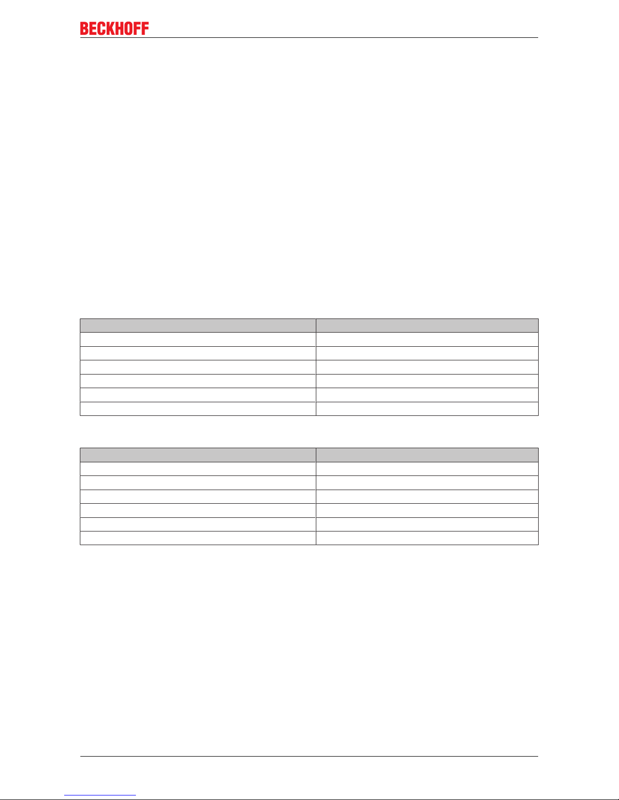
5.2 AS2000 type plate
Item no. Name
1 Article description
2 Standstill torque
3 Rated supply voltage
4 Product identification code
5 UL certification
6 EAC certification
7 CE certification
8 Protection class
9 Standstill current
Page 14

Product overview
Stepper motor AS200014
Version: 1.0
5.3 AS2000 type key
Page 15

Technical description
Stepper motor AS2000 15
Version: 1.0
6 Technical description
6.1 Design of the motors
Beckhoff stepper motors from the AS2000 series are highly scalable. They are characterized by a high
holding torque and are adapted to international standards in the flange sizes N2 (NEMA23) and N3
(NEMA34). The step angle of 1.8° significantly reduces the performance gap to the AM8000 high
performance servo motor. The performance range extends from a standstill torque of 0.8 Nm to 8 Nm.
The new design of the AS2000 series is tailored more strongly to industrial requirements. Due to the
protection class IP54 the motors are resistant to splash water, touching and dust. The standardized highpower M12 connecting plugs integrated in the stepper motor enable the simple cabling of power and
encoder. On account of the torsionally rigid encoder (1024 inc/rev), the motor is usable for the closed loop
control for stepper motors supported by Beckhoff Automation. Resonances as well as the development of
heat and noise are considerable reduced by means of field-oriented control.
All motors from the AS2000 series are to be put into operation with Beckhoff stepper motor terminals and
modules. For further details, please refer to the chapter: "Electrical installation [
}20]".
The stepper motors are available with a smooth shaft or feather key groove (N3 only). Shielded motor and
encoder cables are also available in suitable lengths. Low-backlash planetary gear units from the AG2250
series, incremental encoders and elastic couplings are available for simple mounting on machines.
Beckhoff stepper motors are used as actuators or auxiliary axes in machine construction and automation
applications.
Page 16

Technical description
Stepper motor AS200016
Version: 1.0
6.2 General technical data
Technical data Value [symbol and unit]
Insulation class Class F according to IEC60085
Temperature change at rated current Max. 100 K
Insulation resistance ≥ 100 MΩ
Permissible ambient temperature (operation) -10°C to +50°C
Permissible ambient temperature (transport) -20 °C to +65 °C
Permissible air humidity 20% to 90%, non-condensing
Permissible level of contamination Contamination level 2 according to EN60204/
EN50178
Corrosion protection Under extreme operating conditions, special
measures must be agreed with the manufacturer, and
implemented by the user.
Resolution 1.8°/200 full steps
Rated supply voltage 24…48 V
DC
Coating/surface matt black paint, RAL 9005
Service life L
10h
= 30,000 operating hours of the ball bearing
Permissible operating altitude Up to 1000 m above sea level
Max. cable length 10 m
Special operating conditions The applicability of the Beckhoff AS2000 stepper
motor is to be determined for each individual case.
Application in harsh operating or environmental
conditions requires coordination between
manufacturer and user.
Correct installation position Horizontal or vertical
Ventilation Ensure adequate ventilation of the motors.
Protection class (doesn’t apply to shaft bushing) IP54
6.3 Standard features
6.3.1 Style
The AS20xx stepper motors are flange mounted in accordance with the mounting positions IM B5, IM V1 and
IM V3.
The permitted mounting positions are specified in the technical data.
NOTE
Destruction of the motors
Mounting positions IM V1 and IM V3 may result in liquid entering the motor and associated damage.
Page 17

Technical description
Stepper motor AS2000 17
Version: 1.0
6.3.2 Shaft end, A-side
The force is transmitted by means of a claw coupling (friction-locked/backlash-free), via the cylindrical shaft
end A or optionally as a friction-locked connection by means of feather key groove according to DIN6885 P1
(AS204x only).
Radial force
If the motors drive via pinions or toothed belts, then high radial forces will occur.
Axial force
Axial forces are applied when mounting pinions or pulleys on the shaft.
Coupling
Double-coned collets, possibly in association with metal bellows couplings, have proven themselves as
excellent, zero backlash coupling elements.
6.3.3 Flange
Flange dimensions according to NEMA 23 (AS202x) and NEMA 34 (AS204x), fit j6, accuracy according to
DIN 60034-7
Tolerance class: N
6.3.4 Connection technology
AS20xx:
The motors are equipped with M12 high-power connecting plugs (4-pin) for the power supply and M12
connecting plugs (5-pin) for the feedback signals (encoder only).
The mating connectors are not included in the scope of supply. Ready-made extension cables in different
lengths are available as accessories.
6.3.5 Feedback system
Feedback system Resolution Comment
Incremental encoders 1,024 increments AS20xx
6.4 Transport, assembly and disassembly
CAUTION
Personal injuries!
Protective clothing, protective gloves and safety boots must be worn at all times during transport, assembly
and disassembly. Do not step under suspended motors.
The motors of the AS2000 series can be moved without auxiliary equipment.
Page 18

Mechanical installation
Stepper motor AS200018
Version: 1.0
7 Mechanical installation
7.1 Important notes
NOTE
Destruction of the motors
• Protect the motors from unacceptable stresses. Take care, especially during transport and handling,
that components are not bent and that insulation clearances are not altered.
• The site must be free of conductive and aggressive material. For V1/V3-mounting (shaft end upwards),
make sure that no liquids can enter the bearings. If an encapsulated assembly is required, please consult our applications department beforehand.
• Ensure unhindered ventilation of the motors and observe the permissible ambient and flange temperatures. For ambient temperatures above 50 °C please consult our applications department beforehand.
• Stepper motors are precision devices. The flange and shaft are especially vulnerable during storage
and assembly. It is important to use the locking thread which is provided to tighten up couplings, gear
wheels or pulleys and warm up the drive components, where possible. Blows or the use of force will
lead to damage to the ball bearings, the shaft, the holding brake and the feedback system.
• Wherever possible, use only backlash-free, frictionally-locking collets or couplings. Ensure correct alignment of the couplings. A displacement will cause unacceptable vibration and the destruction of the ball
bearings and the coupling.
• For toothed belts, it is vital to observe the permissible radial forces. An excessive radial load on the
shaft will significantly shorten the service life of the motor.
• Avoid axial loads on the motor shaft, as far as possible. Axial loading significantly shortens the service
life of the motor and can result in malfunction of the brake.
• In any case, avoid creating a mechanically constrained motor shaft mounting by using a rigid coupling
with additional external bearings (e.g. in a gearbox).
• Check compliance with the permitted radial and axial loads FR and FA. When using a toothed belt drive,
the minimum permitted diameter of the pinion follows from the equation:
Page 19

Mechanical installation
Stepper motor AS2000 19
Version: 1.0
7.2 Installing the stepper motor
When assembling, make sure that the fastening of the stepper motor is not mechanically overdetermined.
Avoid warping, particularly when assembling the shaft.
Page 20

Electrical installation
Stepper motor AS200020
Version: 1.0
8 Electrical installation
8.1 Important notes
DANGER
Serious risk of injury through electric shock!
• Only staff qualified and trained in electrical engineering are allowed to wire up the motor.
• Check the assignment of the stepper motor output stage and the motor. Compare the rated voltage and
the rated current of the devices.
• Always make sure that the motors are de-energized during assembly and wiring, i.e. no operating voltage may be switched on for any piece of equipment which is to be connected. Ensure that the control
cabinet remains turned off (barrier, warning signs etc.). The individual voltages will only be turned on
again during commissioning.
• Control and power leads may be live, even if the motor is not running.
NOTE
Smooth operation
• Ensure that the motor is grounded properly. See below for further information regarding EMC shielding
and earthing. Earth the mounting plate and motor housing. Information about the connection method
can be found in Section 7.3.4
• Use only cables approved by Beckhoff for the operation of the
AS2000 stepper motors.
• Wiring:
ð Connecting the feedback cable (optional)
ð Connect the motor cable
ð Shielding at both ends (shield terminal or EMC plug)
NOTE
HF interference
• The ground symbol, which you will find in the circuit diagrams, indicates that you must provide an electrical connection, with as large a surface area as possible, between the unit indicated and the mounting
plate in the control cabinet. This connection is to suppress HF interference and must not be confused
with the PE (protective earth) symbol (protective measure according to EN 60204).
Page 21

Electrical installation
Stepper motor AS2000 21
Version: 1.0
8.2 Connection of motors with preassembled cables
Beckhoff offers preassembled motor and feedback cables for safe, faster and flawless installation of the
motors. Beckhoff cables have been tested with regard to the materials, shielding and connection method
used. They ensure proper functioning and compliance with statutory regulations such as EMC, UL etc. The
use of other cables may lead to unexpected interference and invalidate the warranty.
• Carry out the wiring in accordance with the valid standards and regulations.
• Only use our preassembled shielded cables for the power and feedback connections.
• The shielding should match the specifications in sections 8.4 to 8.10. Incorrectly installed shielding
inevitably leads to EMC interference.
Page 22

Electrical installation
Stepper motor AS200022
Version: 1.0
8.3 Electrical components
8.3.1 Motor connector
M12 high-power connecting plug (4-pin) for power supply.
Contact Signal Round connector – 4-pin
1 Phase A1
2 Phase A2
3 Phase B1
4 Phase B2
8.3.2 Encoder connector
M12 connecting plug (5-pin) for feedback cable.
Pin Signal Round connector – 5-pin
1 0 V
2 + Ub
3 Track A
4 Track B
5 Track 0
Page 23

Electrical installation
Stepper motor AS2000 23
Version: 1.0
8.4 Connection diagram KL2531
Page 24

Electrical installation
Stepper motor AS200024
Version: 1.0
8.5 Connection diagram EL7031
Page 25

Electrical installation
Stepper motor AS2000 25
Version: 1.0
8.6 Connection diagram EL7037
Page 26

Electrical installation
Stepper motor AS200026
Version: 1.0
8.7 Connection diagram EL7041-1000
Page 27

Electrical installation
Stepper motor AS2000 27
Version: 1.0
8.8 Connection diagram EL7047
Page 28

Electrical installation
Stepper motor AS200028
Version: 1.0
8.9 Connection diagram EP7041
Page 29

Electrical installation
Stepper motor AS2000 29
Version: 1.0
8.10 Connection diagram EPP7041
Page 30

Electrical installation
Stepper motor AS200030
Version: 1.0
8.11 Connection diagram EJ7047
Page 31

Commissioning
Stepper motor AS2000 31
Version: 1.0
9 Commissioning
9.1 Important notes
DANGER
Serious risk of injury!
• Only specialist personnel with extensive knowledge in the areas of electrical engineering / drive technology are allowed to install and commission the equipment.
• The surface temperature of the motor can exceed 100°C in operation. Check (measure) the temperature of the motor. Wait until the motor has cooled down below 40 °C before touching it.
• Make sure that, even if the drive starts to move unintentionally, no danger can result for personnel or
machinery.
NOTE
Overload of the gear unit!
In the case of motor/gear unit combinations, the gear unit may be overloaded in the event of a fault (mechanical blockage of the drivetrain) due to high gear ratios.
To prevent this, make sure that the rated and peak motor torque is limited in the servo drive.
Example:
• Rated / peak motor torque: 1 Nm / 5 Nm
• Rated / peak gear unit torque: 15 Nm / 24 Nm
• Gear ratio: i = 10
• The rated motor torque is not limited. The peak motor torque is limited to 2.4 Nm.
9.2 Guide for commissioning
The procedure for commissioning is described as an example.
A different method may be appropriate or necessary, depending on the application of the equipment.
• Check the assembly and orientation of the motor.
• Check the drive components (coupling, gear unit, pulley) for the correct seating and setting (observe
the permissible radial and axial forces).
• Check the wiring and connections on the motor and stepper motor terminal. Check that the earthing is
correct.
• Check whether the rotor of the motor rotates freely.
Listen out for grinding noises.
• Check that all the required measures against accidental contact with live and moving parts have been
carried out.
• Carry out any further tests which are specifically required for your system.
• Now commission the motor according to the commissioning instructions.
Page 32

Commissioning
Stepper motor AS200032
Version: 1.0
9.3 Troubleshooting
The following table is to be seen as a “First Aid” box. There can be a large number of different reasons for a
fault, depending on the particular conditions in your system. The fault causes described below are mostly
those which directly influence the motor.
Our applications department can give you further help with your problems.
Error Possible cause Measures to remove the cause of the
fault
Motor doesn’t rotate Break in setpoint lead
Motor phases in wrong sequence
Drive is mechanically blocked
Check setpoint lead
Correct the phase sequence
Check mechanism
Motor runs away Motor phases in wrong sequence Correct the phase sequence
Motor oscillates Break in the shielding of the feedback cable
Amplification to high
Replace the feedback cable
Use motor default values
Error message: output stage fault Motor cable has short circuit or earth leak-
age
Motor has short circuit or earth leakage
Replace motor cable
Replace motor
Error message: feedback Connector is not properly plugged in
Break in cable, cable crushed or similar
Check the plug connector
Check cables
Page 33

Technical data
Stepper motor AS2000 33
Version: 1.0
10 Technical data
All data valid for 40 °C ambient temperature and 100 K overtemperature of the winding. The data can have a
tolerance of +/- 10%.
If a gear unit is attached the power may be reduced by up to 20%. This loss in performance has thermal
reasons, since a gear unit that is subject to warming is installed at the motor flange intended for heat
dissipation.
Term definitions
Standstill torque M0 [Nm]
The standstill torque can be maintained indefinitely at a speed n<100 rpm and rated ambient conditions.
Rotor moment of inertia J [kgcm²]
The constant J is a measure of the acceleration capability of the motor. For instance, at I0 the acceleration
time tb from 0 to 3000 rpm is given as:
with M0 in Nm and J in kgcm
2
Winding inductance L [mH]
The winding inductance indicates the motor inductance. It is the average value for one motor revolution, with
two energized phases, at 1 kHz. Saturation of the motor must be taken into account.
10.1 Step mode and limit speeds
The Beckhoff stepper motor terminals are capable of approx. 125,000 steps per second.
Beckhoff stepper motors have a step angle of 1.8°or 200 steps per revolution.
Step mode Limit speed [rpm]
Full step 37,500 (theoretical)
1/2 18,750 (theoretical)
1/4 9,375 (theoretical)
1/8 4,688 (theoretical)
1/16 2,344
1/32 1,171
1/64 585
Max. speed of the Beckhoff AS2000 stepper motor:
The max. speed is 3600 rpm if using a Beckhoff stepper motor from the AS2000 series with incremental
encoder. In practice, however, the max. speed is limited by the design of the stepper motor.
Beckhoff stepper motors from the AS2000 series are usually used only for applications with nominal speeds
of well below 1000 rpm.
Page 34

Technical data
Stepper motor AS200034
Version: 1.0
10.2 AS202x
Electrical data Symbol
[Unit]
AS2021 AS2022 AS2023-H AS2023-J
Flange size N2 (NEMA 23/56 mm)
Rated supply voltage V
DC
24…50
Nominal current A 2.0 5.6 6.4
Standstill torque Mo [Nm] 0.83 1.53 1.8 2.3
Breakdown torque Mp [Nm] 0.63 1.17 1.45 1.9
Winding resistance Ph-Ph R25 [Ω] 0.8 0.24 0.32 0.32
Winding inductance Ph-Ph L [mH] 3.8 0.9 0.97 0.97
Rotor moment of inertia J [kg cm²] 0.210 0.360 0.490 0.490
EtherCAT terminal EL7037 /
EL7031
EL7047 / EL7041-1000
EtherCAT plug-in module EJ7047
EtherCAT Box EP7041-1002 EP7041-3002
Bus Terminal KL2531 KL2541
Resolution [steps] 1.8° / 200 full steps
Insulation material class Class F
Max. temperature increase 100 K
Max. winding temperature 120 °C
Protection class IP 54
Coating/surface matt black paint, RAL 9005
Connection technology Round connector M12 high power, M12 feedback
Approvals CE, UL (in preparation) CE
Mechanical data Symbol [Unit] AS2021 AS2022 AS2023
Axial load [N] 15 15 15
Radial load 0 mm from the shaft
end
[N] 63 50 43
Bearing life [h] 30,000
Weight without encoder [kg] 0.8 1.1 1.4
Weight with encoder [kg] 0.9 1.2 1.5
Page 35

Technical data
Stepper motor AS2000 35
Version: 1.0
10.2.1 Dimensional drawing AS202x with encoder
Page 36

Technical data
Stepper motor AS200036
Version: 1.0
10.3 AS204x
Electrical data Symbol [Unit] AS2041 AS2042 AS2043
Flange size N3 (NEMA 34/86 mm)
Rated supply voltage V
DC
24…50
Nominal current A 5.6 6.5
Standstill torque Mo [Nm] 3.3 6.4 8.0
Breakdown torque Mp [Nm] 2.2 4.2 5.5
Winding resistance Ph-Ph R20 [Ω] 0.3 0.41 0.38
Winding inductance Ph-Ph L [mH] 1.48 3.0 4.5
Rotor moment of inertia J [kg cm²] 0.148 0.300 0.450
EtherCAT terminal EL7047 / EL7041-1000
EtherCAT plug-in module EJ7047
EtherCAT Box EP7041-3002
Bus Terminal KL2541
Resolution [steps] 1.8° / 200 full steps
Insulation material class Class F
Max. temperature increase 100 K
Max. winding temperature 120 °C
Protection class IP 54
Coating/surface matt black paint, RAL 9005
Connection technology Round connector M12 high power, M12 feedback
Approvals CE, UL (in preparation)
Mechanical data Symbol [Unit] AS2041 AS2042 AS2043
Axial load [N] 60 60 60
Radial load 0 mm from the shaft
end
[N] 200 176 129
Bearing life [h] 30,000
Weight with encoder [kg] 1.9 3.0 4.1
Weight without encoder [kg] 2.0 3.1 4.2
Page 37

Technical data
Stepper motor AS2000 37
Version: 1.0
10.3.1 Dimensional drawing AS204x with encoder
 Loading...