

Page 1
PARTS & ACCESSORIES
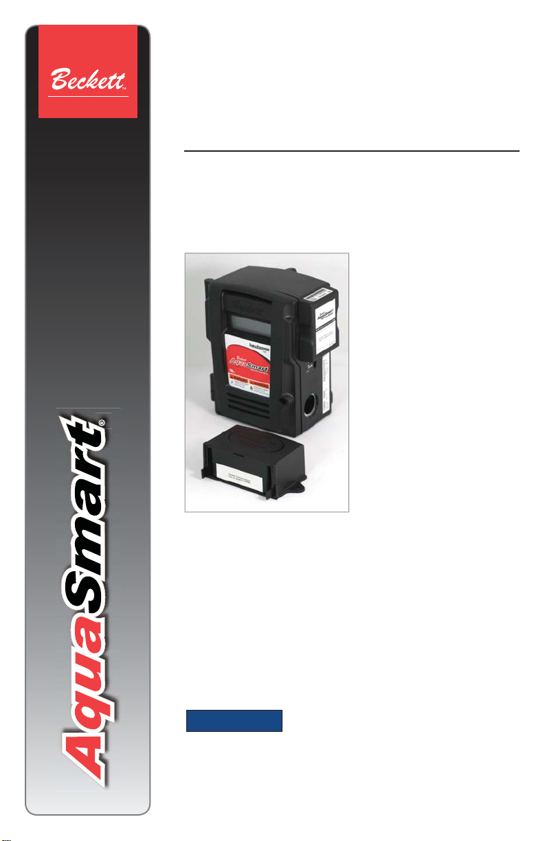
AquaSmart®
Wireless Temperature Module
Model 7600WTM
Wireless Outdoor Temperature Reset
Description / Applications
The Beckett AquaSmart®
Wireless Temperature Module
(WTM) is a 2-part accessory
for the AquaSmart boiler
control. It adds outdoor reset
capability to the AquaSmart
control by overriding the
control’s built-in HeatManager
algorithm when installed.
The wireless feature makes
installation easy by eliminating
mounting location limitations
for the outdoor sensor and
the need to run wires outside.
Outdoor Temperature Reset
(OTR) settings like reset ratio and boost have been made easier
to adjust and are accessible through the AquaSmart control’s
backlit LCD digital display. The WTM is backwards-compatible
with all existing AquaSmart controls. The WTM may provide
additional fuel savings over the built-in HeatManager algorithm
with the addition of a warm weather shutdown feature that can
disable the low limit. It is ideal for installations with high indirect
domestic hot water demands or a large water mass (such as
radiant in-fl oor heating).
NOTICE
Non-intended usage can cause damage to the WTM or the control
being connected to and potentially alter control or system operation.
This device is only for use in the United States and Canada.
○
For information regarding installation and operation of the
○
AquaSmart control, consult the latest revision of Beckett form
no. 61738 available at www.beckettcorp.com.
This accessory is NOT intended for use on any
other Non-AquaSmart Control or Equipment.
Page 2
Table of Contents
Features ...................................................................2
Technical Specifi cations ........................................2
Electrical Ratings ..............................................2
Environmental Ratings ......................................2
Approvals ..........................................................3
Operation .................................................................4
Installation ...............................................................5
Initial Set-up ......................................................5
Replacing the WTS battery ...............................7
Installing a new AWM or WTS ..........................7
Navigating the Display Menus ...............................8
Programming Basic Functions ..............................9
OTR ON/OFF: ...................................................9
High OAT: ..........................................................9
Low OAT: ...........................................................9
Boost: ................................................................9
Programming Additional Options..........................9
Heat Manager Effi ciency Setting: .....................9
Warm Weather Shut Down (WWSD): ...............9
Other Menu Items ................................................. 10
Current Outdoor Air Temperature (OAT): .......10
Signal Strength: .............................................10
Current WTS Battery Life: ..............................10
Adding Connections: ......................................10
Clearing Connections: ...................................10
Broadcast Once: ............................................10
Limited Warranty Information ............................. 12
T echnical Specifi cations
Electrical Ratings
AquaSmart Wireless Module:
Voltage: 5 Vdc +/- 4% (from AquaSmart COM
○
port)
Current: 45 mA max (from AquaSmart COM
○
port)
Line Power: 300 mW max (in addition to
○
AquaSmart’s power consumption)
Wireless Temperature Sensor Battery
Specifi cations:
NOTICE
not use the included battery in other devices.
3.6V, lithium, AA, button top, primary (non-
○
rechargeable) battery
Recommended replacement batteries
○
LS14500 (Saft), TL-5903 (Tadiran)
Do not return used or damaged batteries to the
○
manufacturer. Disposal of spent batteries should
be performed by an authorized, professional
disposal company, which has knowledge in the
requirements of the Federal, the State and the
Local authorities regarding hazardous materials,
transportation and waste disposal. Contact your
local EPA offi ce if unsure of how to dispose of
batteries properly.
Product will not function using
a standard 1.5V AA Battery. Do
Features
Wireless communication
○
10+ year battery life
○
Up to 200 ft. range from
○
boiler
Wireless module and
○
outdoor sensor are
linked together out of
the box.
Simple installation - no
○
wiring
Warm weather shutdown
○
2
Environmental Ratings
Storage and operating ambient temp.: -40 °F
○
to +150 °F (-40 °C to +65.6 °C)
Moisture:
○
AquaSmart Wireless Module: 5 to 95% RH, non-
a.
condensing and non-crystallizing.
Wireless Temperature Sensor: 5 to 95% RH,
b.
condensing. Weatherproof. Not submersible.
Risk of Fire, Explosion, and Burn
Hazard.
This control must be installed, adjusted
and put into operation only by a trained,
licensed, qualifi ed professional or
service agency.
Call RWB Technical Services at 1(800)645-2876 for
y
assistance.
Page 3
Approvals
This equipment has been tested and found to
comply with the limits for a Class B digital
device, pursuant to part 15 of the FCC Rules.
These limits are designed to provide
reasonable protection against harmful
interference in a residential installation. This
equipment generates, uses and can radiate
radio frequency energy, and if not installed and
used in accordance with the instructions, may
cause harmful interference to radio
communications. However, there is no
guarantee that interference will not occur in a
particular installation. If this equipment does
cause harmful interference to radio or television
reception, which can be determined by turning
the equipment OFF and ON, the user is
encouraged to try to correct the interference by
one or more of the following measures:
Reorient or relocate the receiving antenna.
1.
Increase the separation between the
2.
equipment and receiver.
Connect the equipment into an outlet on a
3.
circuit different from that to which the
receiver is connected.
Consult the dealer or an experienced radio/
4.
TV technician for help.
This device complies with Industry Canada
license - exempt RSS standard(s).
Operation is subject to the following two
conditions: (1) This device may not cause
interference, and (2) this device must
accept any interference, including
interference that may cause undesired
operation of the device.
Le présent appareil est conforme aux CNR
d’Industrie Canada applicables aux
appareils radio exempts de licence.
L’exploitation est autorisée aux deux
conditions suivantes: (1) l’appareil ne doit
pas produire de brouillage, et (2)
l’utilisateur de l’appareil doit accepter tout
brouillage radioélectrique subi, même si le
brouillage est susceptible d’en
compromettre le fonctionnement.
To satisfy FCC RF Exposure
requirements for mobile
and base station transmission devices, a
separation distance of 20cm (8”) or more
should be maintained between the antenna
of this device and persons during operation.
To ensure compliance, operation at closer
than this distance is not recommended.
The antenna(s) used for this transmitter must
not be co-located or operating in conjunction
with any other antenna or transmitter.
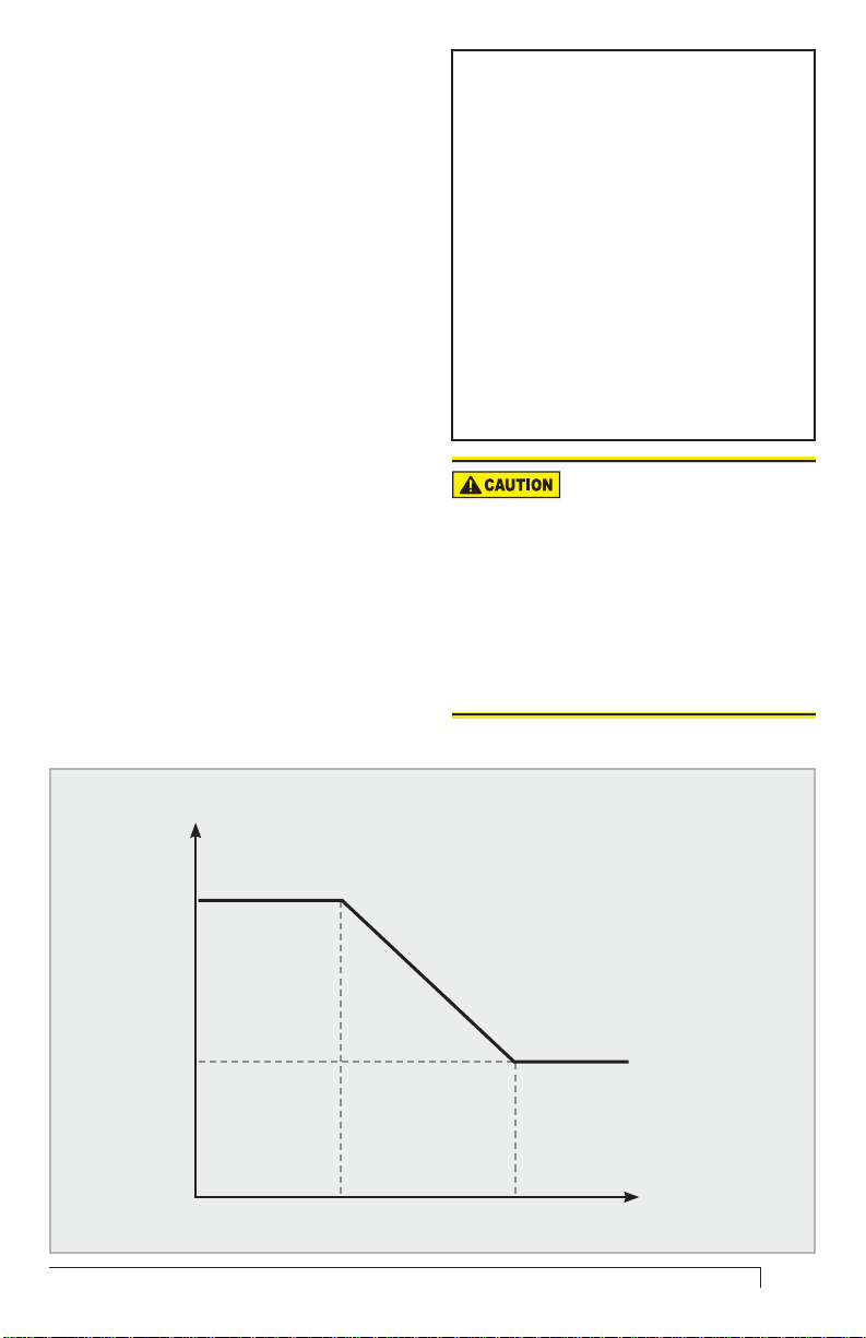
Figure 1 - Outdoor Temperature Reset Curve
RESET
TEMPERATURE
High Limit
Setting
Minimum
Reset
Temperature
Low
OAT
AquaSmart Wireless Termperature Module Manual
High
OAT
OUTDOOR AIR
TEMPERATURE
(OAT)
3
Page 4
Operation
The Beckett 7600AWM (AquaSmart
○
Wireless Module) dynamically adjusts the
boiler high setpoint using the graph shown
in Figure 1 and inputs of the outdoor
temperature and user-confi gurable
setpoints as noted in the fi gure.
○
The WTM algorithm overrides the
HeatManager
AquaSmart when enabled. If the outdoor
sensor battery is depleted or if the sensor
stops working for any reason, the AWM will
revert the AquaSmart back to its
HeatManager
can be replaced.
○
In normal operation, the WTS sends the
AWM the outdoor temperature every 10 60 minutes. Pressing the WTS button
once forces a transmission.
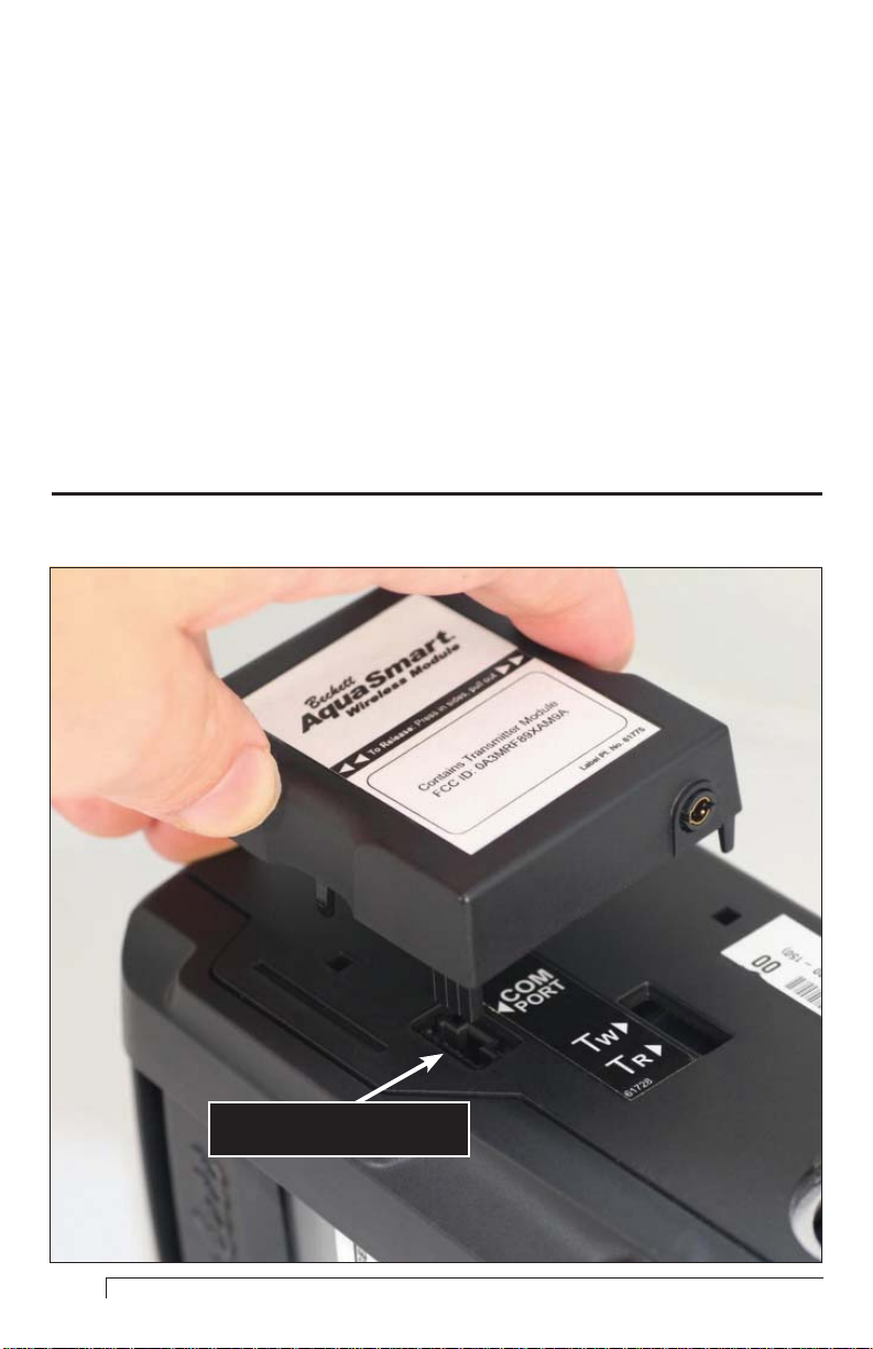
Figure 2 - AWM Installation
TM
functionality of the base
TM
algorithm until the battery
The Beckett 7600WTM can help to
○
achieve even greater fuel savings over the
base AquaSmart with the following
advanced features:
Warm Weather Shutdown can be
a.
enabled to turn the low limit (if used) off
if the outdoor temperature is above
70°F.
The boost function can be adjusted in
b.
small increments to prevent the reset
algorithm from being overridden too
quickly, which can benefi t systems with
high water mass (such as in-fl oor
radiant heating applications).
The outdoor reset algorithm begins
c.
economizing immediately after a
Domestic Hot Water (DHW) call for heat,
where the HeatManager takes time to
reach full economizing after a DHW call.
COM Port
4
Page 5

Figure 3 - How to open WTS
Installation
Risk of Fire, Explosion, and
Burn Hazard.
Do not attempt to recharge,
y
disassemble, heat above 85°C, expose
to water, puncture, incinerate, or shortcircuit the battery.
y
Keep battery out of reach of children and in
original package until ready to use.
y
Mount with battery at bottom position only.
Failure to do so could expose the battery to
water.
y
Dispose of used batteries promptly.
Initial Set-up
Remove power from the AquaSmart.
1.
Snap the AquaSmart Wireless Module
2.
(AWM) onto the COM Port (Figure 2) on the
side of the AquaSmart boiler temperature
control. Restore power to the AquaSmart
control.
Remove the internal cartridge containing the
3.
AquaSmart Wireless Termperature Module Manual
battery cell from the Wireless Temperature
Sensor (WTS). Press in the plastic tabs and
pull the cartridge out as shown in Figure 3.
Remove the plastic insert on the battery
4.
terminal. Make sure battery is inserted
properly (see polarity mark on battery
holder).
Mount the WTS with the two screws
5.
provided at your desired location. Mount the
sensor on any exterior wall (preferably on
the north face of the house), at least 6
inches below any vertical overhang, above
the snow line, out of reach of children, and
suffi ciently far away from any vents for them
not to affect temperature readings. Choose
a location protected from direct sunlight.
Use caution not to drill screws into any
existing electrical wiring or gas lines.
Verify operation:
6.
Press the WTS button once (Figure 4).
a.
The LED should fl ash fi ve times.
Using the AquaSmart’s display, navigate
b.
to Screen 1 as shown in Figure 5, in the
Navigating the Display Menus
Section.
5
Page 6

Figure 4 - WTS Internal View
LED
WTS Button
WARNING! Mount with battery at bottom position only.
Failure to do so could expose the battery to water.
The screen should display the current
outdoor temperature and show that the
last transmission was received within the
last few minutes. If “NOT INSTALD”
appears, the AWM and AquaSmart are
not communicating. Wait 30 seconds. If
the error persists, power down the
AquaSmart control, ensure the AWM is
properly connected, and restore power to
the control. If the OAT screen says “0F
AS OF 18:12 AGO”, press the WTS
button once. If the value does not
update, there is a problem with the
connectivity of the WTS. Move the WTS
to a location closer to the AWM or with
less interference.
6
c.
Navigate to screen 2. The signal strength
screen indicates the strength of the
connection between the AWM and WTS.
At least 3 darkened bars are
recommended for operation, with 6 or
more indicating a good connection.
Moving the WTS closer to the AWM or
away from large metal object can improve
the connection.
6.
On older AquaSmart controls, the OTR
may be off by default. Refer to the OTR
ON/OFF section of the Programming
Basic Functions Section to make sure it
is turned on.
7.
If modifying the default settings is desired,
the Programming Basic
refer to
Functions Section.
Page 7

Replacing the WTS battery
1.
To determine if battery needs replaced:
a.
Navigate to Screen 3 as shown in
Figure 5 (Navigating the Display
Menus). If the screen says
“REPLACE”, the battery needs
replaced.
b.
If the OAT Screen (screen 1) reads “AS
OF 18:20 AGO” the AWM is not
receiving transmissions from the WTS,
and the battery should be replaced.
To replace battery:
2.
Remove old battery from Wireless
a.
Temperature Sensor. The lithium battery
should be recycled.
Press button on Wireless Temperature
b.
Sensor once. This step is extremely
important to make sure the power from
the old battery is depleted so that the
sensor will know it has a new battery.
Insert new 3.6V lithium battery. See
c.
Technical Specifi cations Section for
battery specifi cations and replacement
part number. Make sure battery is
inserted properly (see polarity mark on
battery holder).
Installing a new AWM or WTS
If the pre-linked AWM or WTS must be
1.
replaced for any reason, the new pair of
devices must be linked before use. Follow
the steps below to link the new devices.
Installing a new AWM
2.
Remove power from the AquaSmart control.
Remove the old AWM from the control by
gently squeezing the sides of the device at the
indentations marked with arrows and then pull
away from the AquaSmart.
Snap the new AquaSmart Wireless
a.
Module onto the COM Port on the side of
the AquaSmart boiler temperature
control. Restore power to the control.
Clear the old link from the Wireless
b.
Temperature Sensor: Hold the button of
the WTS for fi ve seconds. The LED
should turn on. Within 5 seconds, press
the button once more to confi rm the
clearing. Once the link is cleared, the
LED will fl ash quickly for 2 seconds.
Proceed to
c.
AquaSmart Wireless Termperature Module Manual
Step 4.
Installing a new WTS
3.
Remove the battery from the old WTS
a.
and discard both. The lithium battery
should be recycled.
In the new Wireless Temperature Sensor,
b.
remove the plastic insert on the battery
terminal. Make sure battery is inserted
properly (see polarity mark on battery
holder).
c.
Mount the new Wireless Temperature
Sensor with the two screws provided at
same location as the old WTS.
d.
Clear the old link for the AquaSmart
Wireless Module: Navigate to Screen 10
as shown in Figure 5 (Navigating the
Display Menus). Press
clearing connections, and press ENTER
again to confi rm.
Proceed to Step 4.
e.
Linking the AWM and WTS
4.
Put the WTS in discovery mode: press
a.
the WTS button twice. The LED will fl ash
slowly until it fi nds the AWM (for up to 3
minutes).
While the WTS is still in discovery mode,
b.
put the AquaSmart Wireless Module in
discovery mode: Navigate to Screen 9
as shown in Figure 5 (Navigating the
Display Menus). Press ENTER to begin
searching for new connections. The
screen will read “SEARCHING… 3:00”
and count down from 3 minutes.
Once the AWM sees the WTS, the 4-digit
c.
Network I.D. of the WTS will appear on
the 2nd line of the AquaSmart’s display.
Pressing up or down will cycle through
multiple device I.D.s if more than one
WTS is found. Press ENTER twice on
the AquaSmart display to accept the
connection with the WTS. Once the two
are linked, the LED on the WTS will fl ash
quickly for 10 seconds and the
AquaSmart’s screen will read
“CONNECTED: XXXX“, where XXXX is
the Network I.D. of the WTS.
ENTER to begin
7
Page 8

Navigating the Display Menus
Use the following screen structure to navigate through the AquaSmart Wireless Module screens
available on the AquaSmart display. When navigating, always use the keypad as follows:
ENTER (RESET) – Enter menu
○
CANCEL (BACK) – Navigate up one level in menu structure
○
Up / Down Arrows – Flip through available screens in current menu
○
Note: Once in the wireless menu, the AquaSmart display is taken over by the AWM. The
○
screens may take a few seconds to update, and the buttons may have to be pressed more
deliberately. This is normal.
Figure 5 - Navigation Screen Menu
HEAT MANAGR MENU
ENTER TO VIEW
HISTORY MENU
ENTER TO VIEW
CIRCULATOR MENU
ENTER TO VIEW
MORE OPTIONS
ENTER TO VIEW
ECONOMIZER: ON
ENTER TO CHANGE
EFFICIENCY: MED
ENTER TO CHANGE
12
13
LWCO MENU
ENTER TO VIEW
PRESSURE MENU
ENTER TO VIEW
WIRELESS MENU
ENTER TO VIEW
DHWP: OFF
ENTER TO CHANGE
DEG (F/C): F
ENTER TO CHANGE
OTR MENU
ENTER TO VIEW
OAT: 72F
AS OF 00:02 AGO
SIGNAL STRENGTH:
■ ■ ■ ■ ■ ■ ■ ■ ■
BATTERY LIFE:
100% (10 YEARS)
OTR: ON
ENTER TO CHANGE
HIGH OAT: 70F
ENTER TO CHANGE
LOW OAT: 0F
ENTER TO CHANGE
WWSD: ON
ENTER TO CHANGE
BOOST: 1F
ENTER TO CHANGE
1
2
3
4
5
6
7
8
MAINTENANCE MENU
ENTER TO VIEW
CONNECTIONS
ENTER TO ADD
CONNECTIONS
ENTER TO CLEAR
BROADCAST ONCE
ENTER TO START
9
10
11
8
Page 9

Programming Basic
Functions
OTR ON/OFF:
1.
Navigate to Screen 4 as shown in Figure
5 (
Navigating the Display Menus
2.
Pressing
will toggle the setting on and off.
3.
ON (default) indicates that the outdoor
reset algorithm will override the
HeatManagerTM algorithm.
4.
OFF indicates that the HeatManagerTM
algorithm will be used.
5.
NOTE – the Economizer must be set to
ON for either algorithm to be used (see
Screen 12).
ENTER (RESET) on this screen
High OAT:
1.
Navigate to Screen 5 as shown in Figure 5.
2.
Press ENTER (RESET) on this screen and
follow the on-screen instructions to change
this setting.
3.
This number specifi es the outdoor
temperature at which the boiler reset
temperature will be at its minimum value.
See Operation Section for further
description of what this value indicates.
4.
Default is +70°F (+21°C). Range is +40°F
to +70°F (+4°C to +21°C)
5.
NOTE – the minimum reset temperature
value that the AquaSmart will economize
to is determined by a number of factors,
including the low limit setting and the
effi ciency setting (Programming
Additional Options Section). A lower
effi ciency setting can raise this minimum
temperature if needed for comfort.
Low OAT:
1.
Navigate to Screen 6 as shown in Figure 5.
2.
Press ENTER (RESET) on this screen and
follow the on-screen instructions to change
this setting.
3.
This number specifi es the outdoor
temperature at which the boiler high limit
will be at its maximum value. See
Operation Section for further description
of what this value indicates.
).
Default is 0°F (-18°C). Range is 0°F to
4.
+40°F (-18°C to +4°C)
NOTE – the maximum high limit value is
5.
determined by the high limit setting of the
AquaSmart
Boost:
Navigate to Screen 8 as shown in Figure
1.
5.
Press ENTER (RESET) on this screen and
2.
follow the on-screen instructions to change
this setting.
This number specifi es the value to be
3.
added to the reset temperature every 10
consecutive minutes of a call for heat.
This can help to ensure the heating
demand of the house will be met even if
the reset temperature is not high enough
to satisfy the heating demand
Default is 0°F. Range is 0°F to 10°F (0°C
4.
to 6°C)
Programming
Additional Options
Heat Manager Effi ciency Setting:
Navigate to Screen 13 as shown in Figure 5.
1.
Pressing ENTER (RESET) on this screen
2.
will toggle the setting between HI, MED,
and LOW.
This value can adjust the minimum high
3.
limit value that the AquaSmart will
economize to if needed for comfort.
Warm Weather Shut Down
(WWSD):
Navigate to Screen 7 as shown in Figure 5.
1.
Pressing ENTER (RESET) on this screen
2.
will toggle the setting on and off.
ON will turn the low limit of the AquaSmart
3.
off when the outdoor temperature is above
70°F (21°C). Turning this feature on can
help to increase fuel savings.
OFF (default) will not turn the low limit off
4.
based on outdoor temperature.
AquaSmart Wireless Termperature Module Manual
9
Page 10

Other Menu Items
Current Outdoor Air Temperature
(OAT):
See Screen 1 shown in Figure 5.
1.
This screen displays the most recent outdoor
2.
temperature received from the WTS, and the
hours and minutes since the last
transmission received.
Signal Strength:
1.
See Screen 2 shown in Figure 5.
2.
This screen displays a visual representation
of the connection strength between the AWM
and WTS. The number of darkened bars
(between 0 and 16, with 16 being the
strongest) indicates the strength. A
mimimum of 3 bars are recommended for
reliable operation, while at least 6 indicate a
good connection. Pressing the WTS button
once will update this value.
Current WTS Battery Life:
1.
See Screen 3 shown in Figure 5.
2.
This screen displays the most recent report
of the battery life of the WTS in percentage
of battery life left and estimated years of
service left. If less than a year of service life
is expected, the screen will say “REPLACE”.
Adding Connections:
1.
See Screen 9 shown in Figure 5.
2.
This screen is used when linking two devices
when a new one has been added (see
Installation Section).
Clearing Connections:
1.
See Screen 10 shown in Figure 5.
2.
This screen is used when clearing a link
between two devices that is no longer
needed (see Installation Section).
Broadcast Once:
1.
See Screen 11 shown in Figure 5.
2.
This screen may be used in linking
procedures with future Beckett wireless
products.
10
Page 11

NOTES:
AquaSmart Wireless Termperature Module Manual
11
Page 12

Limited Warranty Information
The R. W. BECKETT CORPORATION (“Beckett”) warrants to persons who purchase its
“Products” from Beckett for resale, or for incorporation into a product for resale
(“Customers”), that its equipment is free from defects in material and workmanship. To
qualify for warranty benefi ts, products must be installed by a qualifi ed service agency in full
compliance with all codes and authorities having jurisdiction, and used within the tolerances
of Beckett’s defi ned product specifi cations.
To review the complete warranty policy and duration of coverage for a specifi c product, or
obtain a written copy of warranty form 61545, please choose one of the following options:
Visit our website at: www.beckettcorp.com/warranty
1.
Email your request to: rwb-customer-service@beckettcorp.com
2.
Write to: R. W. Beckett Corporation, P. O. Box 1289, Elyria, OH 44036
3.
NOTE: Beckett is not responsible for any labor cost for removal and replacement of
equipment.
THIS WARRANTY IS LIMITED TO THE PRECISE TERMS SET FORTH ABOVE, AND
PROVIDES EXCLUSIVE REMEDIES EXPRESSLY IN LIEU OF ALL OTHER REMEDIES,
AND IN PARTICULAR THERE SHALL BE EXCLUDED THE IMPLIED WARRANTIES OF
MERCHANTABILITY AND FITNESS FOR A PARTICULAR PURPOSE. IN NO EVENT
WILL BECKETT BE LIABLE FOR ANY INCIDENTAL OR CONSEQUENTIAL DAMAGE OF
ANY NATURE. Beckett neither assumes, nor authorizes any person to assume for Beckett,
any other liability or obligation in connection with the sale of this equipment. Beckett’s
liability and Customer’s exclusive remedy is limited to the cost of the product.
CORPORATION
USA: P.O. Box 1289 ● Elyria, OH 44036
Canada: R.W. Beckett Canada, Ltd. ● Unit #3, 430 Laird Road ● Guelph, Ontario N1G 3X7
www.beckettcorp.com
Form No. 61776 R02, Printed in USA 11/11
 Loading...