

Page 1
PARTS & ACCESSORIES
Model 7590
Gas Power Burner Control
Description / Applications
The Beckett GeniSys Gas Power Burner Control is a
safety control designed for use on gas power burners.
This control is intended for use in residential and light
commercial gas heating applications. Applications may
include boilers, furnaces, water heaters, space heating
and commercial cooking equipment. The 7590 provides
supervision of a separate 120 Vac igniter, a 120 Vac
combustion blower motor, a 24 Vac gas valve and 24
Vac connections for an air proving switch (on 7590C,
D). The control uses ame rectication principles to
prove the presence of the burner ame. Basic diagnostic
information is provided through 3 LEDs. Additional
diagnostic information and control setup will be available
through a separate diagnostic tool.
Page 2

Contents
Features........................................................................................3
Specications .............................................................................. 4
Electrical Ratings .......................................................................... 4
Electrical Connections ................................................................... 4
Environmental Ratings .................................................................. 4
Approvals ...................................................................................... 4
Lockout Sequence Options ........................................................... 4
Timings ......................................................................................... 4
Control Cycling Rate ..................................................................... 4
Installation ....................................................................................6
Mounting ....................................................................................... 7
Transformer Sizing ........................................................................ 7
Spark Gap ..................................................................................... 7
Wiring ...........................................................................................7
Operation .....................................................................................8
7590T ............................................................................................ 8
Status & Diagnostics .................................................................. 8
Flame Signal Strength Indication .................................................. 9
Lockout .......................................................................................... 9
Reset from Lockout ....................................................................... 9
Lockout with Retry (Optional) ........................................................ 9
Stop/Hold Button ......................................................................... 10
Safety Check ............................................................................... 10
Check Safety Timings ................................................................. 10
Check for Normal Operation ....................................................... 10
Simplied Sequence of Operation ................................................11
Troubleshooting ........................................................................13
Troubleshooting Sequence ......................................................15
Limited Warranty Information ..................................................20
Hazard Denitions:
Indicates a hazardous situation that, if not avoided, will result in
death or serious injury.
Indicates a hazardous situation that, if not avoided, could result
in death or serious injury.
Indicates a hazardous situation that, if not avoided, could result
in minor or moderate injury.
Used to address practices not related to physical injury.
Safety instructions signs indicate specic safety-related
instructions or procedures.
2
Page 3
Features
◦ For use in Natural Gas or LP gas applications.
◦ Controls 120 Vac spark igniter, motor/blower and 24 Vac gas valve, 50/60 HZ
◦ Provides proof of ame through ame rectication using a separate ame rod
◦ Checks combustion air proving switch contacts (24 Vac) on 7590C and 7590D
models to prove moving combustion air and guard against welded contacts.
◦ Field selectable for either lockout or recycle on loss of combustion air
◦ Field selectable relight or recycle operation on loss of ame (may be factory locked)
◦ Field selectable single or multiple trials for ignition on some models (may be locked)
◦ Field selectable ignition timing on some models (may be factory locked)
◦ Field selectable pre-purge timing (may be factory locked)
◦ The microprocessor is checked for proper operation prior to each ignition cycle
◦ Check for welded valve relays on each cycle
◦ Mounts on standard 4 x 4 junction box
◦ 3 status LEDs supply basic diagnostics, additional diagnostic information and eld
conguration will be available through a separate diagnostic tool
◦ An optional separate alarm module provides alarm contacts (dry contacts)
◦ A reset button is standard on all controls, non-volatile manual reset logic is available
on specic models (7590C).
◦ Communication Port to connect diagnostic tool and alarm module
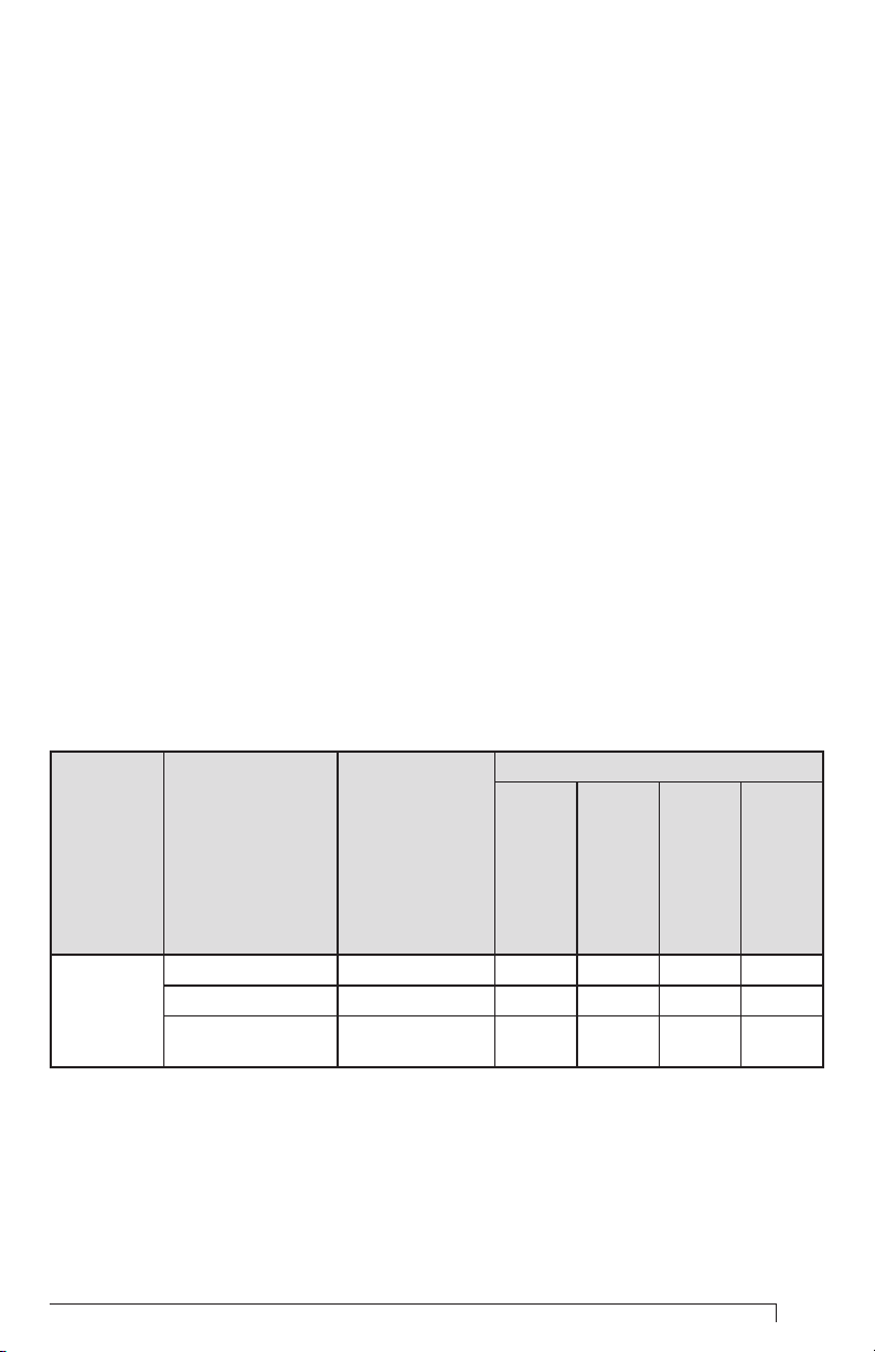
Table 1 - Ignition Model Numbers
Feature
Model Line Model Description Part Number
output
120 volt Igniter
and blower motor
Standard 7590DYYYY X X X
Gas Power
Burner
The standard model 7590 is designed for use on applications below 400,000 BTUs. For
applications above 400,000 BTUs, contact Beckett’s Engineering Group.
*Non-volatile lockout cannot be cleared by removing power from the control. The
control must be reset by pressing the Status/Reset button when the control is powered.
GeniSys Gas Power Burner Control Installation and Operation Manual
No Pressure Switch 7590TYYYY X X
Non-volatile Manual
Reset
7590CYYYY X X X X
output
24 volt gas valve
for
lockout*
Non-volatile
pressure switch
2 Pin- connector
3
Page 4

Specications
Electrical Ratings
◦ Voltage: 120 volts 50/60 Hz (igniter,
motor) 24 volts (18-30 Vac) 50/60Hz
(gas valve and air proving switch)
◦ Current Draw (run): 0.2 Amps (control
only)
◦ Main Valve Rating: 2.0 Amps
◦ Motor Relay Rating: 7.4 Amps (120V)
◦ Igniter Relay Rating: 1.0 Amp (120V)
◦ Minimum Flame Current Required:
1.0 µA
◦ Flame Failure Response Time: 0.8
Seconds (Max.)
◦ Control is not polarity sensitive
◦ Heat Anticipator Setting: 0.2 amp + gas
valve current draw
Electrical Connections
◦ Two T-T screw terminals (on top) (see
Figure 1)
◦ 1/4” Quick Connects (6 total on bottom)
─ Igniter, L2
─ Motor, L2
─ L1, L2
◦ 3/16” Remote Sense quick connect
terminal (on bottom)
◦ 6-Pin (24V) connector (on bottom)
24 Volt Input, Gas Valve, Burner
Ground
◦ 2-Pin (24 V) connector (on bottom)
Air Pressure Switch
◦ Micro-USB Communications Port (on
side of control) for diagnostic tool and
alarm module (COM1).
◦ Additional Features
◦ 3 Diagnostic LEDs; Status (red), Flame
(yellow), MV (green)
◦ Alarm Contacts (optional module)
Environmental Ratings
◦ Operating Temperature Range: -40°F
to +175°F (-40°C to +79.4°C).
◦ Relative Humidity Operating Range 5%
- 95% (non-condensing).
Not intended for outdoor use unless
mounted in appropriate enclosure.
Approvals
ETL listed per ANSI Z21.20 and CSA
C22.2#199
Lockout Sequence Options
◦ Sequence is usually factory selected
◦ Lockout after single try for ignition
◦ Lockout with retrial every 1-8 hours
◦ Lockout after 3 trials for ignition
◦ Manual Reset logic: shutdown after
failure to light during trial for ignition
timing or after ame failure, (no relight
attempt), after 5 minute minimum
waiting time, 1 retry attempt allowed,
then non-volatile lockout. Lockout
must be manually reset.
Timings
◦ All timings can be factory locked.
Timings below may be eld selectable
on some models.
◦ Ignition Timing: 4-15 seconds (4
seconds if Manual Reset)
◦ Pre-purge timing: 1-240 seconds
◦ Inter-purge timing: 90-300 seconds
Control Cycling Rate
The 7590 is designed for use in typical
heating applications which cycle a
few times per hour during the heating
season. More rapid cycling of the control
will shorten the useful life of the control.
Controls in rapid cycling applications
should be checked monthly for proper
operation. All controls should be checked
at least annually for proper operation.
4
Page 5
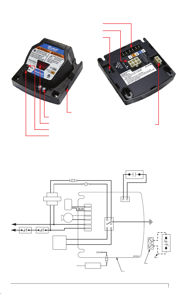
Figure 1 - Getting to know the control
1/4” Terminal Connections
6-Pin 24 V Connector
Flame Sense
Com Port (COM 1)
Thermostat Terminals
Status/Reset LED Button
Flame LED
MV LED
Figure 2 - Gas Conversion Burner Hookup Drawing
Air Pressure Switch
Transformer
W W
B
Limit
(If Required)
LWCO
Y/W
Y BK
Igniter
B
W
Burner
Motor
B
Gas
Valve
(1/4” QC)
W
W
O
W
V
L2 (IGN)
Igniter
L2 (MTR)
Motor
L2
L1
Valve Common
Sense
(3/16” QC)
Flame Sensor
W/R
Valve
24V
24V GROUND
Y
Y
AP1
GeniSys Gas Power Burner Control Installation and Operation Manual
Air Pressure
Switch
BR
BR
AP2
Burner Ground
G
Com Port (COM 1)
on side of control
Thermal
Switch
T
T
Field Wiring
TT Terminals on top
of control
5
Page 6
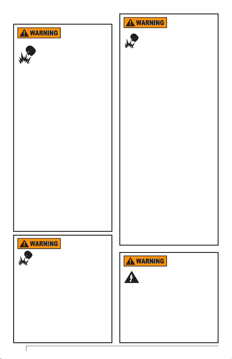
Installation
Professional
Service Required
Incorrect installation or
misuse of this control could
result in severe personal
injury, death, or substantial
property damage from explosion or re.
Read and understand this manual. This
control must be installed, congured
and put into operation only by a qualied
individual or service agency that is:
• Licensed or certied to install and
provide technical service to gas
heating systems.
• Experienced with all applicable
codes, standards and ordinances.
• Responsible for the correct
installation and commissioning of
this equipment.
The installation must strictly comply
with all applicable codes and authorities
having jurisdiction and the latest
revision of the National Fire Protection
Association Standard or CSA Standard
for the installation of gas controls in the
appropriate gas appliance.
Regulation by these authorities
take precedence over the general
instructions provided in this
installation manual.
Fire or Explosion
Hazard
Can cause severe injury, death,
or property damage.
If You Smell Gas or Believe a Leak May
Exist
• Turn off the manual gas valve to
the appliance.
• Leave the building.
• Do not try to light the appliance.
• Do not touch any electrical switch.
• Do not use a telephone within the
building.
• Leave the building before calling
the appropriate gas organization
Explosion, Fire,
Scald, and Burn
Hazard
Can cause severe injury, death,
or property damage.
• The control can malfunction if it gets
wet, leading to an accumulation of
explosive gas vapors.
• Never install where water can ood,
drip or condense on the control.
• Never use a control that has been
wet - replace it.
--------------------------------------
All heating appliances must have HIGH
LIMIT protection to interrupt electrical
power and shutdown the burner if
operating or safety controls fail and
cause a runaway condition.
• Follow the appliance
manufacturer’s wiring diagrams
and note all required safety
controls.
• Typical safety controls include
high temperature or pressure
limits, low water cutoffs, pressure
relief valves and blocked ue
sensing switches.
• Verify all limit and safety controls
are installed and functioning
correctly, as specied by the
manufacturer, applicable
safety standards, codes and all
authorities having jurisdiction.
• Ensure that gas or gas vapors
have not accumulated in the
appliance before starting or
resetting the burner.
Electrical Shock
Hazard
Electrical shock can cause
severe personal injury or
death.
• Disconnect ALL electrical power to
the appliance/burner circuit before
installing or servicing this control.
• Provide ground wiring to the
appliance and burner.
• Perform wiring in compliance with
the National Electrical Code ANSI/
NFPA 70 (Canada CSA C22.1).
6
Page 7

No User
Serviceable Parts
• Do not open control.
• Do not attempt to replace any
components.
Mounting
The control should be mounted
in accordance with the burner
manufacturer’s or appliance
manufacturer’s instructions. If this is
a replacement application, mount the
control in the same location as the existing
control. The 7590 control is designed to
mount on a 4” x 4” junction box on the
burner. Avoid mounting locations where
water could drip on the control. Mounting
location must remain within the -40°F
(-40°C) to +175°F (79.4°C) operating
temperature range.
Mounting location should protect against
moisture, corrosive chemicals, excessive
dust or water. If any of the above
elements are present, control should be
mounted in a NEMA 4 rated enclosure.
Transformer Sizing
A transformer with a 24 volt secondary
is required to power the control and gas
valve. To calculate the minimum VA
transformer needed:
Voltage X Amperage = VA rating needed
Voltage = 24 Vac
Amps (0.2 amps + gas valve current draw)
Example:
0.2A (7590) + 0.5A (gas valve) = 0.7 A
0.7A X 24V = 16.8 VA or 20 VA transformer
Spark Gap
Follow appliance manufacturer’s or burner
manufacturer’s instructions for setting the
proper ignition electrode spark gap.
Wiring
Reference Figure 2 for wiring diagram.
Electrical Shock
Hazard
Electrical shock can cause
severe personal injury or
death.
Make sure all wiring is securely installed
on the control. Failure to secure the wiring
properly can lead to electrical shock.
To Prevent
Shock or
Damage to the Appliance or the
Control, Remove Power Before
Making Any Wiring Connections.
Do not short out gas valve or control
terminals during testing. Shorting could
cause damage to the thermostat or
control and could cause personal injury or
property damage.
Incorrect Wiring
Will Result in
Improper Control Operation
• Label all wires prior to
disconnection when servicing
controls
• GeniSys wiring order and colors
may not match the wire order and
colors of the appliance or other
manufacturers’ controls.
• The GeniSys Control should be
wired according to the appliance
manufacturer’s instructions.
DO NOT connect
any cell phone,
tablet or computer to the
communications port. Any device
connected to the port will be
damaged.
GeniSys Gas Power Burner Control Installation and Operation Manual
7
Page 8

Wiring must comply with all national and
local codes. Wiring must follow appliance
and burner manufacturer’s instructions.
Follow the appropriate hook up drawing
for the application in which the control is
being installed.
The ignition cable length
should be 3 feet or less,
or meet igniter manufacturer’s specied
length. Avoid placing the ignition cable in
direct contact with metal surfaces as
reduced spark voltage could result. Use
plastic or ceramic standoffs if necessary.
The control, electrode
and ame sensor must
have a common ground with the main
burner for proper operation. Failure to
provide proper ground for the control,
electrode and sensor may result in a failure
to sense the presence of ame. Failure to
sense ame will result in lockout or
continued cycling of the ignition sequence.
On models with Air
Pressure Switch
terminals (7590C, D), do not place a
jumper on the Air Pressure Switch
terminals. Placing a jumper on the
terminals will cause the control to lockout.
The Air Pressure Switch must be in place
for the control to operate properly
Frozen Plumbing
and Water
Damage Hazard
If the residence is unattended in
severely cold weather, burner primary
control safety lockout, heating system
component failures, power outages or
other electrical system failures could
result in frozen plumbing and water
damage in a matter of hours.
For protection, take preventive actions
such as having a security system installed
that operates during power outages,
senses low temperature and initiates an
effective action. Consult with your heating
contractor or a home security agency.
Operation
Fire or Explosion
Hazard
Can cause severe injury, death,
or property damage.
Replacement control must be congured
to match all timings, settings, and pre-
purge of the control being replaced.
• DO NOT USE A TRIAL FOR
IGNITION TIMING LONGER
THAN THE TIMING ON THE
ORIGINAL CONTROL. Severe
injury, death, or substantial
property damage could result from
a longer trial for ignition timing.
• MATCH THE LOCKOUT LOGIC
SEQUENCE TO THE ORIGINAL
CONTROL. If the original control
is a single trial for ignition or
allows three trials for ignition
before lockout, the replacement
control must match the number of
ignition trials.
Fire or Explosion
Hazard
Can cause severe injury, death,
or property damage.
USE 7590 GAS BURNER CONTROL ONLY
WITH BECKETT 7474001 GAS IGNITER.
Use with other igniters could result in
allowing gas ow when ame is not
present.
7590T
The 7590T may replace some existing burner
controls designed for 24 volt gas valves. The
7590T cannot be used to replace controls
designed for use with line voltage (120 Vac)
gas valves or controls with pressure switch
connections. Settings are locked after 4
hours of burner operation.
Status & Diagnostics
The 7590 module has 3 LED lights
8
Page 9

that help provide status and diagnostic
information. Reference Figure 1. The
three LEDs are Status, Flame, and MV
(main valve). The LEDs use 4 modes;
On, Off, Slow Flash, Fast Flash.
◦ The air pressure switch fails to close
after the motor/blower starts
If the control is programmed for 3 trials for
ignition, the control will lockout after the
3rd unsuccessful attempt.
◦ Flame (yellow) = Flame Sense, Flame
Strength
◦ MV (green) = Gas Valve On/Off
◦ Status/Reset (red) = Power, Lockout,
Pre-Purge, or Waiting
The tables on Normal LED Sequence,
LED Diagnostic Help and Troubleshooting
describe the information available through
the LEDs.
Flame Signal Strength
Indication
The 7590 uses ame rectication to
prove the presence of the burner ame.
For reliable operation, a strong ame
current is needed. The yellow Flame LED
provides a reliable indication of the ame
current strength.
When the burner is lit;
◦ A continuously on Flame LED indicates
a strong ame current.
◦ A slowly ashing Flame LED indicates
a marginal ame current strength.
Consider adjusting the electrode or
ame rod to improve the ame signal.
If the Flame LED is off, no ame is being
detected. Refer to the Troubleshooting
Section to resolve the issue.
Lockout
If the red Status/Reset button is ashing
rapidly (3 times per second), the control is
in lockout. All control outputs are turned off
and the control will not respond to a call for
heat. The control enters lockout when:
◦ The control fails to prove ame during
the trial for ignition period
◦ The control fails the relay check
◦ The air pressure switch is closed(stuck)
at the beginning of the ignition
sequence
Fire or Explosion
Hazard
Can cause severe injury, death,
or property damage.
• Be sure that gas or gas vapors
have not built up in or around
the appliance before starting or
resetting the burner.
• Turn thermostat or controller
off and wait 5 minutes before
attempting to start or reset burner.
Reset from Lockout
To reset the control from lockout, push the
red Status/Reset button when there is power
to the control. The button does not need
to be held down for the control to reset.
Following reset, the control will start the
ignition sequence. The standard control can
also be reset by removing power from the
control for 10 seconds, then restoring power.
Standard Control Models: 7590D or T
have volatile lockout and can be reset by
removing, then restoring power or pushing
the red Status/Reset button.
Non-Volatile Lockout Model: 7590C cannot
be reset by removing and restoring power.
Lockout must be reset by pushing the
Status/Reset button while the control is
powered.
Lockout with Retry (Optional)
Interruptions in the gas supply can prevent
the burner from lighting during the trial for
ignition and cause the control to lockout. If
the house or building is unoccupied for long
periods during cold weather, a lockout can
lead to low temperatures or freezing in the
structure.
GeniSys Gas Power Burner Control Installation and Operation Manual
9
Page 10

The 7590D and T models can be congured
to automatically allow an ignition retry
once every 1-8 hours (selectable using the
diagnostic tool or by factory conguration).
This conguration may help by allowing
periodic ignition retries until the gas supply
is restored. The ignition retries will only
happen if there is power to the burner and
there is a call for heat from the thermostat or
controller. The control will not allow retry if
the lockout was caused by a failed gas valve
relay check. This retrial feature may not be
available (factory locked) in some controls
including the 7590C version.
If the red Status/Reset button is ashing
slowly (1 time per second) and the motor/
blower is off, the control is waiting for retrial.
When the standard control (7590D and T) is
in the waiting period, it can only be reset by
removing power from the control.
Stop/Hold Button
Holding the Status/Reset button down for
more than 1 second will interrupt the ignition
sequence. The control will enter a hold
mode and all control functions will stop.
When the Status/Reset button is released,
the control will start the ignition sequence
over (including pre-purge).
supply system using a soap and water
solution or electronic detection.
Check Safety Timings
◦ Turn off gas supply to appliance.
◦ Restore power to the appliance.
◦ Turn the thermostat or controller up
to call for heat. Status LED should be
powered. Motor should start.
◦ Following pre-purge, the control will
energize the separate igniter, spark
should be present at the burner head.
MV LED should light and gas valve
should open.
◦ Spark should stay on for the entire
ignition timing.
◦ Spark should switch off at the end of the
ignition timing. Gas valve and MV LED
should turn off.
◦ If the control is programmed for single
trial for ignition, the Status LED will ash
rapidly to indicate lockout.
◦ For controls programmed for multiple
trials for ignition, allow the control to
continue retrials until lockout occurs.
Status LED will ash slowly during
waiting period between ignition cycles.
Safety Check
Before starting appliance, make sure that
all wiring is correct and secure. Repair or
replace any loose connections or damaged
wire. Use only wire rated for the application.
◦ Use UL approved wire of the gauge
and temperature rating specied by the
appliance or burner manufacturer for any
replacement wiring.
◦ Use UL approved solid conductor ignition
cable. Cable must meet the temperature
and voltage ratings specied by the
manufacturer. Use insulated boots or
terminals, if needed, to prevent sparking
to burner parts.
Perform a visual
inspection of all system
components including the gas supply
system. Check for any leaks in the gas
10
Check for Normal Operation
◦ Restore power to the appliance.
◦ If control is in lockout push Status/Reset
button.
◦ Turn manual gas cock to on position.
◦ Turn gas valve to on position using either
the manual gas knob or the electrical
switch on the valve.
◦ Turn the thermostat or controller up to
call for heat. Status LED should be
powered. Motor should start.
◦ Following pre-purge, the igniter will be
turned on and spark should be present
at the burner head. The MV LED should
turn on and the gas valve should open.
Motor continues running.
◦ When the burner is lit by spark, ignition
Page 11

will shut off and the main gas valve will
remain open.
◦ Multiple ignition trials may be needed to
establish gas ow on new installations or
if burner has been out of use. If control
locks out, push Status/Reset button to
restart ignition sequence.
◦ When the burner lights, the Flame LED
should be on continuously.
◦ Check burner for proper combustion per
burner or appliance instructions.
◦ Remove call for heat by turning the
thermostat or controller down.
◦ The MV LED, Flame LED and Status
LED should go off. The valve should
close. Motor should turn off.
◦ The burner should turn off quickly.
Simplied Sequence of Operation
(Reference Table 2)
◦ Call for heat, Status LED is turned on.
◦ Control performs safe-start check
◦ If safe-start fails, control locks out.
◦ If safe-start passes, control checks for
presence of ame.
◦ If ame is present, control will enter hold
state until ame is no longer present.
Flame LED and Status LED will ash
until ame is no longer present.
◦ If ame is not present, control will check
status of air proving switch. If switch is
closed, (indicating the pressure switch is
stuck) control will enter lockout.
◦ If the air proving switch is open, the
motor will start. Once the air proving
switch closes, pre-purge will begin
(lasting 1-240 seconds). Pre-purge or
ignition timings will not start until the air
proving switch closes.
◦ The air proving switch must close to
prove combustion air is present. If switch
fails to close during the specied period,
the control will enter lockout.
◦ When pre-purge is completed, the control
turns on the igniter and the gas valve.
MV LED will turn on.
◦ Spark continues until end of ignition
timing or until ame is proved.
◦ Once ame is proved, The Flame LED is
turned on and the spark is turned off. The
gas valve and MV LED remain energized.
◦ If ame is not proved, the control will
lockout or enter the inter-trial waiting
period. Status LED will ash rapidly for
lockout or slowly for inter-trial waiting.
◦ If multiple trial logic is used, the control
will complete the trials for ignition
◦ When ame is proved the control will
continue in run mode until the end of
the call for heat.
◦ When the call for heat is ended, the
gas valve, MV LED, Flame LED, Status
LED and motor turn off.
Table 2 - Operating Sequence
Call for Heat
LEDs
Timers &
Timings
Flame Check On On On On On
Motor/Blower Blower Starts On On On Off
Air Switch Check On Air Switch Closes On On On
Igniter On Off Off
Gas Valve On On Off
GeniSys Gas Power Burner Control Installation and Operation Manual
FLAME
MV STATUS
Status LED
turns on
Motor Start
FLAME
MV STATUS
Status LED
ON
Pre-purge
FLAME
MV STATUS
Status LED
Flashes
Pre-purge Timer
1 - 240 Seconds
Ignition
FLAME
MV STATUS
Status, MV
LEDs On
Ignition Trial
Timer
4 - 15 Seconds
Run
FLAME
MV STATUS
Status, MV,
Flame LEDs On
End Call for Heat
FLAME
MV STATUS
LEDs Off
11
Page 12

LED Key:
= OFF
= ON
= FLASHING
For below charts, “Troubleshooting” &
“Troubleshooting Sequence” sections.
Table 3 - Normal LED Sequence
LED LED STATE CONTROL STATE
All LEDs off No call for heat or no power to
FLAME
MV STATUS
appliance
Note: On a call for heat, after the motor/blower starts, the air proving switch must
close before pre-purge or trial for ignition timers can start. The Status LED may turn
on momentarily while waiting for the air pressure switch to close. If pre-purge is set
for 1 second, once the air pressure switch closes, the control will move directly to trial
for ignition without ashing the Status LED for pre-purge.
FLAME
MV STATUS
FLAME
MV STATUS
Status LED ashes slowly
(once per second) but only if
control is set up for pre-purge
of 2 seconds or more
Status and MV LEDs on
continuously
Pre-purge or waiting period
between trials for ignition,
motor should be running
Trial for Ignition, motor should
be running and ignition should
be sparking
Status, Flame and MV LEDs
FLAME
MV STATUS
all on continuously
Table 4 - Additional LED Diagnostic Help
LED LED STATE CONTROL STATE
FLAME
MV STATUS
FLAME
MV STATUS
FLAME
MV STATUS
FLAME
MV STATUS
Status LED is ashing quickly,
3 times per second
Status,Flame and MV LEDs all
ashing
Status and Flame LEDs
ashing
Status and MV LEDs on
continuously, Flame LED
ashing
Main ame has been proved,
Control is in run mode and will
continue in run mode until call
for heat ends
Control is in lockout,
follow reset steps under
troubleshooting box “If the red
Status LED is ashing quickly”
Control failure - internal error,
try resetting the control once, if
problem reoccurs, replace the
control
Flame has been sensed when
ame should not be present,
follow troubleshooting under
“If the red Status and yellow
Flame LEDs are both ashing”
Flame signal is weak, follow
troubleshooting steps under “Is
the yellow Flame LED on?”
12
Page 13

Troubleshooting
Check LEDs First - Find the box on the left that matches the LED display you are seeing.
When all three LEDs are on continuously and the burner is lit, the system is
operating normally. The troubleshooting information is intended as a guide and may
not cover all possibilities in every application.
Table 5 - Troubleshooting
If the red Status LED is off:
▪ No power to the control.
▪ Check that the thermostat or controller is calling for heat.
▪ Check for power to the appliance.
▪ Check that limit is closed, check that the thermal (blocked vent)
switch is closed.
FLAME
MV STATUS
FLAME
MV STATUS
FLAME
MV STATUS
FLAME
MV STATUS
GeniSys Gas Power Burner Control Installation and Operation Manual
▪ Check for power to the system transformer.
▪ Check all wiring and secure all connections
▪ With the controller calling for heat, use a volt meter to measure 24
volts to the control. Place one probe on the right thermostat terminal
and the other probe on an unpainted portion of the burner. If no
voltage is measured, there is no power to the control. If 24 volts is
measured, move the rst probe from the right thermostat terminal
to the left thermostat terminal. If 24 volts is measured on the left
terminal and the red Status LED is off, replace the control. If no
voltage is measured on the left terminal, the thermal switch is open.
If only the red Status LED is on steadily:
▪ If motor is off—air pressure switch is closed (stuck), will wait for
switch to open.
▪ If motor is on—waiting for air pressure switch to close.
▪ If switch fails to open or close within a specied time, control will lockout.
▪ If switch opens and closes properly, control will move to pre-purge.
If the red Status LED is ashing quickly (3 times per sec.)
▪ Control is in lockout.
▪ Check the air pressure switch. If the air pressure switch is stuck in
the closed position or if the air pressure switch has been jumpered,
the control will lockout. The control will also lockout if the air pressure
switch fails to close when the motor/blower starts. Check to make
sure motor and blower are running during trial for ignition.
▪ Push the reset button or turn the thermostat or controller to off posi-
tion, wait 10 seconds then turn thermostat or controller to call for heat.
▪ If control is a non-volatile lockout model (7590C), the control can only
be reset using the reset button while the module is powered.
▪ Control should start ignition sequence. Motor/blower should be on.
▪ If burner does not light properly, follow the troubleshooting sequence.
If the red Status LED is ashing slowly (1 time per sec.)
▪ If motor/blower is running, control is in pre-purge or control is in a
waiting period between trials for ignition. If motor is not running, con-
trol is in soft lockout waiting to retry in 1-8 hours (reset control).
▪ The pre-purge period is 1-240 seconds, depending on setting.
▪ The control waiting period is 90 seconds to 5 minutes, depending on
setting.
▪ Either wait for pre-purge/waiting period to nish, OR
▪ Turn thermostat or controller off for 5 minutes to let accumulated gas
disperse, (LED should turn off) then turn thermostat or controller back
on to restart ignition sequence. Allow the control to go through pre-
purge, if any, and complete the trial for ignition sequence.
▪ If burner does not light properly, follow the troubleshooting sequence.
Table 5 continued on next page ►
13
Page 14

Table 5 (continued)
FLAME
MV STATUS
FLAME
MV STATUS
FLAME
MV STATUS
If the red Status LED and green MV LED are on continuously
▪ Call for heat is active.
▪ Control is powered.
▪ Igniter should be energized and sparking at the burner head, gas
valve should be open, motor should be running.
▪ If no sparking at the burner, follow the troubleshooting sequence.
If the Status and MV LEDs are on continuously and the Flame LED is
ashing
▪ The ame signal is weak
▪ Try to improve ame signal strength by following steps in the Trouble-
shooting Sequence under “Is the yellow Flame LED on?”
If the red Status and yellow Flame LEDs are both ashing
▪ The control is sensing ame when no ame should be present.
▪ The control enters a hold state, this is not a lockout.
▪ Control will remain in hold state until ame is no longer present.
▪ Check for ame in the burner.
▪ Check gas valve for leakage through the valve, replace valve if leak-
ing.
▪ Measure gas pressure to make sure pressure does not exceed valve
rating.
▪ Maximum gas pressure rating will often be listed on gas valve.
▪ If pressure is too high, adjust gas pressure at system regulator or
contact gas utility for help.
▪ High gas pressure can damage gas valves, if gas pressure exceeding
the rating of the valve is measured, the gas valve should be replaced.
FLAME
MV STATUS
▪ An internal error has been detected, try resetting the control once, if
the problem reoccurs, replace the control
If all the LEDs are on continuously and the burner is lit
If all the LEDs are ashing
FLAME
MV STATUS
▪ The control is in the run mode and is functioning properly.
Fire or Explosion
Hazard
Can cause severe injury, death,
or property damage.
Do not use a ame simulation device for
troubleshooting. Using a ame simulator
could by-pass system safety and allow
gas ow without ame. Use the Flame
LED to conrm the ame signal presence
and strength.
14
Page 15

Troubleshooting Sequence
Start with gas supply off and set thermostat or controller to call for heat.
Is the red
Status LED on?
YES
Pre-Purge
FLAME
MV STATUS
Pre-purge
complete?
1-240 sec.
YES
NO
NO
FLAME
MV STATUS
▪ No power to the module.
▪ Check to make sure thermostat or controller is calling for
heat and limit is closed.
▪ See instructions in troubleshooting box “If the red Status
LED is off”.
▪ If red Status LED is ashing slowly (1 time per second)
control is in pre-purge, motor should be running.
▪ If red Status LED is ashing quickly (3 times per second)
control is in lockout. Check the air pressure switch and
follow steps under troubleshooting box “If the red Status LED
is ashing quickly”.
▪ If red Status LED is on steadily, the control is waiting for the
air pressure switch. See instructions “If the red Status LED
is on steadily”.
▪ Status LED will ash approximately once per second during
pre-purge. Burner motor should be running.
▪ Wait for the control to complete the pre-purge timing.
▪ Note: Status LED does not ash for a 1 second pre-purge.
Trial for Ignition
FLAME
MV STATUS
Is the igniter
sparking during
NO
trial for ignition?
YES
Continued on
next page
GeniSys Gas Power Burner Control Installation and Operation Manual
▪ If both Status and MV LEDs are lit, control is in trial for
ignition, the igniter should be sparking and motor running.
▪ Check incoming line voltage to burner and control (120 V)
▪ With power off, check all wiring and connections to igniter.
▪ Check for correct spark gap on ignition electrode.
▪ Check ignition cable and ground wire for continuity, replace
if necessary.
▪ If ignition cable shows signs of melting or wear, replace and
reroute or shield cable.
▪ Check ceramic insulator around the electrode for cracking
or chipping, replace if needed.
▪ With power off, loosen 7590 from junction box, carefully
remove female quick connect terminals from Igniter and L2
male terminals. Restore power and start ignition sequence.
With the Status and MV LEDs on, carefully measure the
voltage between male Igniter and L2 terminals. Voltage
should be 120 Vac. If no voltage, replace control.
▪ If voltage between Igniter and L2 terminals is 120 volts and
all connections to igniter, electrode and ground are good,
replace igniter.
15
Page 16

Troubleshooting Sequence (continued)
► Turn the thermostat or controller off to end the call for heat.
► Turn on the gas supply.
► Turn the thermostat or controller back on to call for heat.
The ignition sequence will start over.
Repeat the steps above and proceed to lighting the burner.
FLAME
MV STATUS
Does the burner
light?
YES
NO
▪ If burner fails to light, control will lockout or enter waiting period.
▪ If gas was owing, wait for gas to disperse.
▪ Reset the control and repeat the ignition sequence.
▪ It may take more than one ignition cycle for gas to reach the
burner after being off. Reset the control if needed.
▪ Make sure the gas supply and all manual shutoffs are open.
▪ With the MV LED on, check for 24 volts at the gas valve.
▪ If 24 volts is not present at the valve, check any safety device in
gas valve wiring.
▪ Turn off power and check all wiring for continuity between the
control module and the gas valve. Turn power back on.
▪ If all wiring is good and still no voltage is present at the gas
valve with MV LED on, replace the control module.
▪ Check gas supply for any leaks using a soap and water solution
or electronic detection.
▪ Measure gas pressure for low input pressure. Pressure must
match gas input pressure listed on rating plate.
▪ Adjust gas pressure at system regulator if necessary or contact
gas utility for help.
▪ If there is gas pressure at the valve inlet and 24 volts is present
at the gas valve but no gas ow through the valve, replace the
gas valve
Continued on
next page
16
Page 17

Is the yellow
Flame LED on?
YES
NO
FLAME
MV STATUS
▪ Flame is not being proven, control will lockout or enter waiting period.
▪ With power off, check the electrical connections from the control to
the ame rod.
▪ Make sure all connections are clean and free of corrosion or build up.
▪ Check the continuity of the ground wire and the sense wire.
▪ The control, electrode and ame sensor must have a common ground
with the burner for proper operation.
▪ Check the ceramic on the ame rod for any chips or cracks, replace
if needed.
▪ Check the ame rod for build up and clean or replace if needed.
▪ Make sure the electrode and ame rod are covered with a steady,
stable ame, adjust ame rod or electrode if needed.
▪ Restore power, if ame is still not being proven, replace the control.
FLAME
MV STATUS
FLAME
MV STATUS
Note: If Flame LED is ashing slowly,
follow these same steps to improve
ame signal strength and reliability.
Normal run mode
FLAME
MV STATUS
▪ When the burner lights successfully, turn the thermostat or controller off to end the call for heat.
▪ The burner should go out quickly. All LEDs on the control should go out.
▪ If the burner remains lit for more than a few seconds, and the MV LED is out, replace the gas valve.
▪ If the LEDs remain lit, check the thermostat or controller for proper operation.
▪ Repeat the ignition sequence several times to make sure the system is operating properly.
GeniSys Gas Power Burner Control Installation and Operation Manual
17
Page 18

Page intentionally left blank
18
Page 19

Page intentionally left blank
GeniSys Gas Power Burner Control Installation and Operation Manual
19
Page 20

Limited Warranty Information
The R. W. BECKETT CORPORATION (“Beckett”) warrants to persons who
purchase its “Products” from Beckett for resale, or for incorporation into a
product for resale (“Customers”), that its equipment is free from defects in
material and workmanship. To qualify for warranty benets, products must be
installed by a qualied service agency in full compliance with all codes and
authorities having jurisdiction, and used within the tolerances of Beckett’s
dened product specications.
To review the complete warranty policy and duration of coverage for a specic
product, or obtain a written copy of warranty form 61545, please choose one of
the following options:
1. Visit our website at: www.beckettcorp.com/warranty
2. Email your request to: rwb-customer-service@beckettcorp.com
3. Write to: R. W. Beckett Corporation, P. O. Box 1289, Elyria, OH 44036
NOTE: Beckett is not responsible for any labor cost for removal and
replacement of equipment.
THIS WARRANTY IS LIMITED TO THE PRECISE TERMS SET FORTH
ABOVE, AND PROVIDES EXCLUSIVE REMEDIES EXPRESSLY IN LIEU
OF ALL OTHER REMEDIES, AND IN PARTICULAR THERE SHALL BE
EXCLUDED THE IMPLIED WARRANTIES OF MERCHANTABILITY AND
FITNESS FOR A PARTICULAR PURPOSE. IN NO EVENT WILL BECKETT
BE LIABLE FOR ANY INCIDENTAL OR CONSEQUENTIAL DAMAGE OF ANY
NATURE. Beckett neither assumes, nor authorizes any person to assume
for Beckett, any other liability or obligation in connection with the sale of this
equipment. Beckett’s liability and Customer’s exclusive remedy is limited to the
cost of the product.
Canada: R.W. Beckett Canada, Ltd. ● Unit #3, 430 Laird Road ● Guelph, Ontario N1G 3X7
USA: P.O. Box 1289 ● Elyria, OH 44036
www.beckettcorp.com
Form No. 61981-001 R01 , Printed in USA 01/14
 Loading...