

Becker Avionics AR6203 User Manual
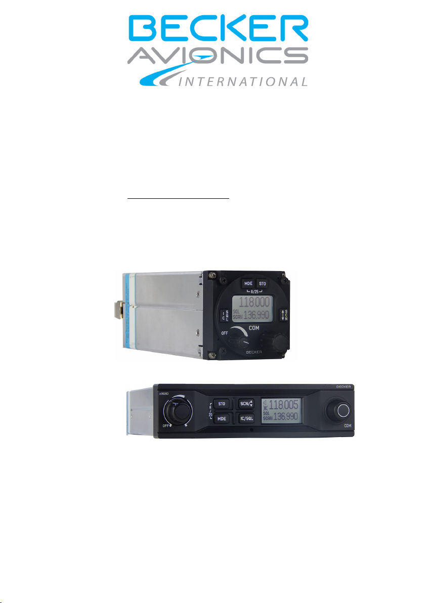
VHF Transceiver
Article-No.: 0638.420-071
AR6201, AR6203, RT6201, RCU6201
Software Versions:
from Software Version
SCI1050S305 Version 4.06
SCI1051S305 Version 2.06
Operating Instructions
http://www.becker-avionics.com • E-mail: info@becker-avionics.com
Issue 03 July 2015
Becker Avionics GmbH • Baden-Airpark B108
77836 Rheinmünster • Germany •
+49 (0) 7229 / 305-0 • Fax +49 (0) 7229 / 305-217

Operating Instructions
Table of Contents
Table of Contents ................................................................................................ 2
List of Abbreviations ........................................................................................... 3
Units ..................................................................................................................... 4
1. Introduction ................................................................................................. 5
1.1. General Safety Definitions ............................................................................ 5
1.2. Warranty Conditions ..................................................................................... 6
1.3. Conditions of Utilization ................................................................................ 6
1.3.1. Purpose of Equipment ................................................................. 6
1.3.2. Additional Conditions of Utilization .............................................. 6
1.4. Non Warranty Clause ................................................................................... 6
2. Operating Instructions ............................................................................... 7
2.1. Device Description ........................................................................................ 7
2.1.1. Device Assignment...................................................................... 7
2.1.2. Type Specification Label ............................................................. 8
2.1.3. Safety-Conscious Utilization ........................................................ 9
2.2. Controls and Indicators ............................................................................... 10
2.3. Start-Up ...................................................................................................... 12
2.4. Receive and Transmit Mode ....................................................................... 12
2.4.1. Receive Mode ........................................................................... 12
2.4.2. Transmit Mode .......................................................................... 12
2.5. Frequency Selection Modes ....................................................................... 13
2.5.1. Standard Mode .......................................................................... 14
2.5.2. Direct Tune Mode ...................................................................... 16
2.5.3. Channel Mode ........................................................................... 17
2.5.4. Frequency Storage Functions ................................................... 18
2.5.5. Automatic Storage Function ...................................................... 20
2.5.6. Scan Mode ................................................................................ 20
2.6. SQUELCH .................................................................................................. 21
2.7. RX Field Strength Indication ....................................................................... 22
2.8. Channel Spacing Mode .............................................................................. 22
2.9. Auxiliary Audio Input ................................................................................... 23
2.10. Intercom Operation ..................................................................................... 24
2.11. VOX & Speaker Operation .......................................................................... 26
2.12. Menus ......................................................................................................... 26
2.12.1. Intercom Menu .......................................................................... 26
2.12.2. Pilots Menu ............................................................................... 28
2.13. Warning and Failure Indications ................................................................. 30
3. Index .......................................................................................................... 32
2 VHF Transceiver Family 620X 0638.420-071 Issue 03 July 2015

Operating Instructions
List of Abbreviations
List of Abbreviations
FAA
Federal Aviation Administration
AC
Alternating Current
AF
Audio Frequency
AR
Airborne Radio
ATT
Attenuation
AUX
Auxiliary
AWG
American Wire Gauge
BNC
Bayonet Neill Concelman
CBIT
Continuous Built-In Test
CFG
Configuration
CH
Channel
CM
Chassis Module
COM
Communication
DC
Direct Current
EASA
European Aviation Safety Agency
EMI
Electro Magnetic Interference
ETSO
European Transmission System Operators
EUROCAE
European Organisation for Civil Aviation Equipment
GND
Ground (Aircraft Ground)
GPS
Global Positioning System
HMI
Human Machinery Interface
HIRF
High Intensity Radiated Fields
IC
Intercom
I&O
Installation & Operation
LCD
Liquid Crystal Display
MFD
Multi-Function Display
M&R
Maintenance & Repair
N/A
Not Applicable
NAV
Navigation
PBIT
Power-On Built In Test
PTT
Push To Talk
PWR
Power
RCU
Remote Control Unit
RSSI
Received Signal Strength Indication
0638.420-071 Issue 03 July 2015 VHF Transceiver Family 620X 3

Operating Instructions
List of Abbreviations
RT
Remote Transceiver
RX
Receive
SQL
Squelch
SPKR
Speaker (Loudspeaker)
SRC
Source
SW
Software
TSO
Technical Standard Order
TX
Transmit
VOX
Voice Operated IC Threshold
VHF
Very High Frequency
VDC
Voltage Direct Current
VSWR
Voltage Standing Wave Ratio
VU
Volume Unit
Units
V
Volt
mV
Millivolt
A
Ampere
mA
Milliampere
W
Watt
mW
Milliwatt
kHz
Kilohertz
MHz
Megahertz
s
Second
dBm
Power ratio in Decibel
dB
Decibel
Ohm (Ω)
Resistor
kg
Kilogram
°C
Degree Celsius
mm
Millimetre
cm
Centimetre
Units
4 VHF Transceiver Family 620X 0638.420-071 Issue 03 July 2015
Operating Instructions
General Safety Definitions
Indicates a hazardous situation which, if not avoided,
will result in death or serious injury.
Indicates a hazardous situation which, if not avoided,
could result in death or serious injury.
Indicates a hazardous situation which, if not avoided,
could result in minor or moderate injury.
Is used to address practices not related to physical
injury.
Safety instructions (or equivalent) signs indicate
specific safety-related instructions or procedures.
1. Introduction
Before use of the VHF Transceiver it is recommended to study this
instruction manual carefully because it contains safety as well as operating
instructions.
Include this manual to the documentation carried on board the aircraft.
For further descriptions we are using following terms for VHF transceivers,
VHF remote transceiver and remote control unit, instead writing their
complete model number.
620X in general for the device family
AR620X for: AR6201, AR6203 (Single Block Transceiver)
RT for: RT6201 (Remote Transceiver)
RCU for: RCU6201 (Remote Control Unit)
1.1. General Safety Definitions
0638.420-071 Issue 03 July 2015 VHF Transceiver Family 620X 5
Operating Instructions
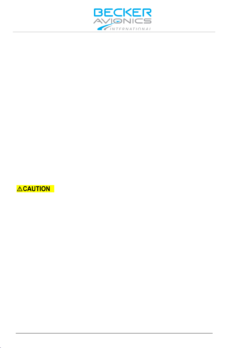
Non Warranty Clause
The user is responsible for protective covers and/or
damages to persons and electric accidents.
1.2. Warranty Conditions
User Conversions and Changes are Not Permitted
Any change made by the user excludes any liability on our part (excluding
updates for the navigation data base).
• The device must not be opened.
• Do not make any modifications to the device, except for those
described in the manual.
• Make connections to the inputs, outputs and interfaces only in
the manner described in the manual.
• Fix the devices according to the mounting instructions.
We cannot provide any guarantee for other mounting methods.
Conditions of Utilization
1.3.
General introductory notes
With this device you bought a product which was manufactured and tested
before delivery with the utmost care. Please take your time to read the
following notes which you ought to follow closely during installation and
operation. Unless, all claims under the warranty will become void and a
reduced service life or even damages must be expected.
additional safety measures in order to prevent
1.3.1.
Purpose of Equipment
The VHF transceiver enables voice communication in the very high
frequency band between 118.000 to 136.9916 MHz (radio communication
part of air-band) with a selectable channel spacing of 25 or 8.33 kHz.
1.3.2.
Additional Conditions of Utilization
Please refer to "Safety-Conscious Utilization", page 9.
1.4. Non Warranty Clause
We checked the contents of this publication for compliance with the
associated hard and software. We can, however, not exclude discrepancies
and do therefore not accept any liability for the exact compliance. The
information in this publication is regularly checked, necessary corrections
will be part of the subsequent publications.
6 VHF Transceiver Family 620X 0638.420-071 Issue 03 July 2015

Operating Instructions
Device Description
In this section the figures for illustrating display
operation modes.
from Software Version
2. Operating Instructions
The chapter "Operating Instructions" contains general information and
instructions to ensure safe operation of the VHF transceivers.
Device Description
2.1.
2.1.1.
Device Assignment
This manual is valid for the following devices:
• AR6201-(XX2)
• AR6203-(XX2)
• RT6201-(XX0) with RCU6201-(X12)
content mainly show transceivers working in
8.33/25 kHz mixed mode. Dedicated pictures for
25 kHz mode are not explicitly shown (they differ
only in number of digits for frequency).
The HMI actions described in this section can be
performed on primary controller or on optional
secondary controller RCU6201.
The following graphics of the display content show
the 8.33 kHz channel spacing for all possible
SCI1050S305 Version 4.06
SCI1051S305 Version 2.06
0638.420-071 Issue 03 July 2015 VHF Transceiver Family 620X 7

Operating Instructions
Device Description
PN:
XX2: white illumination colour on black panel
SN:
Unique number of the particular device
AN:
Article number
DoM:
Date of Manufacturing
Software:
Corresponding to the displayed version
Compliance and Certifications
Corresponding to the displayed text and logos
2.1.2. Type Plate
The device type is defined by the type plate (on the housing):
Figure 2-1: Type plate (example)
Explanation:
Type designation:
AR6201 = Single Block VHF Transceiver 58 mm (2¼ inch)
AR6203 = Single Block VHF Transceiver 160 mm (6.3 inch)
RT6201 = Remote VHF Transceiver
RCU6201 = Remote Control Unit 58 mm (2¼ inch)
Options:
0XX: 8.33/25 kHz channel spacing capability
1XX: 25 kHz channel spacing capability only
X1X: 10 W at 28 V
X2X: 6 W at 12 V
8 VHF Transceiver Family 620X 0638.420-071 Issue 03 July 2015

Operating Instructions
Device Description
Switch OFF the device before starting or shutting
down engines.
A voice communication test shall be performed
possible.
If the power supply voltage drops below 10 V the
2.1.3. Safety-Conscious Utilization
before starting the engine.
It should be noted that, if the communication test is
carried out close to a ground station, the results may
be positive even if the antenna cable is broken or
short-circuited. In such a case, at a distance of 5 to
10 km and above, communication might not be
• Speak always loud, clear and not too fast for optimal voice
communication.
• Keep the microphone always close to the lips otherwise a
special suppressing circuit in the VHF COM will not be capable
to suppress normal cabin noise.
• Use only microphones or headsets which are suitable for use
in an aircraft.
o In aircraft made of wood, synthetic materials or in gliders or
helicopters, incoming radiation can affect the integrated
amplifier of the microphone (feedback), noticeable in the
ground station by whistling and/or heavy distortion.
If the power supply voltage drops below the "Low Battery Threshold"
(default value is 10.5 V), the "LOW BATTERY" message will appear each
3 seconds in the lower part of the display.
system enters power saving mode:
• Speaker output of the transceiver is automatically
switched "OFF"
• Speaker sign will no longer be presented on LCD
display
• The pilot must use headphones to continue
listening.
0638.420-071 Issue 03 July 2015 VHF Transceiver Family 620X 9
Operating Instructions
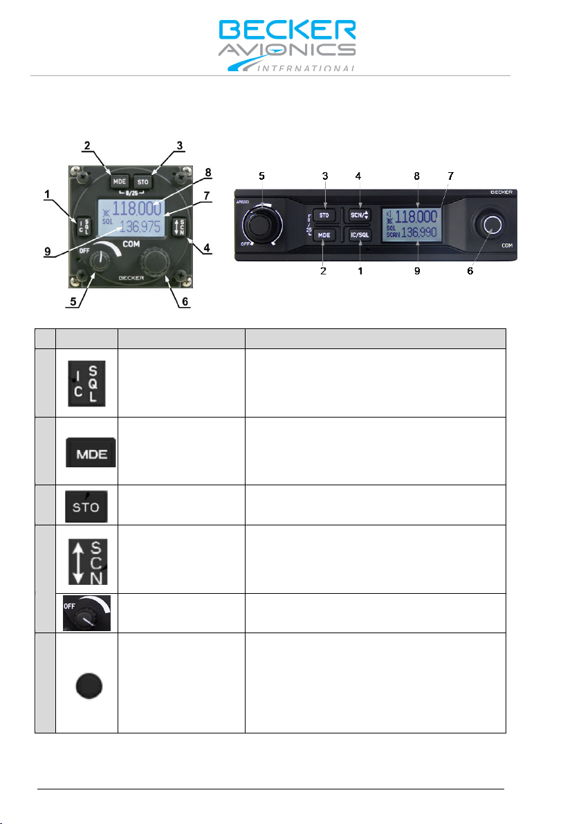
Controls and Indicators
AR620X and RCU6201
AR6203
Symbol
Description
Main Function
IC/SQL
"Short press" during normal operation
activates Intercom Menu.
MDE
"Short press" during normal operation
activates the pilots menu.
STO
"Short press" during normal operation
↨/SCN
"Short press" during standard mode, or
"Long press" activates scan mode.
Power ON/OFF,
Switches the transceiver ON/OFF and
Rotary encoder
Turning "ROTARY ENCODER" changes
an enter key.
2.2. Controls and Indicators
1
(Intercom/Squelch)
2
3
4
(Mode)
(Store)
(Exchange/SCAN)
Figure 2-2: Controls and indicators
toggles the RX -SQL ON/OFF.
"Long press" during normal operation
changes the frequency selection mode.
"Long press" during normal operation
activates storage procedure.
scan mode toggles between preset and
active frequency.
5
Volume Knob
adjusts volume level of received signal.
the settings of several parameters
6
(frequency, IC-volume, VOX, …).
Pushing the "ROTARY ENCODER"
toggles between the digits and acts as
10 VHF Transceiver Family 620X 0638.420-071 Issue 03 July 2015
 Loading...