

Page 1

Mode S Transponder
Installatio n and Operation
Manual DV15104.03
with ADS-B
BXT6500 Series
Issue 06 September 2018
Article-No. 0647.225 071
Becker Avionics GmbH • Baden-Airpark B108 • 77836 Rheinmünster • Germany
+49 (0) 7229 / 305-0 • Fax +49 (0) 7229 / 305-217
http://www.becker-avionics.com • E-mail: [email protected]
Page 2
Installation and Operation
Becker Avionics
Approved Production and Maintenance Organization
Contact data for:
Europe, Asia,
Becker Avionics GmbH
Contact data for:
America,
Becker Avionics Inc
Certificates see: http://www.becker-avionics.com/company-about/ →Certificates
Oceania and
Africa
Australia, Japan
Baden-Airpark B108
77836 Rheinmünster (Germany)
Tel.: + 49 (0) 7229 / 305-0
Fax: + 49 (0) 7229 / 305-217
Internet: www.becker -avionics.com
Email: info@becker-avionics.com
ustomer Service:
C
Email: [email protected]
Email: [email protected]
FAILURE OR IMPROPER SELECTION OR IMPROPER USE OF THE PRODUCTS DESCRIBED
HEREIN OR RELATED ITEMS CAN CAUSE DEATH, PERSONAL INJURY AND PROPERTY
DAMAGE.
This document and other information from Becker Avionics GmbH provide product or system options
for further investigation by users having technical knowledge.
The user is responsible for making the final selection of the system and components. The user has to
assure that all performance, endurance, maintenance, safety requirements of the application are met
and warnings be observed.
For this the user has to include all aspects of the application to be compliant with the applicable
industry standards and the requirements of the responsible aviation authority. The product
documentations from Becker Avionics GmbH have to be observed.
To the extent that Becker Avionics GmbH provide component or system options based upon data or
specifications provided by the user, the user is responsible for determining that such data and
specifications are suitable and sufficient for all applications and reasonably foreseeable uses of the
components or systems.
erm definition: User in the sense of user, installer, installation company.
T
WARNING - USER RESPONSIBILITY
2 BXT6500 Series DV15104.3 Issue 06 September 2018
Page 3
Becker Avionics
Installation and Operation
Preface
* design depends on variant
ear Customer,
D
hank you for purchasing a Becker Avionics product. We are pleased that you have chosen our
T
product and we are confident that it will meet your expectations.
For development and manufacturing of our product, the guidelines for highest quality and reliability
have been borne in m ind, supplemented by selection of high quality material, res ponsible production
and testing in accordance to the standards.
Our competent customer support department will respond on any technical question you may have.
Please do not hesitate to contact us at any time.
Transponder Design*
BXT65 Series
with EM module
with mounting tray and backshell
BXT65 Series
DV15104.3 Issue 06 September 2018 BXT6500 Series 3
Page 4

Installation and Operation
Becker Avionics
List of Effective Pages and Changes
Document: DV15104.03 / issue 06 Article Number 0647.255-071
Added: Descriptions about new variants and extended
Only technical relevant modifications are described in this table.
Cover Page 09/2018
Introduction 09/2018
Chapter 1 – 4 09/2018
Issue Page No.:
06
1-76 all Updated: Editorial adjustments.
--
all
--
--
2.7.8 Updated: Configuration example.
--
2.10 Added: Wiring examples.
--
--
--
--
--
Section /
Chapter
1.8.8
Description
temperature
U
pdated: Certification state.
--
--
--
--
--
--
© by Becker Avionics GmbH / all rights reserved
4 BXT6500 Series DV15104.3 Issue 06 September 2018
Page 5
Becker Avionics
Installation and Operation
Table of Contents
1 General Description .................................................................................................................... 13
1.1 Introduction.................................................................................................................................. 14
1.2 Purpose of Equipment ................................................................................................................. 15
1.3 Variants Overview ....................................................................................................................... 16
Variants Availability ........................................................................................................... 16
Software Status ................................................................................................................. 16
1.4 Associated Device s ..................................................................................................................... 16
1.5 Scope of Functionality ................................................................................................................. 17
Fixed and Non-Volatile Data ............................................................................................. 18
Diversity ............................................................................................................................ 18
Mode C, Mode S ............................................................................................................... 18
ADS-B (Automatic Dependent Surveillance-Broadcast) ................................................... 19
Supported Transponder Messages .................................................................................. 20
ADS-B Receiver Subset.................................................................................................... 20
Extended Temperature ..................................................................................................... 20
Interfaces .......................................................................................................................... 21
Built-In Test ....................................................................................................................... 21
Summary of Operational Description ................................................................................ 22
1.6 Safety-Conscious Utilization ....................................................................................................... 23
1.7 Restriction for Use ....................................................................................................................... 23
1.8 Technical Data ............................................................................................................................ 24
General Characteristics .................................................................................................... 24
Dimensions & Weight........................................................................................................ 26
Software ............................................................................................................................ 26
Hardware .......................................................................................................................... 26
Continued Airworthiness ................................................................................................... 26
Environmental Conditions - BXT6513............................................................................... 27
Environmental Conditions - BXT6553............................................................................... 29
Certifications ..................................................................................................................... 30
1.9 Order Code.................................................................................................................................. 32
BXT65 Series .................................................................................................................... 32
Accessories ....................................................................................................................... 32
2 Installation .................................................................................................................................... 35
2.1 Packaging, Transport, Storage ................................................................................................... 35
2.2 Device Assignment ..................................................................................................................... 36
Scope of Delivery .............................................................................................................. 36
Additional Required Equipment ........................................................................................ 36
Type Plate ......................................................................................................................... 37
Software Data Plate .......................................................................................................... 38
Meaning of Status LEDs ................................................................................................... 38
2.3 Mounting Requirements .............................................................................................................. 39
Mounting Distance ............................................................................................................ 40
Mounting Tray MT6533 ..................................................................................................... 40
Grounding ......................................................................................................................... 40
Cable Installation .............................................................................................................. 41
Recommended Crimp Tools ............................................................................................. 41
Antenna Cables ................................................................................................................ 42
Antenna Installation .......................................................................................................... 43
2.4 Dimensions.................................................................................................................................. 44
Transponder BXT65 Series .............................................................................................. 44
BXT65 Series with Mounting MT6533 .............................................................................. 45
BXT65 Series with Mounting MT6533 and Backshell BS6533-(100) ............................... 46
2.5 Electrical Installation ................................................................................................................... 47
Connector P1 .................................................................................................................... 47
Connector P2 .................................................................................................................... 49
Connector TOP, BOT (Antenna) ....................................................................................... 50
Connector USB ................................................................................................................. 51
Connector EM ................................................................................................................... 51
Service Connector (optional) ............................................................................................ 51
2.6 Interfaces..................................................................................................................................... 52
ARINC 429 Input Labels ................................................................................................... 52
DV15104.3 Issue 06 September 2018 BXT6500 Series 5
Page 6

Installation and Operation
Becker Avionics
ARINC 429 Output Labels ................................................................................................. 53
2.7 Configuration ............................................................................................................................... 54
General Architecture (example) ........................................................................................ 55
Single Device Installation .................................................................................................. 56
Dual Device Installation ..................................................................................................... 56
Device Installation Number ............................................................................................... 56
Data Source Configuration ................................................................................................ 56
Single Device Installation - Antenna Diversity .................................................................. 58
Single Device Installation – Single Antenna ..................................................................... 58
Dual Device Installation - Antenna Diversity ..................................................................... 59
Single Device Installation – Single Controller ................................................................... 59
Single Device Installation – Dual Controller (Selection by Switch) ................................... 60
Single Device Installation – Dual Controller (Burst Mode) ................................................ 60
Transmitter Disable ........................................................................................................... 61
GNSS Wiring ..................................................................................................................... 62
2.8 Configuration Data....................................................................................................................... 63
Configuration of BXT65XX with EM module ..................................................................... 63
Configuration of BXT65XX with internal memory.............................................................. 63
2.9 Software Update .......................................................................................................................... 64
PC Requirements .............................................................................................................. 64
Software Update Installation ............................................................................................. 64
2.10 Aircraft Wiring .............................................................................................................................. 66
BXT65XX (dual) with Control Device G7614 .................................................................... 66
BXT65XX with Control Device KFS 578A ......................................................................... 67
BXT65XX with GPS Device GTN750 ................................................................................ 67
BXT65XX (dual) with GPS Devices 1203C ....................................................................... 68
BXT6553 (dual) with Control & TCAS Device CTA-81A, TPA-81A .................................. 69
2.11 Post Installation Check ................................................................................................................ 70
Mechanical Installation and Wiring Check ........................................................................ 70
Power Supply .................................................................................................................... 70
Antenna Check .................................................................................................................. 70
Interference Check ............................................................................................................ 71
Mode S Ground Test ......................................................................................................... 71
Error / Failure Indication .................................................................................................... 71
3 Operating Instructions ................................................................................................................ 73
3.1 Device Description....................................................................................................................... 73
Device Assignment ........................................................................................................... 73
Packing, Transport, Storage ............................................................................................. 73
Scope of Delivery .............................................................................................................. 73
Type Plate ......................................................................................................................... 73
3.2 Start-up ........................................................................................................................................ 74
Built In Tests (BIT) ............................................................................................................ 74
Extended Temperature ..................................................................................................... 74
3.3 Operating ..................................................................................................................................... 74
Operating with OEM Controller ......................................................................................... 74
3.4 Read Out and Reset Error Flags ................................................................................................. 74
4 Index .............................................................................................................................................. 76
6 BXT6500 Series DV15104.3 Issue 06 September 2018
Page 7

Becker Avionics
Installation and Operation
List of Figures
Figure 1: Block Diagram – Mode S Transponder Concept (diversity example) ...................................................... 18
Figure 2: Type Plate (example) .............................................................................................................................. 37
Figure 3: Software Data Plate (example) ............................................................................................................... 38
Figure 4: BXT65 Series Mounting Area ................................................................................................................. 40
Figure 5: Antenna Installation (diversity) ................................................................................................................ 43
Figure 6: BXT65 Series .......................................................................................................................................... 44
Figure 7: BXT6565 Series with Mounting Tray MT6533 ........................................................................................ 45
Figure 8: BXT65 Series with Mounting Tray MT6533 and Backshell BS6533-(100) .............................................. 46
Figure 9: BXT65 series Connector Layout ............................................................................................................. 47
Figure 10: BS6533-(100) Connector Layout ......................................................................................................... 47
Figure 11: BS6533-(110) Connector Layout .......................................................................................................... 47
Figure 12: Service Connector inside the Aircraft .................................................................................................... 51
Figure 13: Wiring Diagram (diversity example, external memory) .......................................................................... 55
Figure 14: Single Device Installation ...................................................................................................................... 56
Figure 15: Dual Device Installation ........................................................................................................................ 56
Figure 16: Dual Device Installation, Data Source = External Memory Module ....................................................... 57
Figure 17: External Memory Module via Backshell ................................................................................................ 57
Figure 18: Single Device Installation, Data Source = Internal Memory .................................................................. 58
Figure 19: Single Device Installation - Antenna Diversity ....................................................................................... 58
Figure 20: Single Device Installation – Single Antenna .......................................................................................... 58
Figure 21: Dual Device Installation - Antenna Diversity ......................................................................................... 59
Figure 22: Single Device Installation - Single Controller ........................................................................................ 59
Figure 23: Single Device Installation – Dual Controller .......................................................................................... 60
Figure 24: Single Device Installation – Dual Controller (Burst Mode) .................................................................... 60
Figure 25: Single Device Installation - GNSS Wiring ............................................................................................. 62
Figure 26: Dual Device Installation - GNSS Wiring ................................................................................................ 62
Figure 27: Software Update – Aircraft Installation .................................................................................................. 64
Figure 28: Software Update – Laboratory Installation ............................................................................................ 65
Figure 29: Table – Ground Sensor Connection for Software Update (Laboratory) ................................................ 65
Figure 30: BXT65XX (dual) with Control Device G7614 (Gables) .......................................................................... 66
Figure 31: BXT65XX with Control Device KFS 578A (BendixKing) ........................................................................ 67
Figure 32: BXT65XX with GPS Device GTN750 (Garmin) ..................................................................................... 67
Figure 33: BXT65XX (dual) with GPS Devices 1203C (Freeflight)......................................................................... 68
Figure 34: BXT6553 (dual) with Control & TCAS Device CTA-81A, TPA-81A ....................................................... 69
DV15104.3 Issue 06 September 2018 BXT6500 Series 7
Page 8

Installation and Operation
Becker Avionics
List of Abbreviations
A/D
Analog to Digital
AA
Aircraft Address (24-bit ICAO)
AC
Advisory Circular
ACAS
Airborne Collision Avoidance System
ADC
Air Data Computer
ADLP
Airborne Data Link Processor
ADS-B
Automatic Dependent Surveillance-Broadcast
ARINC
Aeronautical Radio Inc.
ATC
Air Traffic Control
ATCRBS
Air Traffic Control Radar Beacon System
AWG
American Wire Gauge
BIT
Built-In Tests
CAN
Controller Area Network
CBIT
Continuous Built-In Test
DAC
Digital to Analog Converter
DC
Direct Current
DF
Downlink Format
DME
Distance Measurement Equipment
DSP
Digital Signal Processor
EEPROM
Electrically Erasable Programmable Read Only Memory
EM
External Memory
EMC
Electro-Magnetic Compatibility
EMI
Electro-Magnetic Interferences
ES
Extended Squitter
ESD
Electrostatic Sensitive Device
EUROCAE
European Organisation for Civil Aviation Equipment
FAA
Federal Aviation Administration
FCC
Flight Control Computer
FLS
Field Loadable Software
FMC
Flight Management Computer
FMS
Flight Management System
FRAM
Ferroelectric Random Access Memory
FRUIT
False Reply Uncoordinated in Time
GND
Ground (electrical)
GNSS
Global Navigation Satellite System
GPS
Global Positioning System
HF
High frequency
I/O
Inputs/Outputs
IBIT
Initiated Built-In Test
ICAO
International Civil Aviation Organization
List of Abbreviations
Alternating Current
Altitude Code
8 BXT6500 Series DV15104.3 Issue 06 September 2018
Page 9

Becker Avionics
Installation and Operation
List of Abbreviations
ID
Identifier
IF
Intermediate Frequency
II
Interrogation Identifier
IP
Internet Protocol
IRS
Inertial Reference System
LED
Light Emitting Diode
LVDS
Low Voltage Differential Signaling
MCP
Mode Control Panel
MSL
Mean Sea Level
NAV
Navigation
OEM
Original Equipment Manufacturer
PBIT
Power-On Built-In Test
PC
Personal Computer
PCB
Printed Circuit Board
PLD
Programmable Logic Device
RF
Radio Frequency
RFB
RF-Board
RTCA
Radio Technical Commission for Aeronautics Inc.
RX
Receiver, Receive
SDRAM
Synchronous Dynamic Random Access Memory
SI
Surveillance Identifier
SW
Software
TCAS
Traffic Alert and Collision Avoidance System
TF
TufLok®, self-locking screws and threads
TX
Transmitter
USB
Universal Serial Bus
VHF
Very High Frequency
DV15104.3 Issue 06 September 2018 BXT6500 Series 9
Page 10

Installation and Operation
Becker Avionics
Units
A
Ampere
mA
Milliampere
°C
Degree Celsius
cm
Centimeter
dBm
Power Ratio In Decibel, referenced to 1 mW
dB
Decibel
ft
Foot, feet
g
Gram
kg
Kilogram
kHz
Kilohertz
km/h
Kilometer Per Hour
kt
Knots
MHz
Megahertz
Mbps
Mega Bits Per Second
mm
Millimeter
Nm
Newton Meter
Ohm (Ω)
Resistance
s
Second
V
Volt
mV
Millivolt
W
Watt
mW
Milliwatt
"
Inch
Indicates a hazardous situation which, if not avoided, will result in death or
Indicates a hazardous situation which, if not avoided, could result in death or
Indicates a hazardous situation which, if not avoided, could result in minor or
Is used to address practices not related to physical injury.
Safety instructions (or equivalent) signs indicate specific safety-related
Units
General Safety Definitions
serious injury.
serious injury.
moderate injury.
instructions or procedures.
10 BXT6500 Series DV15104.3 Issue 06 September 2018
Page 11
Becker Avionics
Installation and Operation
Disposal
The packaging material is inflammable, if it is disposed of improperly by
The device(s) may be installed on an aircraft only by an approved aeronautical
The user is responsible for protective covers and/or additional safety measures in
burning, toxic fumes may develop.
This product contains materials that fall under the special disposal regulation, which corresponds to
the EC directive for dangerous disposal material. We recommend disposing of the respective materials
in accordance with the respectively valid environmental laws.
Dispose circuit boards via a technical waste dump which is allowed to take on e.g. electrolytic
aluminium capacitors. Do under no circumstances dump the circuit boards with normal waste dump.
Warranty Conditions
company (e.g. EASA Part 145) which shall also examine and verify the
installation.
User conversions and changes are not permitted.
Any change made by the u ser excludes any liabilit y on our part (excluding th e work described in th is
manual).
• The device must not be opened.
• Do not make any modifications to the device, except for those described in the manual.
• Make connections to the inputs, outputs and interfaces only in the manner described in
the manual.
• Fix the devices according to the mounting instructions.
We cannot provide any guarantee for other mounting methods.
Conditions of Utilization
General introductory notes
With this device you bought a product whic h was manufactured and tes ted before delivery with th e
utmost care.
Please take your tim e to read the follo wing notes which you ought to follo w closely during i nstallation
and operation.
Otherwise all claims under the warra nty will becom e void and a r educed ser vice l ife or even d amages
must be expected.
order to prevent damages to persons and electric accidents.
Additional Conditions of Utilization
Please refer to "Safety-Conscious Utilization", page 23.
Non-Warranty Clause
We checked the co nte nts o f this publication for com pli anc e with th e as soc ia ted h ar d a nd s of t ware. We
can, however, not exclude discrepancies and do therefore not accept any liability for the exact
compliance. The inf orm atio n in this p ublic ation is r egular ly chec ked, neces sar y co rrec tions wil l be part
of the subsequent publications.
DV15104.3 Issue 06 September 2018 BXT6500 Series 11
Page 12

Installation and Operation
Becker Avionics
Blank Page
12 BXT6500 Series DV15104.3 Issue 06 September 2018
Page 13
Becker Avionics
General Description
Introduction
1 General Description
In this chapter you can read about:
1.1 Introduction.................................................................................................................................. 14
1.2 Purpose of Equipment ................................................................................................................. 15
1.3 Variants Overview ....................................................................................................................... 16
Variants Availability ........................................................................................................... 16
Software Status ................................................................................................................. 16
1.4 Associated Device s ..................................................................................................................... 16
1.5 Scope of Functionality ................................................................................................................. 17
Fixed and Non-Volatile Data ............................................................................................. 18
Diversity ............................................................................................................................ 18
Mode C, Mode S ............................................................................................................... 18
ADS-B (Automatic Dependent Surveillance-Broadcast) ................................................... 19
Supported Transponder Messages .................................................................................. 20
ADS-B Receiver Subset.................................................................................................... 20
Extended Temperature ..................................................................................................... 20
Interfaces .......................................................................................................................... 21
1.5.8.1 ARINC 429 ................................................................................................................ 21
1.5.8.2 Logical Inputs/Outputs ............................................................................................... 21
1.5.8.3 Status and Control Ports ........................................................................................... 21
1.5.8.4 Internal and External Memory ................................................................................... 21
Built-In Test ....................................................................................................................... 21
Summary of Operational Description ................................................................................ 22
1.6 Safety-Conscious Utilization ....................................................................................................... 23
1.7 Restriction for Use ....................................................................................................................... 23
1.8 Technical Data ............................................................................................................................ 24
General Characteristics .................................................................................................... 24
Dimensions & Weight........................................................................................................ 26
Software ............................................................................................................................ 26
Hardware .......................................................................................................................... 26
Continued Airworthiness ................................................................................................... 26
Environmental Conditions - BXT6513............................................................................... 27
Environmental Conditions - BXT6553............................................................................... 29
Certifications ..................................................................................................................... 30
1.8.8.1 FCC Approval ............................................................................................................ 31
1.9 Order Code.................................................................................................................................. 32
BXT65 Series .................................................................................................................... 32
Accessories ....................................................................................................................... 32
This manual descr ibes the Becker remote controlled Mode S trans ponder of the BXT6500 s eries. T he
type plate on your device shows the part number for identification purposes (see "Type Plate",
page 37).
Before starting operati on of the device( s) please r ead this m anual caref ully, with par ticular atte ntion to
the description referring to your device(s).
DV15104.3 Issue 06 September 2018 BXT6500 Series 13
Page 14

General Description
Becker Avionics
DV15104.04
M&R
DV15104.03
I&O
General X X
Installation X X
Operation X X
Theory of Operation
X
N/A
Maintenance and Repair
X
N/A
Illustrated Parts List
X
N/A
Modification and Changes
X
N/A
Circuit Diagrams
X
N/A
Certifications X N/A
Attachments X N/A
Purpose of Equipment
1.1 Introduction
The technical information in this document applies to the described product "BXT65XX-(XXX)-(XX).
Details for variants please see "Variants Overview" page 16.
For further descriptions we are using the term "BXT65 series" or "BXT65XX".
If a description refers to only one product variants its full name, e.g. "BXT6513-(000)-(06)", will be
used.
The manuals "Maintenance and Repair" (M&R), "Installation and Operation (I&O) contain the f ol low ing
sections:
Section
14 BXT6500 Series DV15104.3 Issue 06 September 2018
Page 15

Becker Avionics
General Description
Purpose of Equipment
Actual generation of each ADS-B message type and data within each message
1.2 Purpose of Equipment
The BXT65XX transponder is designed as a r emote-controlle d single blo ck device and is intende d for
installation in aircraft avionics bay.
BXT65XX is a transponder which provides to other stations Mode A/C/S messages as well ADS-B
Extended Squitter functionality (ES).
BXT65XX is a remote-controlled device, which does not include a control panel. It can receive
commands and provides data through a set of standard interfaces.
Features:
• Control Interface ARINC 429.
• Mode A - in this mode, the 4096 character code is sent as a reply to interrogation from a
ground station.
• Mode C - in this mode, the encoded altitude is sent with 100 ft resolution.
• Mode S - interrogations are selective and Mode S transponders will respond to an
interrogation from ground stations or another aircraft with a reply containing its ICAO 24bit
address.
• ADS-B Broadcast-Only System, transmit:
o Airborne Position Message.
o Surface Position Message.
o Airborne Velocity Message.
o Aircraft Identification and C ateg ory Message.
o Aircraft Operational Status Mes sage.
o Extended Squitter Aircraft Status Message.
• ADS-B receiver subset captures Extended Squitter messages from aircraft and ground
vehicles (ADS-B IN functionality not certified).
• Single Antenna Operation (bottom antenna).
• Diversity - operation with two antennas (top and bottom)
o This is required for TCAS ǁ equipped aircraft.
o Additionally, in Europe for installation in aircraft with gross mass in excess of 5700 kg
or a maximum cruising true airspeed in excess of 250 kt (463 km/h).
• Support of the SI code (Surveillance Identifier).
• Elementary surveillance (ELS) and enhanced surveillance (EHS).
• Data link capability.
• GPS receiver connection capability.
• Selftests (BITs) are integrated in the transponder.
depends on availability of navigation data and GPS capabilities.
Actual provision of ELS and EHS data depends of availability of these data from
external equipment and configuration.
DV15104.3 Issue 06 September 2018 BXT6500 Series 15
Page 16
General Description
Becker Avionics
B
XT
65
XX
- (0XX)
- ( )
Identifier
Modification Index
Model
6513 = Transponder
6553
extended
000 – Diversity
Extended
Design Assurance
BXT6513-(000)
x
C
BXT6513-(010)
C
BXT6513-(020)
x x
C
BXT6553-(000)
x x
B
Manufacturer
Device
Function
BendixKing
KFS 578A
Control Device
Gables
G7614
Control Device
Freeflight
1201
GPS
Freeflight
1203C
GPS
Garmin
GTN750
GPS
Genesys
GPS-WAAS Rx
GPS
Associated Devices
1.3 Variants Overview
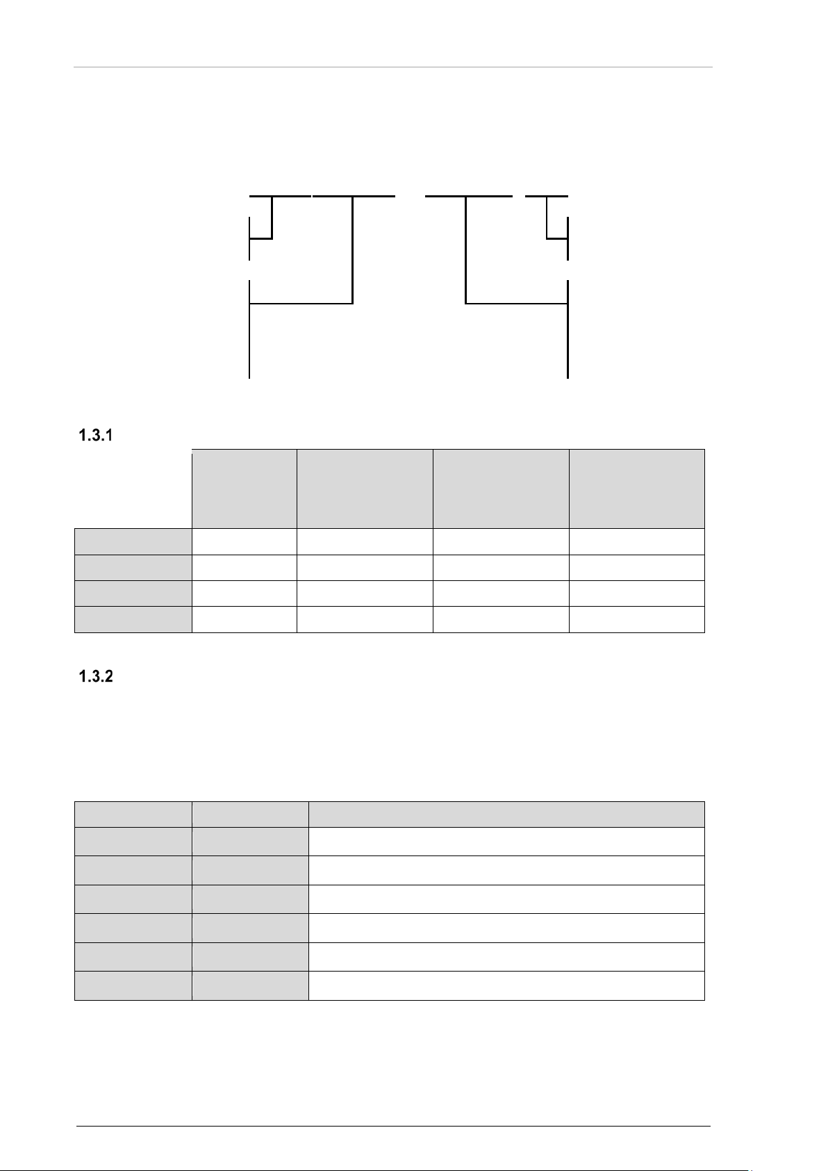
Within the part number, the meaning of "XX-(0XX)-()" is:
= Transponder+
temperature range
Variant s Availability
Diversity
sCloaking
(Mode S
disable option)
Softw are Status
Details please see "Software Data Plate", page 38.
1.4 Associated Devices
Temperature
(-55 °C)
010 – Single antenna
020 = Mode S
disable option
Level
Following devices can operate with BXT65 series. For wiring diagrams please see "Aircraft Wiring" page 66.
For other devices please contact Becker Avionics.
This manual describes the BX T65 series from Beck er Avionics. For ot her devices please r efer to the
corresponding manuals.
16 BXT6500 Series DV15104.3 Issue 06 September 2018
Page 17

Becker Avionics
General Description
1.5 Scope of Functionality
BXT6513-(0XX):
• Operates on radar frequencies; receiving ground radar and ACAS interrogations and
replies via its transmitter with coded pulse packages on 1090 MHz.
• A special position identification pulse (SPI) can be added for a period of 18 seconds to
each pulse package after activation of the dedicated discrete signal input on the device.
• Meets Mode S Enhanced Surveillance (EHS) requirements.
o EHS parameters require additional interface with other aircraft systems and the
BXT6513-(0XX).
o Aircraft that can provide the list of eight Downlink Aircraft Parameters (DAPs) listed in
BDS registers 4.0, 5.0 and 6.0 are considered to be Mode S EHS capable.
o Aircraft that cannot provide these parameters will be considered as not EHS capable.
BXT6513-(000):
• Provides downlink of aircraft information and supporting 2 antennas; one shall be installed
on top side, and the other on the bottom side of the aircraft fuselage (detailed type
description see "Type Plate", page 37).
BXT6513-(010):
• Provides downlink of aircraft information and supporting a single antenna which shall be
installed on the bottom side of the aircraft fuselage (detailed type description see "Type
Plate", page 37).
BXT6513-(020):
• Is a transponder which has in addition to the BXT6513-(000) also the possibility to switch
to Mode A/C only. If the transponder is switched to this Mode it does not supply
Mode S replies.
BXT6553-(000):
• Is a transponder which has in addition to the BXT6513-(000) an extended temperature
range and its Software and Complex Hard ware is desig ned ac c ordin g to
Design Assurance Level B.
Scope of Functionality
DV15104.3 Issue 06 September 2018 BXT6500 Series 17
Page 18

General Description
Becker Avionics
Interfaces and Signal Conditioning
Antenna
switch
Interrogation
processing/
reply
assembly
1090 MHz
Transmitter
1090 MHz
Receiver
(top antenna)
1090 MHz
Receiver
(bottom antenna)
Supply
Control
Avionic data
Configuration
&
Maintenance
Status
ADLP
Antennas
Scope of Functionality
Fixed and Non-Volatile Data
The BXT65XX conf iguration is stored in a non-vol atile memory. There are two possibilities where to
store configuration data:
• Use the internal memory.
• Use the external memory module EM6100.
The selection of eq uipm ent conf iguratio n so urce is done by har dwar e conf igura tion (s ee " Data Sourc e
Configuration", page 56).
Diversity
Antenna diversity reduc e the potential for antenn a "shading" and helps to prevent target drop out in
each situation.
BXT65XX-(000) is capab le to operate with two antennas (top and bottom), required f or installation in
aircraft with gross mass in excess of 5700 k g or a m aximum cruising true airspee d in ex c ess of 250 kt
(463 km/h).
Mode C, Mode S
Mode C - in this mode, the encoded altitude is sent in addition to the mode A reply.
• Mode C - in this mode, the encoded altitude is sent with 100 ft resolution.
o Data range for 100 ft resolution: -1000…126 750 ft.
BXT65 series as Mode S transponder is an airborne part of Mode S Secondary Surveillance Radar
system which detects ground interrogations arriving at 1030 MHz signal frequency, processes them
and generates responses at 1090 MHz signal frequency.
o The altitude information must be delivered from an external device.
• Mode S - interrogations are selective and Mode S transponders will respond to an
interrogation from ground stations or another aircraft with a reply containing its
ICAO 24 bit address.
o Data range for 25 ft resolution: -1000…50 187 ft.
o Data range for 100 ft resolution: -1000…126 750 ft.
o The altitude information must be delivered from an external device.
18 BXT6500 Series DV15104.3 Issue 06 September 2018
Figure 1: Block Diagram – Mode S Transponder Concept (diversity example)
Page 19

Becker Avionics
General Description
Scope of Functionality
ADS-B (Aut om at ic Dependent Surveillance-Broadcast)
ADS-B is a GPS based tec hno logy to define and provide aircraf t r ele vant dat a . T o s uppor t AD S-B Out,
the aircraft needs a cert ified GPS recei ver as the position s ource, and this device to send the AD S-B
data. This data can be received by other air- and ground stations.
The Automatic Dependent Surveillance-Broadcast Out (ADS-B Out) function provides position,
velocity and status data on the transponder for br oadcasting as extende d squitter (ES). W hen data is
available, it is transmitted at specific periods and enable other participants to determine current
position, velocity and status of the aircraft without interrogation.
BXT65 series is an ADS-B class B1 or B1S (aircraft broadcast only) Mode S transponder capable for
automatically sending out ADS-B data like:
• (BDS 0,5) Airborne Position Messag e.
o Special Position Identification (SPI).
o Emergency Indicator.
o Barometric Altitude.
o Quality Indicator (NIC).
o Latitude (Airborne Position).
o Longitude (Airborne Position).
• (BDS 0,6) Surface Position Message.
o Quality Indicator (NIC).
o Latitude (Surface Position).
o Longitude (Surface Position).
o Surface Ground Speed.
o Surface Ground Track.
• (BDS 0,8) Aircraft ID and Category Message.
o Aircraft Identification & Category.
• (BDS 0,9) Airborne Velocity.
o Airborne Ground Velocity.
o Geometric to Barometric Altitude Difference.
o Geometric Vertical Speed.
• (BDS 6,1) Emergency/Prior it y Status .
o Squawk Code.
o Emergency Status.
• (BDS 6,5) Aircraft Operational Sta tus Mes sage, Airb or ne and Sur f ace.
o Quality Indicator (NACp, NACv and GVA).
o Quality Indicator (SIL and SDA).
o Version Indicator.
o Surface Length/Width.
o Surface Antenna Offset.
DV15104.3 Issue 06 September 2018 BXT6500 Series 19
Page 20

General Description
Becker Avionics
Processing received messages into a track file containing information about
Scope of Functionality
Supported Transponder Messages
BXT65 series supports the following Binary Data Selector (BDS) registers.
General Mode S Registers:
• (BDS 1,0) Data Link Capability Repor t.
• (BDS 1,7) Common Usage GICB Capability Report.
• (BDS 1,8 to 1,C) Mode S Specific Services GICB Capability Report.
Elementary Surveillance Registers:
• (BDS 2,0) Flight ID.
• (BDS 2,1) Aircraft Registration.
Enhanced Surveillance Registers:
• (BDS 4,0) Selected Vertical Intention Report (except Vertical Mode).
• (BDS 5,0) Track and Turn Report.
• (BDS 6,0) Heading and Speed Report.
Extended Squitter/ADS-B Registers:
• (BDS 0,5) Airborne Position Message.
• (BDS 0,6) Surface Position Message.
• (BDS 0,8) Aircraft ID and Category Message.
• (BDS 0,9) Airborne Velocit y.
• (BDS 6,1) Emergency/Priority Status.
• (BDS 6,5) Aircraft Operational Stat us Mes sage, A ir borne .
• (BDS 6,5) Aircraft Operational Status Message, Surf ac e.
ADS-B Receiver Subset
The ADS-B receiver subs et operat es at 1090 MH z ban d and det ects , captures an d decod es Exte nded
Squitter messages from aircraft and ground vehicles (DF=17, 18 and optional 19 are supported).
Received ADS-B messages are formed in message reports and transmitted through LAN interface.
This ADS-B IN functionality is not part of the certification.
surrounding aircraft and ground vehicles is not implemented yet.
Extended Temperature
The BXT6553 variant provides features like:
• Extended temperature range.
• Low operating temperature is extended to -55 °C.
• It achieves ED-14G/DO-160G Section 4 Category F2.
• It is intended for installation in non-pressurized and non-controlled temperature locations
on an aircraft that is operated at altitudes up to 55 000 ft.
20 BXT6500 Series DV15104.3 Issue 06 September 2018
Page 21

Becker Avionics
General Description
Scope of Functionality
We recommend the usage of the External Memory module EM6100 as data
Interfaces
1.5.8.1 ARINC 429
The ARINC 429 specification is a standard how avionics equipment and systems communicate on
aircraft. The specification defines:
• Electrical characteristics.
• Word structures.
• Protocol for bus communication.
Electrical and data form at charac terist ics ar e defined f or a two-wire serial bus with one transm itter and
up to 20 receivers. This simple architecture provides a highly reliable transfer of data. The bus is
capable of operating at a speed of 12.5 kbit/s (low speed) or 100 kbit/s (high speed).
For detailed information about ARINC 429 specifications please refer to: www.arinc.com
.
Copyright Note ARINC: ARINC429 is a privately copy written specification developed to provide
interchange ability and interoperability of line replaceable devices (LRUs) in commercial aircraft.
ARINC stands for Aeronautical Radio, Inc.
1.5.8.2 Logical Inputs/Outputs
The hardware design of BXT65 series provides a subset of inputs and outputs required for
transponder operation.
1.5.8.3 Status and Control Ports
The hardware design of BXT65 series provides a subset of ports for provide information about
transponder status and for controlling.
1.5.8.4 Internal and External Memory
An internal or exter nal memory is used as c onfiguration data sourc e, saving aircraft data installation
and configuration data.
On start-up BXT65 series reads from this non-volatile memory configuration data which include
parameters specif ic to the actual airc raft and inst allation. T ypically, an ex ternal m emory (EM) is used.
If BXT65 series is repl aced e.g. for maintenance, so the new BXT65XX can be connec ted with the
external memory modul e in this way it is guarante ed that all relevant data is available for fas t & easy
exchange.
source.
Built-In Tes t
BXT65 series has advanced Built-In-Test. It monitors most of internal circuits against failures.
DV15104.3 Issue 06 September 2018 BXT6500 Series 21
Page 22

General Description
Becker Avionics
Scope of Functionality
BXT65XX-(0XX)
Specifications
Transmit Frequency
1090 MHz ±1 MHz
Modulation (Mode A/C)
PAM (Pulse Amplitude Modulation)
Modulation (Mode S)
DPSK (Differential Phase Shift Keying)
Bandwidth (Mode A/C)
8.4 MHz
Bandwidth (Mode S)
8 MHz
Data rate
Depends on the number of interrogations of the ground
Summary of Operational Description
• The BXT65 series is continuously monitoring incoming RF signals at frequency of
1030 MHz for radar interrogations.
• When an interrogation is detected and dec od ed, the tr a nspond er proces s es it and
generates a reply which is transmitted at radio frequency of 1090 MHz.
• Transponder replies allow an ATC ground station to locate, identify and track an aircraft.
• With use of interrogations and replies it is also possible to send data to and from an
aircraft.
• The device provides transponder functionality for Mode A/C and Mode S operation.
• The BXT65 series periodically transmits squitter, which are transmitted independent on
interrogations from ground stations.
Two types of squitter are generated:
• An acquisition squitter carries 56-bit data allowing acquisition of the aircraft is transmitted
approximately once per second.
• Extended squitter carries 112 bits of data and are used by ADS-B transmitter function.
station
22 BXT6500 Series DV15104.3 Issue 06 September 2018
Page 23
Becker Avionics
General Description
1.6 Safety-Conscious Utilization
The device(s) may be installed on an aircraft only by an approved aeronautical
Excessive pulses on the DC bus of the aircraft may cause damage on electrical
It is the responsibility of the installer to ensure the ADS-B Out system is
For safe operation of the product the following notes have to be observed:
company (e.g. EASA Part 145) which shall also examine and verify the
installation.
• The installation of the BXT65 series into an aircraft may be carried out only
by an authorized installation company. The country regulations always have
to be observed.
• Use the product only within the specified conditions, see "Technical Data"
page 24.
• C irc uit breaker:
o Use the recommended fuses in the power line to protect the
application, see "T ec hnica l Data", page 24.
circuits of any installed instrument.
compliant with current national regulations e.g. AC 20-165B and to ensure
compatibility between the BXT65 series and the ADS-B Out position source
equipment.
Restriction for Use
1.7 Restriction for Use
• BXT65 series is to be used inside the declared limits.
DV15104.3 Issue 06 September 2018 BXT6500 Series 23
Page 24

General Description
Becker Avionics
Technical Data
BXT65 series
Specifications
Supply voltage
BXT6513: 28 VDC (18.0...32.2 VDC)
Emergency voltage
BXT6513: 18 VDC min.
Current/Power consumption
BXT6513
Typical current
Typical power
Max. current
operation
0.5 A
14 W
0.95 A
BXT6553
Typical current
Typical power
Max. current
operation
0.5 A
14 W
0.95 A
warmup, no operation
2.0 A
56 W
2.5 A
warmup + operation
2.4 A
67 W
3.4 A
Recommended external fuse protection
BXT6513: 3 A
RF port
Impedance
50 Ω
Transmitter frequency
1090 ± 1 MHz
Transmitter power
> 125 W at antenna terminal
Receiver frequency
1030 MHz
Mode A/C sensitivity
-73 ± 4 dBm at antenna terminal
Mode S sensitivity
-74 ± 3 dBm at antenna terminal
Interrogations - Mode
Mode A, C, A/S All Call, C/S All Call,
Reply rate capability
Mode A/C
Continuous: 500 replies per second
Mode S
60 long replies per second
Squitter
Short (56 bits): Acquisition
Long (112 bits): Identification and Category
1.8 Technical Data
General Characteristics
BXT6553: 28 VDC (22.0...32.2 VDC)
BXT6553: 22 VDC min.
consumption
@ 28 V
consumption
@ 28 V
consumption
@ 28 V
consumption
@ 28 V
BXT6553: 5 A
(> 250 W at transponder output)
consumption
consumption
24 BXT6500 Series DV15104.3 Issue 06 September 2018
Mode S (DF=0, 4, 5, 11, 16, 20, 21)
Peak (100 ms): 1200 replies per second
12 short and 6 long replies in 100 ms
4 short and 4 long replies in 25 ms
2 short and 2 long replies in 1.6 ms
Airborne Posit io n
Page 25

Becker Avionics
General Description
Technical Data
BXT65 series
Specifications
Airborne Veloc ity
Interface
Control Interface
ARINC 718A, 3x ARINC 429 In
Air Data Computer
ARINC 706, 2x ARINC 429 In
ADLP
ARINC 718A, 1x ARINC 429 In, 1x ARINC 429 Out
FCC
ARINC 701, 1x ARINC 429 In
FMC
ARINC 702, 1x ARINC 429 In
IRS
ARINC 704, 1x ARINC 429 In
GNSS
ARINC 743A, 1x ARINC 429, 1x Time Mark (differential)
TCAS
ARINC 735B, 1x ARINC 429 In, 1x ARINC 429 Out
Radio Altimeter
ARINC 707, 1x ARINC 429 In
Data concentrator
2x ARINC 429 In
Data output
ARINC 718A, 2x ARINC 429 Out
Field Loadable Software
ARINC 826, 1x CANbus, 1x Discrete In
Mutual Suppression
ARINC 718A
IDENT
1x Discrete In
Standby
1x Discrete In
Control Port select
1x Discrete In
ADC select
1x Discrete In
Weight on Wheels
1x Discrete In
Ext. Squitter disable
1x Discrete In
Burst Mode
1x Discrete In
Reply indication
1x Discrete Out
Status
3x Discrete Out
Maintenance
1x USB (front panel)
ADS-B IN data
1x Ethernet
Surface Position
Aircraft Operational Status
Extended Squitter Aircraft Status
or RS232/RS422
DV15104.3 Issue 06 September 2018 BXT6500 Series 25
Page 26
General Description
Becker Avionics
Technical Data
BXT65 series
Specifications
BXT65XX only (HxWxD)
171 x 47.4 x 276 mm (6.73 x 1.87 x 10.87 in)
BXT65XX depth with EM module
310 mm (12.21 in)
BXT65XX with mounting + backshell
172.5 x 52.4 x 331 mm (6.79 x 2.06 x 13.03 in)
Weight
Transponder BXT6513
≤ 1.6 kg (3.53 lb)
Mounting tray MT6533-(000)
≤ 0.50 kg (1.10 lb)
Backshell BS6533-(100)
≤ 0.3 kg (0.66 lb)
External memory module EM6100
≤ 0.018 kg (0.04 lb)
Dimensions & Weight
(HxWxD)
Transponder BXT6553
≤ 2.0 kg (4.4 lb)
Software
BXT6513:
The "Failure Condition Classification" given by the relevant ETSO for this class of devices is MAJOR.
The "Design Assurance Level" (DAL) of BXT6513 according DO-178C is:
Level C
BXT6553:
The "Failure Condition Classification" given by the relevant ETSO for this class of devices is MAJOR.
The "Design Assurance Level" (DAL) of BXT6553 according DO-178C is:
Level B
Hardware
BXT6513:
The Complex Electronic Hardware (CEH) included into BXT6513-(0XX) has been designed in
accordance with EUROCAE/RTCA Document ED-80/DO-254; "Design Assurance Guidance for
Airborne Electronic Hardware" and satisfy criteria of:
Hardware Assurance Level (HAL) C
BXT6553:
The Complex Electr onic Hardware (CEH) included into BXT6553 has been d esigned in accordance
with EUROCAE/RTCA Document ED-80/DO-254; "Design Assurance Guidance for Airborne
Electronic Hardware" and satisfy criteria of:
Hardware Assurance Level (HAL) B
Continued Airworthiness
For continued airworthiness please do a check and obey the local regulations.
• For Germany:
o Do a functional test of the device(s) every two years.
We recommend a ramp tester as test equipment.
26 BXT6500 Series DV15104.3 Issue 06 September 2018
Page 27

Becker Avionics
General Description
Technical Data
Characteristics
Section
Cat.
Condition
Temperature and Altitude
4
B2
Ground Survival Low Temperature
4.5.1
B2
-55 °C
Operating Low Temperature
4.5.2
B2
-45 °C
Ground Survival High Temperature
4.5.3
B2
+85 °C
Short-Time Operating High T emperature
4.5.3
B2
+70 °C
Operating High Temperature
4.5.4
B2
+70 °C
In-flight Loss of Cooling
4.5.5
Z
No cooling required
Altitude
4.6.1
F1
55 000 ft
Decompression
4.6.2
X
No test performed
Overpressure
4.6.3
X
No test performed
Non-temperature controlled or partially
Humidity
6
B
Severe humidity environment
Tested for standard operational shock and
Standard vibrations test:
Robust vibrations test: Helicopters with
Explosion Proofness
9
X
No test performed
Water Proofness
10
X
No test performed
Fluids Susceptibility
11
X
No test performed
Sand and Dust
12
X
No test performed
Fungus Resistance Compliance performed
Salt Spray
14
X
No test performed
Deflection for magnetic compass is ≤ 1°, if
Environmental Conditions - BXT6513
BXT6513-(0XX) was tested in accordance with ED-14G/DO-160G under consideration of listed
environmental categories and conditions:
Temperature Variation 5 B
Operational Shocks and Crash Safety 7 B
Vibration 8 SMB2
8 U2FF1
Fungus Resistance 13 F
temperature controlled internal sections of
the aircraft
crash safety
• s ine vibr ati on cur ve M
• random vibration curve B2
unknown frequencies, Zone 1a and 2:
fuselage, instrument panel, console and
equipment rack
by Analysis
Magnetic Effect 15 Z
DV15104.3 Issue 06 September 2018 BXT6500 Series 27
device is installed with a distance of
≤ 0.3 m
Page 28

General Description
Becker Avionics
Characteristics
Section
Cat.
Condition
28 VDC equipment installed in aircraft
DC current ripple
16
X
No test performed
Inrush current
16
X
No test performed
High degree of protection against damage
28 VDC equipment with no battery or
Equipment for which interference-free
Compliant to high intensity radiated fields
Located in areas where apertures are
Lightning Induced Transients
Pin test waveform set A, level 3. Cable
Lightning Direct Effect s
23
X
No test performed
Icing
24
X
No test performed
Installed, repaired or operated in an
Fire, Flammability
26
X
No test performed
Technical Data
Power Input 16 B
supplied with engine-driven
alternator/rectifiers or DC generators
where a battery of significant capacity is
floating on DC bus all the time
Voltage Spike 17 A
Audio Freq. Conducted Susceptibility 18 Z
by voltage spikes
battery small compared with the capacity
of the DC generator
Induced Signal Susceptibility 19 CCX
operation is required; installed on aircraft
where severe coupling occurs due to long
wire runs
Radio Frequency Susceptibility 20 RR
Emission of Radio Frequency Energy 21 M
associated with the normal environment
significant and not directly in view of radio
receiver’s antenna
Susceptibility
Electrostatic Discharge 25 A
22 A3E3XX
bundle test waveform set E, level 3
aerospace environm ent
BXT6513-(0XX) is fulfilling the related requirements of AC20-158A and AC20-136B.
28 BXT6500 Series DV15104.3 Issue 06 September 2018
Page 29

Becker Avionics
General Description
Technical Data
Characteristics
Section
Cat.
Condition
Temperature and Altitude
4
F2
Ground Survival Low Temperature
4.5.1
F2
-55 °C
Operating Low Temperature
4.5.2
F2
-55 °C
Ground Survival High Temperature
4.5.3
F2
+85 °C
Short-Time Operating High T emperature
4.5.3
F2
+70 °C
Operating High Temperature
4.5.4
F2
+70 °C
In-flight Loss of Cooling
4.5.5
Z
No cooling required
Altitude
4.6.1
F1
55 000 ft
Decompression
4.6.2
X
No test performed
Overpressure
4.6.3
X
No test performed
Non-temperature controlled or partially
Humidity
6
B
Severe humidity environment
Tested for standard operational shock and
Standard vibrations test:
Robust vibrations test: Helicopters with
Explosion Proofness
9
E
Waterproofness
10
X
No test performed
Fluids Susceptibility
11
X
No test performed
Sand and Dust
12
X
No test performed
Fungus Resistance Compliance performed
Salt Spray
14
X
No test performed
Deflection for magnetic compass is ≤ 1°, if
28 VDC equipment installed in aircraft
DC current ripple
16
X
No test performed
Inrush current
16
X
No test performed
High degree of protection against damage
28 VDC equipment with no battery or
Environmental Conditions - BXT6553
BXT6553-(000) was tested in accordance with ED-14G/DO-160G under consideration of listed
environmental categories and conditions:
Temperature Variation 5 B
Operational Shocks and Crash Safety 7 B
Vibration 8 SMB2
8 U2FF1
Fungus Resistance 13 F
temperature controlled internal sections of
the aircraft
crash safety
• Sine vibration curve M
• Random vibration curve B2
unknown frequencies, Zone 1a and 2:
fuselage, instrument panel, console and
equipment rack
by Analysis
Magnetic Effect 15 Z
Power Input 16 B
Voltage Spike 17 A
Audio Freq. Conducted Susceptibility 18 Z
DV15104.3 Issue 06 September 2018 BXT6500 Series 29
device is installed with a distance of
≤ 0.3 m
supplied with engine-driven
alternator/rectifiers or DC generators
where a battery of significant capacity is
floating on DC bus all the time
by voltage spikes
battery small compared with the capacity
of the DC generator
Page 30

General Description
Becker Avionics
Technical Data
Characteristics
Section
Cat.
Condition
Equipment for which interference-free
Compliant to high intensity radiated fields
Located in areas where apertures are
Lightning Induced Transients
Pin test waveform set A, level 3. Cable
Lightning Direct Effect s
23
X
No test performed
Icing
24
X
No test performed
Installed, repaired or operated in an
Fire, Flammability
26
X
No test performed
Part Number
EAS A Appr o v a l
BXT6513-(000)-()
EASA.21O.10061875 Rev. A
BXT6513-(010)-()
EASA.21O.10061875 Rev. A
BXT6513-(020)-()
pending
BXT6553-(000)-()
pending
Specifications
ETSO
C112e – Level 2 adens, Class 1
ED12C / DO178C
BXT6513: DAL C
ED80 / DO-254
BXT6513: DAL C
ICAO
Annex 10, Vol IV
MOPS
EUROCAE ED-14G/RTCA/DO-160G, EUROCAE ED-73E,
Induced Signal Susceptibility 19 CCX
operation is required; installed on aircraft
where severe coupling occurs due to long
wire runs
Radio Frequency Susceptibility 20 RR
Emission of Radio Frequency Energy 21 M
associated with the normal environment
significant and not directly in view of radio
receiver’s antenna
Susceptibility
Electrostatic Discharge 25 A
22 A3E3XX
bundle test waveform set E, level 3
aerospace environm ent
BXT6553-(000) is fulfilling the related requirements of AC20-158A and AC20-136B.
Certifications
The remote-control led Mod e S Transponder BXT65XX is certified.
BXT65 series meets the requirements of:
(single antenna: Level 2 ens)
C166b Class B1
(single antenna: Class B1S)
BXT6553: DAL B
BXT6553: DAL B
EUROCAE ED-102A
30 BXT6500 Series DV15104.3 Issue 06 September 2018
Page 31

Becker Avionics
General Description
Technical Data
1.8.8.1 FCC Approval
Radiofrequency radiation exposure information:
This equipment com plies with FC C rad iatio n exp osure lim its set f orth f or an uncontr olled enviro nm ent.
This equipment should be installed and operated with minimum distance of 50 cm between the
radiator and your body.
This transmitter must not be co-located or operating in conjunction with any other antenna or
transmitter.
NOTE:
This equipment has been tested and found to comply with the limits for a Class A digital device,
pursuant to Part 15 of the FCC Rules. These limits are designed to provide reasonable protection
against harmful interference when the equipment is operated in a commercial environment. This
equipment generates, uses, and can radiate ra dio frequency energ y and, if not installed an d used in
accordance with the instruction manual, may cause harmful interference to radio communications.
Operation of this e quipment in a residential ar ea is likel y to cause har mful interfe rence in which c ase
the user will be required to correct the interference at his own expense.
NOTE:
This device complies with Part 15 of the FCC Rules [and with Industry Canada licence-exempt
RSS standard(s)].
Operation is subject to the following two conditions:
• This device may not cause harmful interference.
• This device must accept any interference received, including interference that may cause
undesired operation.
NOTE:
Changes or modifications made to this equipment not expressl y approved by Becker Avionics may
void the FCC authorization to operate this equ ipment.
DV15104.3 Issue 06 September 2018 BXT6500 Series 31
Page 32

General Description
Becker Avionics
Qty
Transponder
1
BXT6513-(000)-():
Article No. 0645.141-915
1
BXT6513-(010)-():
Article No. 0649.732-915
1
BXT6513-(020)-():
Article No. 0657.948-915
1
BXT6553-(000)-():
Article No. 0652.414-915
Qty
External Memory
1
EM6100-(000) External Memory for BXT6513
Article-No. 0608.270-921
1
EM6100-(010) External Memory-Extended Temperature for
Article-No. 0661.015-921
Qty
Software
1
EMP6100-BXT, External Memory Programming Set
Article-No. 0649.961-954
1
FLS6500-BXT Kit, Field Loadable Software Kit BXT65 Series
Article-No. 0659.517-919
1
SSW6500-BXT, Service Software
Article-No. 0659.495-919
Qty
Mounting Equipment
1
Mounting Tray MT6533-(000)
Article-No. 0635.952-264
1
Backshell BS6533-(100) for MT6533
Article-No. 0645.168-284
1
Backshell BS6533-(110) single antenna for MT6533
Article-No. 0649.767-284
Qty
Antenna
-
BXT65XX-(0XX) accept all types of transponder antennas.
Order Code
1.9 Order Code
BXT65 Series
XPDR (class1, Level 2 adens) /ADS-B Out (B1)
XPDR (class1, Level 2 ens) /ADS-B Out (B1S)
XPDR (class1, Level 2 adens) /ADS-B Out (B1)
XPDR (class1, Level 2 adens) /ADS-B Out (B1) + extended
Temperature
Accessories
BXT6553
• Programming module
• EM Programmer (software on USB stick)
• USB cable
• EMP Extended Memory Programmer User Manual (on USB
stick)
• CAN USB-adapter
• EM Pr ogram mer & ARINC Data Loader (on USB stick)
• FLS Manual (on USB stick)
• Ser v ice Sof twar e (on CodeMeter USB stick)
• BXT65 Series M&R Manual (on CodeMeter USB stick)
Please use only antennas which are certified to one of the
following TSOs:
(E)TSO-C66()
(E)TSO-C74()
(E)TSO-C112()
32 BXT6500 Series DV15104.3 Issue 06 September 2018
--
Page 33

Becker Avionics
General Description
Qty
Connector Kit
1
CK6513-(100):
90°TNC connector kit for 311201 ECS coax cable
Article-No. 0647.551-954
Qty
Available Documentation
1
BXT65 Series Installation and Operation, English
Article-No. 0647.225-071
1
BXT65 Series Maintena nc e and Rep air, Eng lis h
Article-No. 0647.233-071
1
EMP Extended Memory Programmer User Manual, English
Article-No. 0648.655-071
1
FLS Manual, English
on request
1
ARINC 826 Data Loader Manual
on request
(other suitable TCN connectors can be used)
Order Code
DV15104.3 Issue 06 September 2018 BXT6500 Series 33
Page 34

General Description
Becker Avionics
Order Code
Blank Page
34 BXT6500 Series DV15104.3 Issue 06 September 2018
Page 35

Becker Avionics
Installation
Device Assignment
The packaging mat erial is inf lamm able, if it is d ispose d of im pr operl y by burn ing,
2 Installation
This manual must be available close to the device during the performance of all tasks.
Careful planning should be applied to achieve the desired performance and reliability from the product.
Any deviations from the installation instructions prescribed in this document are under own
responsibility.
In this chapter you can read about:
2.1 Packaging, Transport, Storage ................................................................................................... 35
2.2 Device Assignment ..................................................................................................................... 36
2.3 Mounting Requirements .............................................................................................................. 39
2.4 Dimensions.................................................................................................................................. 44
2.5 Electrical Installation ................................................................................................................... 47
2.6 Interfaces..................................................................................................................................... 52
2.7 Configuration ............................................................................................................................... 54
2.8 Configuration Data ...................................................................................................................... 63
2.9 Software Update ......................................................................................................................... 64
2.10 Aircraft Wiring .............................................................................................................................. 66
2.11 Post Installation Check ................................................................................................................ 70
2.1 Packaging, Transport, Storage
Visually inspect the package contents for signs of transport damage.
toxic fumes may develop.
The packaging materia l can be kept and reused in the case of a r eturn shipment. Improper or fault y
packaging may lead to transport damages.
Make sure to transport the device always in a safe manner and with the aid of suitable lifting
equipment if necess ary. Do nev er use the electric con nectio ns f or lifting. Before t he trans port, a clean,
level surface should be prepared to place the device on. The electric connections may not be
damaged when placing the device.
First Device Checkup
• Check the device for signs of transport damages.
• Please verify if the indications on the type plate correspond to your purchase order.
• Check if the equipment is complete ("Scope of Delivery", page 36).
Storage
If you do not wish to mount and insta ll the de vice im medi atel y, mak e sure to stor e it in a dr y and clean
environment. Make sure that the device is not stored near strong heat sources and that no metal
chippings can get into the device.
DV15104.3 Issue 06 September 2018 BXT6500 Series 35
Page 36

Installation
Becker Avionics
Device Assignment
2.2 Device Assignment
This manual is valid for the following devices:
• BXT6513-(0XX)-() + accessories.
• BXT6553-(XXX)-() + accessories.
Scope of Delivery
• Manuals.
o Installation and Operation manual.
• Transponder.
o Device of the BXT65 series in accordance with your or der.
Details see "Accessories", page 32.
• Authorized Release Certificate (EASA Form 1).
Additional Required Equipment
• Mounting kit MT6533, mandatory to meet the conditions for certification.
• Backshell BS6533, mandatory to meet the conditions for certification.
• Connectors + cables.
• Antennas + antenna cables.
• External Memory module (depends on configuration).
• Configuration set.
• Control device (controlling and operating the BXT65XX).
36 BXT6500 Series DV15104.3 Issue 06 September 2018
Page 37
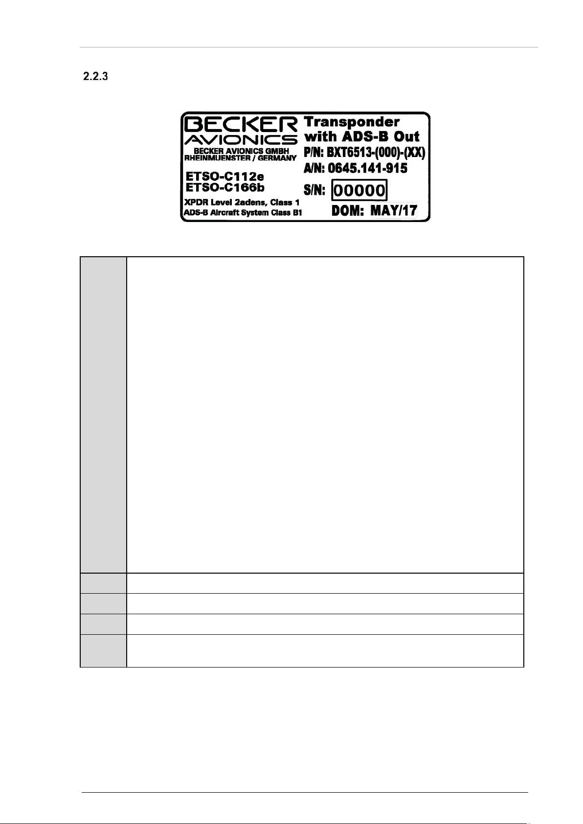
Becker Avionics
Installation
Type Plate
P/N:
Example Type designation:
S/N:
Unique number of the particular device
A/N:
Article number (=order number)
DOM:
Date of Manufacturing
Compliance and Certifications
The device type is defined by the type plate (on the housing):
Example:
Explanation:
Device Assignment
Figure 2: Type Plate (example)
BXT = Remote Controlled Transponder with ADS-B out
6513 = Mode S Transponder, basic equipment
6553 = Mode S Transponder, basic equipment+extended temperature range
Options:
-(000): Diversity
-(010): Single antenna
-(020): sCloaking (Mode S disabled)
-(XX): Modification Index e.g. BXT6513-(000)-(06)
Functionality:
XPDR class 1: Output power at antenna ≥125 W
Level 2: Surveillance and C om m -A/B
a: TCAS interface
d: Diversity
e: Extended squitter
n: Enhanced surveillance
s: Surveillance identifier code (SI)
ADS-B class
B1: Aircraft broadcast only
B1S: Aircraft broadcast only, single antenna
Corresponding to the displayed text and logos
DV15104.3 Issue 06 September 2018 BXT6500 Series 37
Page 38
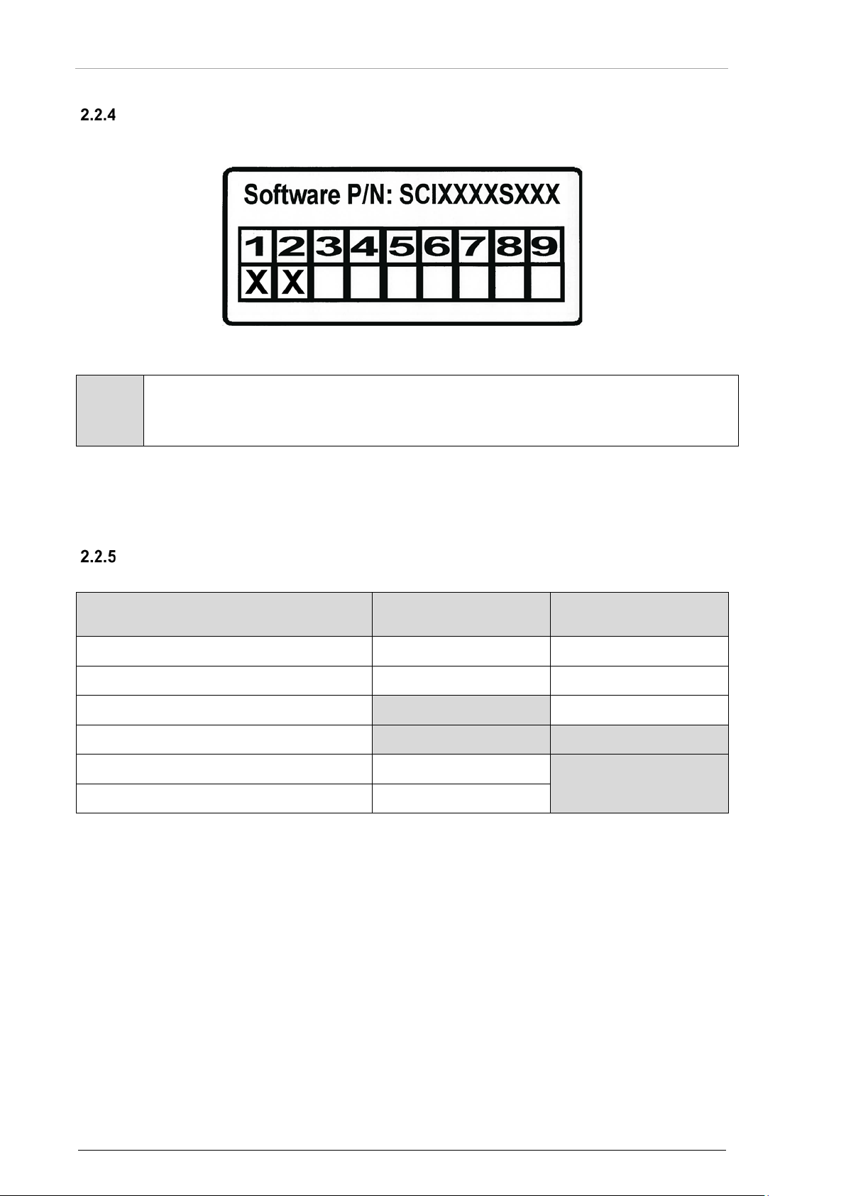
Installation
Becker Avionics
X Example description:
Device Status
ERR
(LED yellow)
OK
(LED green)
Off
off
off
Initializing
off
off
Failure of basic function(s) 1)
on
off
Failure of periphery 2)
on
on
Operating, no error
off
on
Software load mode
off
blinking
1) Typical exampl es for this failure c ase are listed i n the following:
Device Assignment
Softw are Data Plate
The software state is defined by the software data plate (on the housing):
Example:
Figure 3: Software Data Plate (example)
Explanation:
The labelling on this data plate example shows:
The software version and FPGA program version of new deliveries are subjects to change without
notice.
For detailed information about modifications you may contact our Customer Service Department.
Software status of the device = software package version 2.
Meaning of Status LEDs
The two front panel LEDs indicate basic information about overall equipment status.
antenna transmission error, receiver error, incorrect configuration source, no Mode S address, interface error of TCAS or
control port or ADLP, overtemperature alert.
2) Typical exampl es for this failure c ase are listed i n the following:
error of mutual suppression line, altimeter input error, GNSS input error or invalid position, overtemperature warning, Change
of Mode S address observed.
In case of failure:
• Check installation and see "
• Post Installation Check" page 70.
• Read out error list see "Read Out and Reset Error Flags" page 74.
• In the event of damage or a defect, the entire device must be returned for repair. The
repair must be made by trained Becker Avionics personnel.
38 BXT6500 Series DV15104.3 Issue 06 September 2018
Page 39
Becker Avionics
Installation
Mounting Requirements
The installation of the BXT65 series into an aircraft may be carried out only by an
BXT65 series design allows installation in environment of fixed and rotary wing
2.3 Mounting Requirements
The installation of the device(s) depends on the type of aircraft and its equipment and therefore only
general information can be given in this sect ion.
authorized installation company. The country regulations always have to be
observed.
Antenna and cable installations on pressurized cabin aircraft require FAA/EASA
approved installation design and engineering substantiation data whenever such
installations incorporate alteration (penetration) of the cabin pressure vessel by
connector holes and/or mounting arrangements.
Use of existing bulkhead connectors previously approved by other means is
permissible without additio nal appr ov al.
• The device must not be opened .
• When installing the device, make sure the heat dissipators of the device
receive sufficient air. Ensure air circulation gaps as specified, see "Mounting
Distance", page 40.
• The mounting place shall be at least 30 cm from the magnetic aircraft
compass, to avoid any interference to the magnetic compass.
• Make sure that the mounting plate is not exposed to external temperature
influences.
aircraft including helicopters.
Following limitations apply for the installation of the device:
• Installations must be in accordance with appropriate EASA or FAA approved
guidelines.
• The personnel installing this device must ensure that the aircraft installation
conditions are within the ETSO/TSO standards applicable for the specific type
or class of aircraft.
• The conditions and tests for ETSO/TSO approval of this article are minimum
performance standards.
• The equipment is not qualified for installation in areas where fluid
contamination is quite likely.
• Changes or modifications made to this equipment not expressly approved in
written form by Becker may void the authorization to operate this equipment.
• Protect the power supply in the application with an external fuse
(recommendation for fuse please see "Technical Data" page 24).
• Check the wiring carefully before power up the device(s) and check
particularly correct connection of the power supply lines.
DV15104.3 Issue 06 September 2018 BXT6500 Series 39
Page 40
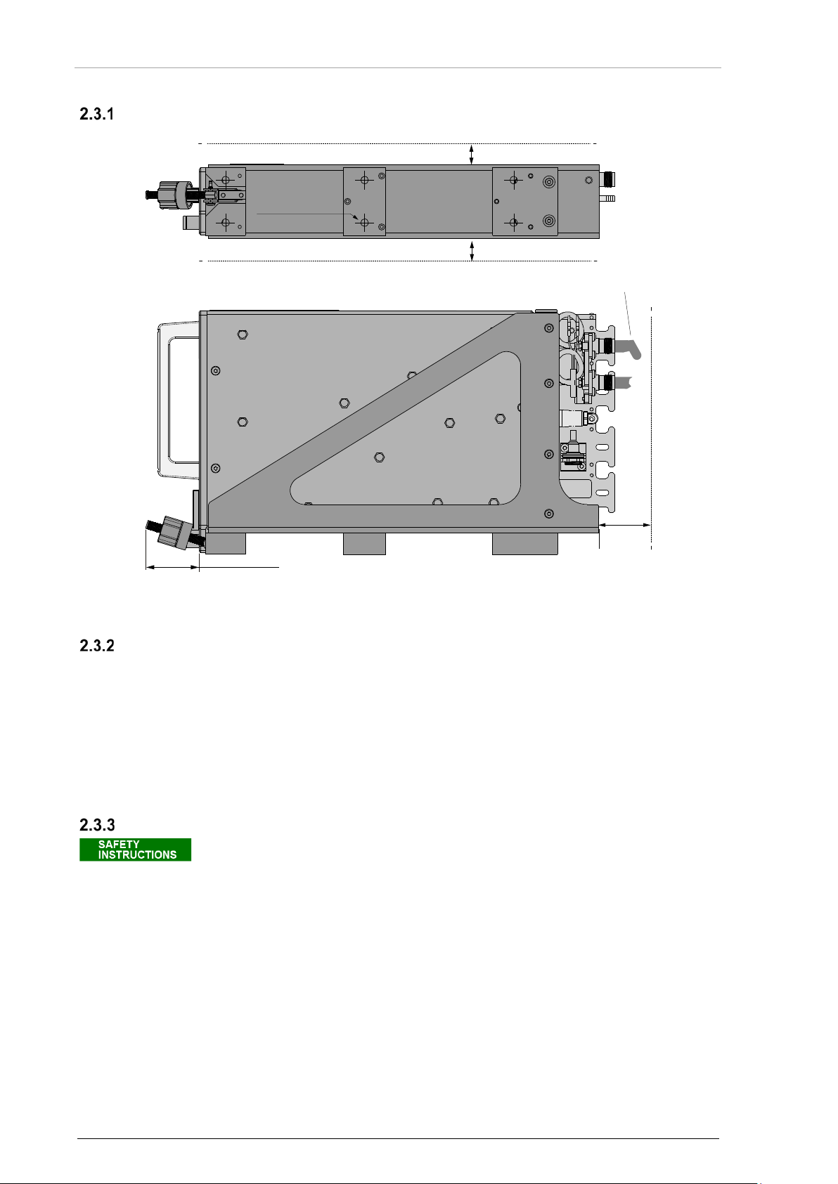
Installation
Becker Avionics
Mounting Requirements
Make sure that the grounding contact area is adequate and that the connection has
37.8 (1.48)
min 30
(1.18)
cabling area
air circulation min 15 (0.59)
air circulation min 15 (0.59)
RF cable bending radius
min R20
6x Ø5.3 (Ø0.21)
Mounting Distance
Dimensions mm (in ch)
Figure 4: BXT65 Series Mounting Area
Mounting Tray MT6533
Install the BXT65 series with the dedicated mounting parts which consists of a mounting tray
(MT6533) and a backshell (BS6533). The mounting tray provides fixing the BXT65 series to the
aircraft structure. The backshell provides fixing for cable harness. Details see "Dimensions", page 44.
• Install the mounting tray MT6533 in the aircraft avionics bay.
• Use six M5 (metric) or size 10 (imperial) screws with countersunk head.
o Minimum torque for fixing screws is 3 Nm (28 inch-lbs).
Grounding
low resistance and low inductance. Never use a grounding point on paint-coated
surfaces!
The mounting tray (MT6533) must be connected to the aircraft electrical frame:
• Use the grounding stud at the rear part of the mounting.
• Use a ground strap fixed to the ground stud on the mounting tray and to the airframe.
o Maximum tightening torque for ground stud screw is 1.5 Nm (14 inch-lbs).
o Wire cross section: min. 4 mm
o Length: max.150 mm (6 in).
2
.
40 BXT6500 Series DV15104.3 Issue 06 September 2018
Page 41
Becker Avionics
Installation
Cable Installation
Cable cross section – Crimp tool
Connector / cable cross section
Crimp tool category
(for the D-Sub connectors)
Crimps
CONEC part number: 360X10329X
Positioner
for CONEC pins – part number 360X20069X
Insertion/Removal tool
CONEC part number: 360X12009X
• General requirements (except power wires).
o Use only shielded cables.
o Connect each shield to the ground individually (no series connections).
o Connect all cable shields at both ends, ensuring large contact areas!
o Use only cables which are qualified for aircraft use (self-extinguishing).
o Interface lines TX-A/TX-B and RX-A/RX-B are each to be laid as 2-core twisted and
shielded cables.
o Fit sleeves over the solder joints on the equipment connector.
o Cable routing should be kept as short and as direct as practical.
o Avoid sharp bends to prevent cable break and defects of insulation.
o Avoid routing close to sharp edges to prevent cable break and defects of insulation
due to vibration handling the cable.
o Avoid routing cables near power sources.
o Avoid routing cables near aircraft control cables.
HF cable should not be included in the cable harnesses.
o Avoid routing antenna cables near DME, TCAS, radar altimeter, and ADF antenna
• Power supply cables.
• Shielded cables.
• Signal cables for configuration inputs.
cables (allow ≥ 12 inch separation).
o Wire cross section (cable shield – ground): AWG 24…20.
o Wire cross section (cable shield – ground): AWG 24…20.
o Shield connection length: max. 75 mm (3 in).
o Wire cross section (signal cables – ground): AWG 24…20.
o Length: max. 150 mm (6 in).
Mounting Requirements
Recommended Crimp Tools
Please always verify the use of the suited positioner (insert) in the crimping pliers
to guarantee a reliable wired connection.
DV15104.3 Issue 06 September 2018 BXT6500 Series 41
Page 42

Installation
Becker Avionics
It is recommended that "Top" & "Bottom" antenna cables have similar length.
cable type
max. loss
delay
RG400
0.5 dB/m
4.7 ns/m
RG142
0.42 dB/m
4.7 ns/m
RG393
0.29 dB/m
4.6 ns/m
ECS310801
0.11 dB/m
4.1 ns/m
ECS310701
0.10 dB/m
4.1 ns/m
Mounting Requirements
Antenna Cables
The antenna installation needs to comply with following limitations:
• The total attenuation of a connection between any antenna and the equipment, including
cables, connectors, microwave switch (if used), etc. shall not be more than 3 dB.
• The connection attenuation difference between antennas shall not be greater than 0.5 dB.
• The signal delay of a connection between any antenna and the equipment shall not be
greater than 75 ns.
• The signal delay difference between antennas shall not be greater than 20 ns.
In case of different antenna cable length for bottom and top antenna it may be
conceivable that different kinds of cable types are used.
2.3.6.1 Attenuation: Cable length vs coax cable type
Data below shall be used as guideline only.
42 BXT6500 Series DV15104.3 Issue 06 September 2018
Page 43
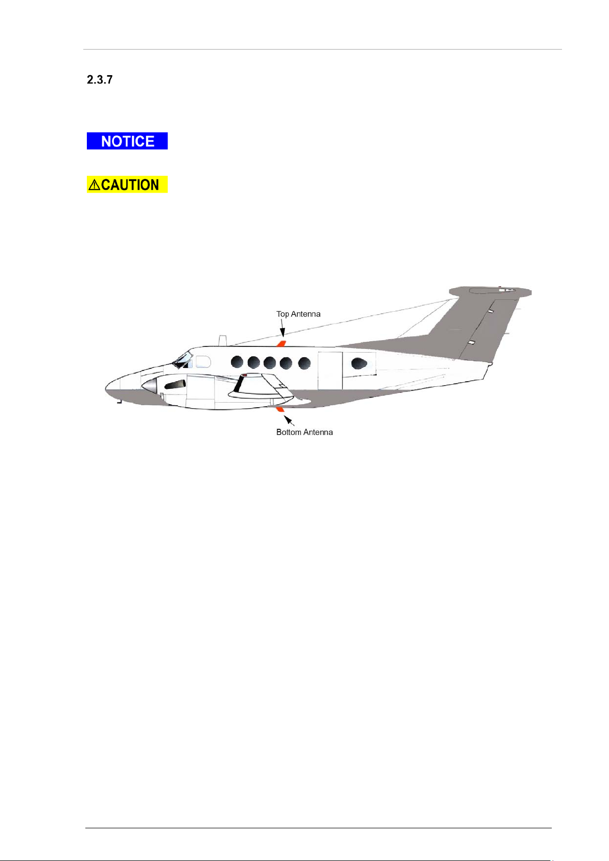
Becker Avionics
Installation
Mounting Requirements
Penetration of the pressurised cabin on a pressurised aircraft requires additional
Radiation risk:
Antenna Installation
For antenna installation, refer always to the manufacturer´s maintenance documentation for the
aircraft. Carry out the antenna installation in accordance with AC 43.12-2A Chapter 3.
data, which are not contained in this installation manual.
The picture shows a typical location for top and bottom antenna installation for Diversity Mode S
transponder. For single antenna device install only the bottom antenna.
A safe distance to the installed antenna must be ensured by corresponding
installation measures around human body damage (e.g. at the eyes) and/or avoid
the inflammation of combustible materials by radiated energy.
Figure 5: Antenna Installation (diversity)
Transponder antennas should be installed as far away as practical from:
• Other antennas.
• Shadowing produced by other installations on the surface of the aircraft body.
• Exhaust path of the engine(s).
• Landing gear doors or other openings.
• Check the skin panels for sufficient bonding before the antenna installation.
• Separate the transponder antennas from DME and TCAS as much as possible
(approx. 1.8 m or 6 feet as guideline).
• Generally, transponder antennas should not be installed closer than 3 ft to the
transponder. Otherwise RF interference may occur.
• Mount the main antenna on the bottom of the aircraft fuselage in a vertical position, same
as the top antenna. Horizontal separation of both antennas should not exceed 7.6 meters
(25 ft).
• Follow the manufacturer´s installation instruction for the antenna to ensure achieving
maximum performance of the BXT65 series.
• If existing antennas on the aircraft will be used an inspec tion of the area bet ween ante nna
and the aircraft skin is highly recommended to avoid negative effects of possible corrosion
in this area.
• On composite aircraft, add sufficient ground plane material.
DV15104.3 Issue 06 September 2018 BXT6500 Series 43
Page 44
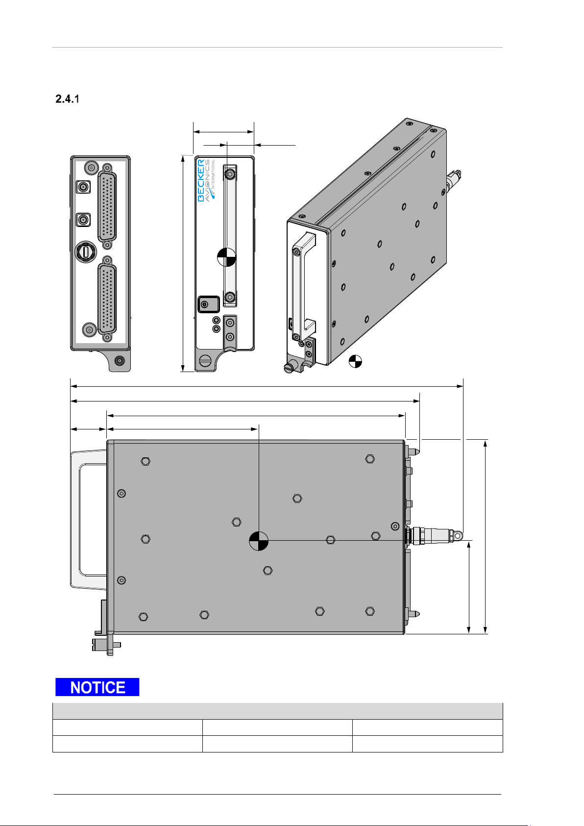
Installation
Becker Avionics
Dimensions
Allowable deviation for dimensions without tolerances: DIN ISO 2768 T1 C (dimensions in mm)
xx...6 (±0.3)
>30...120 (±0.8)
>400...1000 (±2.0)
>6...30 (±0.5)
>120...400 (±1.2)
>1000...2000 (±3.0)
USB
OK
ERR
TOPBOTEM
P2 P1
17
33
50
1
18
34
17
33
50
1
18
34
CENTER OF GRAVITY
120 (4.72)
276 (10.87)
310 (12.21)
47.4
(1.87)
22
(0.87)
74 (2.91)
154.5 (6.08)
171 (6.73)
28.8
(1.13)
235.4 (9.27)
2.4 Dimensions
Transponder BXT65 Series
Dimensions mm (in ch)
Figure 6: BXT65 Series
"Center of Gravity" for BXT65 series with EM module.
44 BXT6500 Series DV15104.3 Issue 06 September 2018
Page 45
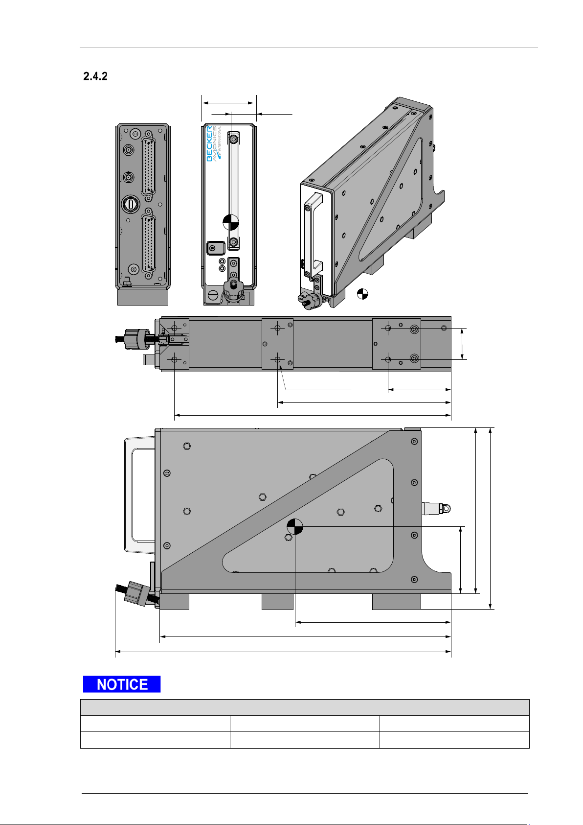
Becker Avionics
Installation
BXT65 Series with Mounting MT6533
Allowable deviation for dimensions without tolerances: DIN ISO 2768 T1 C (dimensions in mm)
xx...6 (±0.3)
>30...120 (±0.8)
>400...1000 (±2.0)
>6...30 (±0.5)
>120...400 (±1.2)
>1000...2000 (±3.0)
USB
OK ERR
CENTER OF GRA
VIT
Y
263 (10.36)
64 (2.52)
172.5 (6.79)
157.5 (6.20)
277 (10.91)
319 (12.56)
148 (5.95)
165 (6.5)
30
(1.18)
60 (2.36)6x Ø5.3 (Ø0.21)
52.4
(2.06)
24
(0.94)
Dimensions
Dimensions mm (in ch)
"Center of Gravity" for BXT65 series with EM module and mounting.
Figure 7: BXT6565 Series with Mounting Tray MT6533
DV15104.3 Issue 06 September 2018 BXT6500 Series 45
Page 46
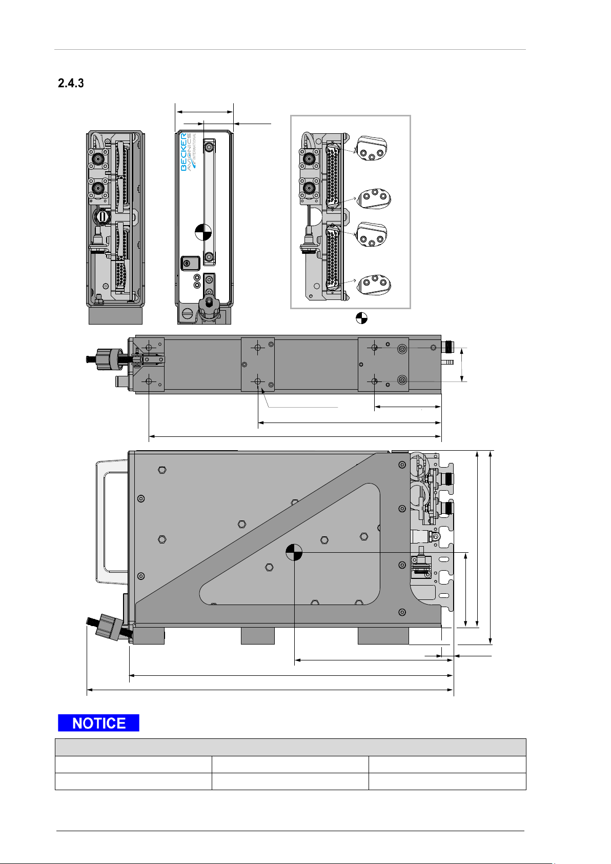
Installation
Becker Avionics
Allowable deviation for dimensions without tolerances: DIN ISO 2768 T1 C (dimensions in mm)
xx...6 (±0.3)
>30...120 (±0.8)
>400...1000 (±2.0)
>6...30 (±0.5)
>120...400 (±1.2)
>1000...2000 (±3.0)
USB
OK ERR
CENTER OF GRA
VITY
263 (10.36)
67 (2.64)
172.5 (6.79)
157.5 (6.20)
292.8 (11.53)
331 (13.03)
144 (5.67)
11.3
(0.45)
165 (6.5)
30
(1.18)
60 (2.36)6x Ø5.3 (Ø0.21)
52.4
(2.06)
27
(1.06)
Backshell without cable clamps
17
33
50
1
18
34
17
33
50
1
18
34
Dimensions
BXT65 Series with Mounting MT6533 and Backshell BS6533-(100)
Dimensions mm (in ch)
Figure 8: BXT65 Series with Mounting Tray MT6533 and Backshell BS6533-(100)
"Center of Gravity" for BXT65 series with EM module, mounting and backshell.
46 BXT6500 Series DV15104.3 Issue 06 September 2018
Page 47
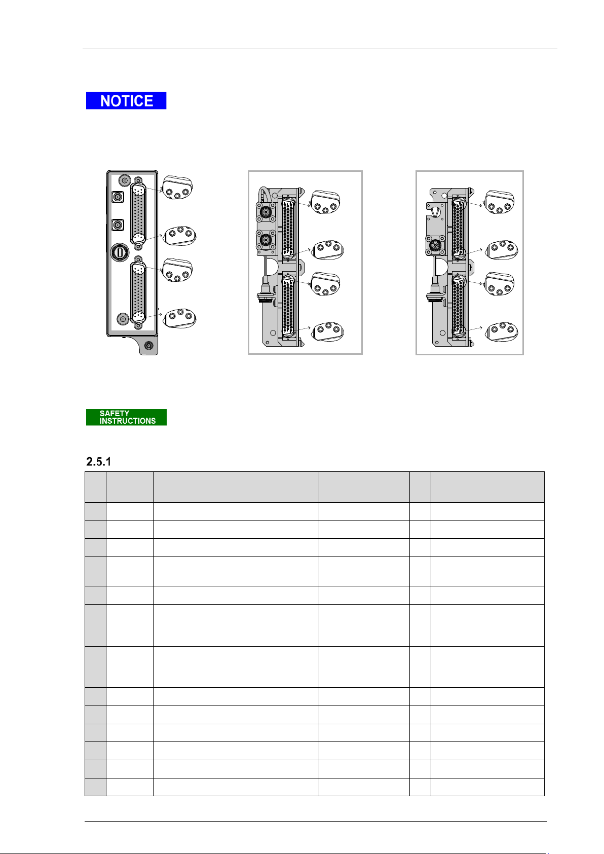
Becker Avionics
Installation
2.5 Electrical Installation
For installations in a more severe electromagnetically environment use shielded
Transponder rear side
Backshell for antenna diversity
Backshell for single antenna
Reserved pins shall not be connecte d.
P1
Signal
Pin Name
Function
I/O
Remarks
1
CAX0B
Reserved
- factory only
2
C4XXIB0
XPDR Control, Port A, Line B
ARINC 429
I
3
C4XXIB1
GNSS Data, Line B
ARINC 429/RS422
I
configurable
4
C4XXIB2
ADC/Altitude Encoder, Port A,
ARINC 429/RS422
I
configurable
5
CIX2
Reserved
- factory only
6
CIX3
XPDR Standby
Discrete
I
Low active, < 3.5 V
7
CIX0
XPDR Reply
Discrete
O
Low active, ≈ 200 ms
8
CIX1
Ident Activation
Discrete
I
Low active, < 3.5 V
9
C429IA0
FMC, Line A
ARINC 429
I 10
C429IB0
FMC, Line B
ARINC 429
I 11
C429IA1
Reserved
- factory only
12
C422IN0
Time Mark, inverting
RS422
I
Line B
13
C422IP0
Time Mark, non-inverting
RS422
I
Line A
TOPBOTEM
P2 P1
17
33
50
1
18
34
17
33
50
1
18
34
17
33
50
1
18
34
17
33
50
1
18
34
17
33
50
1
18
34
17
33
50
1
18
34
Backshell without cable clamps
17
33
50
1
18
34
17
33
50
1
18
34
Backshell without cable clamps
cable connectors and a common shielding for the transponder interwiring.
Detailed information according electrical signals and wiring; please see "Mounting
Requirements" page 39 and "Aircraft Wiring" page 66.
Electrical Installation
Figure 9: BXT65 series
Connector Layout
Connector P1
name
Pin
Line B
Figure 10: BS6533-(100)
Connector Layout
Figure 11: BS6533-(110)
Connector Layout
GND= Standby
Open=ON
DV15104.3 Issue 06 September 2018 BXT6500 Series 47
after every generated
reply.
Page 48

Installation
Becker Avionics
Electrical Installation
P1
Signal
Pin Name
Function
I/O
Remarks
14
CSI1
Configuration Source Select
Discrete
I
data source
15
CRDY
System Status
Discrete
O
High active, > 15.0 V
16
PGND
Ground
Supply Return
- 17
PGND
Ground
Supply Return
- 18
CAX0A
Reserved
- factory only
19
C4XXIA0
XPDR Control, Port A, Line A
ARINC 429
I 20
C4XXIA1
GNSS Data, Line A
ARINC 429/RS422
I
configurable
21
C4XXIA2
ADC/Altitude Encoder, Port A,
ARINC 429/RS422
I
configurable
22
C429XB0
XPDR Data, Port A, Line B
ARINC 429
O
23
C429XA0
XPDR Data, Port A, Line A
ARINC 429
O 24
GND
Ground
Signal Return
-
25
C429XB1
Reserved
- factory only
26
C429XA1
Reserved
- factory only
27
C429XB2
Reserved
- factory only
28
C429XA2
Reserved
- factory only
29
GND
Ground
Signal Return
-
30
CSI0
Configuration Source Selection
Discrete
I
data source
31
CSI2
XPDR Source/Destination select
Discrete
I
device number (No.1,
32
SUPP
DC Power Supply
28 VDC aircraft
I 33
SUPP
DC Power Supply
28 VDC aircraft
I
34
C3V3
External Memory Module supply
Supply
I
35
CSDA
External Memory Module data
Data
I/O 36
CSCL
External Memory Module clock
Clock
O
37
GND
Ground
Signal Return
-
38
CCANN0
CAN Bus, Port 0, Low
CAN
I/O 39
CCANP0
CAN Bus, Port 0, High
CAN
I/O
40
C4XXIA3
ADC/Altitude Encoder, Port B,
ARINC 429/RS422
I
configurable
41
C4XXIB3
ADC/Altitude Encoder, Port B,
ARINC 429/RS422
I
configurable
42
GND
Ground
Signal Return
- 43
CSIX
Mutual Suppression
ARINC 718A
I/O
44
CIHL0
Weight on Wheel Sensor
Discrete
I
active State
name
Pin
configuration
Line A
Line A
Line B
configuration
No.2) in dual
installations
power
power
48 BXT6500 Series DV15104.3 Issue 06 September 2018
configurable, (High or
Low active)
Page 49

Becker Avionics
Installation
P1
Signal
name
Pin Name
Function
I/O
Remarks
45
C429IB1
Reserved
- factory only
46
GND
Ground
Signal Return
-
47
CSI3
Transmitter Test Inhibit
Discrete
I
active if strapped to
48
CI10
ADC/Altitude Encoder Port Sel ec t
Discrete
I
Source selection
49
CI11
Reserved
- factory only
50
CILLI
Reserved
- factory only
P2
Signal
Pin Name
Function
I/O
Remarks
1
CAX1B
Reserved
- factory only
2
CI9
Reserved
- factory only
3
CIX7
Reserved
- factory only
4
CIX6
ADS-B Function Status
Discrete
I/O
Closed = ADS-B
5
CIX4
Reserved
- factory only
6
CIX5
Burst mode enable
Discrete
I
Low = Enabled
7
C429XB7
XPDR Data, Port B, Line B
ARINC 429
O
8
C429XA7
XPDR Data, Port B, Line A
ARINC 429
O 9
C429XB6
TCAS Interface, Line B
ARINC 429
O
Output to TCAS
10
C429XA6
TCAS Interface, Line A
ARINC 429
O
Output to TCAS
11
C429XB5
ADLP Output, Line B
ARINC 429
O 12
C429XA5
ADLP Output, Line A
ARINC 429
O
13
C232X
Reserved
- factory only
14
C429XB4
Reserved
- factory only
15
C429XA4
Reserved
- factory only
16
C429XB3
Reserved
- factory only
17
C429XA3
Reserved
- factory only
18
C4XXIA4
XPDR Control, Port B, Line A
ARINC 429
I 19
C4XXIB4
XPDR Control, Port B, Line B
ARINC 429
I 20
C4XXIB5
XPDR Control, Port C, Line B
ARINC 429
I 21
C4XXIB6
Reserved
- factory only
22
CI8
XPDR Control Port Select
I
23
C4XXIB7
Reserved
- factory only
Pin
Connector P2
name
Pin
Electrical Installation
GND.
Low = Port B
High= Port A
position data receiving,
(max. drain = 100 mA)
Open = No valid
position data available
High = Disabled
DV15104.3 Issue 06 September 2018 BXT6500 Series 49
Page 50

Installation
Becker Avionics
Electrical Installation
P2
Signal
Pin Name
Function
I/O
Remarks
24
GND
Ground
Signal Return
-
25
CLRXN
Ethernet Receive
10/100BASE-TX
I/O
26
CLTXN
Ethernet Transmit
10/100BASE-TX
I/O
27
C429IA7
Data Concentrator, Port A,
ARINC 429
I/O 28
C429IA6
Radio Altimeter/Data
ARINC 429
I/O
configurable
29
GND
Ground
Signal Return
-
30
C429IA5
IRS, Port A
ARINC 429
I 31
C429IA4
TCAS Data, Port A
ARINC 429
I
Input from TCAS
32
C429IA3
FCC/MCP Data, Port A
ARINC 429
I
33
C429IA2
ADLP, Port A
ARINC 429
I
Data from ADLP
34
CAX1A
Reserved
- factory only
35
GND
Ground
Signal Return
-
36
C4XXIA5
XPDR Control, Port C, Line A
ARINC 429
I 37
C4XXIA6
Reserved
- factory only
38
CIX13
Extended Squitter Disable
Discrete
I
Low = Disabled
39
C4XXIA7
Reserved
- factory only
40
CIX14
Software Update Enable
Discrete
I
High = Normal operation
41
CLRXP
Ethernet Receive
10/100BASE-TX
I 42
GND
Ground
Signal Return
- 43
CLTXP
Ethernet Transmit
10/100BASE-TX
O
44
C429IB7
Data Concentrator, Port A,
ARINC 429
I/O 45
C429IB6
Radio Altimeter/Data
ARINC 429
I/O
configurable
46
GND
Ground
Signal Return
- 47
C429IB5
IRS, Port B
ARINC 429
I 48
C429IB4
TCAS Data, Port B
ARINC 429
-
Input from TCAS
49
C429IB3
FCC/MCP Data, Port A
ARINC 429
I
Data from FCC/MCP
50
C429IB2
ADLP, Port B
ARINC 429
I
Data from ADLP
name
Pin
Line A
Concentrator, Port B, Line A
High = Enabled
Low = Update enabled
Line B
Concentrator, Port B, Line B
Connector TOP, BOT (Antenna)
• Type: BMA female at the rear side of the device (transformed into TNC by the backshell
BS6533).
• Antenna cable: low-loss cable.
• Signal: bi-directional.
50 BXT6500 Series DV15104.3 Issue 06 September 2018
Page 51
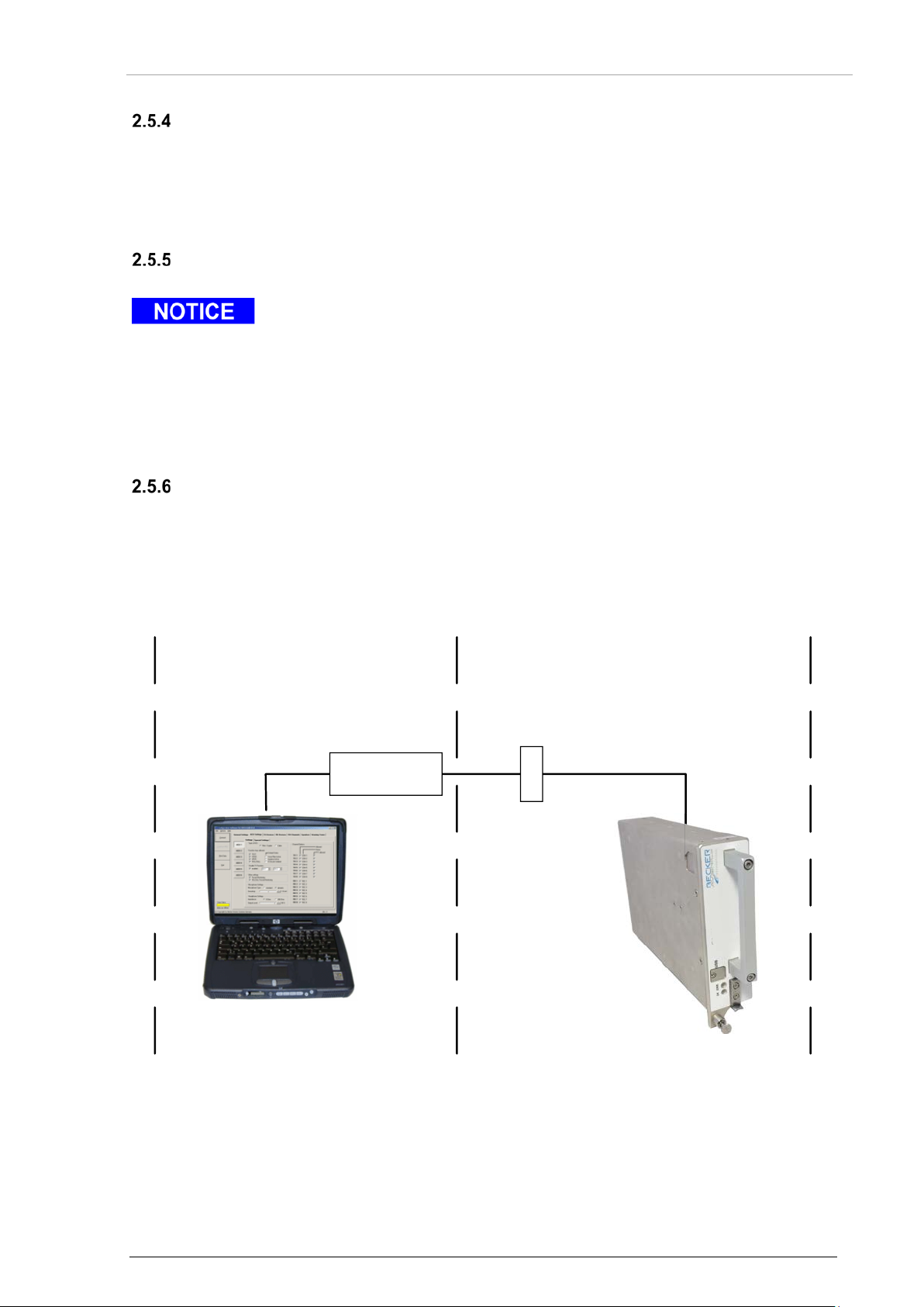
Becker Avionics
Installation
Electrical Installation
Software + Adapter
CAN-BusAdapter
(USB)
CANbus Kit Installation
Service Connector
CAN-Bus
Connector USB
• Only for service operation.
• Type: USB 2.0 Micro B.
• Cable: Max. cable length: 5 m (15 ft).
• Data transfer: Bidirectional data exchange.
Connector EM
Connection for external memory, if installed.
• Please mount a dust cup on EM connector (BXT rear side) if this connector is
not used.
For example:
• Internal memory is used.
• External memory module EM6100 connection is done via backshell.
Service Connector (optional)
Becker Avionics recom mend the installation of a service connector. This allows the configuration of
the BXT65 series and software updates after installation inside the aircraft.
2.5.6.1 Service connector inside the aircraft
Pinout service connector (Dsub, 9pol.) see "Figure 13: Wiring Diagram (diversity example, external
memory)" page 55.
DV15104.3 Issue 06 September 2018 BXT6500 Series 51
Figure 12: Service Connector inside the Aircraft
Page 52

Installation
Becker Avionics
Interfaces
Parameter
Label
XPDR control
016 or 031
Selected altitude
102
GNSS track angle
103
GNSS latitude
110
GNSS longitude
111
GNSS ground speed
112
GNSS latitude fine
120
GNSS longitude fine
121
GNSS horizontal integrity limit
130
GNSS vertical figure of merit
136
UTC fine
140
UTC
150
Radio altitude
164
GNSS vertical velocity
165
North-south velocity
166
East-west veloc ity
174
Altitude
203
Mach number
205
Indicated airspeed
206
True airspeed
210
Altitude rate
212
Flight ID
233…237 or 360
Baro correction
234
GNSS horizontal figure of merit
247
Ground speed
312
True track angle
313
True heading
314
Magnetic heading
320
Roll angle
325
Track angle rate
335
Inertial vertical velocity
365
GNSS altitude, HAE
370
2.6 Interfaces
ARINC 429 Input Labels
52 BXT6500 Series DV15104.3 Issue 06 September 2018
Page 53

Becker Avionics
Installation
ARINC 429 Out put Labels
Parameter
Label
TCAS Display Control
013
Display Altitude Limits
015
Display Altitude Limits
016
Transponder Status
031
Event-Driven Message Status
155
Altitude
203
Baro Corrected Altitude
204
Flight ID, Part 1
233
Flight ID, Part 2
234
Flight ID, Part 3
235
Flight ID, Part 4
236
Flight ID, Part 5
237
Mode S Address, Part 1
275
Mode S Address, Part 2
276
Maintenance Data 0
350
Maintenance Data 3
353
Maintenance Data 4
354
GA Equipment Identification
371
Equipment Identification
377
Interfaces
DV15104.3 Issue 06 September 2018 BXT6500 Series 53
Page 54

Installation
Becker Avionics
Configuration
Set to
Air Data Source Configuration
Single
Air Data Format and Resolution
ARINC 429
Air Data Port A Selection
Dedicated port
Ground Sensor Enable
Enable, active low
XPDR Control Port A Selection
Dedicated port
TCAS Interface Enable
Disable
ADLP Interface Enable
Enable
FMC Input Selection
Dedicated port
GNSS Receiver Input Selection
Dedicated port
GNSS Data Format
ARINC 743A
The figures of the wiring examples are designe d with a BXT6513-(XXX) but the
Configuration
2.7 Configuration
The figure "General Architecture (example)", page 55 shows an example of a single device installation
including:
• Power supply without separate switch.
• Configuration from internal memory.
• Single ADC conformant to ARINC 706.
• FMC.
• ADLP.
• GNSS sensor conformant to ARINC 743A.
• Weight-on-wheels switch, active low.
• Indicators for system status and transponder reply.
• Standby switch.
• Dual antenna (Diversity).
Relevant configuration settings:
• Service Connector (optional).
examples are applicable to all variants of BXT65XX corresponding to the
extension level.
If an example refers to only one product variant or preclude variants it will be
pointed out.
54 BXT6500 Series DV15104.3 Issue 06 September 2018
Page 55
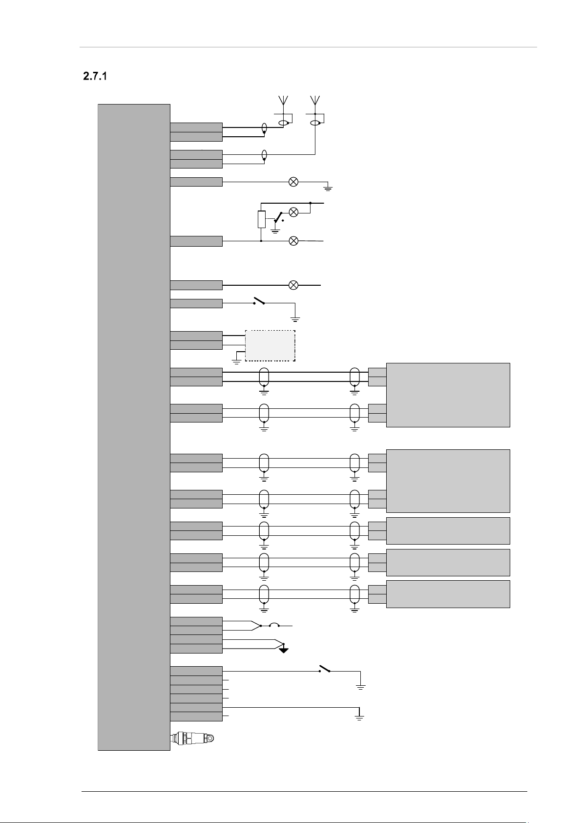
Becker Avionics
Installation
General Architecture (example)
OUT-A
OUT-B
TMARK-P
TMARK-N
OUT-A
OUT-B
OUT-A
OUT-B
OUT-A
OUT-B
OUT-A
OUT-B
IN-A
IN-B
TOP-IN
GND
BOT-IN
GND
C4XXIA1
C4XXIB1
C422IP0
C422IP1
C429IA2
C429IB2
C429IA0
C429IB0
C4XXIA2
C4XXIB2
C4XXIA0
C4XXIB0
SUPP
SUPP
PGND
PGND
CIX3
CIX5
CSI3
CSI2
CSI1
CSI0
C429XA5
C429XB5
CRDY
CIX0
CIX6
CIHLO
TOP-IN
TOP-OUT
BOT-IN
BOT-OUT
P1-20
P1-3
P1-13
P1-12
P2-33
P2-50
P1-9
P1-10
P1-21
P1-4
P1-19
P1-2
P1-32
P1-33
P1-16
P1-17
P1-6
P2-6
P1-47
P1-31
P1-14
P1-30
P2-12
P2-11
P1-15
P2-4
P1-7
P1-44
OK
REPL
Y
ADS-B
Function status
+28 VDC
+28 VDC
ADS-B Fail
WoW switch, (closed on ground)
Operating
Standby
Do not connect
Do not connect
Do not connect
Do not connect
3 A
+28 VDC
+28 VDC Power
Supply Ground
Top Antenna BottomAntenna
GNSS Sensor
ADLP
Flight Management
Computer
ADC
Control Panel
BXT6513-(XXX)
CCANP0
CCANN0
P1-39
P1-38
Service Connector (optional)
Dsub,
9pol,
female
2
3
7
External Memory
EM
Configuration
DV15104.3 Issue 06 September 2018 BXT6500 Series 55
Figure 13: Wiring Diagram (diversity example, external memor y )
Page 56
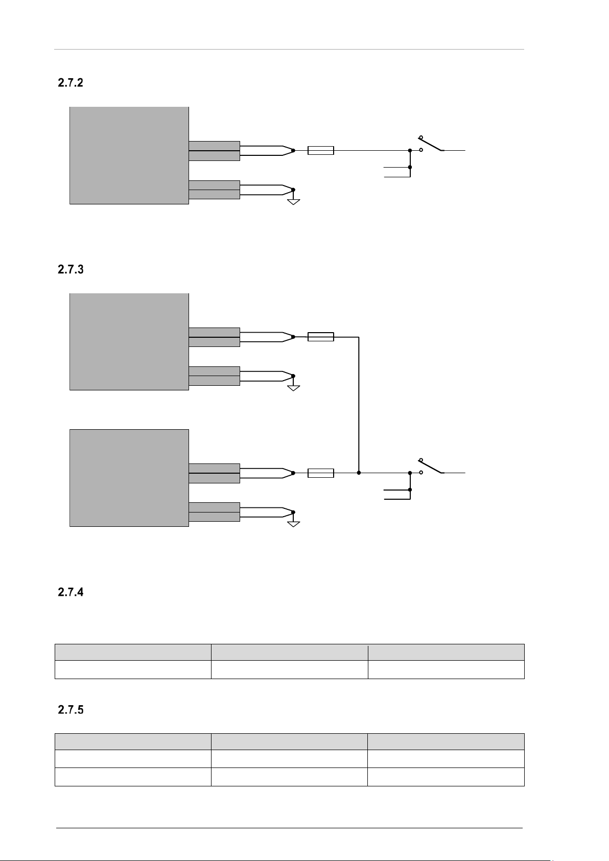
Installation
Becker Avionics
Configuration
Device installation number
device 1
device 2
P1 pin31
do not connect
GND
Data source
Internal memory
External memory
P1 pin14
do not connect
GND
P1 pin30
GND
do not connect
SUPP
SUPP
PGND
PGND
P1-32
P1-33
P1-16
P1-17
Avionic Master Switch
+28 VDC
Supply Ground
other
equipment
3 A
BXT6513-(XXX)
SUPP
SUPP
PGND
PGND
P1-32
P1-33
P1-16
P1-17
Avionic Master Switch
+28 VDC
Supply Ground
other
equipment
3 A
BXT6513-(XXX)
2
SUPP
SUPP
PGND
PGND
P1-32
P1-33
P1-16
P1-17
Supply Ground
3 A
BXT6513-(XXX) 1
Single Device Installation
Electrical connections:
Dual Device Installation
Electrical connections:
Figure 14: Single Device Installation
Device Install ation Number
• In a single device installation set the installation number to 1.
Select the data source:
56 BXT6500 Series DV15104.3 Issue 06 September 2018
• In a dual device installation set the installation number for one device to 1 and for the
other device to 2.
Data Source Configuration
Figure 15: Dual Device Installation
Page 57
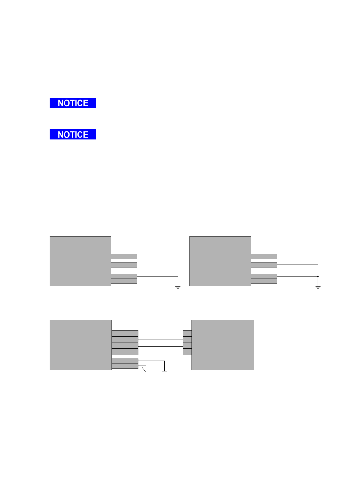
Becker Avionics
Installation
Configuration
Do not install two External Memory modules at same device. The External
In dual device installations w ith Ex tern al Memory module as a configuration data
CSI3
CSI2
CSI1
CSI0
P1-47
P1-31
P1-14
P1-30
Do not connect
Do not connect
Do not connect
BXT6513-(XXX) 1
CSI3
CSI2
CSI1
CSI0
P1-47
P1-31
P1-14
P1-30
Do not connect
Do not connect
BXT6513-(XXX) 2
C3V3
CSCL
CSDA
GND
P1-35
P1-37
P1-34
P1-36
CSDA
GND
C3V3
CSCL
green
black
red
yellow
BXT6513-(XXX) EM FIX CPL
(with EM6100)
CSI1
CSI0
P1-14
P1-30
Do not connect
2.7.5.1 External Memory Module
External memory interface s igna ls are avai lab le at P1 connector and EM connector.
If the External Memory module EM6100 is used as configuration data source the mechanical
installation is as per description:
• Backshell installation
(fix the EM6100 module to the pre-assembled connector at the backshell. Please note,
Electrical connections:
use a cable connection as short as practical but not longer than 150 mm).
Memory module must always be installed when it is defined as configuration data
source (see "
Data Source Configura tio n", page 56.
source, each device needs its own External Memory module.
In case of dual device installation, it is the responsibility of the installer to provide
correlated data to each device.
Please make sure that configuration data of both devices match to the aircraft and
installation. Aircraft properties include:
• Mode S address.
• Maximum airspeed.
• Aircraft registration.
• Aircraft category.
• Length and width code.
Figure 16: Dual Device Installation, Data Source = External Memory Module
Figure 17: External Memory Module via Backshell
DV15104.3 Issue 06 September 2018 BXT6500 Series 57
Page 58
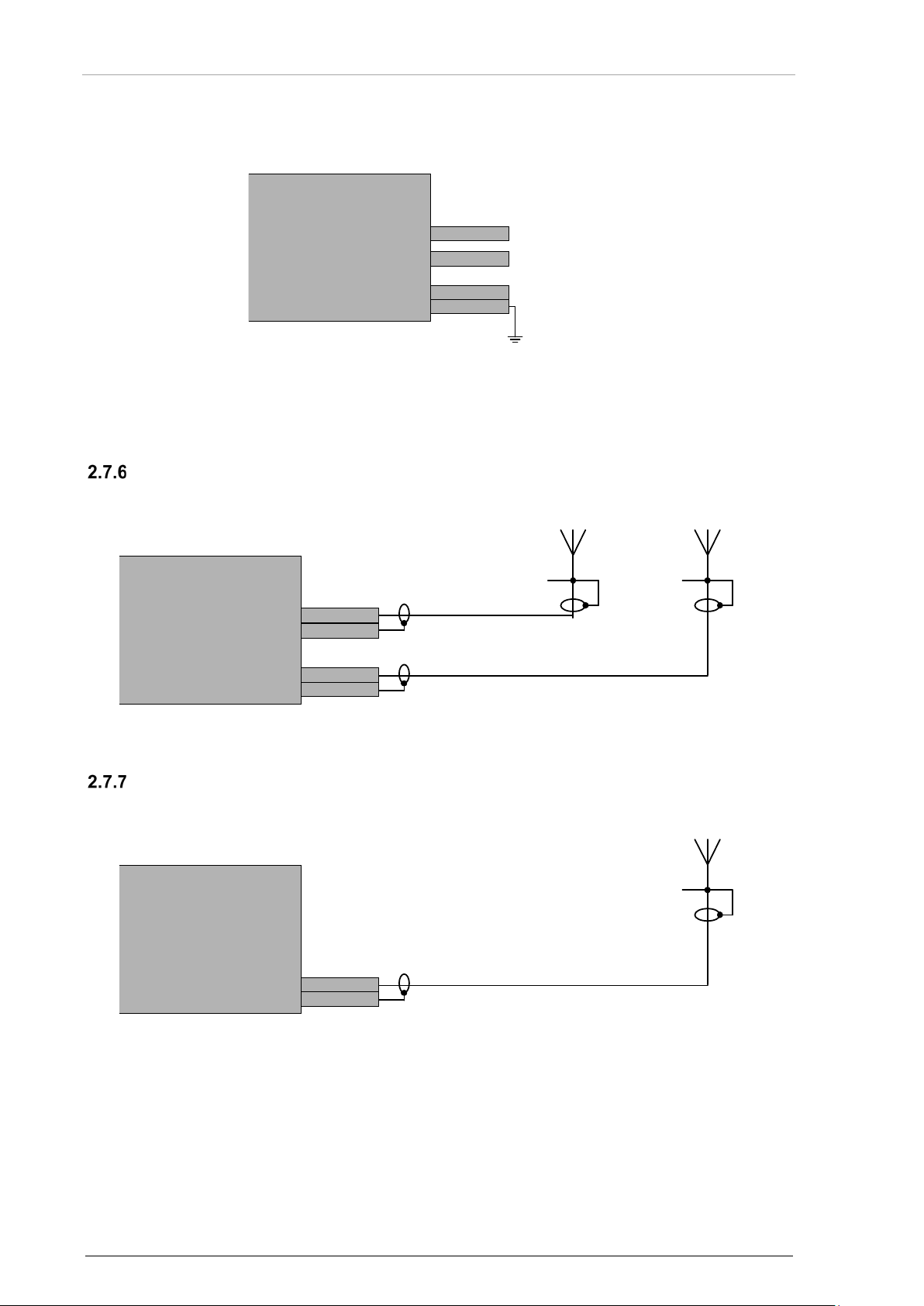
Installation
Becker Avionics
Configuration
CSI3
CSI2
CSI1
CSI0
P1-47
P1-31
P1-14
P1-30
Do not connect
Do not connect
Do not connect
Signal ground
BXT6513-(XXX)
TOP
GND
BOT
GND
TOP
GND
BOT
GND
Top Antenna BottomAntenna
BXT6513-(XXX)
BOT
GND
BOT
GND
BottomAntenna
BXT6513-(XXX)
2.7.5.2 Internal Memory
Electrical connections:
Figure 18: Single Device Installation, Data Source = Internal Memory
Single Device Installation - Antenna Diversity
Electrical connections:
Electrical connections:
Figure 19: Single Device Installation - Antenna Diversity
Single Device Installation – Single Antenna
Figure 20: Single Device Installation – Single Antenna
58 BXT6500 Series DV15104.3 Issue 06 September 2018
Page 59
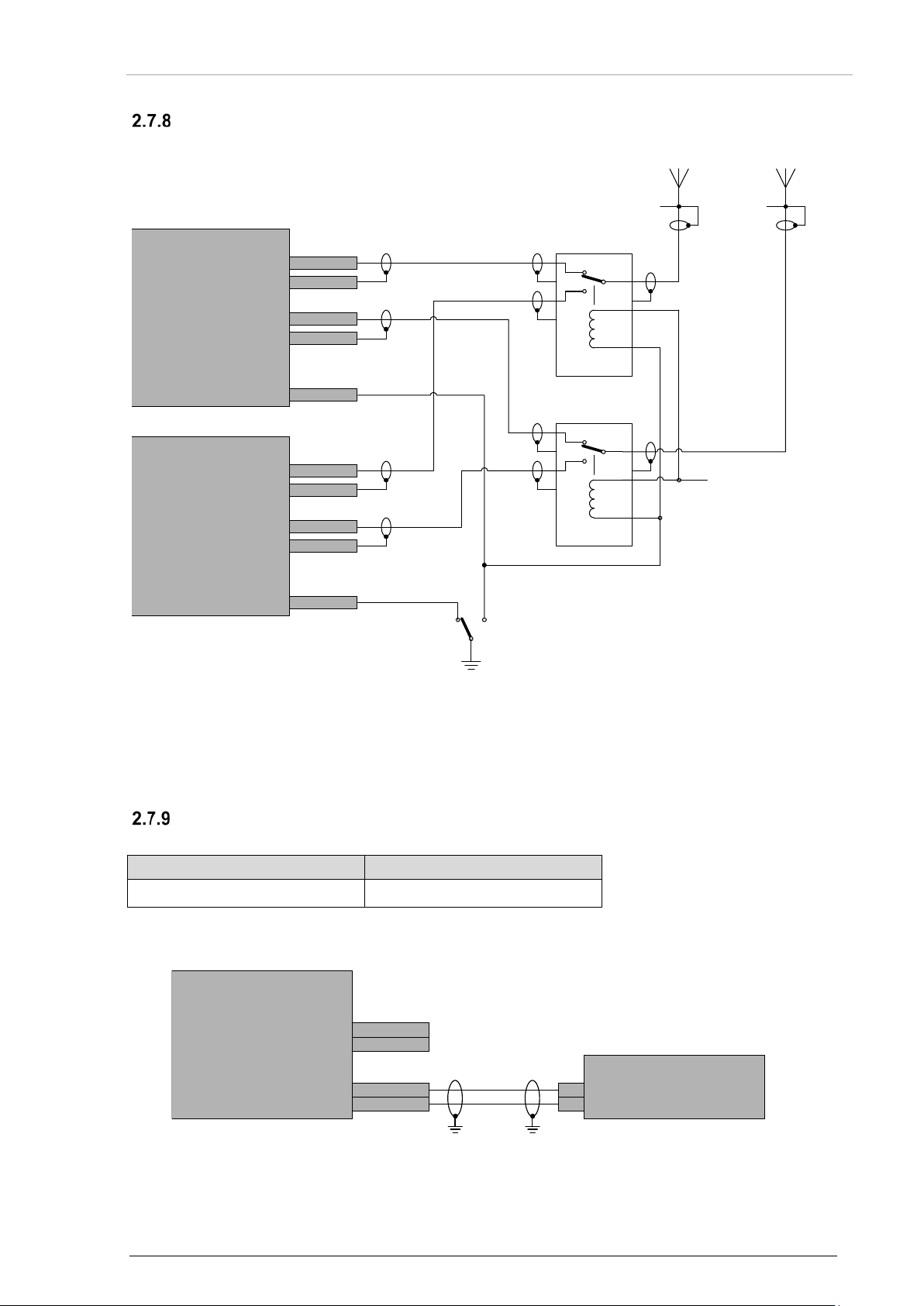
Becker Avionics
Installation
Dual Device Installation - Antenna Diversity
Option
Set to
XPDR Control Port A Selection
Dedicated Port
TOP
GND
BOT
GND
TOP-IN
TOP-OUT
BOT-IN
BOT-OUT
CIX3 P1-6
TopAntenna
Microwave switch
Microwave switch
Unit 1 ON Unit 2 ON
BottomAntenna
+28 VDC
BXT6513-(XXX) 1
TOP
GND
BOT
GND
TOP-IN
TOP-OUT
BOT-IN
BOT-OUT
CIX3 P1-6
BXT6513-(XXX) 2
CI8
CIX5
C4XXIA0
C4XXIB0
P1-19
P1-2
P1-22
P2-6
OUT-A
OUT-B
BXT6513-(XXX)
Controller
Do not connect
Do not connect
Electrical connections:
Configuration
Note: Example for antenna switch model: D2-729B003.
Single Device Installation – Single Controller
Relevant configuration settings:
Electrical connections:
DV15104.3 Issue 06 September 2018 BXT6500 Series 59
Figure 21: Dual Device Installation - Antenna Diversity
Figure 22: Single Device Installation - Single Controller
Page 60
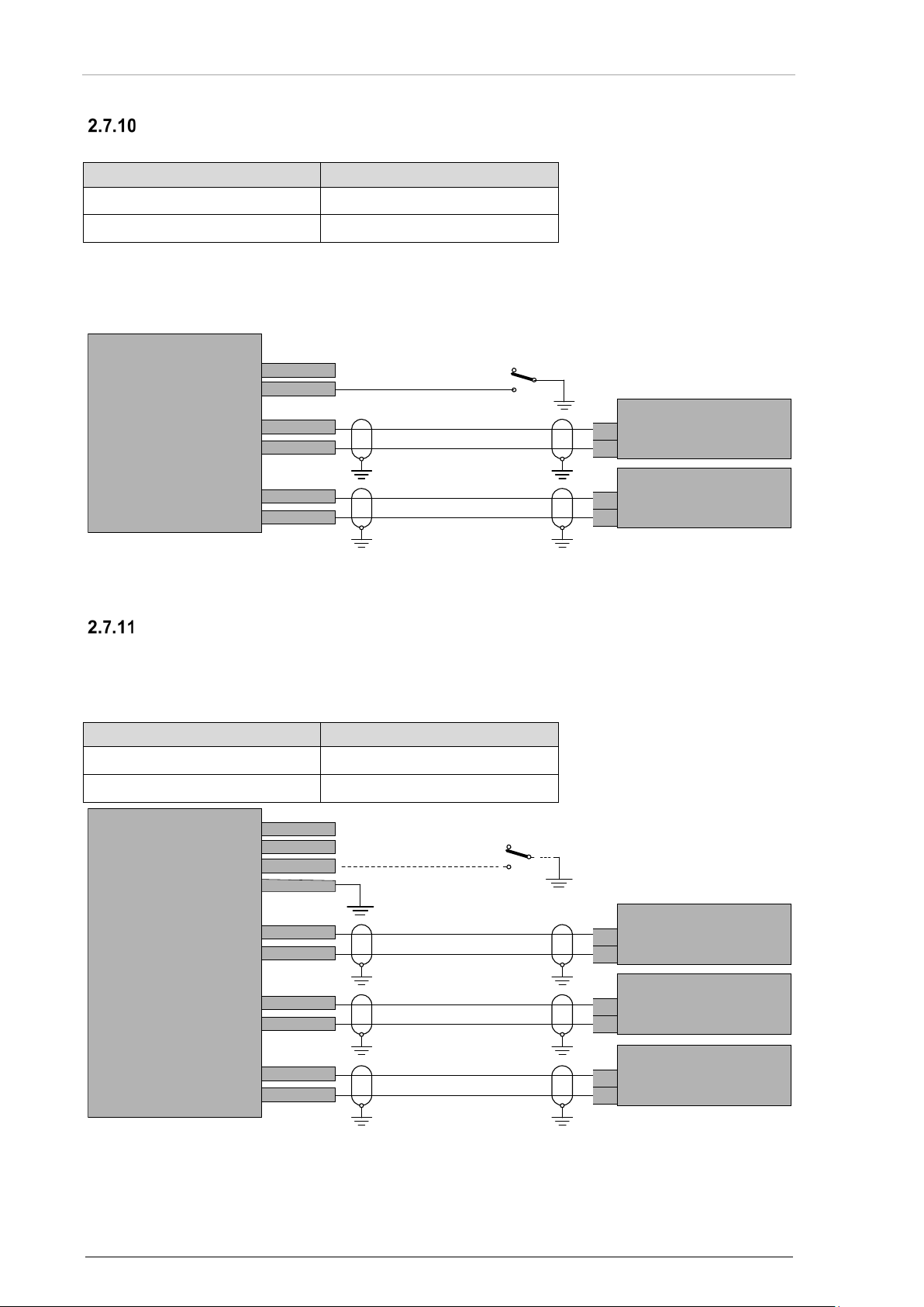
Installation
Becker Avionics
Option
Set to
XPDR Control Port A Selection
Dedicated Port
XPDR Control Port B Selection
Dedicated Port
Option
Set to
XPDR Control Port A Selection
Dedicated Port
XPDR Control Port B Selection
Dedicated Port
CIX5
CI8
P2-6
P2-22
C4XXIA0
C4XXIB0
P1-19
P1-2
C4XXIA4
C4XXIB4
P2-18
P2-19
BXT6513-(XXX)
Do not connect
Controller 1
Controller 2
OUT-A
OUT-B
Controller1
Controller2
OUT-A
OUT-B
CIX5
CIX3
CI8
CSI2
P2-6
P1-6
P2-22
P1-31
C4XXIA0
C4XXIB0
P1-19
P1-2
C4XXIA4
C4XXIB4
P2-18
P2-19
BXT6513-(XXX)
OUT-A
OUT-B
Controller1
Controller2
OUT-A
OUT-B
C4XXIA5
C4XXIB5
P2-36
P2-20
other Controller
OUT-A
OUT-B
Do not connect
Do not connect
On
Standby
Configuration
Single Device Installation – Dual Controller (Selection by Switch)
Relevant configuration settings:
Electrical connections:
With open switch, Controller 1 controls the transponder function.
With closed switch, Controller 2 controls the transponder function.
Figure 23: Single Device Installation – Dual Controller
Single Device Installation – Dual Controller (Burst Mode)
The burst mode allows for up to three sources to control the transponder operation. The selection of
the active source is dynamic. The operation in burst mode depends on "XPDR Burst Mode Contro l "
option.
Relevant configuration settings:
60 BXT6500 Series DV15104.3 Issue 06 September 2018
Figure 24: Single Device Installation – Dual Controller (Burst Mode)
Page 61
Becker Avionics
Installation
Configuration
Option
Set to
XPDR Burst Mode Control
Sticky
Option
Set to
XPDR Burst Mode Control
Concentrator
Operation
Remarks
P1 pin47
enable
do not connect
Normal configuration
P1 pin47
disabled
GND
No transmissions from equipment – for
2.7.11.1 Burst Mode - Sticky Mode Operation
The device scans all control inputs for presence of control words. Once a command word is received
from an input, th e device "s ticks" to this input - accepts command f rom this input and ignores other
inputs for as long as the selected input provides commands periodically. Once commands stop to
arrive, the device restarts the input scanning process.
Relevant configuration settings:
2.7.11.2 Burst Mode - Concentrator Mode Operation
The device processes commands from each controller with a "last command wins" principle. This
mode should typically be used with controllers operating in bursts, with "XPDR Operation on
Command Loss" set to "Continue".
Relevant configuration settings:
Transmitter Disable
This input is relevant for several tests during shop maintenance.
Leave this input open in all installations.
Relevant configuration settings:
tests only
DV15104.3 Issue 06 September 2018 BXT6500 Series 61
Page 62
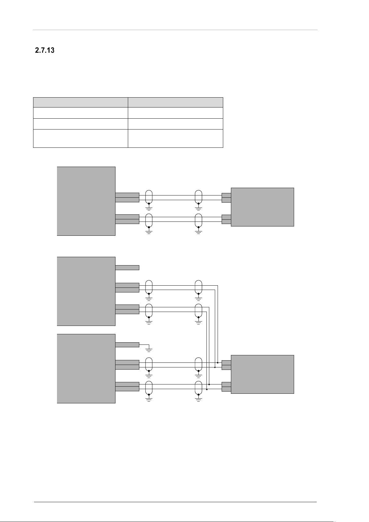
Installation
Becker Avionics
Option
Set to
GNSS Receiver Enable
Enabled
GNSS Receiver Input Selection
Dedicated Port
GNSS Data Format
ARINC 743 or
BXT6513-(XXX)
OUT-A
OUT-B
TMARK-P
TMARK-N
GNSS Sensor
C4XXIA1
C4XXIB1
C422IP0
C422IP1
P1-20
P1-3
P1-13
P1-12
BXT6513-(XXX) 2
OUT-A
OUT
-B
TMARK-P
TMARK-N
GNSS Sensor
C4XXIA1
C4XXIB1
C422IP0
C422IP1
P1-20
CSI2 P1-31
P1-3
P1-13
P1-12
BXT6513-(XXX) 1
C4XXIA1
C4XXIB1
C422IP0
C422IP1
P1-20
CSI2 P1-31
P1-3
P1-13
P1-12
Do not connect
GNSS Wiring
• BXT65XX supports ARINC429/ARINC743 GNSS sensors and RS232 GNSS sensors with
Freeflight protocol (RS232 GNSS sensors are supported with BXT6513 software version 5
or higher, BXT6553 software version 1 or higher).
o GNSS data format (protocol) is selectab le via configuration.
Relevant configuration settings:
Electrical connections:
FreeFlight Systems
Figure 25: Single Device Installation - GNSS Wiring
62 BXT6500 Series DV15104.3 Issue 06 September 2018
Figure 26: Dual Device Installation - GNSS Wiring
Page 63

Becker Avionics
Installation
Configuration Data
2.8 Configuration Data
The BXT65 series must be configured with the characteristic aircraft data.
The BXT65 series configuration is stored in a non-volatile memory.
There are two possibilit ies where to store or load configurat ion data (see "D ata Source Conf iguration "
page 56):
• Usage of the internal memory or
• Usage of an external memory module.
The configuration parameters of the BXT65XX with EM module can be set directly by PC via
"EMP Kit" and the corresponding software program.
Detailed information is available in "EMP Extended Memory Programmer User Manual", please see "Order Code", "Available
Documentation" page 32.
• We recommend the usage of the External Memory module EM6100 as data
source.
Configur ation of BXT65XX with EM module
Configur ation of BXT65XX with internal memory
• The usage of the internal memory as configuration data storage can only be
approved when customers have and maintain an own configuration data base.
o It is a condition to store the current configuration data in the
configuration data base.
• If the internal memory is used it is necessary to install a service connector at a
suitable place inside the aircraft to be able to configure the device without
For detailed information please contact Becker Avionics.
For relevant department and addresses, please see contact info page 2.
For wiring example - service connection - see also "Figure 27: Software Update – Aircraft Installation" page 64.
removing it.
DV15104.3 Issue 06 September 2018 BXT6500 Series 63
Page 64
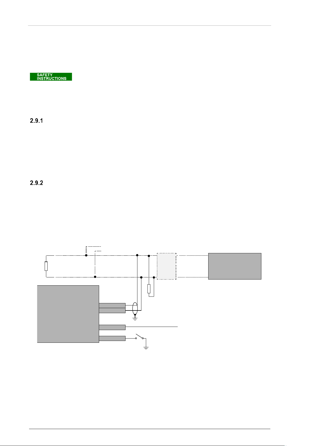
Installation
Becker Avionics
CCANP0
CCANN0
CIX14 P2-40
Update Control
closed=enable
P1-39
P1-38
CAN-H
120 Ω
120 Ω
other CAN device
CAN-L
BXT6513-(XXX)
CAN-bus adapter
CIHL0 P1-44
*
Service Connector
(optional)
Dsub,
9pol,
female
2
7
Software Update
2.9 Software Update
The BXT65 series prov ides an interfac e for Field Loadabl e Software (FLS). This i nterface enables infield loading of equipment software and device configuration.
Details see "FLS Manual" (Field Loadable Software) included in acces sories FLS6500-BXT Kit; see "Order Code" page 32.
• A software update may be carried out only by authorized aircraft maintenance
personnel.
• Aircraft maintenance personnel are responsible for proper marking of performed
PC Requirements
• MS Vista SP2 or newer with installed .NET Framework 4.5.
• ARINC 665 Data Loader application
(recommended ARINC 826 Data Loader version 3.6. 3 4.0 or higher , avai lab le on reques t) .
• CAN interface - PCAN USB
(details how to install PCAN USB interface see http://www.peak-system.com).
Windows Vista, Windows .NET Framework are trademarks of Microsoft Corporation.
changes.
Softw are Update Installation
2.9.2.1 Software Update – Aircraft Installation
• The BXT65 series software update can be done without removing equipment from
installation.
• The installer should follow CAN bus installation recommendations provided by ARINC 825
document.
• Provide that the device and the software data loader match with CANbus speed settings.
* Ground sensor: Provide the ground sensor connection depending on ground sensor configuration see
"Figure 29: Table – Ground Sensor Connection for Software Update (Laboratory)" page 65.
Note: If only one BXT65XX and one PC with cable length < 2 m is used, the 120 Ω resistor may be omitted.
64 BXT6500 Series DV15104.3 Issue 06 September 2018
Figure 27: Software Update – Aircraft Installation
Page 65
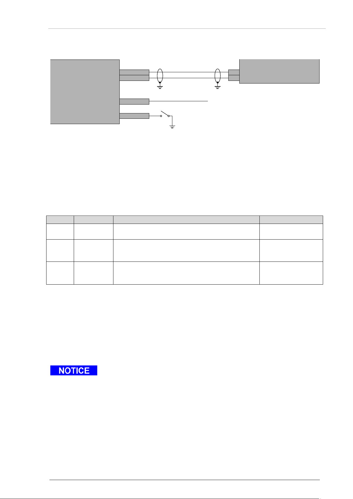
Becker Avionics
Installation
2.9.2.2 Software Update – Laboratory Installation
Value
Option
Description
Connect P1-44 to
0
Disable
Use with installations where Weight-on-Wheels
GND
1
Enable,
Use with installations where Weight-on-Wheels
GND
2
Enable,
Use with installations where Weight-on-Wheels
supply ( +28 V)
When in-field loading of software is enabled, the equipment does not perform
CCANP0
CCANN0
CIX14
P2-40
CIHL0 P1-44
Update Control
closed=enable
*
Length ≤ 2 m
P1-39
P1-38
CAN-H
CAN-L
BXT6513-(XXX)
Software Data Loader
(ARINC 826)
* Ground sensor: Provide the ground sensor connection depending on ground sensor configuration
see "Figure 29: Table – Ground Sensor Connection for Software Update (Laboratory)", page 65.
• Provide that the device and the software data loader match with CANbus speed settings.
• Detailed information about r equire d equi pment, wiring, FLS interface and update
procedure can you find in "FLS Manual" (Field Loadable Software) included in accessories
FLS6500-BXT Kit; see "Order Code" pag e 32.
• It is recommended as a minimum to perform "Mode S ground test (for details see "Mode S
Ground Test", page 71).
Figure 28: Software Update – Laboratory Installation
Software Update
sensor, strut switch, etc. is not installed.
active low
sensor, strut switch, etc. provides a "contact to
electrical ground" state when on the ground.
active high
Details see "FLS Manual" (Field Loadable Software) included in accessories FLS6500-BXT Kit; see "Order Code" page 32.
Figure 29: Table – Ground Sensor Connection for Software Update (Laboratory)
sensor, strut switch, etc. provides a "contact to
electrical power" state when on the ground.
The equipment enables Field Loadabl e Software (FLS) only at power-on when following
conditions are provided:
• FLS function enable input is active.
• If "Weight-on-Wheels" input reports "on-the-ground" state see "Figure 29: Table – Ground
Sensor Connection for Software Update (Laboratory) page 65.
normal operations.
Details see "FLS Manual" (Field Loadable Software) included in accessories FLS6500-BXT Kit; see "Order Code" page 32.
To return to normal operation, deactivate FLS input and restart the device.
DV15104.3 Issue 06 September 2018 BXT6500 Series 65
Page 66
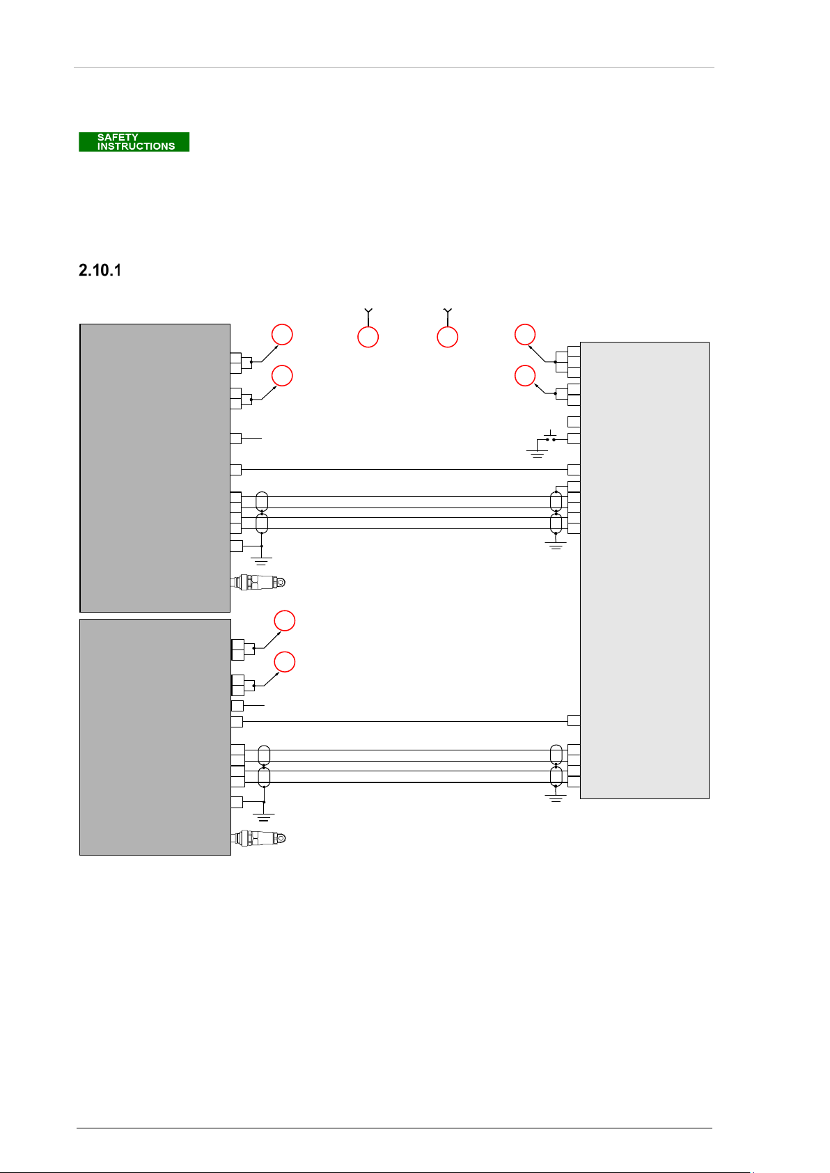
Installation
Becker Avionics
Aircraft Wiring
Installation of the device varies according to aircraft and equipment design. It is
A
B
A
B
A
B
A
B
BXT65
Transponder1
G7614
Controller
Power In+
Power In GND
Power In+
Power In+
Ext IDENT In
Aircraft GND
Dual Select In
Remote REPLAY
XPDR Control Port A Line A
XPDR Control Port A Line B
XPDR Data Port A Line A
XPDR Data Port A Line B
GND
ARINC 429 Out 1A
ARINC 429 Out 1B
ARINC 429 In 1A
ARINC 429 In 1B
ARINC 429 Out 2A
ARINC 429 Out 2B
ARINC 429 In 2A
ARINC 429 In 2B
GND
GND
GND
16
17
7
6
19
2
23
22
38
5
4
11
10
6
7
13
12
P1
32
33
41
21
32
24
44
1
2
3
Aircraft Power
+28 VDC
Aircraft Ground
GND
XPDR Standby Standby (not) / ON 1
26
Standby (not) / ON 2
XPDR Reply
twisted pair, shielded
twisted pair, shielded
BXT65
Transponder2
19
2
23
22
P1
Power In+
Power In GND
16
17
32
33
External Memory
EM
Ext. MEM Used
GND
14
6
XPDR Standby
7
XPDR Reply
twisted pair, shielded
twisted pair, shielded
XPDR Control Port A Line A
XPDR Control Port A Line B
XPDR Data Port A Line A
XPDR Data Port A Line B
External Memory
EM
Ext. MEM Used
GND
14
2.10 Aircraft Wiring
therefore only possible to provide general guidelines in this section.
It is in the installers responsibility to verify pin numbers on equipment
BXT65XX (dual) with Control Device G7614
manufactured by other than Becker Avionics.
Figure 30: BXT65XX (dual) with Control Device G7614 (Gables)
66 BXT6500 Series DV15104.3 Issue 06 September 2018
Page 67
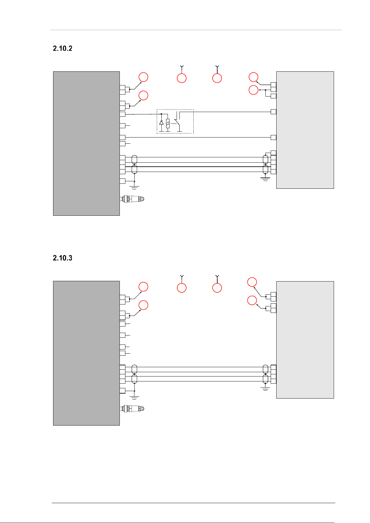
Becker Avionics
Installation
BXT65XX with Control Device KFS 578A
A
B
A
B
A
B
BXT65
Transponder1
KFS 578
A
Controller
Power In+
Power In GND
Power In+
Aircraft GND
Transponder 1 Fail DSC
XPDR Control Port A Line A
XPDR Control Port A Line B
XPDR Data Port A Line A
XPDR Data Port A Line B
ARINC 429 Common
ARINC 429 Out 1A
ARINC 429 Out 1B
ARINC 429 In 1A
ARINC 429 In 1B
GND
16
17
15
6
19
2
23
22
1
7
8
3
4
External
Memory
EM
P1
P5781
P5782
32
33
12
19
7
1
2
Ext. MEM Used
14
Aircraft Power
+28 VDC
Aircraft Ground
GND
XPDR Standby Standby (not) / ON
XPDR Status
44
Weight on Wheel Sensor
7
XPDR Reply
twisted pair, shielded
Signal inverter
(example)
twisted pair, shielded
Master (not) / Slave
A
B
A
B
A
B
BXT65
Transponder1
GTN 750
GPS
Power In+
Power In GND
Power In+
Aircraft GND
GNSS Data Line A
GNSS Data Line B
Time Mark Line A
Time Mark Line B
ARINC 429 Out 1A
ARINC 429 Out 1B
Time Mark Out A
Time Mark Out B
GND
16
17
15
6
20
3
13
12
10
29
3
22
External
Memory
EM
P1
P1001
32
33
77
78
19
20
Ext. MEM Used
14
Aircraft Power
+28 VDC
Aircraft Ground
GND
XPDR Standby
XPDR Status
44
Weight on Wheel Sensor
7
XPDR Reply
twisted pair, shielded
twisted pair, shielded
GND
Aircraft Wiring
Figure 31: BXT65XX with Control Device KFS 578A (BendixKing)
BXT65XX with GPS Device GTN750
Figure 32: BXT65XX with GPS Device GTN750 (Garmin)
DV15104.3 Issue 06 September 2018 BXT6500 Series 67
Page 68
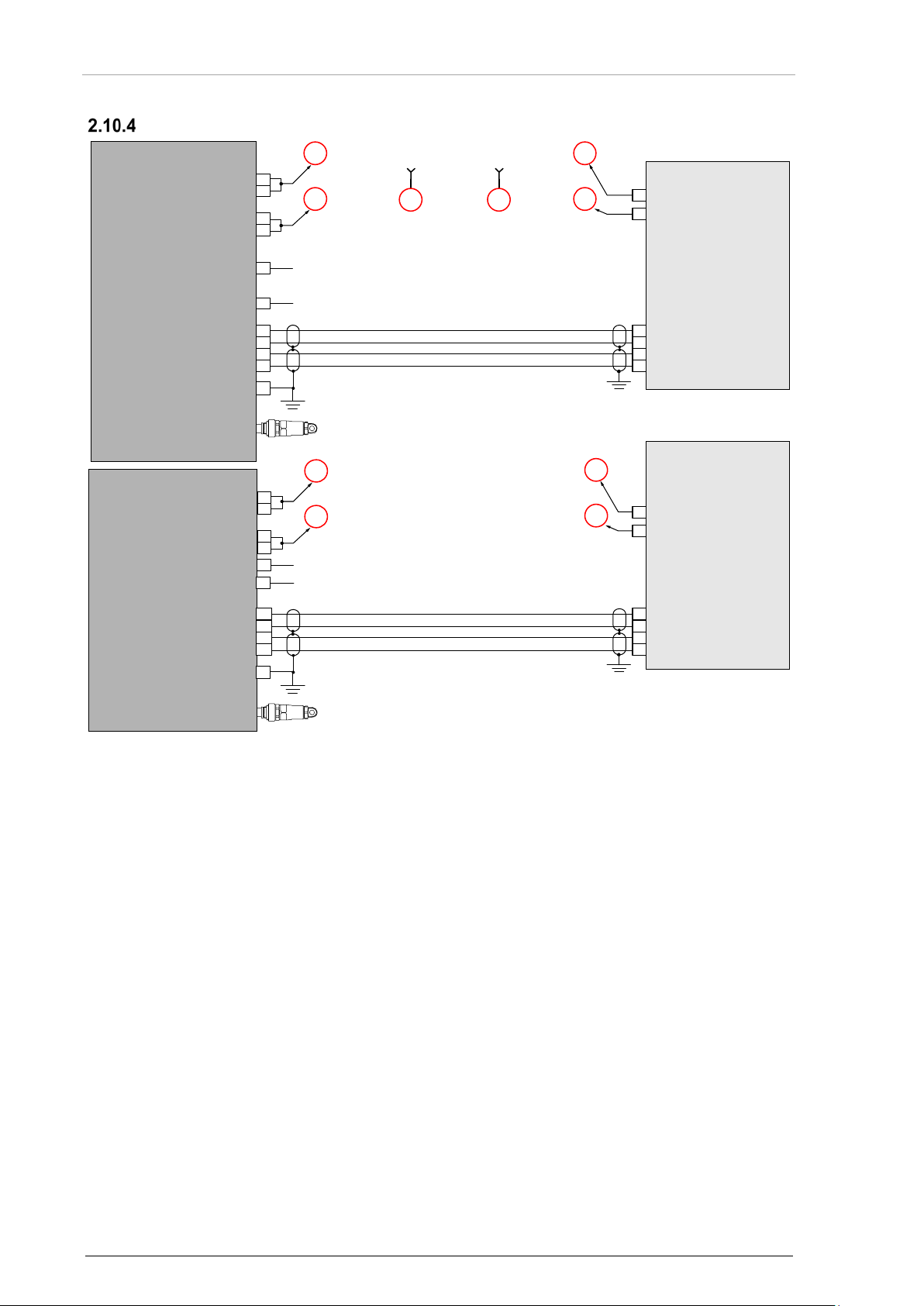
Installation
Becker Avionics
Aircraft Wiring
A
B
A
B
A
B
A
B
A B
BXT65
Transponder1
BXT65
Transponder
2
1203C
GPS
1
1203C
GPS 2
Power In+
Power In GND
Power In+
Aircraft GND
GND
16
17
7
6
20
3
13
12
14
13
3
4
External Memory
EM
P1
P1
P1
32
33
Power In+
Power In GND
16
17
32
33
2
1
Power In+
Aircraft GND
P1
2
1
Ext. MEM Used
GND
14
External Memory
EM
Ext. MEM Used
GND
14
Aircraft Power
+28 VDC
Aircraft Ground
GND
XPDR Standby
6
XPDR Standby
XPDR Reply
7
XPDR Reply
twisted pair, shielded
twisted pair, shielded
twisted pair, shielded
twisted pair, shielded
Out A
Out B
Time Mark
P
Time Mark N
GNSS Data Line A
GNSS Data Line B
Time Mark Line A
Time Mark Line B
GNSS Data Line A
GNSS Data Line B
Time Mark Line A
Time Mark Line B
Out A
Out B
Time MarkP
Time Mark N
20
3
13
12
14
13
3
4
BXT65XX (dual) with GPS Devices 1203C
Figure 33: BXT65XX (dual) with GPS Devices 1203C (Freeflight)
68 BXT6500 Series DV15104.3 Issue 06 September 2018
Page 69
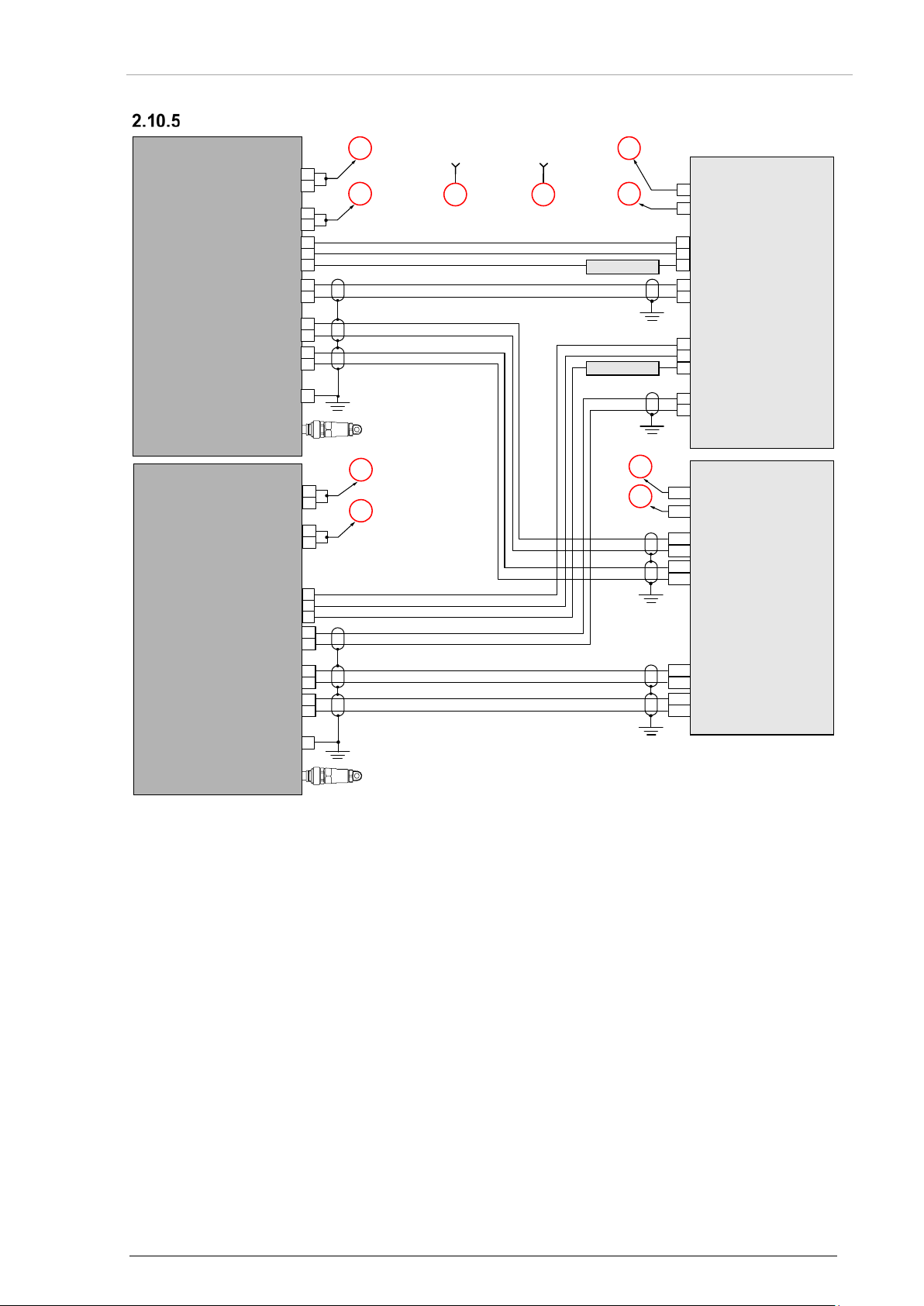
Becker Avionics
Installation
BXT6553 (dual) with Control & TCAS Device CTA-81A, TPA-81A
A
B
A
B
A
B
A
B
A B
BXT65
Transponder1
BXT65
Transponder2
CTA-81A
Controller
TPA-81A
TCAS
Power In+
Power In GND
Power In+
Aircraft GND
16
17
44
6
14A
14B
External Memory
EM
P1
P2
P1
P1
P1
P2
P1
32
33
Power In+
Power In GND
16
17
32
33
2
1
Power In+
Aircraft GND
RMP
Ext. MEM Used
GND
GND
GND
14
External Memory
EM
Ext. MEM Used
GND
14
Aircraft Power
+28 VDC
Aircraft Ground
GND
XPDR Standby
15
15
7
20
XPDR System Status
WoW
44
6
XPDR Standby
15
XPDR System Status
WoW
twisted pair, shielded
twisted pair, shielded
twisted pair, shielded
twisted pair, shielded
twisted pair, shielded
Signal Inverter
Signal Inverter
twisted pair, shielded
XPDR 429XMIT A
XPDR 429XMIT B
14H
14J
XPDR 429RCV A
XPDR 429RCV B
15J
15K
XPDR 429XMIT A
XPDR 429XMIT B
14F
14G
XPDR 429RCV A
XPDR 429RCV B
XPDR Control Port A Line A
XPDR Control Port A Line B
ARINC 429 Out A
ARINC 429 Out B
GND
STANDBY 1
XPDR FAIL 1
15
7
12
GND
STANDBY 2
XPDR FAIL 2
19
2
TCAS Data Port A
TCAS Data Port B
31
48
TCAS Interface Line A
TCAS Interface Line B
10
9
P2
XPDR Control Port A Line A
XPDR Control Port A Line B
19
2
TCAS Data Port A
TCAS Data Port B
31
48
TCAS Interface Line A
TCAS Interface Line B
10
9
22
23
ARINC 429 Out A
ARINC 429 Out B
22
23
GND
GND
Aircraft Wiring
DV15104.3 Issue 06 September 2018 BXT6500 Series 69
Figure 34: BXT6553 (dual) with Control & TCAS Device CTA-81A, TPA-81A
Page 70

Installation
Becker Avionics
Post Installation Check
2.11 Post Installation Check
Once the device is installe d com pletely a test proc edure shal l be started t o verify system f unctionalit y.
Ensure compliance with authority requir ed procedures. The f ollowing text provide s guidance for s uch
tests.
Mechanical Installation and Wiring Check
• Verify all cables are securely fixed and shields connected properly to signal ground.
• Check the movement of aircraft controls to verify there is no interference.
• Verify all screws are tight, check if all connections are mechanically secured.
Power Supply
• Check the power supply lines and confirm correct polarity. Don´t apply reverse voltage!
• Confirm that the aircraft power supply is within the specified limits, with and without a
running engine.
• Check LEDs (see "Meaning of Status LEDs" page 38).
Antenna Check
• Applying portable reflectometer or network analyzer measure the voltage standing wave
ratio (VSWR) at the transponder end of antenna aircraft installation.
• The measured VSWR at frequencies 1030 MHz and 1090 MHz shall not exc eed 1.5:1 .
70 BXT6500 Series DV15104.3 Issue 06 September 2018
Page 71

Becker Avionics
Installation
Post Installation Check
Aircraft System
Function
OK
NOT OK
DME
Audio
Generators / Inverters
GPS System
Compass 1
ADF
VHF / NAV 1 all channels
VHF / NAV 2 all channels
Marker Receiver
Motor(s)
Engine Instruments
Storm scope
Air Data Computer
Autopilot and Servos
Interference Check
• Check the device while engine is running and powered on all other avionics/ electrical
systems on the aircraft, to verify that no significant interference exists.
• Check also that the device does not cause significant interference with other systems.
The installer ´s s tandar d tes t proc edure m a y be used for the inter fer ence chec k a nd t he f ollowing ta ble
can be taken as a referenc e. Depending on the individual avion ic systems installed in the aircraf t, it
might be necessary to extend the following checklist accordingly.
For the remaining avionic equipment repeat all interference checks during a flight and include all
equipment not previously checked out on ground.
Mode S Ground Test
After successful completion of the previously described post installation checks perform a Mode S
ground test. (Refer to FAR 43 Appendix F or EASA C S-ACNS). The part 145 co mpany approv ed test
protocol shall finally be used.
An experienced test s etup conf iguration shall a lso be arrange d, otherwise r efer to the user instruction
of your specific test equipment.
Error / Failure Indication
It is possible to read out and reset error flags. For details contact Becker Avionics Customer Service.
For details about Error / Failure List contact Becker Avionics Customer Service.
DV15104.3 Issue 06 September 2018 BXT6500 Series 71
Page 72

Installation
Becker Avionics
Post Installation Check
Blank Page
72 BXT6500 Series DV15104.3 Issue 06 September 2018
Page 73

Becker Avionics
Operating Instructions
Device Description
3 Operating Instructions
In this chapter you can read about:
3.1 Device Description ...................................................................................................................... 73
Device Assignment ........................................................................................................... 73
Packing, Transport, Storage ............................................................................................. 73
Scope of Delivery .............................................................................................................. 73
Type Plate ......................................................................................................................... 73
3.2 Start-up ........................................................................................................................................ 74
Built In Tests (BIT) ............................................................................................................ 74
Extended Temperature ..................................................................................................... 74
3.3 Operating..................................................................................................................................... 74
Operating with OEM Controller ......................................................................................... 74
3.4 Read Out and Reset Error Flags ................................................................................................ 74
3.1 Device Description
BXT65XX is a remote-controlled device, which does not include a control panel. It can receive
commands and provides data through a set of interfaces.
Device Assignment
This manual is valid for the following devices:
• See page 36
Packing, Transport, Storage
• See page 35.
Scope of Delivery
• See page 36.
Type Plate
• See page 37.
DV15104.3 Issue 06 September 2018 BXT6500 Series 73
Page 74

Operating Instructions
Becker Avionics
3.2 Start-up
Built In Tests (BIT)
BXT65 series has advanced Built-In-Test. It monitors most of internal circuits against failures. In
addition BIT monitors some external (installation) conditions to increase reliability. There are three
types of BIT implemented:
• PBIT (performed after Power ON the device).
The test routine PBIT checks:
o System integrity,
o Software integrity,
• IBIT (initiated by special command via ARINC protocol).
The test routine IBIT checks:
o Transmitter operation
• CBIT (which continuously check operation).
The test routine CBIT checks:
o Reply transmissions,
o Squitter transmiss ions,
o Transponder receiver operation,
o Interfaces operation,
o System integrity,
o Equipment temperature,
o Internal voltages.
Extended Temperature
The BXT6553 contains an internal heater which heats the device(s) at low temperatures.
• In case the internal temperature is below -40 °C during power-on of the device(s), the
transponder remains switched off.
• As soon as the heater has increased the temperature above -40 °C the transponder is
switched on.
o During this period the transponders is inoperable and will supply an XPDR Fail signal.
• This period takes at maximum 20 minutes at nominal supply voltage.
3.3 Operating
Operating with OEM Controller
For detailed information please refer to the manual of the respective OEM product.
3.4 Read Out and Reset Error Flags
It is possible to read out and reset error flags.
This can be done b y the connected O EM product, for detailed inform ation please refer to the manua l
of the respective connected OEM product.
74 BXT6500 Series DV15104.3 Issue 06 September 2018
Page 75

Becker Avionics
Operating Instructions
Read Out and Reset Error Flags
Blank Page
DV15104.3 Issue 06 September 2018 BXT6500 Series 75
Page 76

Index
Becker Avionics
4 Index
Abbreviations .................................................. 8
Accessories .................................................. 32
Additional Conditions of Utilization ............... 11
ADS-B ........................................................... 19
Aircraft Wiring ............................................... 66
Antenna Installation ...................................... 43
ARINC 429 .................................................... 21
Associated Device s ...................................... 16
BIT ................................................................ 74
Built In Tests ................................................. 74
Conditions of Utilization ................................ 11
Connector 1 .................................................. 51
Connector P1 ................................................ 47
Connector P2 ................................................ 49
Device Assignment ................................. 36, 73
Dimensions ................................................... 44
Diversity ........................................................ 18
Hardware Configuration ................................ 54
In-field loading functionality .......................... 64
We reserve the right to make technical changes.
The data correspond to the current status at the time of printing.
© by Becker Avionics GmbH / all rights reserved
*** End of the Document ***
Installation Check .......................................... 70
Mode S .......................................................... 18
Mounting Requirements ................................ 39
Non-Warranty Clause ................................... 11
Operation Instructions ................................... 73
Order Code ................................................... 32
PC Requirements .......................................... 64
Pressurised cabin.......................................... 43
Radiation risk ................................................ 43
Reset Error Flags .......................................... 74
Software Configuration ................................. 63
Software Data Plate ...................................... 38
Software Update ........................................... 64
Type Plate ..................................................... 37
Units .............................................................. 10
Usage of the internal memory ....................... 63
Variants Overview ......................................... 16
Warranty Conditions ..................................... 11
76 BXT6500 Series DV15104.3 Issue 06 September 2018
 Loading...