

Page 1

VH F Grou nd Stat ion
TG480-(025)-(XX)
Installation and Operation
M a n u a l
I ss ue 1 A pr il 2 00 7
B E C K E R A V I O N I C S • 1 0 3 7 6 U S A T o d a y W a y • M i r a m a r , F L 3 3 0 2 5
Ph on e 95 4- 450 -3 137 • F a x 9 5 4 - 4 5 0 - 3 2 0 6
T G4 80 -( 02 5) -( X X)
Page 2
FIRST ISSUE AND CHANGES
Issue . . . 1 . . . . April 2007
LIST OF EFFECTIVE PAGES
Page No.: Date : Page No.: Date :
Title
1 -I - 1-II
1-1 - 1-8
2-I - 2-II
2-1 - 2-7
3-I - 3-II
3-1 - 3-25
04/07
04/07
04/07
04/07
04/07
04/07
04/07
© 2007 by Becker Avionics, Inc.
All rights reserved
Page 3

TG480-(025)-(XX)
Table of contents
Section 1 GENERAL INFORMATION Page
1.1 Introduction 1-1
1.2 Purpose of equipment 1-1
1.3 General description 1-1
1.3.1 Short description CORE Module 1-2
1.4 Technical Data 1-4
1.4.1 Technical data general, power supply 1-4
1.4.2 Technical data environmental 1-5
1.4.3 Technical data receive 1-5
1.4.4 Technical data transmitter 1-6
1.4.5 Technical data mechanical 1-6
1.4.6 Technical data battery operation (option 101) 1-7
1.4.7 Option 2-wire remote control (option 102) 1-7
1.4.8 Option multi-wire remote control (option 103) 1-7
1.4.9 Option tape recorder control (option 104) 1-7
1.4.10 Scope of delivery 1-8
1.5 Accessories 1-8
TG480XX.01 Issue 04/07 1-I
Page 4

TG480-(025)-(XX)
INTENTIONALLY BLANK
1-I TG480XX.01 Issue 04/07
Page 5
TG480-(025)-(XX)
Section 1 GENERAL INFORMATION
1.1 Introduction
This manual TG480XX.01 describes the VHF ground station
TG480-(025)-(XX).
The manual TG480XX.01 "Installation and Operation" contains the following sections :
Section DV 480XX.01
1 General Information X
2 Installation X
3 Operation X
1.2 Purpose of equipment
The VHF ground station
TG480-(025)-(XX) is a fixed ground station for speech communications in the
VHF frequency range of 118.000 MHz to 136.975 MHz.
The ground station is designed for airport and airfield use and can be used as a main transceiver on
landing fields and as a standby unit on airports and for special tasks within the scope of air traffic
control.
1.3 General description
The VHF ground station is designed for mounting in 19-inch rack systems or in an ATC desk.
The VHF ground station is designed to operate on a AC supply voltage of 115 V or 230 V ± 10% /50-
60 Hz. In DC operation, the VHF ground station is designed to operate on a voltage of 13.75 V
[TG480 - (10) or 24V, TG480 - (20), TG480 -(50)].
The control circuit switches over to external DC voltage if the AC voltage supply fails. If an internal
battery is fitted to provide an emergency power supply, it will still be possible to maintain T/R
communication for several hours if the AC and external DC supplies fail. The necessary charging
circuit for the battery is located inside the TG480 - ( ).
TG480XX.01 Issue 04/07 Page 1-1
Page 6

TG480-(025)-(XX)
GENERAL DESCRIPTION
1.3.1 General description of CORE Module
A. The VHF transceiver has been developed as a single block unit. The dimen-
sions correspond to the standard instrument diameter of 58 mm.
All controls and indicators are located on the front panel.
The rear of the unit holds the equipment connector and the antenna socket.
B. After it is switched on, the unit performs a self test. All segments of the display
flash during the self test. If faults are detected, the LCD (liquid crystal display)
displays a fault code for approximately five seconds. The VHF transceiver then
automatically activates the mode set before it was switched off.
C . The VHF transceiver is fitted with a single superheterodyne receiver. A squelch
(muting) circuit suppresses transmitters or disturbances below a certain field
strength. The switching threshold can be set. The squelch function can also be
switched off.
D . The transmitter is designed to be wideband over the 118.000 MHz to
136.975 MHz range. The transmitter output power is ≥ 5 Watt. The sidetone is
automatically switched to the headphone output during transmission.
E. The oscillator frequency of the receiver and the the transmitting frequency of
the transmitter are generated by a VCO (voltage controlled oscillator). This is
monitored by a digital frequency evaluation circuit. This digital frequency
processing operates in conjunction with a microprocessor.
F. The microphone inputs are designed for both dynamic and standard microphones.
The inputs are connected to a dynamic volume compressor which keeps the
modulation voltage constant over a wide input voltage range.
G . The frequency indication is by means of a liquid crystal display (LCD). The
required operating frequency is set using the MHz and kHz frequency selector
switches. The MHz rotary switch engages at 1 MHz steps and the kHz rotary
switch at 25 kHz steps. The VHF transceiver also contains a memory device
for storing 99 different frequencies which remain stored even with the unit
switched off without an auxiliary battery.
1-2 TG480XX.01 Issue 04/07
Page 7

TG480-(025)-(XX)
H. The VHF transceiver also contains a monitor ing sta ge for the supply voltage
which is activated when the VHF transceiver is switched on. If the supply
voltage drops below 10.5 V, the segments of the LCD begin to flash.
I. In the mode 3, the supply voltage and temperature is displayed in the bottom
line of the LCD.
J. The AF auxiliary input enables AF signal switching of auxiliary units in the air-
craft. The switched AF signals can, however, only be monitored in the reception
mode.
K. If illumination of the LCD is required, this can be connected either directly to the
supply voltage or via a dimmer.
L. The scan function can be switched on in the service mode and called up in
mode 2. The active frequency is shown in the top line of the display and the
bottom line shows the associated storage channel with the preset CS. In the
scanning mode the stored frequencies in the storage channels are scanned in
succession at 200 ms intervals. When an evaluatable reception signal is found,
the VHF transceiver remains on this frequency until an evaluatable reception
frequency is no longer present. It then begins to scan all the stored frequencies
again in 200 ms intervals. In the service mode, the hold time between the end
of an evaluatable signal and the continuation of the scanning of the next channels can be set to between 0 and 60 seconds.
M. Spe cial functions
VHF transceiver contains some special functions which can be set in the
service mode.
l Adjustment of volume IC, sidetone, AF auxiliary and the sensitivity of dy-
namic microphone.
l The switch-on threshold of the squelch can be set in the service mode.
l The frequency setting can be inhibited. The VHF transceiver then opera-
tes onlH.The VHF transceiver also contains a monitoring stage for the supply voltage.
l The storage of frequencies in the storage channels can be inhibited.
l Stored frequencies can be erased.
l Access to the service mode can be interlocked with a 4-digit password.
l The scan function can be switched on.
TG480XX.01 Issue 04/07 Page 1-3
Page 8

TG480-(025)-(XX)
1.4 Technical data
1.4.1 Technical data general, power supply
AC-Operating voltage 115 V or 230 V ± 10% 50/60 Hz
DC-Operating voltage
TG480 - (10) 12 V . . . 16 V TG480
TG480 - (20), TG480 - (50) 24 V +20% -10% Current
consumption at 115 V AC
max. Rx = 65 mA
TG480 - (05)
max. Tx = 300 mA
TG480 - (10) max. Rx = 250 mA
max. Tx = 1,5 A
TG480 - (20) max. Rx = 250 mA
max. Tx = 1,8 A
Current consumption at 230 V AC
TG480 - (10) max. Rx = 170 mA
max. Tx = 0,9 A
TG480 - (20) max. Rx = 170 mA
max. Tx = 1.1A
TG480 - (50) max. Rx = 170 mA
max. Tx = 3A
Current consumption at 13,75 V DC
TG480 -(10) max. Rx = 200 mA
max. Tx = 1800 mA
Current consumption at 24 V DC
TG480 - (20) max. Rx = 200 mA
max. Tx = 4,5 A
TG480 - (50)
max. Rx = 200 mA
max. Tx = 9,0 A
Battery int./U = 12.0 V (optional) max. Rx = 240 mA
max. Tx = 1800 mA
Fuse
PS 24V
DC 24V
DC-DC 15V
AC 120V
AC 120V Spare
15A
15A
5A
10A
10A
Protection against wrong polarity at DC external voltage
TG480XX.01 Issue 04/07 Page 1-43
Page 9

TG480-(025)-(XX)
Frequency range 118.000 MHz - 136.975 MHz
Frequency tolerance ≤ 15 ppm
Channel spacing 25 kHz
Number of channels 760
Number of channel memories 99
Antenna impedance 50 Ω
1.4.2 Technical data environmental
Operating temperature range - 15° C . . . + 50° C
Storage temperature range - 40° C . . . + 70° C
Humidity (operating) ≤ 95% / 40° C without condensation
Humidity (storage) ≤ 95% / 40° C
Operating altitude
Operating - 200 . . . 3500 m
Transport - 200 . . . 10000 m
1.4.3 Technical data receiver
Sensitivity
m = 60 % / 1 kHz ≤ 5 µV (EMF)
N
Selectivity
± 17 kHz ≥ 40 dB
± 25 kHz ≥ 60 dB
Intermodulation ≥ 65 dB
IF frequency 21.4 MHz
IF bandwith ≥ ± 8 kHz
S + N ≥ 1 0 dB
Squelch adjustable (dependant on carrier)
AF output power asym. (Speaker) ≥ 2 W 4 Ω (adjustable)
AF output power sym. (Headphone) ≥ 0.1 W 600 Ω (adjustable)
Distortion ≤ 10 %
Spurious emission - 57 dBm (2 nW)
Page 1-5 TG480XX.01 Issue 04/07
Page 10

TG480-(025)-(XX)
1.4.4 Technical data transmitter
Transmitter power output VSWR 1:1
TG480 - (10) ≥ 10W
TG480 - (20) ≥ 20W
TG480 - (50) ≥ 50W
Tolerable VSWR
2:1
Modulation type A3E
Modulation factor ≥ 80% and ≤ 100%
Distortion ≤ 10 %
≤ 15% TG480 - (50)
Duty cycle 1 minutes transmit- and
4 minutes receive mode
Carrier noise level ≥ 35 dB
Spurious emissions ≤ 54 dBm (4 nW)
Dynamic Mic.
≤ 2mV symm .
(dynamic compressor)
1.4.5 Technical data mechanical
Dimensions
Case
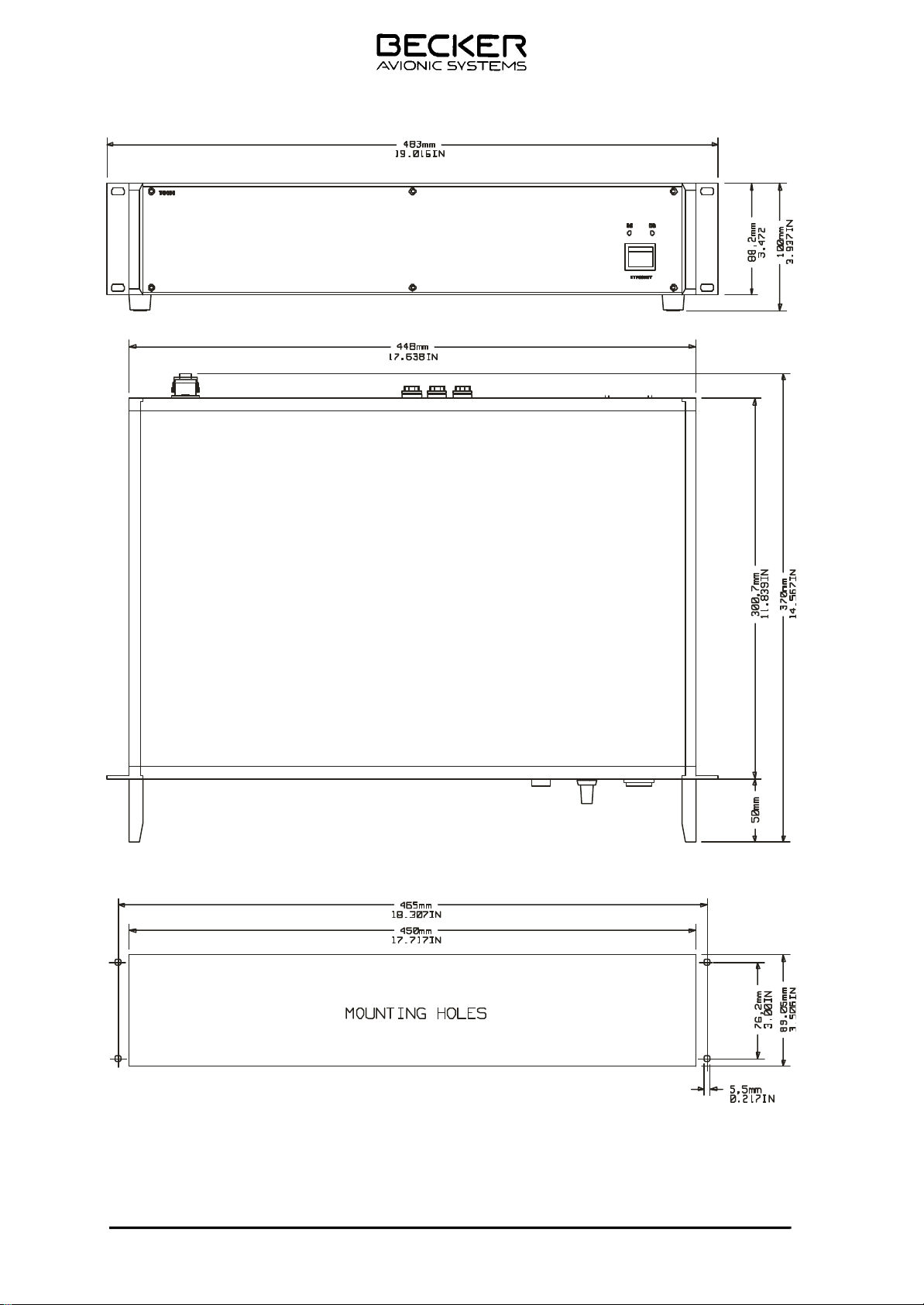
448 x 350 x 89 mm
19 Zoll unit
483 x 350 x 89 mm
Antenna connector N-female
Weight (without options) 78.5 kg
TG480XX.01 Issue 04/07 Page 1-6
Page 11

TG480-(025)-(XX)
1.4.6 Technical data battery operation (option 101)
Nominal voltage 12 V DC
Capacity of internal battery
transmit/receive ratio of 1 : 4 typ. 3 hrs.
transmit/receive ratio of 1 : 9 typ. 5 hrs.
standby mode typ. 8 hrs.
Number of internal batteries 1
Battery type Lead battery 2,2 Ah
1.4.7 Option 2-wire remote control (option 102)
Max. length of wire ≤ 10 km
Impedance 600 Ω
1.4.8 Option multi-wire remote control
Max. length of wire ≤ 100m
1.4.9 Option recorder control OP 104
Audio output recorder 100 mV at 47kΩ (adjustable)
Page 1-7 TG480XX.01 Issue 04/07
Page 12

TG480-(025)-(XX)
1.4.10 Scope of delivery
VHF ground station TG480 - (10 ) Stock no.: 940.437-926
or
VHF ground station TG480 - (20 ) Stock no.: 940.436-926
or
VHF ground station TG480 - (50 )
Stock no.: 940.435-926
Fuse 3.15 AT Stock no.: 788.074-392
Fuse 4 AT Stock no.: 769.304-392
Fuse 10 AT Stock no.: 912.109-392
Cable connector (DC connection)
Stock no.: 724.890-277
Mains cord (AC connection) Stock no.: 295.728-277
1.5 Accessories
Antenna connector (N-male) Stock no.: 716.502-277
Hand dyn. microphone with Stock no.: 344.214-951
cable with 5-pole DIN connector 1PM012
Shure 514B dyn. mike
Stock no.: 901.402-350
Lighting protection, IS-50NXCO Stock no.: 962.704-283
Antenna 1A049 Stock no.: 812.064-952
Notch-Filter Stock no.: 889.407-918
DTR 40-FD Remote Control (CPI) Stock no.: 919.442-951
DTP1-C, DC term. panel (CPI) Stock no.: 919.443-951
TG480XX.01 Issue 04/07 Page 1-8
Page 13

TG480 A - ( XX )
Table of contents
Section 2 INSTALLATION Page
2.1 Installation in a tower ATC desk 2-1
2.1.1 General 2-1
2.1.2 Pre-installation check 2-1
2.1.3 Visual inspection 2-1
2.1.4 Setting up the VHF-ground station 2-1
2.1.5 Installation of fuse for battery (Option 101) 2-2
2.1.6 Mechanical installation of VHF ground station in an ATC desk 2 - 2
2.1.7 Hints for installation of the VHF ground station in an ATC desk 2-3
2.1.8 Connection of external PTT switch or PTT foot switch 2-3
2.1.9 Installation of antenna system 2-3
2.1.10 Lightning protection 2-3
2.1.11 Grounding the VHF ground station 2-3
2.1.12 Over-voltage protection 2-3
2.1.13 Tuning Instructions for the co-location filter 2-3
2.2 Pin connection front / rear panel 2- 3
2.2.0 Pin connection service connector 2-3
2.2.1 Pin connection mike connector J 25 (MIC) 2-4
2.3 Pin connection rear side 2-4
2.3.1 Pin connection remote control J 19 (REMOTE CONTROL) 2 - 4
2.3.2 VHF tunable filter 2 - 4
2.3.3 Pin connection tape recorder connector J 23 (TAPE RECORDER) 2-5
2.3.4 DC EXT. INPUT connector wiring 2-5
Fig. 2-1 Mechanical installation 19-inch adaptors 2 - 2
Fig. 2-2 Installation wiring diagram tape recorder 2 - 5
Fig. 2-5 Dimensions TG480 - ( )
TG480XX.01 Issue 04/07 2-I
2 - 7
Page 14

TG480-(025)-(XX)
INTENTIONALLY BLANK
2-II TG480XX.01 Issue 04/07
Page 15

TG480-(025)-(XX)
Section 2 INSTALLATION
2.1 Installation in a Tower ATC desk
2.1.1 General
The VHF ground stati on can be incorporated in a tower air traf fic control desk depending on the type of
the latter. The following instructions thus apply only in a general way.
Caution
In stal la ti on and cab ling of the VHF ground sta ti on shall only be done by skil led avio nics
personnel.
Re mo val of the co vers of the VHF ground sta ti on and re pairs of this equip ment shall only
be done by skil led avio nics per son nel.
2.1.2 Pre-installation check
In spect the unit pri or to in stal ling the VHF ground sta ti on in an ATC desk, to estab lish whet her it has suf fe red da ma ge du ring trans por ta ti on.
2.1.3 Visual inspection
Be fo re com men cing ope ra ti on vi su al ly exa mi ne the unit pay ing par ti cu lar at ten ti o n to the fol lo wing de fects:
1. Dirt, dents, scrat ches, cor ro si on or bro ken at ta ching parts, da ma ged paint work on hou sing, parts of
the hou sing and pa nel.
2. Dirt or scrat ches on the iden ti fi ca ti on pla te, front pa nel, LCD or ins crip tions.
3. Dirt, bent or bro ken pins, dis pla ced in serts of plugs and so ckets.
4. Dirt and me cha ni cal da ma ge to pushbut tons and ope ra ting knobs.
2.1.4 Setting up the VHF ground station
The VHF ground sta ti on can be set up eit her flat or in a slant pla ne (using the col lap si ble legs) on a tab le.
Af ter set ting up the equip ment shall be con nec ted to a po ten ti al equa li za ti on bar via an
ear ting lead ha ving cross-section of 10 squa re mil li me ters. The earth ting con nec ti on is lo ca ted on the rear pa nel of the equip ment.
Be fo re con nec ting the ann ten na to the equip ment sta ti cal ly disch ar ge the an ten na and
the an ten na fee der line by con nec ting both the con nec tor hou sing and the in ner
con-ductor of the an ten na line to the earth ting con nec ti on on the rear pa nel of the equip ment.
TG480XX.01 Issue 04/07 Page 2-1
Page 16
TG480-(025)-(XX)
Con nect the mi cro pho ne to the mi cro pho ne jack.
If the equipment has option 101 incorporated, the attached fuse has to be installed in the
battery fuse holder (Refer to Installation of fuse for battery.
Connect the cable plug “DC extern” to the jack “DC extern” on the rear panel of the VHF
ground station. Connect the other end of the DC supply voltage.
CAUTION
Do not confuse the polari ty!
An ade qua te ly di men sio ned ca ble of 1,5 mm
2
and hig her shall be used for his pur po se
Con nect the supp lied po wer cord first to the VHF ground sta ti on and then to AC po wer
outlet.
NOTE
The re is no ON/OFF switch pro vi ded on the VHF ground sta ti on. If an ex ter nal supp ly vol ta ge, eit her AC or DC is ap plied, the VHF ground sta ti on is in the stand by mode. By me ans of the ON/STAND BY switch on the front pa nel the equip ment can be swit ched ON or
in the stand by mode. If a bat te ry is in stal led in the VHF ground sta ti on and the AC- and
DC-external supp ly vol ta ges are swit ching off and by mis ta ke the ON/STAND BY switch in
the ON po si ti on, the equip ment is run ning on the in ter nal bat te ry.
2.1.5 Installation of fuse for battery (option 101)
To prevent unintended switching ON of the VHF ground station during transport and thus discharging
the battery the fuse will be removed before shipping. Please insert the enclosed 12 amperes fuse into
the fuse holder no. 2 on the back panel of the VHF ground station.
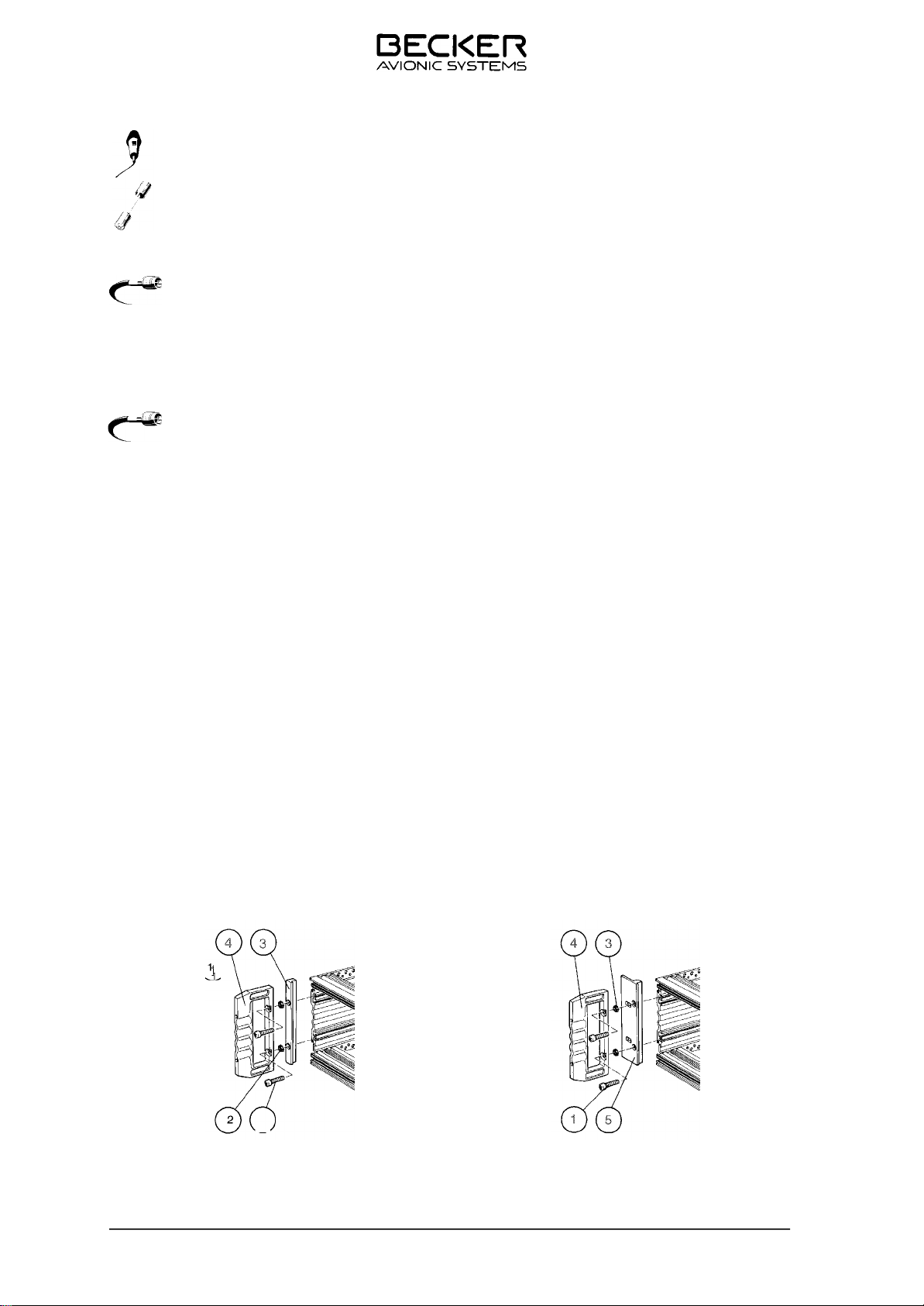
2.1.6 Mechanical Installation of the VHF ground station in an ATC desk
The 19-inch tab le mo del may be in stal led in an Air traf fic con trol desk at any time. By me ans of a 4 mm
Al len-type wrench re mo ve the for screws (1) and the hand les (4). Re fer to Fi gu re 2-1. Re mo ve the two
adap tors “FRONT” (3) and re pla ce them by the 19-inch adap tors (5). The 19-inch adap tors are supp lied with each unit.
Fig. 2-1 Me cha ni cal In stal la ti on 19-inch adap tors
Page 2-2 TG480XX.01 Issue 04/07
Page 17

TG480-(025)-(XX)
2.1.7 Hints for installation of the VHF ground station in an ATC desk
Re fer to 2.1.4.
2.1.8 Connection of external PTT switch or PTT foot switch
The PTT key can be con nec ted eit her to the mi cro pho ne jack on the front pa nel or to DB connector
on the rear pa nel.
Mi cro pho ne jack See fig. Jack J4
PTT DB connector Pin 4 PTT
Pin 5 GND
2.1.9 Installation of antenna system
For sa fe ty rea sons the an ten na sys tem should be in stal led only by spe cia list per son nel or a spe cia list
firm. The cor rect in stal la ti on and groun ding of the an ten na sys tem is an ess en ti al pre con di ti on for trou ble free functio ning of the VHF ground sta ti on.
2.1.10 Lightning protection
To pro tect the VHF ground sta ti on from light ning stri ke or sta tic disch ar ge at the an ten n a, a light ning
pro tec ti on ele ment is to be fit ted in the supp ly ca ble. The hou sing of the light ning pro tec ti on ele ment is
to be con nec ted at the groun ding ter mi nals via an ade qua te ly si zed ca ble to the po ten ti al equa li sa ti on
rail of the buil ding or ot her ground.
Light ning pro tec ti on ele ment with N stan dard ter mi nal and epla ce ab le gas disch ar ge cartridge.
Or der No. 887.870-277
Re pla ce ment car trid ge up to 40 W trans mit ter po wer
Or der No. 887.889-277
2.1.11 Grounding the VHF ground station
The groun ding ter mi nal (M 5 screw with nut) which is cle ar ly mar ked with the groun ding sym b ol is lo ca ted on the back. The VHF ground sta ti on is to be con nec ted via this ter mi nal to the po ten t i al equa li sa ti on rail of the buil ding or sys tem to pro vi de a low oh mic and low in duc ti ve con nec ti on. An ade qua te ly di -
2
men sio ned ca ble of 10mm
co lou red green/yel low shall be used for this pur po se.
Note:
The relevant safety precautions shall be observed.
2.1.12 Over Voltage Protection
The re is an over-voltage pro tec ti on functi on built-in. Af ter over-voltage pro tec ti on ac ti va tes, a mi ni mum
time lap se of 1 min. from the mo ment of swit ching off the in put is re qui red be fo re any in p ut can turn on
the supp ly again. Over-voltage pro tec ti on set ting is fi xed at 115% - 135% no mi nal.
TG480XX.01 Issue 04/07 Page 2-3a
Page 18
TG480-(025)-(XX)
2.1.13 Tuning Instructions for the co-loca er
Item Description:
The co-location lter is a two section tunable BPF. Helical resonators and variable capacitors make
up the resonant sections which have a tuning range from 116-150 MHz.
Tuning Instructions:
The co-location
not spe
ed. When units are to be tuned outside the factory, it is advisable to use a network or
lter is normally shipped tuned to a center frequency of 116 MHz, if the channel is
scalar analyzer set to the appropriate frequency range and span as required.
There are 2 adjustments that control the resonant frequency of the
lter. They are iden ed on the
envelope drawing as "C1" and "C2," which are capacitors. The only tool required is a small slotted
screwdriver. There is a protectiv
e cap over the capacitor with an access hole for a screwdriver.
Using the screwdriver, rotating the capacitor in a clockwise direction increases the capacitance of
that particular section, lowering the frequency of operation. Conversely, rotating the capacitor in a
counterclockwise direction decreases the capacitance of that particular section, increasing the
frequency of operation.
When tuning the
center frequency with a 5 or 10 mhz span. Depending on where the
lter to a spe c center frequency, it is convenient to set the analyzer to the desired
lter is presently tuned, adjust C1
accordingly until a peak in the response is noted on the analyzer at the desired center frequency.
Adjust C2 in a similar fas
hion un
til the bandpass response is cenetered and the return loss null is
about 18 dB. No other adjustments are required.
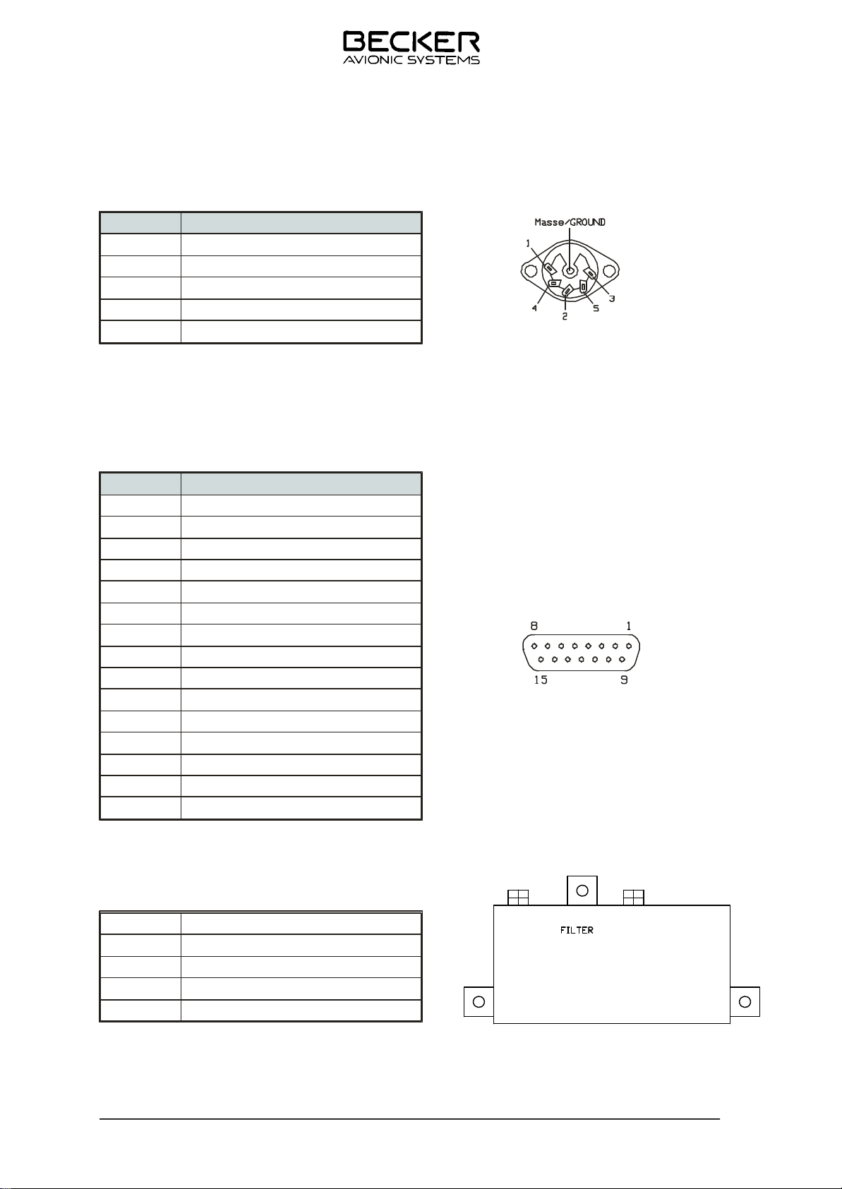
2.2 Pin con nec ti on front /rear pla te
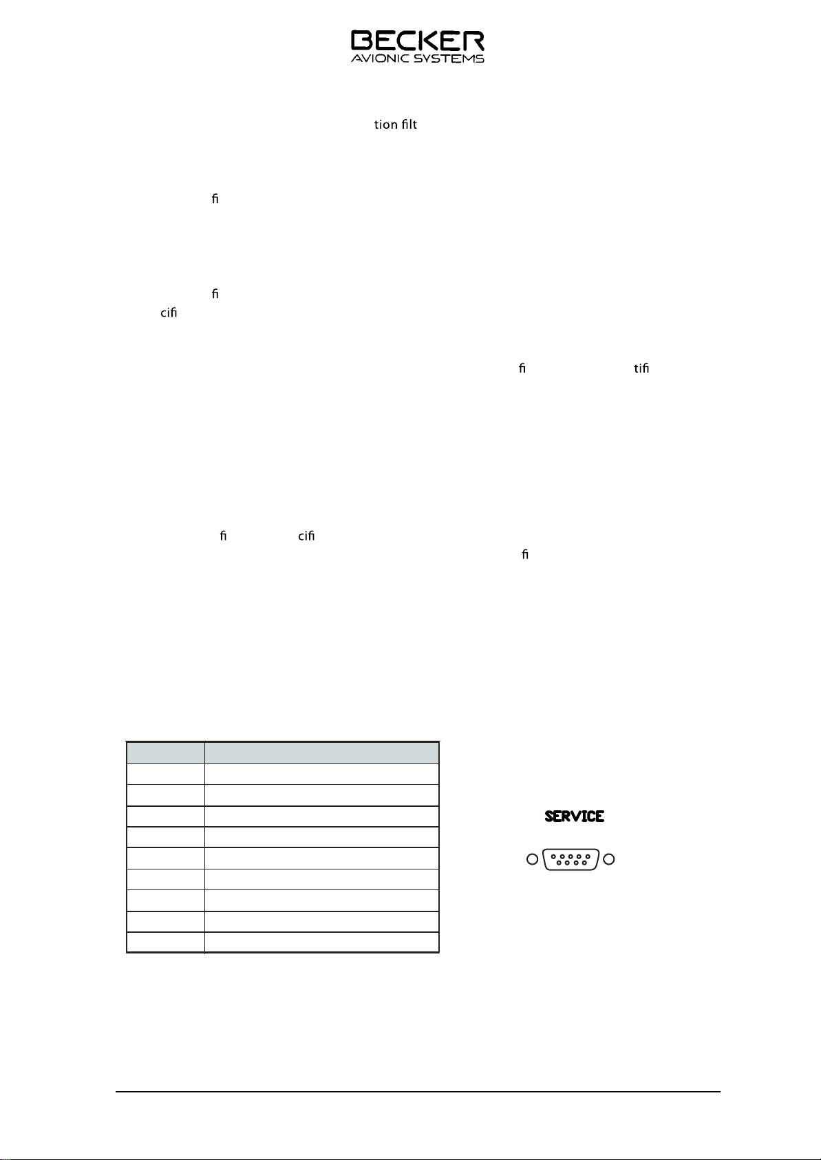
2.2.0 Service connector wiring
Pin
1 Vcc
2 TXD
3 RXD
4 SQL (COR)
5 GND
6
7 ALARM
8 V-FOR
9 V-REF
Description
RF Tx
5 1
15
7
Note: TG480 Series RS 232 Adapter must be used if Service port is to be used with a computer.
TG480XX.01 Issue 04/07 Page 2-3b
Page 19
TG480-(025)-(XX)
2.2.1 Pin connection mike connector J 25 (MIC)
Pin Description
1 GND
2 MIKE HI
3 HEADPHONE
4 MIKE LO
5 PTT
2.3 Pin con nec ti on rear side
2.3.1
Pin connection remote control J 19 (REM/REC/RS232)
Pin Description
1 + 15 VDC - Switched
2 Tx Data
3 Rx Data
4 PTT
5 GND
Rx Audio
6
7 Tx Audio
8 SQL -COR - Active Low
9 REC AF
10 AF GND
11 STD Mic
12 AF-HI
13 AF-LO
14 AF-ASYM
15 DC GND
2.3.2 VHF tunable Filter (Optional)
C1
C2
Description
C1 VHF tunable filter adjustment
C2 VHF tunable filter adjustment
VHF Tunable Filter
Page 2-4 TG480XX.01 Issue 04/07
Page 20
TG480-(025)-(XX)
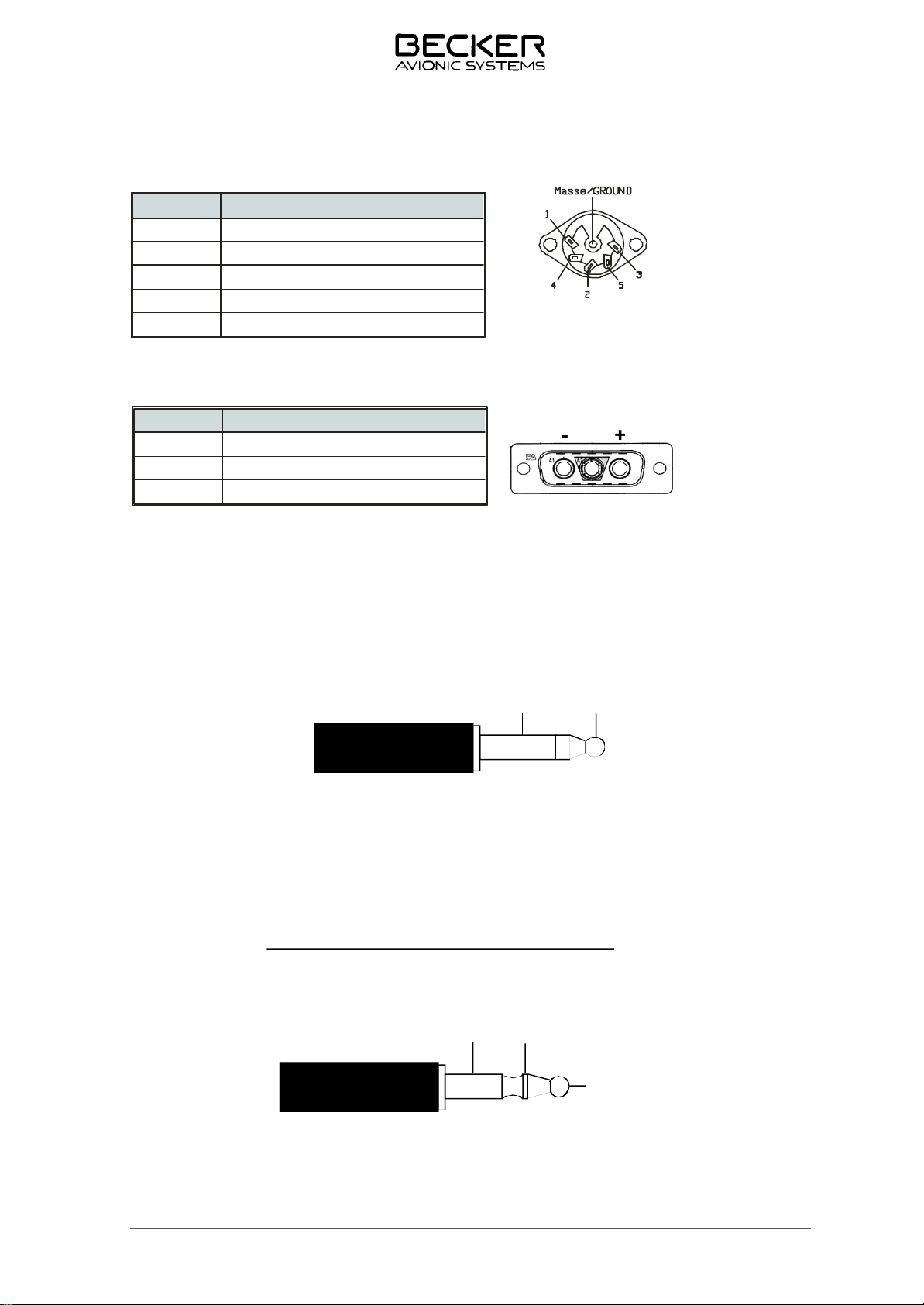
2.3.3 Pin connection recorder connector J 23 (RECORDER)
Pin D escri ption
1 A u d i o T a p e
2 GND
3 PTT 2
4 PTT 1
5 PTT 3
2.3.4 DC EXT. INPUT connector wiring
Pin no it pirc seD
1 - Negative
2 NC
3
+ Positive
Plug for MICRO jack (J3) (∅ 6 . 3 5 m m ) :
J K3 4 - EL N O ( 1 50 0 01 6 3) Pl u g P L 55 -3 0 0 ( 15 0 0 01 46 )
T h e l i st e n i ng i s v i a a 6 0 0 o h ms h ea d s e t a n d i t i s n o t r e qu i r e d t o k e ep t he e ar p h o ne s on d ur i n g t e st .
The output level can be set with the volume potentiometer.
PLUG FOR HEADSET JACK
Plug for MICRO jack (J4) (∅ 5 . 2 5 m m ) :
J K3 3 - EL N O ( 1 50 0 01 6 4) Pl u g P L 68 - 30 1 ( 150 00 14 5 )
I t a l lo w s t h e t r a n sm i t t er t o b e u s ed f ro m t h e f r o n t p a ne l . W h e n t h e o p er a t o r p r es s e s t h e m i ke
t r a n s m i s s i o n p u s h- b u t t o n h e c a n c o n t r o l t h e w h o l e u n i t i r r e s p e c t i v e o f t h e s i g n a l s t a t u s i n t h e
r e m o t e c o n t r o l p l u g w i t h t h e e x c e p t i o n o f t h e t r a n s m i s s i o n i n h i b i t i o n
T w o m i k e s e n s i t i v i t i e s a r e p o s s i b l e (see Paragraph 5.2).
Ground Micro
Ground AF
.
RF TEST Conn
trol of the
master oscillators
P.T.T. key
TG480XX.01 Issue 04/07 Page 2-5
PLUG FOR MICRO JACK
Page 21
TG480-(025)-(XX)
Front View
T op View
Fig. 2-5 Di men sions TG480 -( )
Page 2-6 TG480XX. 01 Issue 04/0 7
Page 22
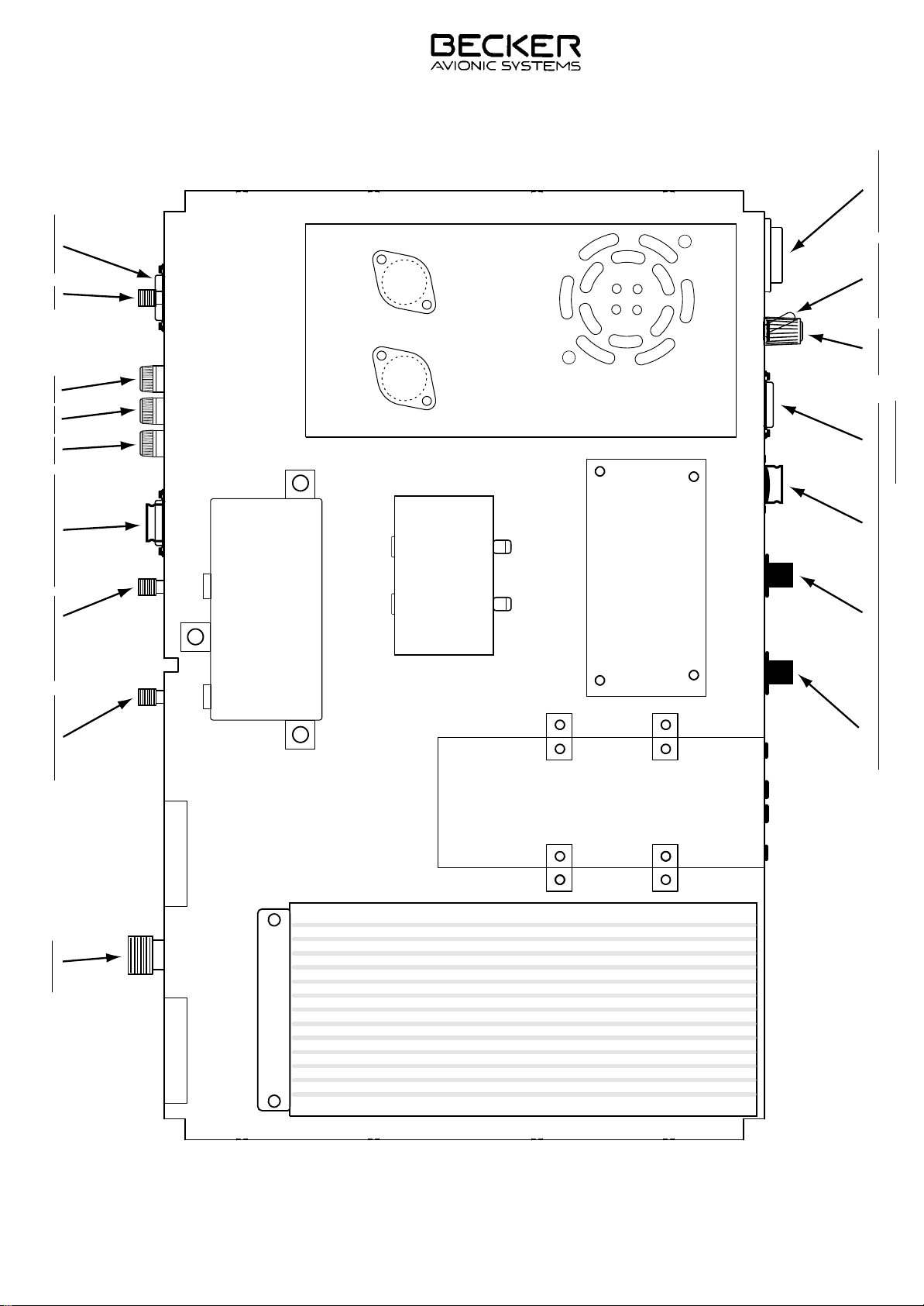
TG480 - ( XX
)
SPKR On-O
Power Supply
Reectometer
RF Filter
Filter - IN/OUT Filter - IN/OUT Recorder / Remote Fuse Fuse Fuse Aux DC Power
Switch Board
Volume Power On-O
Data Terminal
MHz Selector KHz Selector Mic/Phone Maintenance
Transcei ver
Antenna
RF Power Amplier
Page 23
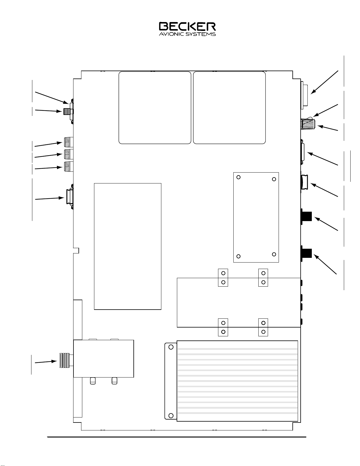
TG480-(10) Layout
TG480 - (XX)
)
Battery
Recorder / Remote Fuse Fuse Fuse Aux DC Power
RF Power Amplier
Battery
Switch Board
SPKR On-OVolume Power On-O
Data Terminal
Transceiver
Reectometer
Antenna
Power Supply
Battery Charger
TG480XX.01 Issue 04/07 Page 2-7a
MHz Selector KHz Selector Mic/Phone Maintenance
Page 24
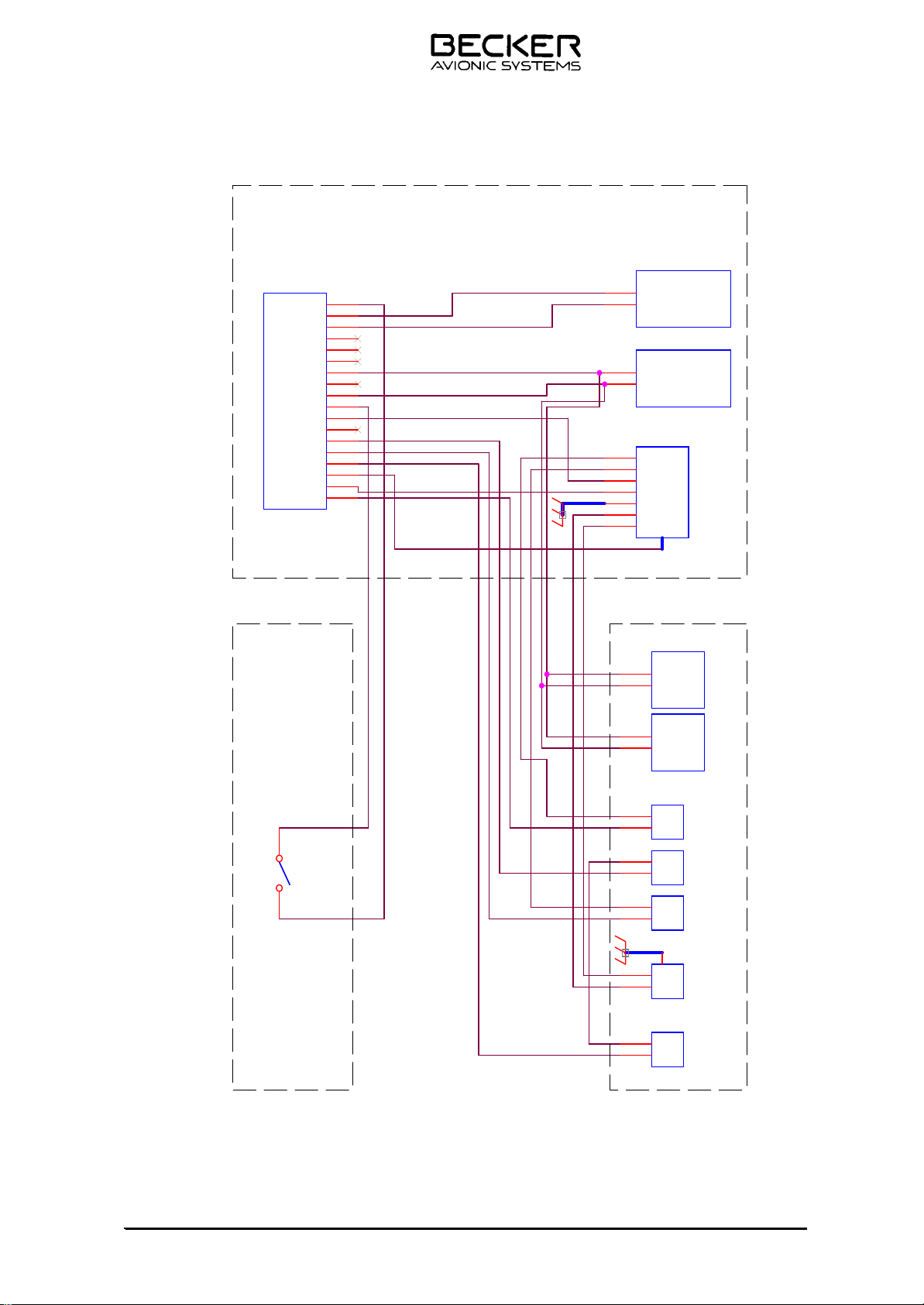
TG480 AC/DC Cabling
Cable #1
Cable #2
Cable #3
Cable #9
Cable #11
Cable #7
Cable #16
Cable #14
Cable #18
Cable #13
Cable #17
Cable #15
Cable #10
Rear Panel
Legend:
DC - Direct Current
AC - Alternating Current
PS - Power Supply
PA - RF Power Amplifier Input
Chassis
Front Panel
Switch BoardSwitch Board
1
2
3
4
5
6
7
8
9
10
11
12
13
14
15
16
17
18
RF PARF PA
+24V In
GND
Switch
ON/OFF
Switch
ON/OFF
+ 24V -
Connector
+ 24V -
Connector
+24V
GND
TransceiverTransceiver
+15V In
GND
FanFan
+24V In
GND
P.S.
Fuse
P.S.
Fuse
In
Out
DC
FuseDCFuse
In
Out
FanFan
+24V In
GND
Power SupplyPower Supply
+15V Out
+24V Out
-24V Out
+24V In
GND
AC-N
AC-L
DC-DC
Fuse
DC-DC
Fuse
In
Out
AC
Connector
AC
Connector
AC-L
AC-N
TG480XX.01 Issue 04/07 Page 2-8
Page 25
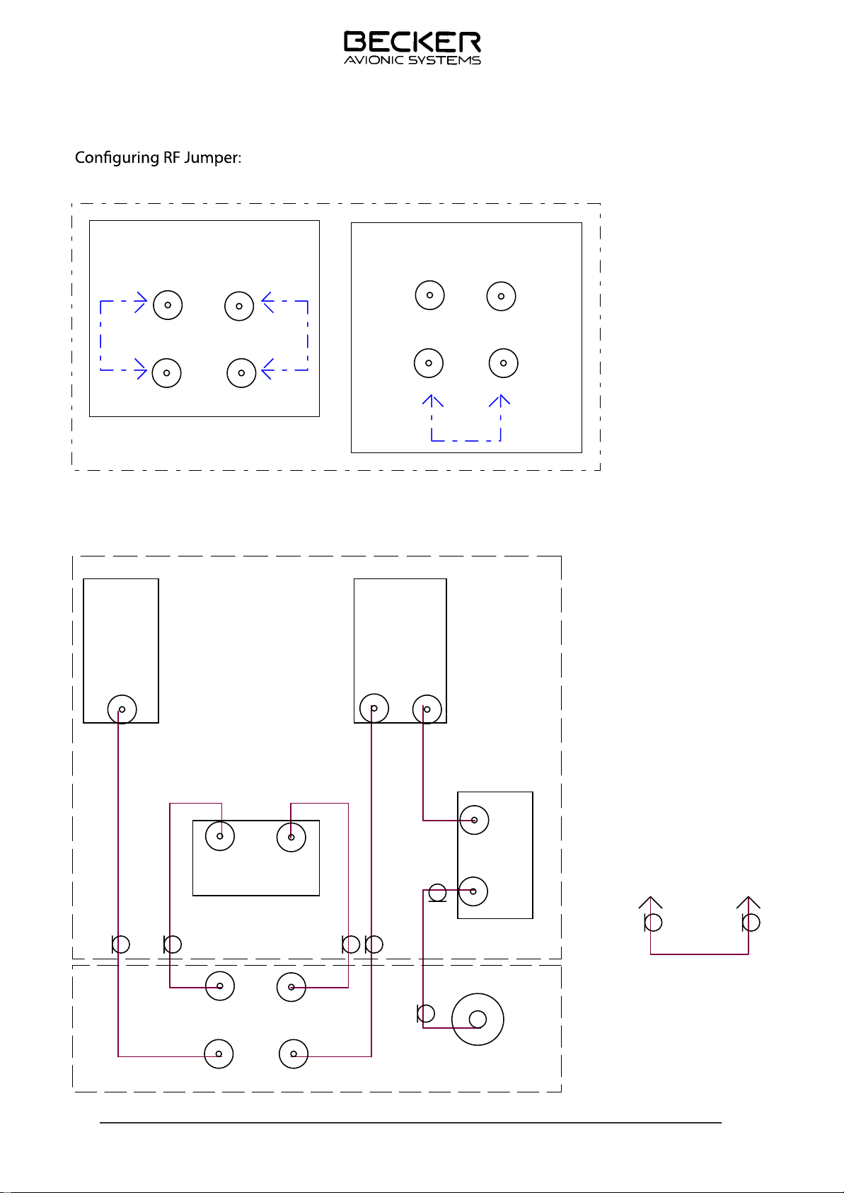
TG480-(025)-(XX)
Single Channel
Configuration
RF Cabling:
Trans
ceiver
J2 J1
AR PA
Multi Channel
Configuration
J2 J1
AR PA
Chassis
PA
RF
I/O
RF Cable #33
RF Cable #31
J1J2
RF FILTER
J2 J1
AR PA
RF
IN
RF Cable #34
RF Cable #32
RF
OUT
RF Cable #36RF Cable #35
ANT
Rear Panel
INOUT
RF JUMPER
Reflectometer
RF Cable #37
Legend:
J1 - RF Filter Port 1
J2 - RF Filter Port 2
AR - AR4201 Antenna Port I/O
PA - RF Power Amplifier Input
Page 2-9 TG480XX.01 Issue 04/07
Page 26

TG480-(025)-(XX)
Table of contents
Section 3 OPERATION Page
3.1 Controls and indicators 3-1
3.2 Meaning of symbols on controls and indicators 3-3
3.2.1 Over-voltage protection 3-3
3.3 Operating instructions 3-5
3.3.1 Switching on the VHF ground station 3-5
3.3.2 Transmit/receive mode 3-5
3.3.3 Jamming of transmit button 3-7
3.3.4 Flashing of the LCD 3-7
3.3.5 Operation of the mode 1 and 2 3-7
3.3.5.1 Mode 1 (standard mode) 3-9
3.3.5.2 Mode 2 (display of fixed frequencies in the various channels) 3-10
3.3.6 Service mode (equipment configurations) 3-14
3.3.6.1 Entering up the service mode 3-15
3.3.6.2 Setting the squelch threshold 3-15
3.3.6.3 Setting the sidetone level, if connected a Head set 3-16
3.3.6.4 Setting the audio auxiliary level 3-16
3.3.6.5 Setting the hold time in the scan function 3-18
3.3.6.6 Release the frequency setting (channel selection only) 3-18
3.3.6.7 Release the frequency storage 3-19
3.3.6.8 Erasing stored channel frequency 3-19
3.3.6.9 Setting the "channel start" scanning range 3-19
3.3.6.10 Setting the "channel end" scanning range 3-20
3.3.6.11 Entry of password to interlock the equipment configuration 3-20
3.3.6.12 Programming of acknowledgement signal 3-20
3.3.6.13 Setting the dynamic mike input sensitivity 3-20
3.3.6.14 Channel priority ON/OFF switch (option) 3-21
3.3.6.15 FSqL (no function) 3-21
3.3.6.16 Block speaker key (LSP) function ON/OFF 3-22
3.3.6.17 Indication the Software spec. no.: and changes status 3-22
3.3.6.18 Standard equipment configuration settings in the service mode 3-22
3.3.6.19 Exiting of the service mode 3-22
3.4 Safety instructions 3-25
TG480XX.01 Issue 04/07 3-I
Page 27
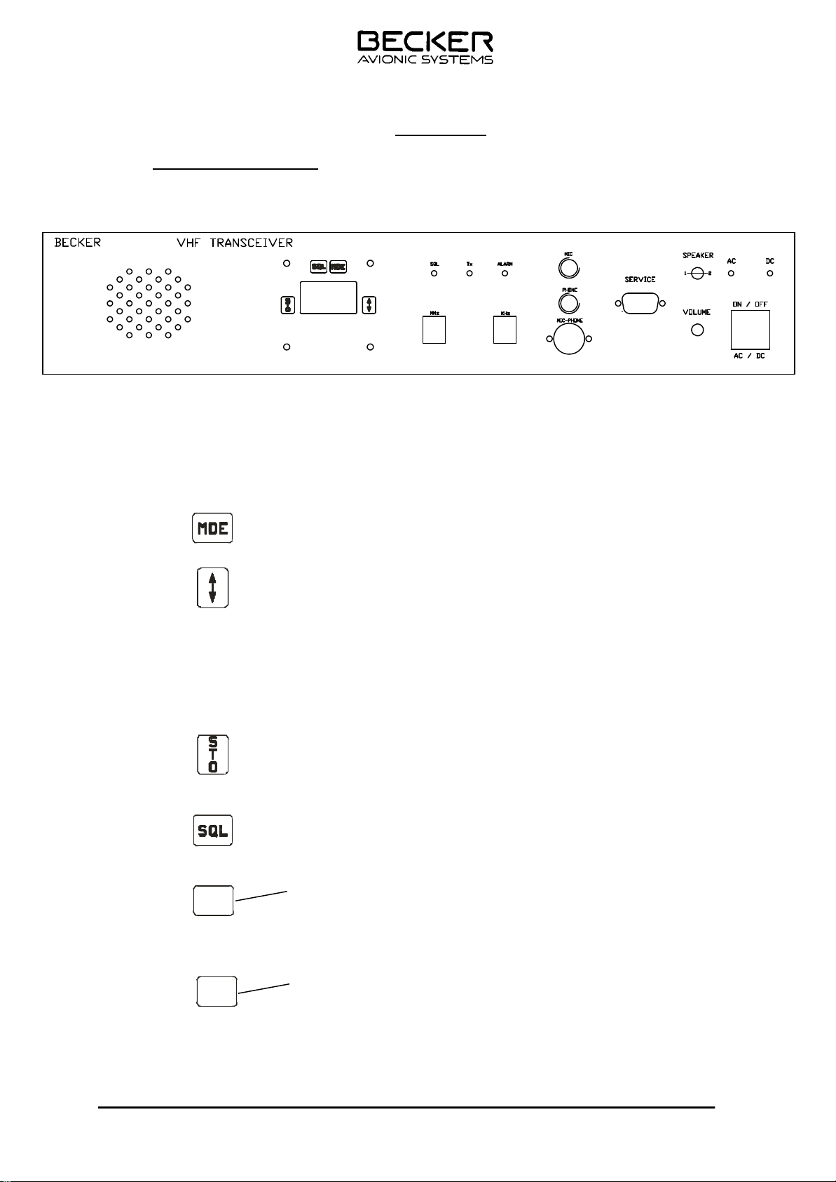
3.1 Controls and Indicators
Controls and indicators
1.
2. Mea ning of sym bols on con trols and in di ca tors
INSTALLATION AND OPERATION
TG480-(025)-(XX)
AR 4201 - ( )
OPERATION
A. C ontrols
MHz
Function key Selection of mode
Exchange key Mode 1:
Exchange of preset frequency
and active frequency.
Mode 3:
Switching between temperature
and operating voltage indication.
Store key Storage of set frequency or in
Mode 2 a change between the
channel selection mode and scan
mode.
Squelch key Switching the squelch on or off.
When the key is pressed, the
bottom line indicated ON or OFF
Frequency selector Switching the in di ca ted
f r e q u e n c y i n 1 M H z . ( l e v e r
switch) steps or the sto ra ge
channel upwards or downwards in
steps of 10.
KHz
TG480XX.01 Issue 04/07 3-1
Frequency selector Switches the indicated (lever
switch) frequency in 25 kHz
steps or the storage channel by
1 step in each case upwards or
downwards, without carry over.
Page 3 -1
Page 28
TG480-(025)-(XX)
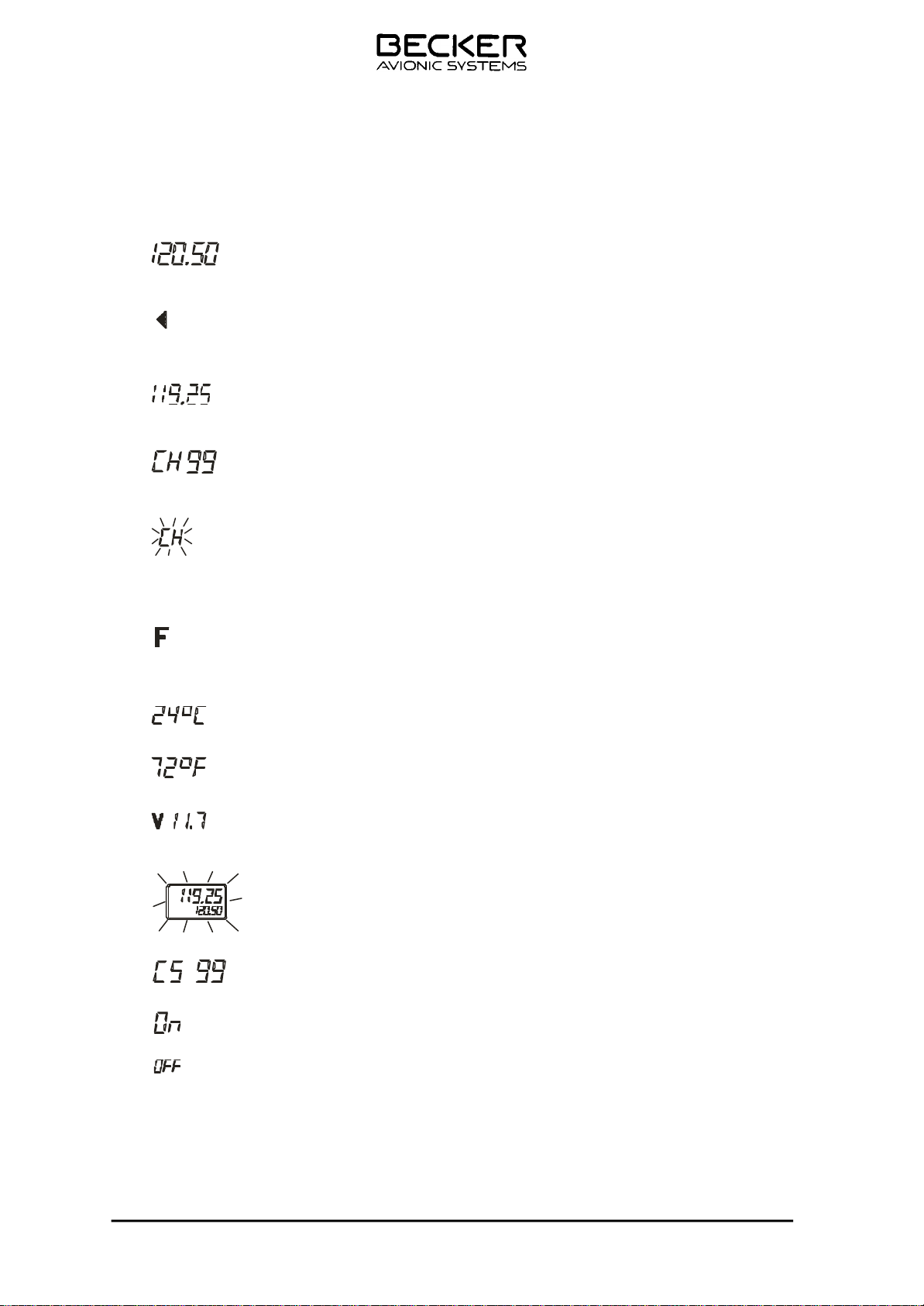
B. LCD (liquid crystal display) elements
(top line) Indication of active transmission/
(top line) Transmission indication (transmis-
(bottom line) Indication of preset transmission/
(bottom line) CH indication steady : in di ca tes
(bottom line) CH indication flashes :
reception frequency (active frequency).
sion button is pressed).
reception frequency (preset frequency).
the storage channel.
if the initiated storage operation is
not completed by pressing the
store key.
(bottom line) Indication that the selected stora-
ge channel is not occupied.
(bottom line) Indication of temperature in
°Celsius or
°Fahrenheit
Indication of supply voltage.
Indicating segment flashes.
Supply vol ta ge ≤ 10.5 V
(bottom line) Indication of scan function
(bottom line) Indication O N
(bottom line) Indication OFF
TG480XX.01 Issue 04/07 3-2
Page 29
TG480-(025)-(XX)
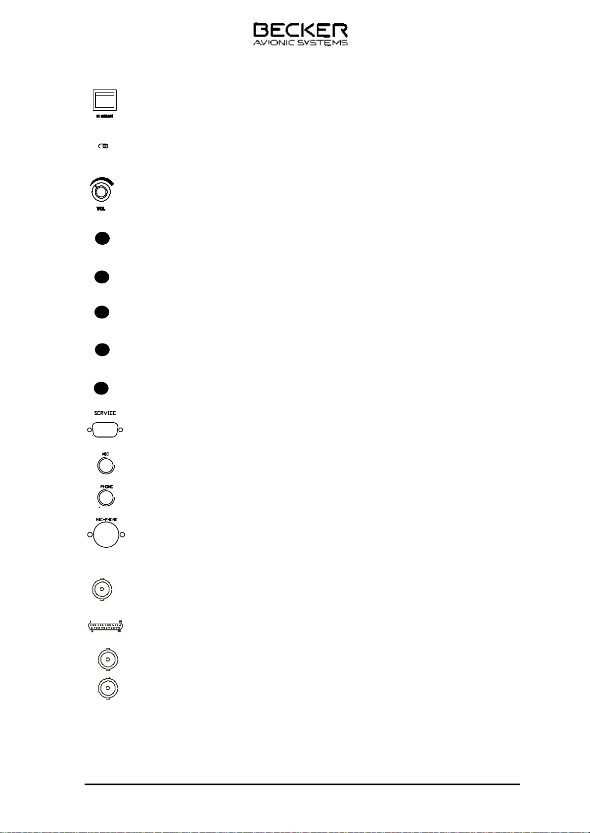
3.2 Meaning of symbols on controls and indicators
ON/standby switch Switching the ground station ON/OFF
Speaker
OI
Speaker switch
Switching the speaker ON/OFF
Volume control Adjustment of volume
Alarm LED Load mismatch > 2:1, Low power operation (red)
Tx Comes on during transmission (red)
SQL Comes on when there is an evaluatable reception signal (green)
Phone Headset socket
C. Rear of unit
AC Comes on when AC supply voltage is applied (yellow)
DC Comes on when the external DC supply voltage is applied (yellow)
Service Maintenance port
Mic Microphone socket, Head set
Mic/Phone Microphone / Headset socket
Mic Microphone socket, Head set
ANT 50 Ohm N female antenna connector
Phone Headset socket
Remote1 15-pin D subminiature
female
Programming and remote control options
Mic/Phone Microphone / Headset socket
Filter SMA female connectors. Filter IN & Filter OUT
RF SMA female connectors. Core RF OUT & PA RF IN
3.2.1 Over-voltage protection
There is an over-voltage protection function built-in. After over-voltage protection activates, a
minimum time lapse of 1 min. from the moment of switching off the input is required before any input
can turn on the supply again. Over-voltage protection setting is fixed at 115% - 135% nominal.
TG480XX.01 Issue 04/07 Page 3-3
Page 30
TG480-(025)-(XX)
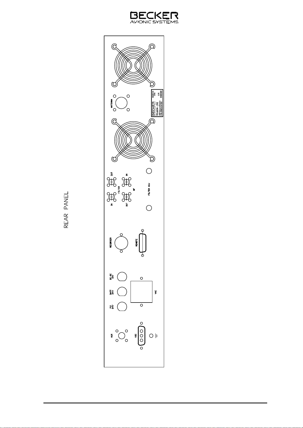
Ground terminal: Allows to connect the unit
with the ground
Fig. 3-2 Rear side
TG480XX.01 Issue 04/07 Page 3-4
Page 31

TG480-(025)-(XX)
3.3 Operating instructions
3.3.1 Switching on the VHF ground station
(1). Switch on the VHF ground station using the ON/OFF switch.
CAUTION
After the VHF ground station is switched off using the On/STBY switch it goes into
standby mode. All indicators go out except the AC or DC LED diode which continues
to remain on depending on the type of supply voltagey. To remove all current from the
VHF ground station requires the supply voltages to be switched off externally and the
fuse of the built in battery removed from the fuse holder. If a battery is installed in the
VHF Ground Station and the external supply voltages are disconnected and switch by
Ope ra ting in
mistake the ON/STANDBY switch in the ON position, the equipment is discharching the
internal battery
(2) The segments of the LC display will blink with the power supply voltage
having dropped down to 9V d.c. Following the blinking period the self-test
is conducted. With low supply voltage this test period can last up to 20
seconds. If the test is positive, the transceiver automatically switches to
the mode which was activated before switch-off.
If the test result negative, the LCD will display the first fault report for
approximately five seconds. If further faults were detected during test,
the corresponding fault reports will be displayed additionally. After is
playing the last fault report the equipment will switch automatically to the
operating mode which was activated before switch-off.
(3) The following fault signals are possible :
E 1 Processor defective
E 2 Synthesizer failed
E 3 Fault in EE-PROM
E 4 Controller (PIC) audio assembly defective
(4) The various modes are comprehensively described, toghether with the
setting of the equipment configuration in the service mode, in the Annex
to the General Operating Instructions.
B. T ransmit/ receive mode
(1) Set the frequency of the local ground station in the preset display and
press the exchange key. Rotate the VOL control to the centre position.
NOTE : If the error message E2 appears in the top line during ope-
ration, the synthesizer is not latching and further R/T
operations no longer possible. The VHF transceiver must
be check in the next service station
Page 3-5 TG480XX.01 Issue 04/07
Page 32

TG480-(025)-(XX)
(2) Operate the transmit button and call the ground station. Hold the micro-
phone close to the lips for optimum speech transmission.
NOTE : The arrow in the top line of the display indicates transmit
mode. During transmission a protective circuit prevents a
frequency change or frequency channel change even if the
frequency selector switch is rotated. The keying functions
on the control panel are also inhibited.
(3) Set the correct reception volume using the VOL control whilst the ground
station is answering.
(4) Switch on the squelch (press SQL key again). Weak reception
signals and reception noises are suppressed. The switch-on threshold of
the squelch can be set in the service mode.
NOTE : When changing the mode or the frequencies
(PRESET- ACTIVE frequency) the change is automatically
stored 2 second after the last change took place. Due to
this delay changes which were made immediately before
switching off the transceiver will not be memorized. Excepe-
tition: M e mory actions as storage by pressing the STO key.
C . Operation of intercom mode
(1) Switch on the IC switch (external).
(2) Operate the intercommunication (IC).
(3) If necessary, the IC volume can be adjusted to the noise level of the air-
craft (for adjustment refer to service mode).
D . Au dio au xi lia ry input
A second and third radio unit (navigation receiver) can be monitored simultane ously via the audio auxiliary input. During transmission the auxiliary input is
switched off from the audio end amplifier. If necessary, the input sensitivity
can be matched to the noise level of the aircraft (for setting refer to service
mode).
TG480XX.01 Issue 04/07 3-6
Page 33

TG480-(025)-(XX)
E. J amm ing of transmi t button
(1) The VHF- transceiver is fitted with a protective circuit to protect against
jamming of the transmit button or a short circuit on the key supply line.
For continuous transmissions exceeding two minutes the protective cir-
cuit automatically switches from transmission to reception. This avoids
the switched channel being blocked.
(2) It is possible to activate the transmitter again immediately by re-pressing
the transmit button. In the event of a fault, this is only possible after the
short circuit has been cleared or the transmit button released.
CAUTION : In Stock to be able to continue transmitting even with the
transmit button jammed, the VHF Transceiver must be
switched off and then back on again. After that the VHF
transceiver then continues to operate in the transmit mode
for a further two minutes.
F. Flas hing of the LCD
(1) If the power supply for the VHF transceiver drops below 10.5 V, the dis-
play begins to flash. This flashing indicates, when operating on batteries
for example, that the batteries require recharging. In practice the display
begins to flash in the transmit mode because this is when the power
consumption is greatest. If the power supply again increases abo ve
10.5 V, the flashing ceases.
(2) Because the discharge curves of the batteries are very dependant on the
type of battery, e.g. lead or nickel/cadmium accumulators, and the am
bienttemperature also influences the discharge curves, it is not pos si ble
to state precisely how long the VHF transceiver continues to be fully
functional after the LCD begins to flash.
(3) When transmitting, the batteries can be completely discharged after a
few transmission cycles but during reception functioning is still guaran-
teed in most cases for approximately 1 to 2 hours after the flashing begins. At 10 V supply voltage the unit still continues to function at
reduced transmission power.
G. Ope ra ti on of the va ri ous mo des
(1) The VHF transceiver performs various functions which are covered by
individual operating modes. The mode is selected by briefly pressing the
MDE key. If it is pressed for a long time (more than 1 second) this se lects mode 1.
TG480XX.01 Issue 04/07 3-7
Page 34
TG480-(025)-(XX)
(a) Modes:
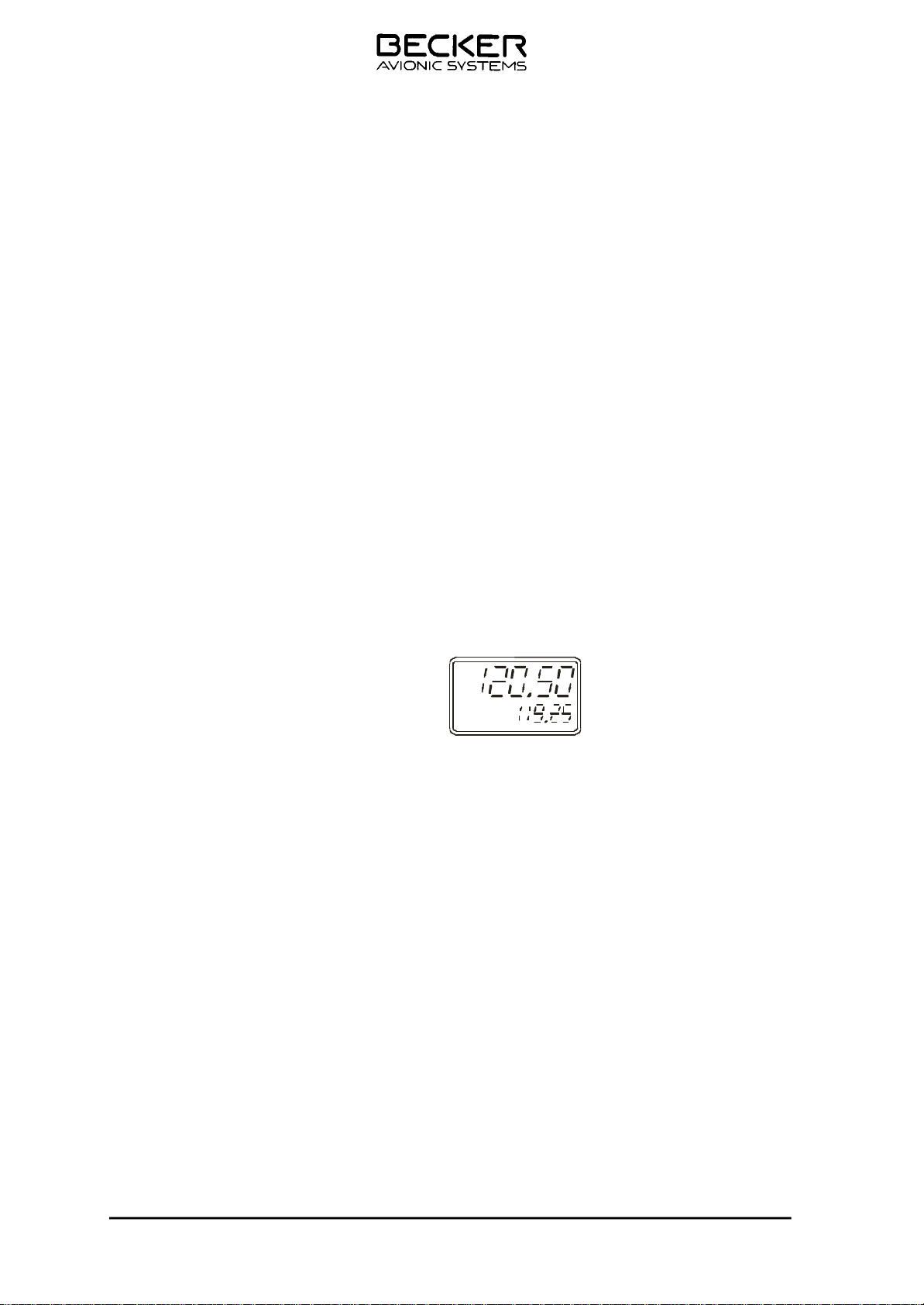
1 Standard mode (display of active and preset frequency),
setting the preset frequency and storing frequencies in the
storage channels.
2 Display of the storage frequencies in the storage channels or
calling up the scan function.
3 Display of temperature (option), power supply voltage and
active frequency
4 Service mode, for setting the equipment configuration.
NOTE : When changing the mode or the frequencies (PRE SET-
ACTIVEfrequency) the change is automatically stored 2
second after the last change took place. Due to this delay
changes whichwere made immediately before switching off
the transceiver will not be memorized. Exception: M e mory
actions as storage by pressing the STO key.
(2) Mode 1 (standard mode)
(a) The last displayed active and preset frequencies appear in the LCD
display.
(b) The preset frequency (bottom line) is set using the MHz and kHz
frequency selector switches.
(c) When the exchange key is pressed, a change from the active to the
preset frequency occurs. A further operation of the key cancels the
frequency change.
Storage operation
(d) Pressing the STO key.
The active frequency remains displayed in the top line.The
VHF transceiver is ready to transmit and receive on this frequency.
The preset frequency appears flashing in the bottom line.
The required frequency can be set using the kHz frequency selector
(steps of 1) or the MHz frequency selector (steps of 10).
Pressing the STO key.
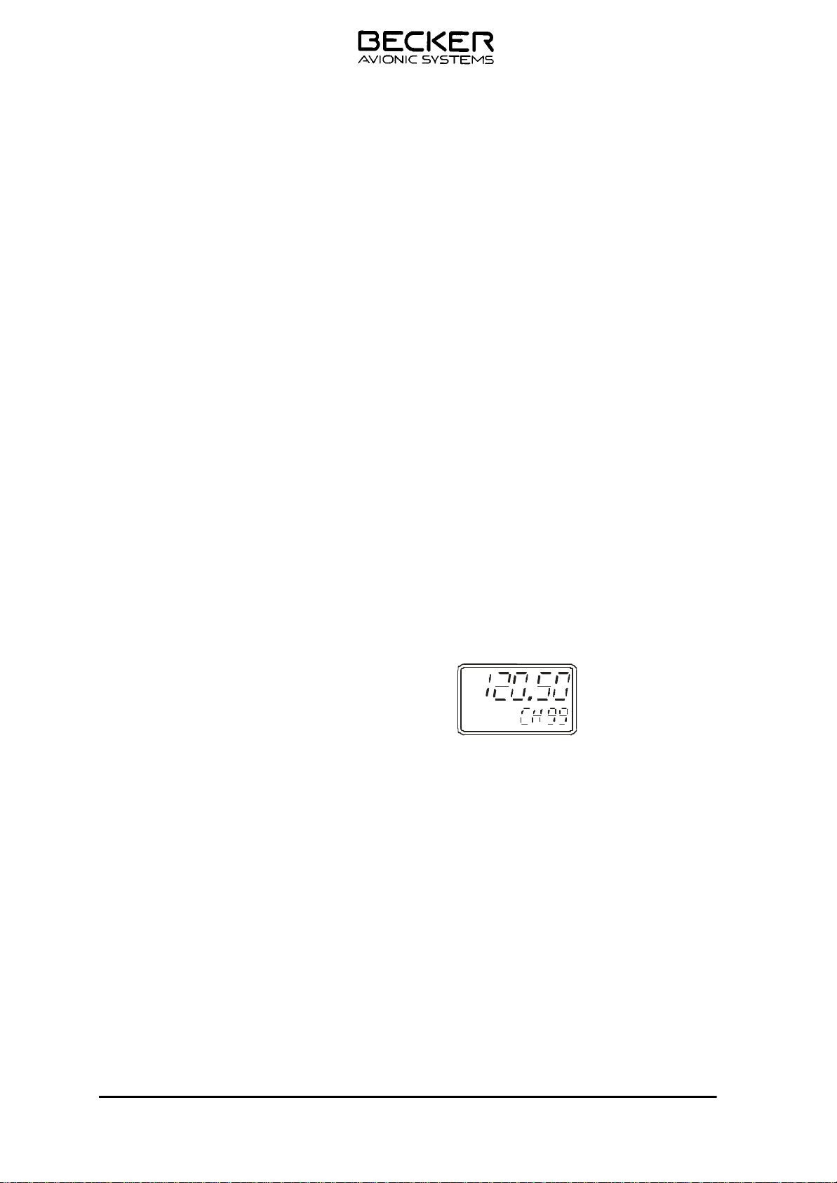
The next free channel is shown flashing “ch”. Press the STO key.
The selected frequency is stored in the free speaker channel and
the storage process is ended. A no memory channel is free, the
highest assign m e mory channel is selected automatically.
TG480XX.01 Issue 04/07 3-9
Page 35
TG480-(025)-(XX)
or
select the channel to be overwritten using the kHz frequency selector and
press the STO key. This means that this channel will be overwritten with
the new frequency and the storage process ended.
Note
If no input takes place within approximately seven seconds, t h e V H F
transceiver switches to the previously set mode.
Leaving the mode
To leave the mode, press the MDE key.
(3) Mode 2 (display of fixed frequencies in the various channels)
(a) Channel selection mode
NOTE : If in mode 2 the scan function is switched on in the ser-
vice mode, no storage operation can be activated in this
mode.
1 Select mode 2 using the MDE key. The last indicated storage
channel appears in the bottom line of the LCD and the stored
frequency is shown in the top line. The VHF transceiver is
ready to transmit and receive on this frequency.
2 Select required channel using the kHz frequency selector
(steps of 1) or the MHz frequency selector (steps of 10).
Free channel (no frequency stored) will be skipped when
selected.
3 If the Scan function is not activated, the storing function can
be initiated by pressing the STO-Key. Refer to description of
mode 1.
Note The top line indicates the active frequency. The ac ti ve
frequency indicated in the bottom line is flashing. S e lect
the desired frequency can be set using the kHz frequency selector or the MHz frequency selector.
4 Exit from mode 2 is achieved by pressing the MDE key.
TG480XX.01 Issue 04/07 3-10
Page 36

TG480-(025)-(XX)
(b) Scan function
Note: When operating the scan mode observe the regulations
for the aviation radio service
1 If the scan function is activated in the equipment configurati-
on, pressing the STO key changes from the channel selection
mode to the scan function. In the scan function, the frequency
appears in the top line of the display and the associated chan nel with the preset CS is shown in the bottom line.
2 In the scan function, either all the occupied storage channels
or a required range of storage channels can be scanned. The
scanning range is specified in the service mode. The various
storage channels are scanned in 200 ms intervals. If the microprocessor finds a carrier in one of the channels, it holds a
short on this channel and checks whether an eva lua tab le
signal is present. If no evaluatable signal is present, it swit ches to the next channel and then reverts to the 400 ms intervals (milliseconds range). In the event of an evaluatable reception signal being received the VHF transceiver remains on
the storage channel until an evaluatable reception signal is no
longer present.After a hold time 0 to 60 seconds (can be set
in the service mode) the scanning of the storage channels a t
200 ms intervals begins again. The set squelch level is the
criterium for an evaluatable reception signal, regardless of
whether the squelch is activated or not.
3 The VHF transceiver is equipped with channel priority. This
function can be switched ON or OFF in service mode SF 18
NOTE: If an adequate signal is required on the priority chann e l
with option channel priority switched ON, the VHF transcei-
ver automatically leaves the SCAN mode and is ready for
transmission and receive on this channel. For return to the
SCAN mode, again press the STO key.
4 The scan function is terminated by pressing the STO key. The
VHF transceiver then begins to operate again in the channel
selection mode - the CS in the bottom line goes out and CH
appears. Exit from mode 2 is accomplished in the same way
as described in the channel selection mode.
TG480XX.01 Issue 04/07 3-12
Page 37
TG480-(025)-(XX)
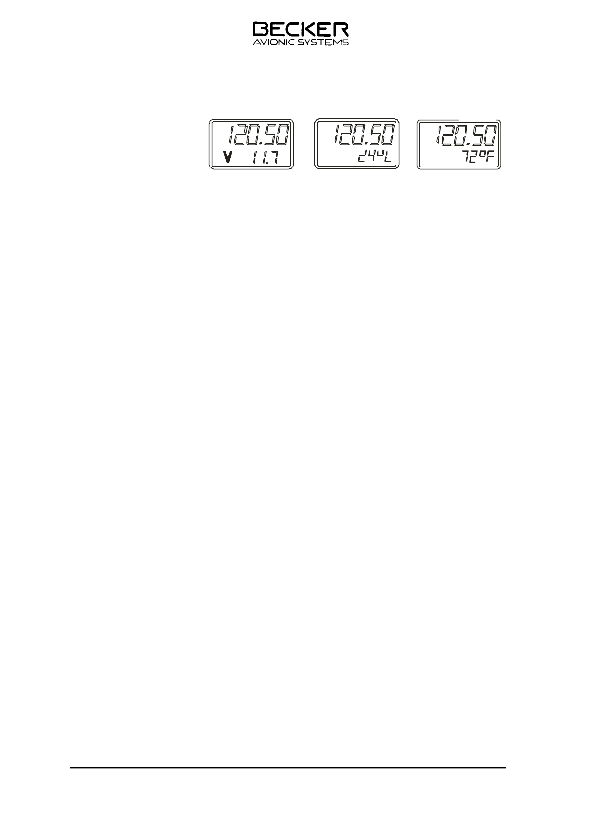
(4) Mode 3 Indication of supply voltage or temperature (option)
When the exchange key is pressed, a change from the supply vol ta ge and temperature indication occurs.
NOTE : If no temperature sensor is connected, this mode is skip-
ped when the exchange key is pressed.
(a) The supply voltage and temperature is continuously measured.
Indication occurs only in mode 3. The mode is selected by briefly
pressing the MDE key once or several times (corresponding to the
previous state) the active frequency on which the VHF transceiver
is ready for operation is shown in the top line and the mea su red
voltage/temperature is displayed in the bottom line. The display
in °C or °F can be set in the service mode.
(b) The active frequency (top line) can be changed using both frequen-
cy selector switches. A storage operation is activated using the
STO key. This procedure is described in mode 1.
(c) To exit mode 3 it is necessary to press the MDE key.
TG480XX.01 Issue 04/07 3-13
Page 38

TG480-(025)-(XX)
(5) Service mode (equipment configurations)
The service mode is meant to enable the ground technicians to set the
equipment configuration and must not be used in flight.
(a) The following settings can be changed or set:
S q L Setting the switch-on threshold of the squelch
SIdE Setting the sidetone volume
a U Setting the audio auxiliary volume
I C Setting the IC volume
SF5 Calibrating the temperature sensor
SF6 Setting the addressable storage locations
SF7 Setting the temperature display in °C or °F
SF8 Switching on the scan functio n
SF9 Setting the hold time after completion of a call in the
scan mode
S F 1 0 Release the frequency setting (channel selection only)
S F 1 1 Release the frequency stor a g e
S F 1 2 Erasure of stored frequencies
S F 1 3 Setting the “channel start” of the scanning range
S F 1 4 Setting the “channel end” of the scanning range
COdE Entering a password to interlock the equipment
configuration.
S F 1 6 Dynamic mike input sensitivity
S F 1 7 Inhibiting the transmit mode for one or more memory
channel
S F 1 8 Channel priority ON/OFF switch (option)
F S q L No function
S F 2 0 Speaker muting switch ON/OFF
S F 2 1 Increase the audio power output
- . - Indication the software version and change status
NOTE : The equipment configuration SqL, SIdE, AU, IC and
SF16 settings given in the service mode are set by the
factory as basic settings using standard values. If rever-
sion to the standard values is required, the portable VHF
Transceiver must be switched off and switched on again
simultaneously pressing the STO and MDE keys. This
does not overwrite the password.
If no temperature sensor is connected, the mode SF5
and SF 7 is skipped when the mode key is pressed.
If the SF8 scan function is not activated, than the func-
tion SF9, SF13 and SF14 will not be displayed.
The settings SF 17 and SF 18 are optionen. When the
optionen are not activated, the mode SF17 and
SF 18 is skipped when the mode key is pressed.
TG480XX.01 Issue 04/07 3-14
Page 39

TG480-(025)-(XX)
(b) Calling up the service mode
Switch off the VHF transceiver. Hold the mode key (MDE)
pressed and at the same time switch on the unit. The VHF
transceiver switches to the service mode without a unit test.
SqL appears in the top line and the switch on threshold of
the squelch is shown on the bottom line.
NOTES :
l The set tings are se lec ted in steps by brief ly pres sing the MDE key
in the ser vi ce mode. If the MDE key is pres sed at the end of the set ting, the set ting SqL then ap pe ars. If a di rect re turn to the SqL set ting is re qui red the MDE key must be pres sed for at least one se cond.
l If set tings are not ac ti vat ed, (e.g. scan functi on) this mode is skip -
ped by pressing the mode key.
l In the ser vi ce mode the VHF trans cei ver ope ra tes in de pen dent ly of
the set tings on the con trol pa nel, on the fre quen cy which was last
set as the ac ti ve fre quen cy. Wenn the PTT-Key is pressed in the
service mode, the dis play in di ca tes in the top line the ac ti ve fre quency
l The user can interlock his equipment configuration settings with
the aid of a pass word. The VHF trans cei ver is de li ver ed from the
fac to ry wit hout a pass word. Sec ti on COdE “En try of pass word for
in ter loc king the equip ment con fi gu ra ti on” des cri bes how to en ter a
password.
1 Setting the squelch threshold
a If function SqL is called up, the following displays appear.
Top line SqL
Bottom line 00 to 200 Standard value 130
(HI se n sitivi t y LO)
b By means of the kHz switch, the squelch threshold can be
altered upwards or downwards in steps of 5. The set value is stored by pressing the STO key.
TG480XX.01 Issue 04/07 3-15
Page 40

TG480-(025)-(XX)
2 Setting the sidetone lev e l
a Call up the SIdE function using the MDE key. The follo-
wing displays appear.
Top line SIdE
Bottom line 00 to 63 Standard v a lue 32
(LO level HI)
b Using the kHz switch, The sidetone level can be altered
upwards or downwards. The set value is stored by pres-
sing the STO key.
Upwarts serial No.: 1500 Press the PTT key and set the
correct sidetone volume using the kHz switch. The side-
tone level can be altered upwards or downwards. The set
value is stored by pressing the STO key.
3 Setting the audio auxiliary level
a Call up the AU function using the MDE key. The follo-
wing displays appear.
Top line A U
Bottom line 00 to 63 Standard v a lue 63
(LO level HI)
b Using the kHz switch, alter the audio auxiliary level up-
wards or downwards. The set value is stored by pressing
the STO key.
4 Setting the IC lev e l
a Call up the IC function using the MDE key. The foll o -
wing displays appear :
Top line I C
Bottom line 00 to 63 Standard v a lue 32
(LO level HI)
b The IC level can be changed upwards or downwards
using the kHz switch. The set value is stored by pressing
the STO key.
TG480XX.01 Issue 04/07 3-16
Page 41

TG480-(025)-(XX)
5 Calibrating the temperature sensor
a If no temperature sensor is connected, this mode is skip-
ped when the mode key is pressed.
b Calibration is only necessary if the sensor has been retro -
spectively fitted or replaced.
c After calling up using the MDE key, the following display
appears.
Top line SF 5
Bottom line Measured temperature
d Measure the ambient air temperatur of the sensor by me -
ans of a suitable thermometer and set temperatur display
on the LCD. To this measured value by mean of the kHz
frequency selector. The entry is stored by pressing the
STO key and of the temperature sensor is calibrated .
6 Setting addressable storage locations 1 to 99.
a Call up the function using the MDE key. The following
display then appears.
Top line SF 6
Bottom line 1 to 99
b The number of the storage channel between 1 to 99 can
be selected as required using the kHz switch and stored
by pressing the STO key. If the number of storage chan-
nels is limited and if channels outside the limited a r e a
have already been used, these can no longer be call e d
up. The data in the channels outside the area continues
to remain stored and it can be re-used at any time by
lifting the restricted area.
7 Setting the temperature display in the °C or °F.
a If no temperature sensor is connected, this mode is skip-
ped when the mode key is pressed.
b Call up function SF 7 using the MDE key. The following
displays appear :
Top line SF 7
Bottom line °C of °F
c The required display is selected using the kHz switch and
the selection is stored by pressing the STO key.
TG480XX.01 Issue 04/07 3-17
Page 42

TG480-(025)-(XX)
8 Switching on the scan function
a If the SF8 scan function is not activated, than the function
SF9, SF13 and SF14 will not be displayed.
b Call up function SF 8 using the MDE key. The following
display appears.
Top line S F 8
Bottom line OFF or On
c Select the required function using the kHz switch and
store the selection by pressing the STO key.
OFF = scan function off
On = scan function on
9 Setting the hold time in the scan function (only displayed, if
SF8 is activated).
a Call up function SF 9 using MDE key. The following dis -
plays appear :
Top line S F 9
Bottom line 0 .0 to 60.0
b The hold time can be set as required between 0,0 ..0,9
seconds using the kHz seletor switch and between 0..60
seconds using the MHz selector switch. The set value is
stored by pressing the STO key.
1 0 Inhibiting the frequency setting (channel selection only).
a Call up function SF 10 using the MDE key. The following
displays appear :
Top line SF 10
Bottom line OFF or On
b Select the required function using the kHz key and stor e
the function by pressing the STO key.
OFF= Frequency setting not possible. The VHF transceiver can only work on the frequencies stored in the individual channels.
On = Frequency setting possible (standard setting).
TG480XX.01 Issue 04/07 3-18
Page 43

TG480-(025)-(XX)
11 Inhibiting the frequency storage
a Call up function SF 11 using the MDE key. The following
display appears.
Top line S F 1 1
Bottom line OFF or On
b Select the required function using the kHz switch and
store the selection by pressing the STO key.
OFF = The storage of frequencies in the individual chan-
nels is not possibl e . T h e VHF transceiv e r ca n onl y
work on the set frequency.
On = Storage of frequencies in the individual channels
is possible (standard setting)
12 Erase stored frequencies
a Call up function SF 12 using the MDE key. The following
display appears.
Top line S F 1 2
Bottom line CH channel number
b Select the channel to be erased using the kHz (steps of
1) or MHz (steps of 10) switch. The stored frequency is
erased by pressing the STO key.
13 Setting the “channel start” scanning range (only displayed, if
SF8 is activated).
a Call up function SF 13 using the MDE key. The following
displays appear :
Top line S F 1 3
Bottom line CS channel number
b Select the starting channel, using the kHz (steps of 1) or
MHz (steps of 10) switch, at which the scan function is to
begin. The starting channel is stored by pressing the STO
key.
Note
When this function is set OFF, the active and preset fre quencies which were set last remains are available in
Mode 1
TG480XX.01 Issue 04/07 3-19
Page 44

TG480-(025)-(XX)
1 4 Setting the “channel end” scanning range.(only displayed, if
SF8 is activated).
a Call up function SF 14 using the MDE key. The following
displays appear :
Top line SF 14
Bottom line CS channel number
b Using the kHz (steps of 1) or MHz (steps of 10) switch,
select the end channel at which the scan function is to
stop. Store the end channel by pressing the STO key.
1 5 Entry of password to interlock the equipment configuration.
a Call up the COdE function using the MDE key. The foll o -
wing display appears.
Top line COdE 15
Bottom line 0
b Set any 4-digit numerical code using the kHz (steps of 1)
or MHz (steps of 10) switch. Store the numerical code by
pressing the STO key.
NOTE : As soon as a password is given an 0 appears
in the bottom line when the service mode is
called up. The numerical code must then be
input using the MHz or kHz switch. If the VHF
transceiver detects a false numerical code, it
automatically switches to the last mode.
If the password is to be erased or changed,
this is done by calling up the service mode
using the old password. The COdE functio n
is then chosen and either an 0 is entered
everywhere or the changed numerical code
is entered.
1 6 Setting the dynamic mike input sensitivity
a Call up function SF 16 using the MDE key. The following
displays appears :
Top line SF 16
Bottom line 00 bis 63 Standard v a lue 32
(LO sensitivity HI)
b The dynamic mike input sensitivity can be changed
upwards or down-wards using the kHz switch. The set
value is stored by pressing the STO key.
TG480XX.01 Issue 04/07 3-20
Page 45

TG480-(025)-(XX)
17 Inhibiting the transmit mode for one or more memory chann e l
(option)
a Call up function SF 17 using the MDE key. The following
displays appears :
Top line S F 1 7
Bottom line CS channel number
b Using the kHz (steps of 1) or MHz (steps of 10) switch,
select the desired channel for inhibiting the transmit
mode. Store the channel by pressing the STO key. Seve-
ral channels can be selected on priority channels. The let
ter T appears in the bottom line before CS. When the
STO key is pressed again, the inhibiting transmit mode is
canceled. The letter T is not appears in the bottom line
before CS.
18 Channel priority ON/OFF switch (Option)
a Call up function SF 18 using the MDE key. The following
displays appears :
Top line S F 1 8
Bottom line CS channel number
b Using the kHz (steps of 1) or MHz (steps of 10) switch,
select the desired channel. Store the channel by pres -
sing the STO key. Several channels can be selected on
priority channels.
19 FSqL no function
20 Speaker muting switch ON/OFF
a Call up function using the MDE key. The following
displays appears :
Top line SF20
Bottom line OFF or On
OFF = Speaker m u ting on
On = Speaker always switched on
b Select the function using the kHz switch. Store t h e
required function by pressing the STO key. This selection
becomes active after ending the service mode.
TG480XX.01 Issue 04/07 3-21
Page 46

TG480-(025)-(XX)
2 1 Increase the audio power output
a Call up function using the MDE key. The following
displays appears :
Top line S F 2 1
Bottom line OFF or On
OFF = Standard audio power output
On = maximum audio power output
b Select the function using the kHz switch. Store the
required function by pressing the STO key. This selection
is active immediately by pressing the STO key.
2 2 Indication the software spec. no.: and change status
a Call up function using the MDE key. The following
displays appear.
Top line software spec. no.: and chang e
status Microprocessor
Bottom line software spec. no.: and change status
CO-Miroprocessor (PIC)
2 3 Basic settings in the service mode
The volume settings given in the service mode are set by the
factory as basic settings using standard values. If reversion to
the standard values is required, the VHF transceiver must be
switched off and switched on again by simultaneously pres sing
the STO and MDE keys.
2 4 Ending of the service mode
The VHF transceiver must be switched off to end the service
mode.
TG480XX.01 Issue 04/07 3-22
Page 47

TG480-(025)-(XX)
4. Safety instructions
The following instructions must be followed for safe operation of the VHF transcei ver:
A. S witch off the unit wh en star ting or shut ting down en gi ne s.
B. A speec h test i s to be performed b e fo re start up and it should be no ted that if
the speech test is carried out clo se to the ground sta ti on the re sults may be
positive even if the antenna cable is broken or short-circuited. At a distance
of 5 to 10 km no connection will be made.
C. Use a loud voi c e for spee ch com mu ni ca ti on and h old the mi c ro pho ne clo se to
the lips. Ot her wi se ca bin noise can be intrusive and make understanding difficult.
D. Use only mi cro pho nes or he ad sets which are suit ab le for use in air craft. In air-
craft made of wood or syn the tic ma te ri als or in gli ders or he li cop ters, in co ming
radiation on the equip ment an ten na can af fect the in te gra ted am pli fier of the
mi cro pho ne (feed back). This is noticeable in the ground station by whist ling
and/or heavy distortion. The described disturbances can occur in different ways
on the different transmission channels.
E. T ran smit button s can stick a nd ca u s e c on t i n u o us t ran smission. Therefore, when
transmitting ensure that the arrow in the top line on the left next to the active
fre quen cy dis play dis ap pe ars when the trans mis si on but ton is re lea sed.
TG480XX.01 Issue 04/07 3-23
Page 48

TG480-(025)-(XX)
Blank
TG480XX.01 Issue 04/07 3-24
Page 49

TG480-(025)-(XX)
3.4 Safety instructions
The following instructions must be followed for safe operation of the VHF station:
l A speech test is to be performed before startup and it should be noted that if the
speech test is carried out close to the ground station the results may be positive
even if the antenna cable is broken or short-circuited. At a distance of 5 to 10 km
no connection will be made.
l Use a loud voice for speech communication and hold the microphone close to the
lips. Otherwise cabin noise can be intrusive and make understanding difficult.
l Use only microphones or headsets which are suitable for use in aircraft. Incoming
radiation on the equipment antenna can affect the integrated amplifier of the
microphone (feedback). This is noticeable in the ground station by whistling and/or
heavy distortion. The described disturbances can occur in different ways on the
different transmission channels.
l Transmit buttons can stick and cause continuous transmission. Therefore, when
transmitting ensure that the LED display (red) disappears when the transmission
button is released.
Warning
l High voltages inside refer servicing to qualified personal
l Disconnect power inout before servicing
Page 3-25 TG480XX.01 Issue 04/07
Page 50
BECKER AVIONICS, INC.
QUALITY SYSTEM FORM
TEST REPORT: TG480-(20)
FINAL INSPECTION / TEST
TG480-(20) VHF Transceiver
*PART NUMBER: 0940.436-926 SERIAL NUMBER: __________
1. TRANSMITTER TEST
TX. Carrier Power (Without Modulation):
VSWR 1:1 VSWR 2:1 Freq. Offset
Requirements: 20 +/- 5W < 1200 Hz
118.000 MHz _________ W _________ W __________ Hz
127.500 MHz _________ W _________ W __________ Hz
136.975 MHz _________ W _________ W __________ Hz
Modulation and Distortion:
*Dynamic Mike (
VSWR 1:1 VSWR 2:1
Mod.% Dist.% Mod.% Dist.%
Requirements: 85 +/-5 % < 5% 85 +/-10% < 10%
118.000 MHz ______ ______ ______ ______
127.500 MHz _____ ______ ______ ______
136.975 MHz ______ ______ ______ ______
Over modulation: ________ (none) ________ (none)
*Standard Remote Mike
VSWR 1:1 VSWR 2:1
Mod.% Dist.% Mod.% Dist.%
Requirements: 85 +/-5 % < 5% 85 +/-10% < 10%
118.000 MHz ______ ______ ______ ______
127.500 MHz _____ ______ ______ ______
136.975 MHz ______ ______ ______ ______
Over modulation: ________ (none) ________ (none)
Min. Requirements Max. Measurements
1 kHz / 10mV audio input)
(1 kHz / 775mV audio input)
Modulation AF Response:
*(127.5 MHz, 775mV, 1 kHz)
fmod.= 100 Hz 20 ______ dB
350 Hz 6 ______ dB
500 Hz ______ dB
1000 Hz 0 ___0__ dB
*TG480-20 S/N _________ QF-154 Rev.0 01/18/08
Page 1 of 5
Page 51
BECKER AVIONICS, INC.
QUALITY SYSTEM FORM
TEST REPORT: TG480-(20)
2500 Hz 6 ______ dB
4000 Hz 20 ______ dB
Transmitter Compressor:
*(10mV - 30 mV, 1kHz) dif. fmod.= 5 _______ %
*(775mV – 1V, 1kHz) dif. fmod.= 5 _______ %
Automatic Shutdown: 2 minutes _______ min
Tx Alarm: OK _______
2. RECEIVER TEST
Sensitivity (SINAD)
(1000 Hz, 30% mod., AF Level = 775mV, 3uV EMF)
118.000 MHz 12dB ________dB
127.500 MHz 12dB ________dB
136.975 MHz 12dB ________dB
SQL Sensitivity: (Squelch opens at): *5uV ________uV
AGC Characteristic:
(127.5 MHz, 1000 Hz/30%, AF Level=775mV)
(5 uV – 100 mV EMF) 3dB ______dB
Bandwidth:
(127.500 MHz / 1uV EMF / 400Hz / 80% / 0 dB AF output)
(Increase RF output by 6dB)
Higher frequencies 8 ______kHz
Lower Frequencies 8 ______kHz
Min. Requirements Max. Measurements
Selectivity:
(127.500 MHz / 1uV EMF / 400Hz / 80% / 0 dB AF output)
127.475 MHz 60 ______dB
127.525 MHz 60 ______dB
(127.500 MHz / 1uV EMF / 400Hz / 80% / 0 dB AF output)
(Increase RF output by 40dB)
Higher frequencies 17 ______kHz
*TG480-20 S/N _________ QF-154 Rev.0 01/18/08
Page 2 of 5
Page 52

BECKER AVIONICS, INC.
QUALITY SYSTEM FORM
TEST REPORT: TG480-(20)
Lower frequencies 17 ______kHz
Audio Output Power and Distortion factor:
(127.500 MHz / 100 uV / 1000 Hz / 85%)
AF at 600 Ohms >
7 ______V
Distortion @ 7V: 10 ______%
Audio Reponse:
(127.5 MHz / 100uV / 1000Hz / 30%)
350 Hz -6 ______dB
1000 Hz 0
dB
2500 Hz -6 ______dB
4000 Hz 18 ______dB
3. CONTROL PANEL TEST
Display: (all digits flashing) OK ________
MDE Key: OK ________
Freq. Selection: 1MHz OK ________
1KHz OK ________
Exchange Key: OK ________
Service Mode:
- SF1 Setting the switch to ON
Threshold of the squelch OK ________
- SF2 Cal. The temp. sensors OK ________
- SF3 Setting the addressable storage location OK ________
- SF4 Setting temperature display OK ________
- SF5 Switching on the scan function OK ________
- SF6 Setting the hold timer after
completion of a call in the scan mode OK ________
- SF7 Inhibiting the freq. setting
(Channel selection only) OK ________
- SF8 Inhibiting the frequency storage OK ________
- SF9 Erasure of stored frequencies OK ________
- SF10 Setting the “channel start” of
*TG480-20 S/N _________ QF-154 Rev.0 01/18/08
Page 3 of 5
Page 53

BECKER AVIONICS, INC.
QUALITY SYSTEM FORM
TEST REPORT: TG480-(20)
the scanning mode OK ________
- SF11 Setting the “channel end” of the
scanning mode OK ________
-SF12 Entering a password to interlock
the equipment configuration OK ________
-SF13 Set Sensitivity for Dynamic Mike OK ________
-SF14 Inhibit Tx for Memory-Channels OK ________
-SF15 Set Channel Priority ON/OFF OK ________
-SF16 Set Squelch Fast Mode OK ________
Panel illumination: OK ________
AC/DC Switchover OK ________
4. ACCESORY FUNCTIONS
a. 15 VDC (500mA) 12 16 ________
b. RS 232 OK ________
c. PTT (Gnd-Active) OK ________
d. COR (Low-Active) OK ________
e. Tx Audio
(%Mod, 0dB/775mV) 70 95 ________
Over modulation: none ________
f. Rx Audio (dB) -9 0 1 ________
g. Recorder Output
Tx Audio (dB) -9 0 1 ________
Rx Audio (dB) -9 0 1 ________
*TG480-20 S/N _________ QF-154 Rev.0 01/18/08
Page 4 of 5
Page 54
BECKER AVIONICS, INC.
QUALITY SYSTEM FORM
TEST REPORT: TG480-(20)
Remarks:
AR4201 S/N: ____________
RF Power Amplifier S/N: ______________
Reflectometer S/N: ______________
Bandpass Filer S/N: _______________
SINGLE CHANNEL OPTION
Frequency: ___________ MHz
Internal band pass filter Yes:______ No:______
The TG480-20 has been tested successfully and is ready for operation.
Test Equipment Used:
DESCRIPTION SERIAL NUMBER
MARCONI RADIO TEST 132628/032
TEKTRONIX 485 OSCILLOSCOPE B144152
BIRD 4431 WATTMETER 8849
DCR-25B DC POWER SUPPLY 1256
Tested by: ___________________ Title: _________________ Date:___________
Inspected by: _________________ Title: ________________ Date:___________
BECKER AVIONICS, INC. 10376 USA Today Way Phone: 954-450-3137
Miramar, FL 33025 Fax : 954-450-3206
*TG480-20 S/N _________ QF-154 Rev.0 01/18/08
Page 5 of 5
Page 55
BECKER AVIONICS, INC.
QUALITY SYSTEM FORM
TEST REPORT: TG480-(50)
FINAL INSPECTION / TEST
TG480-(50) VHF Transceiver
*PART NUMBER: 0940.435-926 SERIAL NUMBER: __________
1. TRANSMITTER TEST
TX. Carrier Power (Without Modulation):
VSWR 1:1 VSWR 2:1 Freq. Offset
Requirements: 50 +/- 5 W < 1200 Hz
118.000 MHz _________ W _________ W __________ Hz
127.500 MHz _________ W _________ W __________ Hz
136.975 MHz _________ W _________ W __________ Hz
Modulation and Distortion:
*Dynamic Mike (
VSWR 1:1 VSWR 2:1
Mod.% Dist.% Mod.% Dist.%
Requirements: 85 +/-5 % < 5% 85 +/-10% < 10%
118.000 MHz ______ ______ ______ ______
127.500 MHz _____ ______ ______ ______
136.975 MHz ______ ______ ______ ______
Over modulation: ________ (none) ________ (none)
*Standard Mike
1 kHz / 10mV audio input)
(1 kHz / 775mV audio input)
VSWR 1:1 VSWR 2:1
Mod.% Dist.% Mod.% Dist.%
Requirements: 85 +/-5 % < 5% 85 +/-10% < 10%
118.000 MHz ______ ______ ______ ______
127.500 MHz _____ ______ ______ ______
136.975 MHz ______ ______ ______ ______
Over modulation: ________ (none) ________ (none)
Min. Requirements Max. Measurements
Modulation AF Response:
*(127.5 MHz, 775mV, 1 kHz)
fmod.= 100 Hz 20 ______ dB
350 Hz 6 ______ dB
500 Hz ______ dB
1000 Hz 0 ___0__ dB
*TG480-50 S/N ____________ QF-155 Rev. 0 01/18/08
Page 1 of 5
Page 56
BECKER AVIONICS, INC.
QUALITY SYSTEM FORM
TEST REPORT: TG480-(50)
2500 Hz 6 ______ dB
4000 Hz 20 ______ dB
Transmitter Compressor:
*(10mV - 30 mV, 1kHz) dif. fmod.= 5 _______ %
*(775mV – 1V, 1kHz) dif. fmod.= 5 _______ %
Automatic Shutdown: 2 minutes _______ min
Tx Alarm: OK _______
2. RECEIVER TEST
Sensitivity (SINAD)
(1000 Hz, 30% mod., AF Level = 775mV, 3uV EMF)
118.000 MHz 12dB ________dB
127.500 MHz 12dB ________dB
136.975 MHz 12dB ________dB
SQL Sensitivity: (Squelch opens at): *5uV ________uV
AGC Characteristic:
(127.5 MHz, 1000 Hz/30%, AF Level=775mV)
(5uV – 100 mV EMF) 3dB ______dB
Bandwidth:
(127.500 MHz / 1uV EMF / 400Hz / 80% / 0 dB AF output)
(Increase RF output by 6dB)
Higher frequencies 8 ______kHz
Lower Frequencies 8 ______kHz
Min. Requirements Max. Measurements
Selectivity:
(127.500 MHz / 1uV EMF / 400Hz / 80% / 0 dB AF output)
127.475 MHz 60 ______dB
127.525 MHz 60 ______dB
(127.500 MHz / 1uV EMF / 400Hz / 80% / 0 dB AF output)
(Increase RF output by 40dB)
*TG480-50 S/N ____________ QF-155 Rev. 0 01/18/08
Page 2 of 5
Page 57

BECKER AVIONICS, INC.
QUALITY SYSTEM FORM
TEST REPORT: TG480-(50)
Higher frequencies 17 ______kHz
Lower frequencies 17 ______kHz
Audio Output Power and Distortion factor:
(127.500 MHz / 100 uV / 1000 Hz / 85%)
AF at 600 Ohms >
7 ______V
Distortion @ 7V: 10 ______%
Audio Reponse:
(127.5 MHz / 100uV / 1000Hz / 30%)
350 Hz -6 ______dB
1000 Hz 0
dB
2500 Hz -6 ______dB
4000 Hz 18 ______dB
3. CONTROL PANEL TEST
Display: (all digits flashing) OK ________
MDE Key: OK ________
Freq. Selection: 1MHz OK ________
1KHz OK ________
Exchange Key: OK ________
Service Mode:
- SF1 Setting the switch to ON
Threshold of the squelch OK ________
- SF2 Cal. The temp. sensors OK ________
- SF3 Setting the addressable storage location OK ________
- SF4 Setting temperature display OK ________
- SF5 Switching on the scan function OK ________
- SF6 Setting the hold timer after
completion of a call in the scan mode OK ________
- SF7 Inhibiting the freq. setting
(Channel selection only) OK ________
- SF8 Inhibiting the frequency storage OK ________
*TG480-50 S/N ____________ QF-155 Rev. 0 01/18/08
Page 3 of 5
Page 58

BECKER AVIONICS, INC.
QUALITY SYSTEM FORM
TEST REPORT: TG480-(50)
- SF9 Erasure of stored frequencies OK ________
- SF10 Setting the “channel start” of
the scanning mode OK ________
- SF11 Setting the “channel end” of the
scanning mode OK ________
-SF12 Entering a password to interlock
the equipment configuration OK ________
-SF13 Set Sensitivity for Dynamic Mike OK ________
-SF14 Inhibit Tx for Memory-Channels OK ________
-SF15 Set Channel Priority ON/OFF OK ________
-SF16 Set Squelch Fast Mode OK ________
Panel illumination: OK ________
AC/DC Switchover OK ________
4. ACCESORY FUNCTIONS
a. 15 VDC (500mA) 12 16 ________
b. RS 232 OK ________
c. PTT (Gnd-Active) OK ________
d. COR (Low-Active) OK ________
e. Tx Audio
(%Mod, 0dB/775mV) 70 95 ________
Over modulation: none ________
f. Rx Audio (dB) -9 0 1 ________
g. Recorder Output
Tx Audio (dB) -9 0 1 ________
Rx Audio (dB) -9 0 1 ________
*TG480-50 S/N ____________ QF-155 Rev. 0 01/18/08
Page 4 of 5
Page 59
BECKER AVIONICS, INC.
QUALITY SYSTEM FORM
TEST REPORT: TG480-(50)
Remarks:
AR4201 S/N: ____________
RF Power Amplifier S/N: ______________
Reflectometer S/N: ______________
Bandpass Filer S/N: _______________
SINGLE CHANNEL OPTION
Frequency: ___________ MHz
Internal band pass filter Yes:______ No:______
The TG480-50 has been tested successfully and is ready for operation.
Test Equipment Used:
DESCRIPTION SERIAL NUMBER
MARCONI RADIO TEST 132628/032
TEKTRONIX 485 OSCILLOSCOPE B144152
BIRD 4431 WATTMETER 8849
DCR-25B DC POWER SUPPLY 1256
Tested by: ___________________ Title: _________________ Date:___________
Inspected by: _________________ Title: ________________ Date:___________
BECKER AVIONICS, INC. 10376 USA Today Way Phone: 954-450-3137
Miramar, FL 33025 Fax : 954-450-3206
*TG480-50 S/N ____________ QF-155 Rev. 0 01/18/08
Page 5 of 5
 Loading...