

Page 1
HCBT-800
High Capacity
Seed Treater
Installation and
Operation Manual
Page 2

This page intentionally left blank
Page 3

3.0
Table of Contents
The following HCBT manual contains
installation, operation, parts list and
technical drawing information.
Please read and understand these
instructions completely before proceeding to
install and operate the equipment.
Bayer CropScience reserves the right to
change specications, models, components,
or materials at any time without notice.
For further detailed information, contact the
Bayer CropScience technical representative
for your area.
Please have this operation manual available
General categories
4.0 - Introduction
5.0 - Installation
8.0 - HCBT Drum Operation
10.0 - Seed Calibration
12.0 - CBP Tank Installation
14.0 - CBP Tank Calibration
17.0 - Treating Operation
21.0 - Maintenance
22.0 - Guidlines for Treating
23.0 - Slurry Preparation
when contacting Bayer CropScience.
Contact Information:
Bayer CropScience
4895 12th Avenue East
Shakopee, MN 55379
(800)634-6738
FAX: (952)445-8282
www.bayercropscienceus.com
HCBT© 2008 Gustafson Equipment RF M/013008/HCBT/579KB
24.0 - Calculations
26.0 - Liquid Product Worksheet
27.0 - Powder Woksheet
28.0 - Guidelines for Successful Treating
30.0 - Limited Warranty
Page 4

4.0
Introduction
Gustafson’s HCBT-800 continuous ow treater is designed for treating many crops including
soybeans, wheat, rice and peas. Operators can treat from a seed holding bin or from bulk
seed bags.
USE CAUTION!
Always use caution and common sense
when working with any chemical.
Read the product label and MSDS
carefully and follow their
instructions exactly as described.
Page 5
5.0
Installation
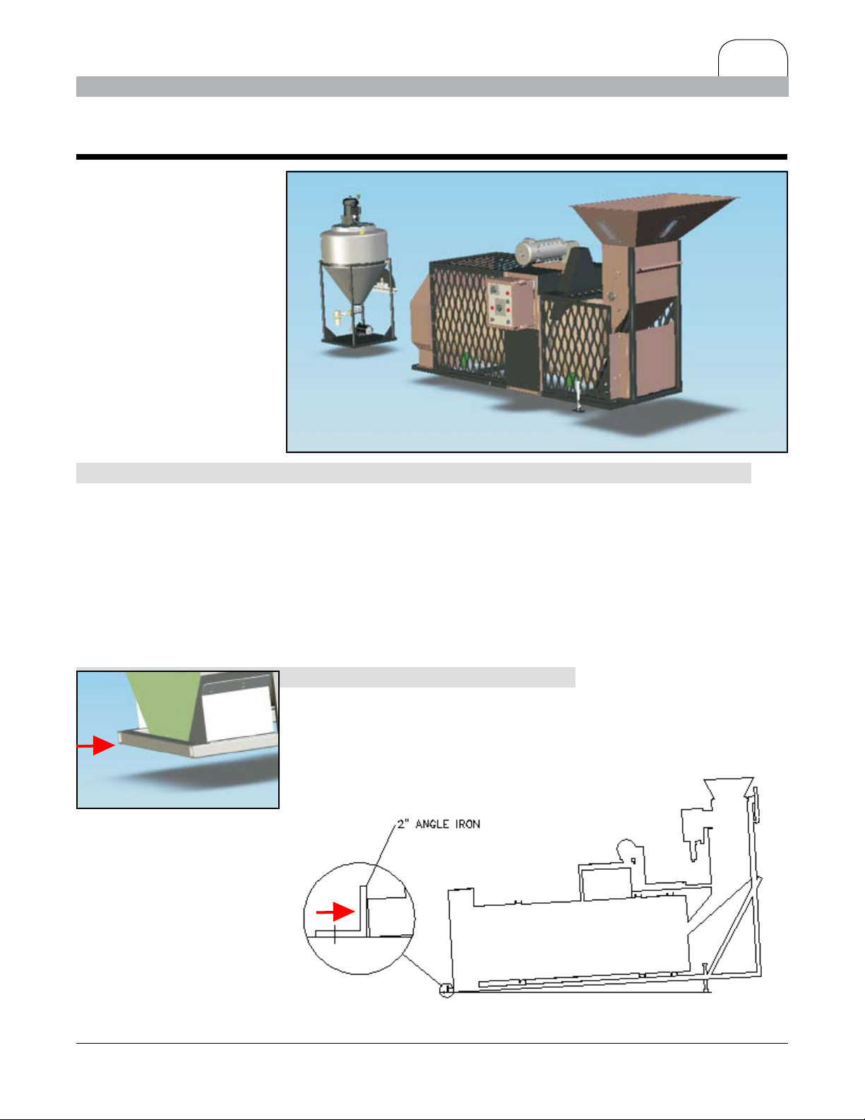
Treater Discharge End
1. Provide a mounting surface which is a oor or frame
strong enough to support the HCBT and the weight of the
seeds you will process at any one time. Consider also the
weight of any conveying system for input and discharge as
well as the weight of containers at both ends of the process.
Your input feed and output collector should be of equal
capacity.
2. Secure to the mounting surface
a 2” X 32” angle iron directly in front of the frame on
the discharge end of the HCBT. The angle iron is used to
keep the HCBT from moving forward while allowing the
angle of the machine to be changed for various
capacities and crops.
Continued...
Page 6
6.0
Intstallation (continued)
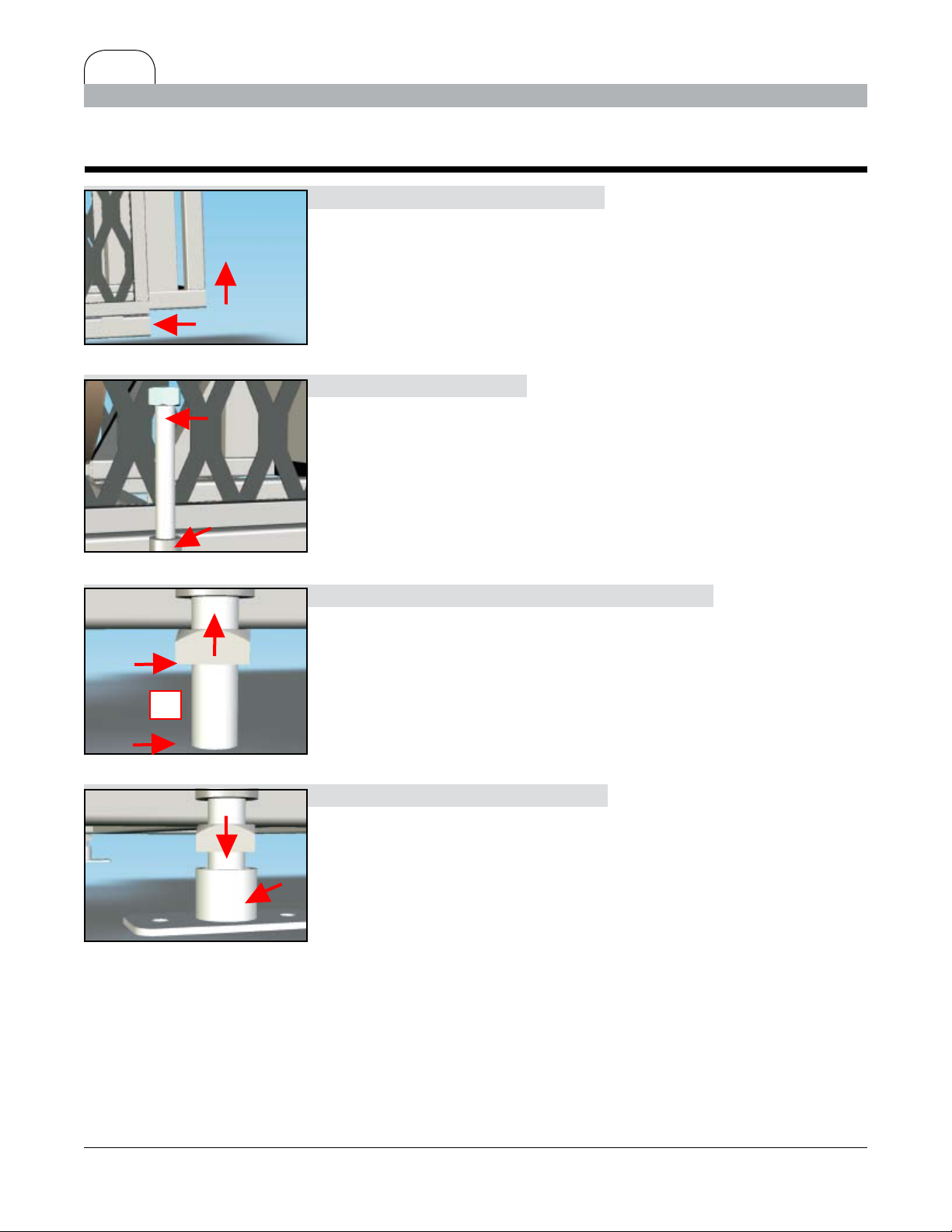
3. Use a chain hoist or jack
to lift the Inlet End of the HCBT approximately 6”.
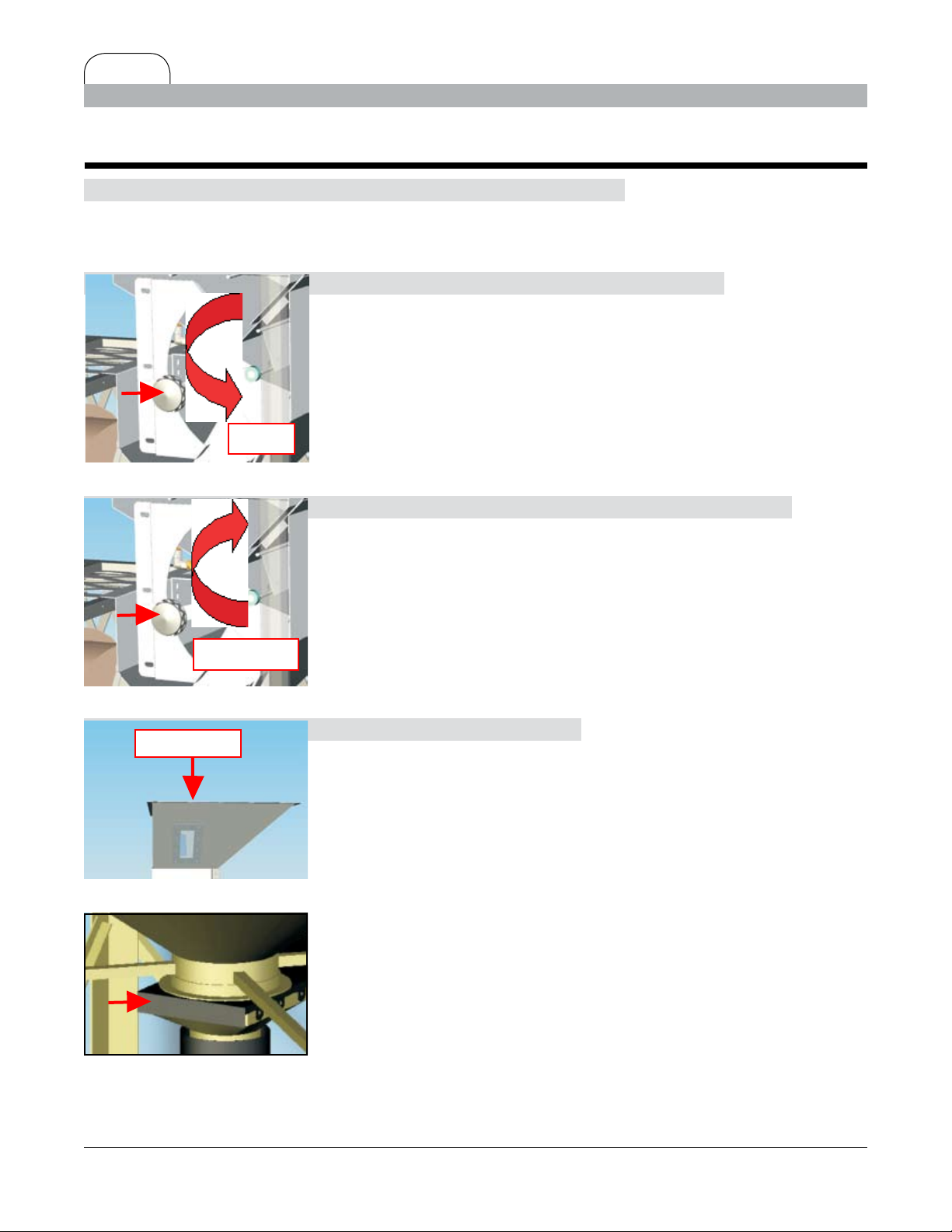
Treater Inlet End
4. Insert the Lift Rod
into the frame hole with the head of the bolt positioned up.
Treater Inlet End
4”
Adjuster Nut
Lift Support
5. Thread the ¾” – 10 SQ Adjuster Nut
from the bottom of the bolt up to allow approximately 4” of
space from the bottom of Adjuster Nut to the lower end of
the bolt.
6. Position the Lift Support
below each bolt. Lower the HCBT to allow some weight to
be on the Lift Support. Position the Lift Support parallel to
the treater frame. Completely lower the HCBT onto the Lift
Support. Bolt or weld the Lift Support to the oor.
Page 7
Inlet Hopper
7.0
Intstallation (continued)
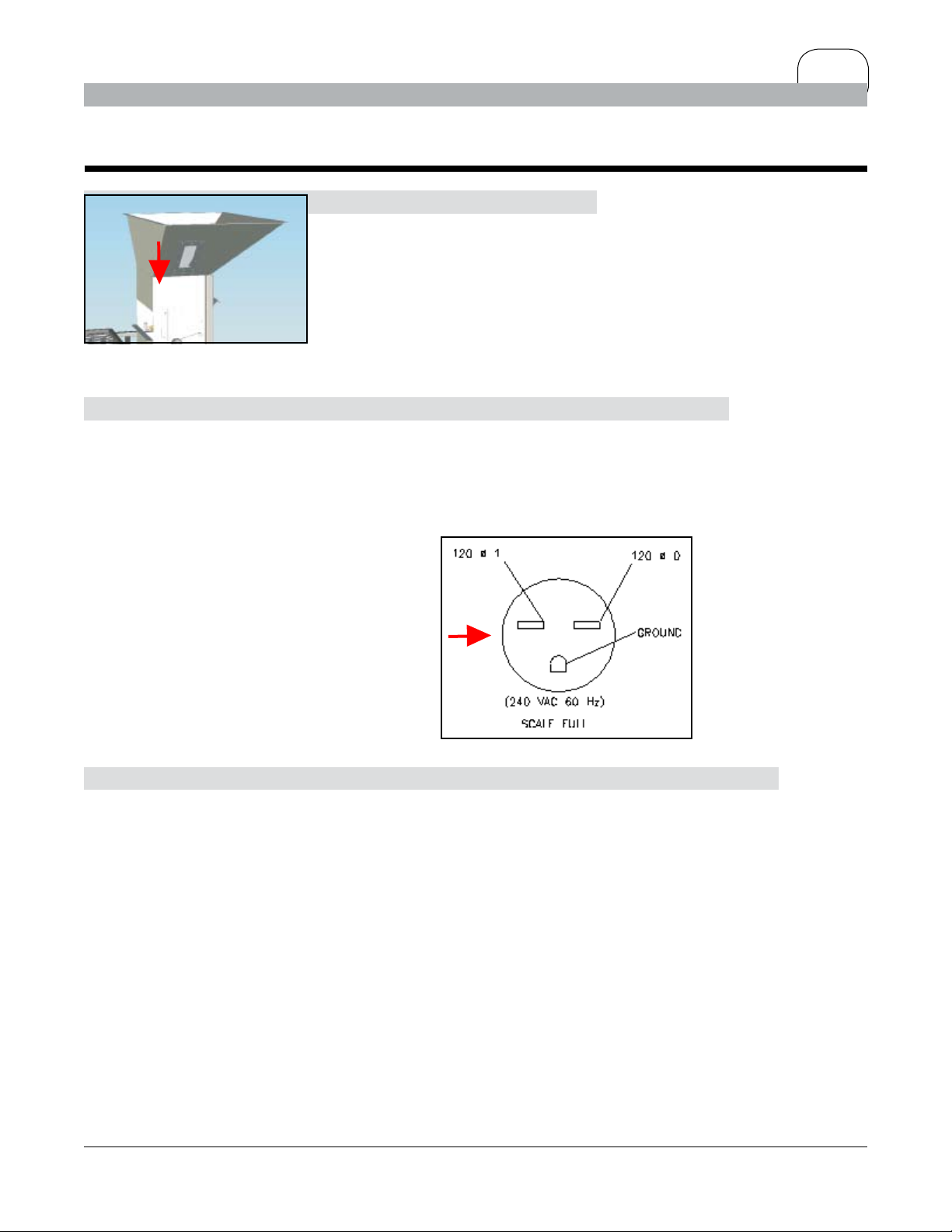
7. Place the Inlet Hopper
on the treater and bolt in place.
8. Once the treater is permanently mounted
have the machine wired by a qualied electrician.
The treater requires 220 VAC / 60 HZ, 19amps, single phase.
The treater has a male plug directly wired to the control
box. The female end of the plug should be wired as shown.
9.
Ensure that your delivery and discharge system
can handle the product ow you select.
E
stimated capacities for the treater:
Soybeans = 800 pounds per minute
Wheat = 400 pounds per minute
Rice = 400 pounds per minute
Page 8
8.0
HCBT Drum Operation
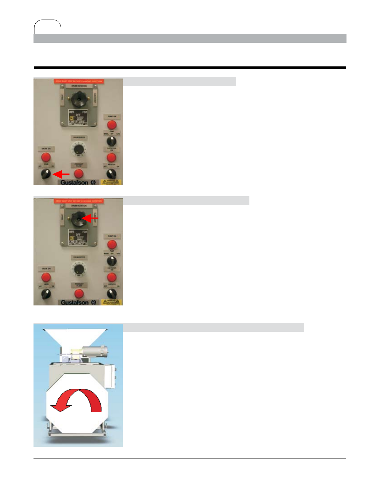
1. Turn the Control Box Panel
drum switch to ON.
Control Box panel
2. Turn the drum rotation switch
Control Box panel
to F (TREAT).
Note: When facing the discharge end of the drum,
it should be rotating counter clockwise. If the drum is
running clockwise turn the drum switch OFF,
disconnect the power source and rewire the female plug,
reversing the 120vAC supply wires (refer to stp 8 on page
Drum Rotation
7.0).
Continued...
Page 9
9.0
HCBT Drum Operation (continued)
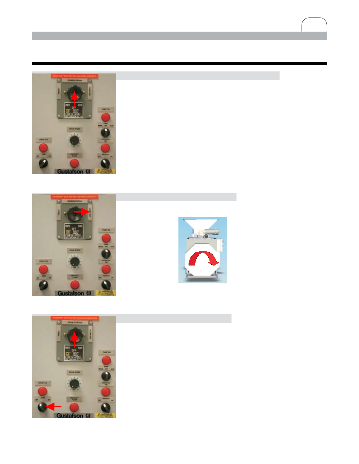
3. Once the drum is running counterclockwise
turn the drum rotation switch to OFF.
Control Box panel
Control Box panel
4. Turn the Drum Rotation Switch
to
R (CLEAN OUT). The drum should be running clockwise.
Drum Rotation
5. Turn the Drum Switch to OFF,
then the Drum Rotation switch to the OFF position.
Testing the HCBT is complete.
Control Box panel
Page 10
10.0
Seed Calibration
Determine the feed rate of seed.
You will need a watch or stopwatch, scale, calibrated
beaker and a collection bin for the Calibration process.
1. Close the HCBT Hopper Flow Door Handle.
CLOSED
Hopper Flow Door handle
2. Then open the HCBT Hopper Flow Control Handle
OPEN 1-3/4”
Hopper Flow Door handle
SEED SOURCE
HCBT Inlet Hopper
about 1-3/4”.
3. Position your Seed Source
(i.e. bulk bag, conveyer with holding bin, holding bin, etc.
with an OPEN/CLOSE seed gate) above the HCBT Inlet
Hopper.
Seed Source needs to have an
OPEN/CLOSE Seed Gate to control
the seed ow to the HCBT Inlet
Hopper
Continued...
Page 11

Seed Calibration (continued)
4. Have a collection bin ready
to catch seed from the HCBT Hopper Housing. Open the
HCBT hopper ow door (Pull UP on the lip and then let it
DOWN). Use the OPEN/CLOSE seed gate on the seed source
bin above the HCBT inlet hopper to start the seed ow.
Open Hopper Flow Door
5. Time the seed ow for one minute.
Close the OPEN/CLOSE seed gate on the seed source bin.
11.0
SEED
Seed Flow
DOWN TO REDUCE
Hopper Flow Door handle
UP TO INCREASE
Then close the HCBT hopper ow door.
6. Weigh the seed that has gone through in one minute.
Write down your time and calculate the output per minute.
Use the following example with your choice of weight per
minute in place of the 600 pounds.
Example: 600 pounds discharge in one minute.
If 600 pounds is an acceptable capacity, leave the hopper
ow door in the position you have set.
If the capacity is too
hopper ow door and calibrate again.
high then reduce the opening on the
Hopper Flow Door handle
If the capacity is too low then increase the opening of the
hopper ow door and calibrate again.
Repeat steps
capacity.
4-6 until you achieve your required feed
Page 12

12.0
CBP Tank Installation
1. Mount the Metering Ball Valve Assembly
to the CBP-30 Tank stand with the supplied U-Bolts.
Tighten to secure the mounting to the tank stand.
Metering Ball Valve Mounting
CBP-30 Tank
3/8” OD Tubing To Treater
1/2” OD Tubing From Pump
CBP-30 Tank Metering Ball Valve
2. Connect 1/2” OD tubing on CBP-30 Tank Chemical Pump
port to the bottom Port of the metering ball valve. Connect
3/8” OD tubing from the CBP-30 Tank metering ball valve top
port to the elbow tting under the HCBT inlet hopper.
3/8” OD Tubing to Elbow Fitting
1/2” OD Pump to Ball Valve
Continued...
Page 13

13.0
CBP Tank Installation (continued)
7. Fill the CBP-30 Tank with Liquid Seed Treatment Product
through the Tank Lid.
NOTE: Read and understand the liquid seed treatment
product label and material safety data sheet (MSDS).
Follow all instructions for use, handling, precautions,
protective equipment and other instructions listed on the
Tank Lid
label and the MSDS.
8. Plug in the CBP-30 Tank Agitation motor
110v power cord to the 110v female connector on the HCBT
Control Panel.
CBP-30 Tank Power Cord
HOLD
9. Turn the HCBT AGITATOR Switch
to the ON position (light will go ON).
10. Turn the PUMP Switch
to MANUAL and HOLD (light will go on) to deliver treatment
product to the treater. This jog switch will reset to OFF
when released.
Installation is complete, you are now ready to test the Pump.
HCBT Pump Control Switches
Page 14

900
46 50 54 59 63 68 72 76 81
850
45 49 53 58 62 66 70 74 78
800
45 49 52 56 60 64 68 72 76
750
44 48 52 55 59 62 66 70 73
700
44 47 51 54 57 61 64 68 71
650
43 46 50 53 56 59 62 65 69
600
43 46 49 52 54 57 60 63 66
550
42 45 48 50 53 56 58 61 64
500
42 44 47 49 52 54 56 59 61
450
41 43 46 48 50 52 54 57 59
400
41 43 45 47 49 51 52 54 56
350
40 42 44 45 47 49 51 52 54
300
40 41 43 44 46 47 49 50 52
250
39 41 42 43 44 45 47 48 49
200
39 40 41 42 43 44 45 46 47
2 3 4 5 6 7 8 9 10
APPLICATION RATE (OZ/CWT)
SEED FLOW (LBS/MIN)
14.0
CBP Tank Calibration
Metering Ball Valve Setting
CBP-30 Tank Metering Ball Valve
Example (refer to chart at bottom of page):
Your seed output (from page 11.0) is 600 pounds per minute.
Assume you are using a product that can be applied, ready to
use, at a rate of 6 ounces per 100 pounds of seed. Look at the
bottom of the chart and nd 6 ounces. Follow the numbers up
the chart to the point where it intersects with 600 pounds per
minute.
At 6 ounces per 100 pounds of seed:
600 pounds per minute = 54.
These valve settings are approximate and are a guide to use as
a starting point.
Continued...
Page 15

CBP Tank Calibration (continued)
1/2” OD Chemical Pump Port
15.0
Adjust the Liquid Flow:
1. Disconnect the liquid treatment tubing
from the elbow tting under the HCBT inlet hopper and
place it in a calibrated beaker to measure the liquid
seed treatment output.
2. Turn the HCBT Pump AGITATION switch
to ON.
HCBT AGITATOR Control Switch
HOLD
HCBT Pump Control Switch
3. Hold the HCBT Pump switch
to MANUAL. Measure the treatment output after one
minute. Release the Pump switch to turn the pump
OFF. Record your volume measurement. Pour the
liquid seed treatment back into the premix tank.
4. If you do not get the desired volume in one minute,
change the valve setting up or down and repeat step 3
above. Repeat this process until the output of the
liquid seed treatment product is correct. When you
liquid output per minute is correct, the calibration
CBP-30 Tank Metering Ball Valve
process is complete.
Continued...
Page 16

16.0
Calibration (continued)
5. Connect the liquid treatment tubing
to the elbow tting under the HCBT inlet hopper.
1/2” OD Chemical Pump Port
6. Hold the HCBT Pump switch
in MANUAL to deliver treatment product to the treater.
This jog switch will reset to OFF when released.
HOLD
HCBT Pump Control Switch
The system is calibrated. Treating may begin.
Page 17

17.0
Treating Operation
WARNING: Do not leave the machine unattended while treating seed. The HCBT
is NOT an automatic machine!
Using the settings for seed feed rate (page 11.0) and liquid ow adjustment (page 15.0):
1. Turn the Control Box Panel
drum switch to ON.
Control Box panel
Control Box panel
2. Turn the drum rotation switch
to F (TREAT).
3. Turn the HCBT Pump AGITATION switch
to ON.
HCBT AGITATOR Control Switch
Continued...
Page 18

18.0
Treating Operation (continued)
4. Turn the pump switch to AUTO.
The pump uses the Proximity Sensors inside the inlet hopper
to indicate when liquid treatment dispersion to the treater
should begin and will stop the pump as soon as the seed level
in the seed hopper is lower than the proximity sensor.
The Product Flow Light below the Drum Speed Dial will turn
on to indicate that seed is owing past the sensors.
Pump Control Switch
Drum Speed Dial
Product Flow Light
5. Fine tune the drum rotation
by increasing or decreasing the Drum Speed Dial to get the
best possible coverage and the maximum volume.
WARNING:
Never stop the drum full of seed, unless it is an
emergency.
Staring the drum when it is full of seed can cause overloads
that may stress electrical components. Clean out as much
seed as possible BEFORE restarting the drum.
Continued...
Page 19

19.0
Treating Operation (continued)
1. When seed ow stops, turn off the Pump.
The Product Flow Light below the Drum Speed Dial will turn
off when seed has stopped owing past the sensors.
Pump Control Switch
Control Panel
Product Flow Light
2. When a few seeds remain in the drum,
turn the control box Drum Switch to
OFF.
Continued...
Page 20

20.0
Treating Operation (continued)
3. When drum rotation stops,
Control Box panel
turn the Drum Rotation Switch to
the Drum Switch to ON and run the drum until it is empty.
5. Turn the Drum Switch to OFF,
then the Drum Rotation switch to the OFF position.
Wait for the drum to stop, then switch the drum rotation to
F (TREAT) for the next treating job.
Before treating other crops or varieties,
R (CLEAN OUT) and turn
Control Box panel
ensure all switches are set to the
entire seed system and treater. Be sure it is clean to avoid
contamination of other seed sources.
If the HCBT will not be used for a while,
any liquid treatment you intend to continue using and that
you have diluted with water may settle in the CBP tank, so
continue to operate the agitator.
If the machine will not be used for a long time,
drain the premix tank (refer to page 21.0, maintenance).
OFF position. Inspect the
Page 21

1/2” OD Chemical Pump Port
21.0
Maintenance
1. Disconnect the liquid treatment tubing
from the elbow tting under the HCBT inlet hopper and
place it in a secondary container.
2. Hold the HCBT Pump switch
to MANUAL and Completely empty the CBP-30 Tank.
This jog switch will reset to OFF when released.
HOLD
HCBT Pump Control Switch
Tank Lid
3. Fill the CBP-30 Tank with clean water
mixed with ammonia or a mild detergent or a cleaning solution
recommended by the manufacturer of the treatment product.
Repeat step 2 to ush the entire system.
If the applicator is going to be stored in subfreezing tempera-
tures, ush with alcohol to prevent freezing which will cause
pump damage. Save all rinse water and use for next treatment
or dispose of properly by following the MSDS sheet. If a more
thorough cleaning is necessary, the metered pump kit is easily
disassembled and reassembled.
For winter storage, disconnect and drain all hoses to ensure
that no components will freeze and cause damage. Clean the
drum and seed chamber and spray with light food grade oil
to help prevent corrosion. Store the treating unit indoors to
extend the life and appearance of the unit.
NOTE: Failure to clean your treater properly, or failure to completely drain all liquid from the pump and lines after use, may
damage the equipment and void any warranties expressed or
implied. It will not damage the pump to run it dry or with the
valves in the closed position.
Page 22

22.0
Guidelines for Treating
Follow these guidelines for a more successful operation.
1. Avoid spouting seeds at an angle into the treater. A surge hopper installed above the
treater is recommended.
2. To shut off seed ow, use the slide gate on the treater or on the holding bin.
3. Treat only clean seed. Remove dust at the holding bins and at the treater inlet.
4. Keep the weighpan tripping quickly to achieve a constant ow of seed and liquid seed
treatment into the coating chamber.
5. Keep the liquid seed treatment tank lid closed during operation to keep out foreign
objects.
6. In all hose lines, avoid dips and valleys where liquid may settle and not drain after
treating. Keep your hoses as close to vertical as possible.
7. Protect supply hoses and bypass return hoses from abrasion, sunlight and being dislodged
with PVC pipe or a similar material.
8. Adjustment to the liquid seed treatment ow should be made with the bypass adjust
ment valve located at the pump. Do not place valves, lters or anything that may restrict
liquid ow at any point on the treatment supply hose.
9. When using a premix tank, be sure the bypass return hoses reach down into the liquid
treatment. Do not cut them too short. If the hose is above the liquid level in the premix
tank it can cause excessive foaming.
10. Use tap water at normal temperatures when mixing owables. Do not use hot water.
-
Page 23

Slurry Preparation
This is the recommended sequence for adding products to produce your slurry.
1. Start with approximately 2/3 to 3/4 of the total water volume.
2. Add dyes and/or colorants.
3. Add water soluble products, such as Orthene or Ag-Strep.
4. Add wettable powders, such as Guacho 75 ST or Lorsban 50 SL.
5. Add any water-dispersible granular products.
6. Add water based owables.
7. Add emulsiable concentrates or concentrated emulsion products.
8. Add oil based owables, such as DiPel ®4L.
23.0
9. Polymeric and/or coatings additives are added last (special rules may apply).
10. Use the water balance for container rinsing.
Note:
The 8 & 8 Rule says 8 ounces of powder will displace 8 uid
ounces of water.
Page 24

24.0
Calculations
KEY
1. To convert rate per CWT to rate-per-bushel: multiply the rate per CWT by . (decimal
point) bushel weight. Example: 4 oz per CWT on wheat = 2.4 OZ/BU 4 x .60 = 2.4
2. To convert rate per bushel to rate per CWT: divide rate per bushel by . (decimal point)
bushel weight. Example: 2.4 OZ per bushel on wheat - 4 OZ per CWT 2.4 x .60 = 4 OZ
per CWT
3. To calculate part per million (PPM):
OZ AI/CWT
.0016 = PPM
4. To calculate OZ AI/CWT from PPM:
PPM x .0016 = OZ AI/CWT
5. To calculate OZ AI/FL OZ (owable or liquid):
Pounds AI/Gallon x 16
128 = OZ AI/CWT
6. To calculate OZ AI/CWT: Rate (FL.OZ/CWT) x OZ AI/FL OZ = OZ AI/CWT
AI = Active Ingredient BU = Bushel CC = Cubic Centimeter
CWT = 100 pounds OZ = Ounces
7. To calculate OZ AI for powders: Rate x % active = OZ AI/CWT
8. Approximate water displacement: 1 dry OZ displaces 1 FL OZ
9. Ag strep formula:
Go to Ag Strep Label under mixing instructions
Add % concentration per gallon to get desired concentration per gallon of water (slurry)
= OZ Ag Strep per gallon, divide by 128 = OZ of Ag Strep per FL OZ, multiply by slurry
rate per CWT = rate Ag Strep per CWT
10. Pounds of seed ÷ number of trips = pounds per trip.
11. Ounces of chemical per 100 pounds of seed x 29.6 CC = total CC of treatment per 100
pounds of seed.
Continued...
Page 25

25.0
Calculations (continued)
12. Total CC of treatment per 100 pounds of seed ÷ 100 pounds of seed = CC per pound.
13. CC per pound of seed x pounds per trip = CC per trip (or chemical cup size in CCs).
14. Trips per minute x pounds per trips = pounds per minute.
15. Pounds per minute x 60 minutes = pounds per hour.
16. Pounds per hour ÷ bushel weight = capacity in BU/hour.
FREQUENTLY USED CONVERSIONS
Liquid Measure
1 cup = 8 ounces
1 pint = 16 ounces
1 quart = 32 ounces
1 gallon = 128 ounces
1 ounce = 29.6 Millilitre (cubic centimeter)
Dry Measure
1 pound = 16 ounces
1 ton = 2,000 pounds
1 metric ton = 2,204 pounds
Page 26

26.0
Worksheet with liquid product as part of the slurry mix
Page 27

Worksheet for use with powders as part of the slurry mix
27.0
Page 28

28.0 Guidelines
GUIDELINES FOR HANDLING SEED-APPLIED PRODUCTS
AND RECOMMENDED EQUIPMENT
INSPECTION AND MAINTENANCE PROCEDURES
The following are general recommendations for handling seed-applied products, equipment
inspection and maintenance on most Gustafson application equipment used in commercial
treating facilities. There may be situations that occur outside the scope of this document
that can be addressed on a case-by-case basis by contacting the appropriate Bayer CropScience personnel.
Products: Flowables and Custom Blends with Flowables
In many cases, custom bulk blends of some products are provided to our customers. The
following are general recommendations for handling the liquid (owables) products and the
blends made from them:
· Products and blends are best utilized when stored between 40-90 degrees Fahrenheit.
Exposure to temperatures above and below this range for prolonged periods of time
may cause the products and or blends to stratify in their containers.
· Thoroughly mix all liquid products prior to use and prior to transferring into work
tanks. Bulk shuttles are equipped with top and bottom ports to allow for recirculation
agitation, and returnable kegs and drums have manual stirring devices inserted. 1520 minutes of recirculation is recommended for 200 and 400 gallon bulk shuttles. If
the system is not set up for recirculation agitation then a mechanical agitation system
will need to be installed. On returnable containers, manually rotate a minimum of
25-30 times clockwise and then a minimum of 25-30 times counterclockwise.
· Where products and or blends are transferred to work tanks, any mechanical agitation
devices in those tanks should be shut off to reduce the amount of product that can
splash up on the sidewalls and tops of those tanks. If compressed air is used to purge
lines after product transfer, use the minimum amount of air pressure necessary and
make sure the work tank is vented to reduce product splashing.
· After products have been transferred to their respective work tanks, resume mechanical agitation.
· Do not allow the liquid level in work tanks to be pulled below two-thirds capacity so
that the products and or blends have minimal exposure to air and do not dry and or
cake prematurely.
Page 29

Guidelines 19.0
General Equipment
· Check lters daily at least once. Clean rinse off as necessary. The lter assemblies
are intended to keep agglomerates, plant debris and other foreign substances from
going through the system and plugging lines. If an accumulation of material is
found, the lter basket should be removed and rinsed free of the debris.
· Clean pump and product lines frequently to avoid an accumulation of product buildup
over time.
· Avoid low spots or bows on hoses and supply lines where products may have a tenden
cy to accumulate and or settle.
· If the treating system is being shut down for a weekend or more, ll the work tanks
to their maximum level and ush any product from the lines to avoid any potential
product settling.
· Product supply lines running from a pump to the application equipment should be
installed so they run laterally and up to the treater to ensure constant ow and complete product removal when the lines are drained.
Electronic and CBT Treating Systems
· Conduct ‘on-the-go’ calibration checks frequently by checking the amount of product
being pumped from the closed calibration cylinder versus the product delivery rates
that the computer is indicating. GLCPS systems rely on peristaltic pump hose integrity; wear and tear on it will affect the calibration. Periodic inspection and recalibration should help improve calibration accuracy.
· Make routine ‘loss-in-weight’ calibration inspections when product supply tanks are
mounted on weighing scales. While the machine is running, a loss in weight should be
observed. The elapsed time for this weight loss can be used to cross check accuracy
against the rate per minute displayed on the computer screen.
-
· On the CBT-200 batch treaters, inspect the 20-l batch weighing tank used to receive
and dispense any products. If an accumulation of product is visible it should be removed and cleaned.
Page 30

30.0 Warranty
LIMITED WARRANTY, LIMITATION OF LIABILITY & CLAIMS
Bayer CropScience warrants that the Gustafson application equipment shipped hereunder shall be free of defects in materials or
workmanship for a period of one (1) year from the date of delivery. BAYER CROPSCIENCE MAKES NO OTHER WARRANTY,
INCLUDING, WITHOUT LIMITATION, ANY WARRANTIES OR MERCHANTABILITY OR OF FITNESS FOR A PARTICULAR
PURPOSE, WHETHER EXPRESSED OR IMPLIED. IN NO EVENT SHALL BAYER CROPSCIENCE BE LIABLE TO CUSTOMER
FOR ANY INCIDENTAL, CONSEQUENTIAL, SPECIAL OR PUNITIVE DAMAGES REGARDLESS OF WHETHER ARISING IN
CONTRACT, STRICT LIABILITY, OTHER TORT OR OTHERWISE. THE EXCLUSIVE REMEDY OF CUSTOMER FOR ANY AND
ALL LOSSES, INJURIES OR DAMAGES RESULTING FROM THE SALE, USE OR HANDLING OF THE GUSTAFSON APPLICATION EQUIPMENT WHETHER IN CONTRACT, WARRANTY TORT, NEGLIGENCE, STRICT LIABILITY OR OTHERWISE,
SHALL NOT EXCEED THE PURCHASE PRICE PAID, OR AT BAYER CROPSCIENCE’S SOLE ELECTION, THE REPAIR OR
REPLACEMENT OF APPLICATION EQUIPMENT.
No shipment of Gustafson application equipment, or any portion thereof, is returnable by customer, unless such shipment or
portion thereof is defective in one or more of its components. In the event that customer believes that the Gustafson application
equipment is defective, written notice must be provided to Bayer CropScience by customer within one (1) year after the date of
delivery of the equipment. Failure to provide such notice shall constitute customer’s irrevocable acceptance of the Gustafson ap-
plication equipment and waiver of any claims for errors, deciencies, or imperfections therein. Any attempt to return a shipment
of Gustafson application equipment, or portion thereof, for any other reason after the expiration of the time period set forth herein
shall be an ineffective rejection of such Gustafson application equipment, and customer shall be invoiced by Bayer CropScience
and shall pay the invoice in full, including any storage, freight, or other costs for returned Gustafson application equipment or any
portion thereof.
Upon notice to Bayer CropScience that the application equipment is defective, Bayer CropScience shall have the right to send
a representative to customer’s facility, or inspect the equipment after having received it from customer. If Bayer CropScience
determines that any Gustafson application equipment is defective, Bayer CropScience shall replace such application equipment
at its expense.
If Bayer CropScience disagrees with customer’s conclusion that the Gustafson application equipment is in any way defective, or
if the defect or damage was caused, directly or indirectly, by customer’s action or inaction, customer shall be charged for all costs
associated with sending the equipment or replacement parts to customer.
Notwithstanding the foregoing, the limited warranty contained herein does not apply to the following:
Maintenance - This includes, but is not limited to, such things as cleaning, ushing systems, corrosion prevention, mechanical
or electrical adjustments, or repairs which become necessary through normal wear and tear; or periodic maintenance such as
lubrication and gear or variable speed oil changes.
Service and wear items - This includes, but is not limited to, the replacement of belts, drive chains, sprockets, fasteners, bulbs,
fuses, ball bearings, bushings and other electrical or mechanical components that have a useful life based on how much these
components are used.
Lack of service - This includes, but is not limited to, damage attributable to failure to perform maintenance in services in accordance
with the manufacturer of the component.
Damage - This includes, but is not limited to, damage resulting from negligence, improper installation, the installation process,
improper or incorrect wiring, corrosion, construction welding, or freight damage.
Controls - Systems without Bayer CropScience supplied control packages or systems using other controls are not covered under
the terms of this warranty.
TRAINING, CALIBRATION ASSISTANCE AND SERVICE CALLS
Bayer CropScience trained employees may assist in the training and calibration of equipment - Due to factors such as temperature
variations, seed ow changes, improper mixing procedures and other factors that are out of Bayer CropScience’s control, Bayer
CropScience does not accept responsibility for the calibration of the system. Electronic controlled seed and chemical proportioning
systems - Ineld training and calibration assistance of up to 15 hours or 1 trip to the purchaser’s location is included in the price of
qualied electronic controlled seed and chemical proportioning system. Additional hours will be billed to the purchaser at $60 per
hour plus travel expenses for units in the continental United States. Electronic controlled seed and chemical proportioning systems
purchased outside of the continental United States $60.00 per hour portal to portal will be billed to the purchaser. Service calls
for non-warranty items will be charged at $60.00 per hour portal to portal plus expenses. All other standard application equipment
- Service calls for non-warranty items will be charged at $60.00 per hour port to port.
Page 31

This page intentionally left blank
Page 32

Bayer CropScience
4895 12th Avenue East
Shakopee, Minnesota, 55379
USA
www.bayercropscienceus.com
 Loading...