

Page 1

Montage- und Betriebsanleitung
Installation and operating instructions
Baumer_HOG16M-DSL_II_DE-EN (17A1)
MB163 - 11055776
HOG 16 M + DSL
Kombination
Drehgeber mit integriertem programmierbaren,
digitalen Drehzahlschalter - Version mit Klemmring
Combination
Encoder with integrated programmable,
digital speed switch - Version with clamping ring
Page 2

Inhaltsverzeichnis
Inhaltsverzeichnis
1 Allgemeine Hinweise ...................................................................................................................................................1
2 Sicherheitshinweise
3 Vorbereitung
3.1 Lieferumfang
3.2 Lieferumfang Klemmenkasten DSL
3.3
Lieferumfang Klemmenkasten HOG 16 M ...................................................................................................6
3.4 Zur Montage erforderlich (nicht im Lieferumfang enthalten) .......................................................7
3.5 Erforderliches Werkzeug (nicht im Lieferumfang enthalten)
4 Montage
................................................................................................................................................................................8
4.1 Schritt 1
4.2 Schritt 2
4.3
Schritt 3 ...................................................................................................................................................................... 9
4.4 Schritt 4 - Drehmomentstütze .................................................................................................................. 10
4.5
Hinweis zur Vermeidung von Messfehlern .....................................................................................................11
4.6
Schritt 5 ....................................................................................................................................................................12
4.7
Schritt 6 ....................................................................................................................................................................12
5 Abmessung ..................................................................................................................................................................... 13
6 Elektrischer Anschluss
6.1 Klemmenkasten HOG 16 M
6.1.1 Kabelanschluss
6.1.2 Beschreibung der Anschlüsse
6.1.3 Ausgangssignale
6.1.4 Klemmenbelegung
6.2 Klemmenkasten DSL.R,
Version für den Betrieb mit einem externen Relaismodul DS 93 R (Zubehör)
6.2 .1 Kabelanschluss
6.2.2 Klemmenbelegung DSL.R
6.2.3 Blockschaltbild
6.2.4 Ausgangsschaltverhalten
6.2.5 Version DS 93 R Relaismodul (Zubehör)
6.3 Klemmenkasten DSL.E, Version mit drei internen elektronischen Relais
6.3.1 Kabelanschluss
6.3.2 Klemmenbelegung DSL.E
6.3.3 Blockschaltbild
6.4 Sensorkabel HEK 8 (Zubehör)
7 Betrieb und Wartung
7.1 Austausch der Erdungsbürste
8 Demontage
...................................................................................................................................................................... 29
9 Technische Daten
9.1 Technische Daten - elektrisch
9.2 Technische Daten - elektrisch (Drehgeber)
9.3 Technische Daten - elektrisch (Drehzahlschalter)
9.4 Technische Daten - mechanisch
10 Zubehör
.............................................................................................................................................................................. 37
.....................................................................................................................................................3
......................................................................................................................................................................5
........................................................................................................................................................5
.........................................................................................................6
.......................................................7
...................................................................................................................................................................8
...................................................................................................................................................................8
.......................................................................................................................................... 14
...................................................................................................................... 14
......................................................................................................................................... 14
.......................................................................................................... 18
...................................................................................................................................... 18
.................................................................................................................................. 18
............... 19
......................................................................................................................................... 19
.................................................................................................................. 21
.......................................................................................................................................... 22
.................................................................................................................... 22
.................................................................................... 23
........................ 24
......................................................................................................................................... 24
................................................................................................................... 26
.......................................................................................................................................... 27
................................................................................................................. 27
................................................................................................................................................ 28
.................................................................................................................. 28
....................................................................................................................................................... 33
.................................................................................................................. 33
...................................................................................... 33
........................................................................ 33
............................................................................................................ 34
Baumer_HOG16M-DSL_II_DE-EN (17A1)
MB163 - 11055776
Page 3

Table of contents
Table of contents
1 General notes ................................................................................................................................................................... 2
2 Security indications
3 Preparation
.........................................................................................................................................................................5
3.1 Scope of delivery
3.2 Scope of delivery terminal box DSL
3.3
Scope of delivery terminal box HOG 16 M ................................................................................................... 6
3.4 Required for mounting (not included in scope of delivery) ..........................................................7
3.5 Required tools (not included in scope of delivery)
4 Mounting
..............................................................................................................................................................................8
4.1 Step 1
4.2 Step 2
4.3 Step 3
4.4 Step 4 - Torque arm
4.5
How to prevent measurement errors .......................................................................................................... 11
4.6 Step 5 .................................................................................................................................................................... 12
4.7 Step 6
5 Dimension
........................................................................................................................................................................ 13
6 Electrical connection
6.1 Klemmenkasten HOG 16 M
6.1.1 Cable connection
6.1.2 Terminalsignicance
6.1.3 Output signals
6.1.4 Terminal assignment
6.2 Klemmenkasten DSL.R,
version suitable for operation with the external relay module DS 93 R (accessory) ................19
6. 2 .1 Cable connection ..................................................................................................................................... 19
6.2.2
Terminal assignment DSL.R
6.2.3
Block diagramm
6.2.4
Switching characteristics
6.2.5 Version DS 93 R relay modul (accessor y)
6.3 Klemmenkasten DSL.E, version with three internal electronic relays
6. 3 .1 Cable connection
6.3.2
Terminal assignment DSL.E
6.3.3
Block diagramm
6.4 Sensor cable HEK 8 (accessory)
7 Operation and maintenance
7.1 Replace of the earthing brush
8 Dismounting
9 Technical data
9.1 Technical data - electrical ratings
9.2 Technical data - electrical ratings (encoder)
9.3 Technical data - electrical ratings (speed switches)
9.4 Technical data - mechanical design
10 Accessories
.....................................................................................................................................................4
...............................................................................................................................................5
.........................................................................................................6
...........................................................................7
.......................................................................................................................................................................8
.......................................................................................................................................................................8
.......................................................................................................................................................................9
....................................................................................................................................... 10
.................................................................................................................................................................... 12
................................................................................................................................................ 14
....................................................................................................................... 14
..................................................................................................................................... 14
............................................................................................................................. 18
............................................................................................................................................ 18
.............................................................................................................................. 18
............................................................................................................... 21
........................................................................................................................................ 22
...................................................................................................................... 22
.................................................................................. 23
................................ 24
..................................................................................................................................... 24
............................................................................................................... 26
........................................................................................................................................ 27
........................................................................................................... 27
................................................................................................................................. 28
.................................................................................................................. 28
................................................................................................................................................................... 29
............................................................................................................................................................... 35
........................................................................................................... 35
.................................................................................... 35
..................................................................... 35
...................................................................................................... 36
.................................................................................................................................................................... 37
MB163 - 11055776
Baumer_HOG16M-DSL_II_DE-EN (17A1)
Page 4

1 Allgemeine Hinweise
i
i
1 Allgemeine Hinweise
1.1 Zeichenerklärung:
Gefahr
1.2
1.3 Die zu erwartende Lebensdauer des Gerätes hängt von den Kugellagern ab, die mit einer
1.4 Erdungsbürsten haben eine zu erwartende Lebensdauer, die vom Stromdurchgang abhängt
1.5 Der Lagertemperaturbereich des Gerätes liegt zwischen -15 °C bis +70 °C.
1.6 Der Betriebstemperaturbereich des Gerätes liegt zwischen -20 °C bis +85 °C,
Warnung bei möglichen Gefahren
Hinweis zur Beachtung
Hinweis zur Gewährleistung eines einwandfreien Betriebes des Produkts
Information
Empfehlung für die Produkthandhabung
Die Kombination HOG 16 M + DSL ist ein opto-elektronisches Prä zi sionsmessgerät, das mit
Sorgfalt nur von technisch qualiziertem Per sonal gehandhabt werden darf.
Dauerschmierung ausgestattet sind.
und in der Regel der Kugellagerlebensdauer entspricht.
am Gehäuse gemessen.
1.7 EU-Konformitätserklärung gemäß den europäischen Richtlinien.
1.8 Wir gewähren 2 Jahre Gewährleistung im Rahmen der Bedingungen des Zentralverbandes der
Elektroindustrie (ZVEI).
1.9 Wartungsarbeiten sind nicht erforderlich. Reparaturen dürfen nur vom Hersteller durchgeführt
werden. Am Gerät dürfen keine Veränderungen vorgenommen werden.
1.10 Bei Rückfragen bzw. Nachlieferungen sind die auf dem Typenschild des Gerätes angege-
benen Daten, insbesondere Typ und Seriennummer, unbedingt anzugeben.
1.11 Alle Bestandteile der Kombination sind nach länderspezischen Vorschriften zu entsorgen.
Achtung!
Beschädigung des auf dem Gerät bendlichen Siegels führt zu Gewährleistungsverlust.
1
Baumer_HOG16M-DSL_II_DE-EN (17A1)
MB163 - 11055776
Page 5

General notes 1
i
i
1 General notes
1.1 Symbol guide:
Danger
1.2 The combination HOG 16 M + DSL is an opto electro nic precision measurement device which
1.3 The expected operating life of the device depends on the ball bearings, which are equipped with
1.4 The expected operating life of the earthing brush depends on the electrical current and is
1.5 The storage temperature range of the device is between -15 °C and +70 °C.
1.6 The operating temperature range of the device is between -20 °C and +85 °C,
Warnings of possible danger
General information for attention
Informations to ensure correct product operation
Information
Recommendation for product handling
must be handled with care by skilled personnel only.
a permanent lubrication.
usually consistent with the operating life of the ball bearings.
measured at the housing.
1.7 EU Declaration of Conformity meeting to the European Directives.
1.8 We grant a 2-year warranty in accordance with the regulations of the ZVEI (Central Association
of the German Electrical Industry).
1.9 Maintenance work is not necessary. Repair work must be carried out by the manufacturer.
Alterations of the device are not permitted.
1.10 In the event of queries or subsequent deliveries, the data on the device type label must be
quoted, especially the type designation and the serial number.
1.11 Combination components are to be disposed of according to the regulations prevailing in the
respective country.
Warning!
Damaging the seal on the device invalidates warranty.
MB163 - 11055776
Baumer_HOG16M-DSL_II_DE-EN (17A1)
2
Page 6

2 Sicherheitshinweise
2 Sicherheitshinweise
2.1 Verletzungsgefahr durch rotierende Wellen
Haare und Kleidungsstücke können von rotierenden Wellen erfasst werden.
• Vor allen Arbeiten alle Betriebsspannungen ausschalten und Maschinen stillsetzen.
2.2 Zerstörungsgefahr durch elektrostatische Auadung
Die elektronischen Bauteile in der Kombination sind empndlich gegen hohe Spannungen.
• Steckkontakte und elektronische Komponenten nicht berühren.
• Ausgangsklemmen vor Fremdspannungen schützen.
• Max. Betriebsspannung nicht überschreiten.
2.3 Zerstörungsgefahr durch mechanische Überlastung
Eine starre Befestigung kann zu Überlastung durch Zwangskräfte führen.
• Die Beweglichkeit der Kombination niemals einschränken. Unbedingt die Montagehinweise
beachten.
• Die vorgegebenen Abstände und/oder Winkel unbedingt einhalten.
2.4 Zerstörungsgefahr durch mechanischen Schock
Starke Erschütterungen, z. B. Hammerschläge, können zur Zerstörung der Abtastung führen.
• Niemals Gewalt anwenden. Bei sachgemäßer Montage lässt sich alles leichtgängig zusammenfügen.
• Für die Demontage geeignetes Abziehwerkzeug benutzen.
2.5 Zerstörungsgefahr durch Verschmutzung
Schmutz kann in der Kombination zu Kurzschlüssen und zur Beschädigung der optischen Ab-
tastung führen.
• Während aller Arbeiten am geöffneten Klemmenkasten auf absolute Sauberkeit achten.
• Bei der Demontage niemals Öl oder Fett in das Innere der Kombination gelangen lassen.
2.6 Zerstörungsgefahr durch klebende Flüssigkeiten
Klebende Flüssigkeiten können die optische Abtastung und die Lager beschädigen. Die Demon-
tage einer mit der Achse verklebten Kombination kann zu deren Zerstörung führen.
2.7 Explosionsgefahr
Die Kombination nicht in Bereichen mit explosionsgefährdeten bzw. leicht entzündlichen Materi-
alien verwenden.
Durch eventuelle Funkenbildung können diese leicht Feuer fangen und/oder explodieren.
3
Baumer_HOG16M-DSL_II_DE-EN (17A1)
MB163 - 11055776
Page 7

Security indications 2
2 Security indications
2.1 Risk of injury due to rotating shafts
Hair and clothes may become tangled in rotating shafts.
• Before all work switch off all operating voltages and ensure machinery is stationary.
2.2 Risk of destruction due to electrostatic charge
Electronic parts contained in the combination are sensitive to high voltages.
• Do not touch plug contacts or electronic components.
• Protect output terminals against external voltages.
• Do not exceed max. operating voltage.
2.3 Risk of destruction due to mechanical overload
Rigid mounting may give rise to constraining forces.
• Never restrict the freedom of movement of the combination. The installation instructions must
be followed.
• Itisessentialthatthespeciedclearancesand/oranglesareobserved.
2.4 Risk of destruction due to mechanical shock
Violent shocks, e. g. due to hammer impacts, can lead to the destruction of the optical sensing system.
• Never use force. Assembly is simple when correct procedure is followed.
• Use suitable puller for disassembly.
2.5 Risk of destruction due to contamination
Dirt penetrating inside the combination can cause short circuits and damage the optical sensing
system.
• Absolute cleanliness must be maintained when carrying out any work on the open terminal box.
• When dismantling, never allow lubricants to penetrate the combination.
2.6 Risk of destruction due to adhesive uids
Adhesiveuidscandamagetheopticalsensingsystemandthebearings.Dismountingacombina-
tion, secured to a shaft by adhesive may lead to the destruction of the unit.
2.7 Explosion risk
Do not use the combination in areas with explosive and/or highly inammable materials.
Theymayexplodeand/orcatchrebypossiblesparkformation.
MB163 - 11055776
Baumer_HOG16M-DSL_II_DE-EN (17A1)
4
Page 8

3 Vorbereitung/Preparation
3 Vorbereitung
3.1 Lieferumfang
12
13
7
8 9
Gehäuse
1
Durchgehende Hohlwelle
2
Klemmring
3
Klemmringschraube M4x16 mm, ISO 4762
4
Abdeckhaube
5
Torx-Schraube M4x10 mm
6
Stütze für Drehmomentstütze
7
Sechskantschraube SW 19 mm, ø12 mm auf
8
M10x35 mm
Scheibe A13, ISO 7090 A2
9
Selbstsichernde Mutter M10, DIN 985 (A2),
10
SW 17 mm
Erdungsband, Länge ~230 mm
11
Klemmenkasten DSL, siehe Abschnitt 3.2.
12
Klemmenkasten HOG 16 M,
13
siehe Abschnitt 3.2.
Kohlebürstenhalterung
14
4x Kohlebürste, auch als Zubehör erhältlich,
15
Bestellnummer: 11058001 für 1 Stück,
siehe Abschnitt 7.
10
2
3 Preparation
3.1 Scope of delivery
6534
1
13
1)
15
11
Housing
1
Through hollow shaft
2
Clamping ring
3
Clamping ring screw M4x16 mm, ISO 4762
4
Cover
5
Screw with torx drive M4x10 mm
6
Brace for torque arm
7
Screwwithhexagonhead19mma/f,ø12mm
8
to M10x35 mm
Washer A13, ISO 7090 A2
9
Self-locking nut M10, DIN 985 (A2),
10
17mma/f
Earthing strap, length ~230 mm
11
Terminal box DSL, see section 3.2.
12
Terminal box HOG 16 M,
13
see section 3.2.
Holder for carbon brush
14
4x Carbon brush, also available as accessory,
15
order number: 11058001 for 1 piece,
see section 7.
1)
14
5
Baumer_HOG16M-DSL_II_DE-EN (17A1)
MB163 - 11055776
Page 9

Vorbereitung /Preparation 3
3.2 Lieferumfang Klemmenkasten DSL
12c 12c
12a 12a
12d 12d
12b 12b
DSL.R DSL.E
* *
12e 12f
Klemmenkastendeckel
12a
Torx-Schraube M4 x 25 mm
12b
Federring 4, DIN 7980 (A2)
12c
Kabelverschraubung M20x1,5
12d
für Kabel ø5-13 mm
Anschlussplatine Version DSL.R
12e
(je nach Bestellung), siehe Abschnitt 6.2.
Anschlussplatine Version DSL.E
12f
(je nach Bestellung), siehe Abschnitt 6.3.
3.3
Lieferumfang Klemmenkasten HOG 16 M
3.2 Scope of delivery terminal box DSL
Terminal box cover
12a
Screw with torx drive M4 x 25 mm
12b
Spring washer 4, DIN 7980 (A2)
12c
Cable gland M20x1.5
12d
forcableø5 -13mm
Connecting board version DSL.R
12e
(like precised on order), see section 6.2.
Connecting board version DSL.E
12f
(like precised on order), see section 6.3.
3.3
Scope of deliver y terminal box HOG 16 M
Klemmenkastendeckel
13a
Kombi-Torx-Schraube M4 x 32 mm
13b
Kabelverschraubung M20x1,5
13c
für Kabel ø5-13 mm
Anschlussplatine HOG 16,
13d
siehe Abschnitt 6.1.1.4 und 6.1.4.
Kombi-Torx-Schraube M3 x 10 mm
13e
Stecker D-SUB am Gehäuse
13f
MB163 - 11055776
Baumer_HOG16M-DSL_II_DE-EN (17A1)
13b
13a
13f
13e13d
13c
Terminal box cover
13a
Screw with torx and slotted drive M4 x 32 mm
13b
Cable gland M20x1.5
13c
forcableø5 -13mm
Connecting board HOG 16,
13d
see section 6.1.1.4 and 6.1.4.
Screw with torx and slotted drive M3 x 10 mm
13e
Connectors D-SUB (male) on the housing
13f
6
Page 10

3 Vorbereitung/Preparation
3.4 Zur Montage erforderlich
(nicht im Lieferumfang enthalten)
L
16
Drehmomentstütze, als Zubehör erhältlich,
16
Bestellnummer (Länge L, Version):
11054922 (155 (-10/+15) mm, Standard)
11054921 (190 (-10/+15) mm, Standard)
11072741 (480-540 mm, Standard,
kürzbar auf ≥200 mm)
11054924 (155 (-10/+15) mm, isoliert)
11072723 (480-540 mm, isoliert,
kürzbar auf ≥200 mm)
Sensorkabel HEK 8, als Zubehör erhältlich,
17
siehe Abschnitt 6.4.
Montageset als Zubehör erhältlich,
18
Bestellnummer: 11069336, bestehend aus:
Gewindestange M12 (1.4104), Länge variabel
18a
(≤250 mm)
Scheibe B12, ISO 7090 (A2)
18b
Selbstsichernde Mutter M12,
18c
DIN 10511 (A2)
Zylinderschraube M6x8, ISO 1207 (Ms)
18d
für Erdungsband
Scheibe B6,4, ISO 7090 (Ms)
18e
für Erdungsband
3.4 Required for mounting
(not included in scope of delivery)
18e 18d
3x
18
18a 18b 18c
Torque arm, available as accessory,
16
order number (length L, version):
11054922 (155 (-10/+15) mm, standard)
11054921 (190 (-10/+15) mm, standard)
11072741 (480- 540 mm, standard,
11054924 (155 (-10/+15) mm, insulated)
11072723 (480- 540 mm, insulated,
Sensor cable HEK 8, available as accessory,
17
see section 6.4.
Mounting kit available as accessory,
18
order number: 11069336, including:
Thread rod M12 (1.4104), variable length
18a
(≤250mm)
Washer B12, ISO 7090 (A2)
18b
Self-locking nut M12,
18c
DIN 10511 (A2)
Cylinder screw M6x8, ISO 1207 (Ms)
18d
for earthing strap
Washer B6.4, ISO 7090 (Ms)
18e
for earthing strap
3x
can be shor tened to ≥200 mm)
can be shor tened to ≥200 mm)
17
3.5 Erforderliches Werkzeug
(nicht im Lieferumfang enthalten)
3 mm
1,6x8,0 mm und 0,8x4 mm
17, 18, 19 und 22 mm
TX 10, TX 20
Werkzeugset als Zubehör erhältlich,
19
Bestellnummer: 11068265
7
3.5 Required tools
(not included in scope of delivery)
3 mm
19
Baumer_HOG16M-DSL_II_DE-EN (17A1)
1.6x8.0 mm and 0.8x4 mm
17, 18, 19 and 22 mm
TX 10, TX 20
Tool kit available as accessory,
order number: 11068265
MB163 - 11055776
Page 11

Montage / Mounting 4
4 Montage
4.1 Schritt 1
17 mm
* * * *
10 7 9 8
4.2 Schritt 2 4.2 Step 2
4 Mounting
4.1 Step 1
*
16
19 mm
3 mm
* Siehe Seite 5 oder 7
See page 5 or 7
MB163 - 11055776
6
* *
3 4
Baumer_HOG16M-DSL_II_DE-EN (17A1)
*
TX 20
*
5
8
Page 12

4 Montage / Mounting
i
i
4.3
Schritt 3
4.3 Step 3
* * * * *
18b 18c 18a 18c 18b
16
*
18 mm
* Siehe Seite 7
See page 7
9
Motorwelle einfetten!
Wir empfehlen, die Kombination so zu
montieren, dass der Kabelanschluss
keinem direkten Wassereintritt ausgesetzt ist.
Die Antriebswelle sollte einen möglichst kleinen Rundlauffehler aufweisen, da dieser zu einem Winkelfehler führen kann (siehe Abschnitt
4.5). Außerdem verursachen Rundlauffehler Vibrationen, die die Lebensdauer der Kombination verkürzen können.
* *
18b 18c
Lubricate motor shaft!
It is recommended to mount the
combination with cable connection
facing downward and being not exposed to water.
The drive shaft should have as less
runout as possible because this
can other wise result in an angle
error (see section 4.5). In addition,
any radial deviation can cause vibrations, which can shorten the
lifetime of the combination.
Baumer_HOG16M-DSL_II_DE-EN (17A1)
MB163 - 11055776
Page 13

Montage / Mounting 4
4.4 Schritt 4 - Drehmomentstütze 4.4 Step 4 - Torque arm
L1
L2 (≥L1)
15°
15°
9°
9°
9°
Die Montage der Drehmomentstütze sollte
spielfrei erfolgen. Ein Spiel von beispielsweise ±0,03 mm entspricht einem Rundlauffehler der Kombination von 0,06 mm,
was zu einem großen Winkelfehler führen
kann (siehe Abschnitt 4.5).
9°
The torque arm should be mounted
free from clearance. A play of just
±0.03 mm, results in concentricity
error of the combination of
0.06 mm. That may lead to a large
angle error (see section 4.5).
MB163 - 11055776
Baumer_HOG16M-DSL_II_DE-EN (17A1)
10
Page 14

4 Montage / Mounting
i
i
4.5
Hinweis zur Vermeidung von Messfehlern
Für einen einwandfreien Betrieb der
Kombination ist ein korrekter Anbau, insbesondere auch der Drehmomentstütze,
notwendig, wie beschrieben in Abschnitt
4.1 bis 4.4.
Die Rundlaufabweichung der Motorwelle
sollte möglichst nicht mehr als 0,2 mm
(0,03 mm empfohlen) betragen, da hierdurch Winkelfehler verursacht werden.
Solche Winkelfehler können durch einen
größeren Abstand L1 reduziert werden
Dabei ist zu beachten, dass die Länge L2
der Drehmomentstütze (siehe Abschnitt
4.4) mindestens gleich L1 sein sollte2).
Der Winkelfehler kann wie folgt berechnet
werden:
= ± 90°/π · R/L1
Δρ
mech
mit R: Rundlaufabweichung in mm
L1: Abstand der Drehmomentstütze
zum Gerätemittelpunkt in mm
Berechnungsbeispiel:
1)
.
4.5
How to prevent measurement errors
To ensure that the combination operates
correctly, it is necessary to mount it accurately as described in section 4.1 to 4.4,
which includes correct mounting of the
torque arm.
The radial runout of the motor shaft
should not exceed 0.2 mm (0.03 mm
recommended), if at all possible,
to prevent an angle error.
An angle error may be reduced by increasing the length of L1
that the length L2 of the torque arm
(see section 4.4) is at least equal to L12).
The angle error can be calculated as follows:
=±90°/π · R/L1
Δρ
mech
with R: Radial runout in mm
L1: Distance of the torque arm to the
center point of the device in mm
Example:
1)
. Make sure
11
Für R = 0,06 mm und L1 = 99 mm ergibt
sich ein Winkelfehler Δρ
1)
Auf Anfrage sind hierzu verschiedene Befes-
tigungsbleche für die Stützen erhältlich.
2)
wenn L2 < L1 muss mit der Länge L2 gerechnet
werden
Weitere Informationen erhalten Sie
unter der Telefon-Hotline
+49 (0)30 69003-111
von ± 0,017°.
mech
For R = 0.06 mm and L1 = 99 mm the re-
sulting angle error Δρ
1)
For this different braces for the torque arm are
available on request.
2)
If L2 < L1, L2 must be used in the calculation
formula
For more information,
call the telephone hotline at
+4 9 (0 )3 0 690 0 3 -111
Baumer_HOG16M-DSL_II_DE-EN (17A1)
equals ± 0.017 °.
mech
MB163 - 11055776
Page 15

Montage / Mounting 4
4.6
4.7
Schritt 5
Schritt 6
18e
4.6 Step 5
3 mm
Zul. Anzugsmoment
Max. tightening torque
= 2-3 Nm
M
t
*
11
*
18d
1.6x8 mm
*
4.7 Step 6
* Siehe Seite 5 oder 7
See page 5 or 7
MB163 - 11055776
Baumer_HOG16M-DSL_II_DE-EN (17A1)
*
6
TX 20
*
5
Zul. Anzugsmoment
Max. tightening torque
M
= 2-3 Nm
t
12
Page 16

5 Abmessung/Dimension
5 Abmessung
(74263 , 74267 )
5 Dimension
(74263, 7426 7)
Zubehör
Accessory
13
Positive Drehrichtung
Positive rotating direction
Um 90° versetzt gezeichnet
Drawing 90° rotated
All dimensions in millimeters (unless otherwise stated)
Baumer_HOG16M-DSL_II_DE-EN (17A1)
MB163 - 11055776
Page 17

Elektrischer Anschluss /Electricalconnection 6
6 Elektrischer Anschluss
6.1 Klemmenkasten HOG 16 M
6.1.1 Kabelanschluss
6.1.1.1 Schritt 1
TX 20
13c
**
13a13b
*
6 Electrical connection
6.1 Klemmenkasten HOG 16 M
6.1.1 Cable connection
6.1.1.1 Step 1
**
13b13a
TX 20
* Siehe Seite 6
See page 6
MB163 - 11055776
22 mm
Baumer_HOG16M-DSL_II_DE-EN (17A1)
*
13c
22 mm
14
Page 18
6 Elektrischer Anschluss/Electricalconnection
6.1.1. 2 Schritt 2 6 .1.1.2 Step 2
**
13e
13d
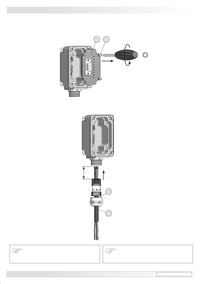
6.1.1. 3 Schritt 3 6 .1.1.3 Step 3
TX 10
* Siehe Seite 6 oder 7
See page 6 or 7
Zur Gewährleistung der angegebenen Schutzart sind nur geeignete
Kabeldurchmesser zu verwenden.
15
~75 mm
*
13c
*
17
ø5-13 mm
To ensure the specied protection
of the device the correct cable diameter must be used.
Baumer_HOG16M-DSL_II_DE-EN (17A1)
MB163 - 11055776
Page 19

Elektrischer Anschluss /Electricalconnection 6
6.1.1. 4 Schritt 4 6 .1.1.4 Step 4
Kabelschirm
Cable shield
13d
*
Ansicht X
siehe Abschnitt 6.1.4.
View X
see section 6.1.4.
6.1.1. 5 Schritt 5 6 .1.1.5 Step 5
D-SUB Buchse
13e
zum Anschluss an HOG 16 M,
siehe Abschnitt 6.1.1.6.
D-SUB connector (female)
for connecting to HOG 16 M,
se e sec t ion 6 .1.1.6.
22 mm
*
13c
*
TX 10
* Siehe Seite 6 oder 7
See page 6 or 7
MB163 - 11055776
Baumer_HOG16M-DSL_II_DE-EN (17A1)
*
17
16
Page 20

6 Elektrischer Anschluss/Electricalconnection
i
i
6.1.1. 6 Schritt 6 6 .1.1.6 Step 6
Zul. Anzugsmoment
Max. tightening torque
M
= 2-3 Nm
t
TX 20
13a
13b
*
*
13f
Zul. Anzugsmoment
Max. tightening torque
= 2-3 Nm
M
t
TX 20
*
13b
*
13a
*
*
13f
Großer, um 180° wendbarer
Klemmenkasten
Big terminal box, turn by 180°
* Siehe Seite 6
See page 6
17
Wir empfehlen, die Kombination so zu
montieren, dass der Kabelanschluss
keinem direkten Wassereintritt ausgesetzt ist.
It is recommended to mount the
combination with cable connection
facing downward and being not exposed to water.
Baumer_HOG16M-DSL_II_DE-EN (17A1)
MB163 - 11055776
Page 21

Elektrischer Anschluss /Electricalconnection 6
6.1.2 Beschreibung der Anschlüsse 6 .1. 2 Terminal signicance
+UB; +
; ; GND; 0V
;
K1; A; A+
K1
; A; A-
K2; B; B+
K2
; B; B-
K0; C; R; R+
K0
; C; R; R-
Betriebsspannung (für den Drehgeber)
Voltage supply (for the encoder)
Masseanschluss (für die Signale)
Ground (for the signals)
Erdungsanschluss (Gehäuse)
Earth ground (chassis)
Ausgangssignal Kanal 1
Output signal channel 1
Ausgangssignal Kanal 1 invertiert
Output signal channel 1 inverted
Ausgangssignal Kanal 2 (90° versetzt zu Kanal 1)
Output signal channel 2 (offset by 90° to channel 1)
Ausgangssignal Kanal 2 (90° versetzt zu Kanal 1) invertiert
Output signal channel 2 (offset by 90° to channel 1) inverted
Nullimpuls (Referenzsignal)
Zero pulse (reference signal)
Nullimpuls (Referenzsignal) invertiert
Zero pulse (reference signal) inverted
6.1.3 Ausgangssignale 6.1.3 Output signals
Signalfolge bei
positiver Drehrichtung,
siehe auch Abschnitt 5.
Sequence for positive
rotating direction,
see also section 5.
K1
K1
K2
K2
K0
K0
90°
6.1.4 Klemmenbelegung 6.1.4 Terminal assignment
Max. 1,5 mm
Max. AWG 16
2
K0
K0
K2
K2
Ansicht X
Anschlussklemmen,
siehe Abschnitt 6.1.1.4.
View X
Connecting terminal,
se e sec t ion 6 .1.1.4.
K1
K1
+UB
Zwischen und besteht keine Verbindung.
There is no connection between and .
Betriebsspannung nicht auf Ausgänge legen! Zerstörungsgefahr!
Spannungsabfälle in langen Leitungen
berücksichtigen (Ein- und Ausgänge).
MB163 - 11055776
Baumer_HOG16M-DSL_II_DE-EN (17A1)
18
Do not connect voltage supply to
outputs! Danger of damage!
Please, beware of possible voltage drop
in long cable leads (inputs and outputs).
Page 22

6 Elektrischer Anschluss/Electricalconnection
6.2 Klemmenkasten DSL.R,
Version für den Betrieb mit einem externen Relaismodul DS 93 R (Zubehör)
6.2 .1 Kabelanschluss
6.2 .1.1 Schritt 1
*
12d
22 mm
TX 20
12a
6.2 Klemmenkasten DSL.R,
version suitable for operation with the external relay module DS 93 R (accessory)
6. 2 .1 Cable connection
6. 2 .1.1 Step 1
*
*
12c
*
12b
* Siehe Seite 6
See page 6
19
Baumer_HOG16M-DSL_II_DE-EN (17A1)
MB163 - 11055776
Page 23

Elektrischer Anschluss /Electricalconnection 6
i
i
6.2.1.2 Schritt 2 6.2.1.2 Step 2
Zul. Anzugsmoment
Max. tightening torque
M
= 2-3 Nm
t
*
*
12e
12c
12b
*
*
Kabelschirm
Cable shield
22 mm
*
12d
ø5-13 mm
Ansicht Y
siehe Abschnitt 6.2.2.
View Y
see section 6.2.2.
TX 20
12a
* Siehe Seite 6 oder 7
See page 6 or 7
Zur Gewährleistung der angegebenen Schutzart sind nur geeignete
Kabeldurchmesser zu verwenden.
Wir empfehlen, die Kombination so
zu montieren, dass der Kabelanschluss keinem direkten Wassereintritt ausgesetzt ist.
MB163 - 11055776
Um 180° wendbarer Klemmenkasten
Terminal box, turn by 180°
Baumer_HOG16M-DSL_II_DE-EN (17A1)
To ensure the specied protection
of the device the correct cable diameter must be used.
It is recommended to mount the
combination with cable connection
facing downward and being not
exposed to water.
20
Page 24

6 Elektrischer Anschluss/Electricalconnection
6.2.2 Klemmenbelegung DSL.R
Version mit drei Schaltausgängen, welche
drehzahlabhängig geschaltet werden. Bei
Stillstand des Gerätes oder Drehzahl n
kleiner Schaltdrehzahl n
Schaltausgang high, bei n ≥ ns low.
ist der jeweilige
s
Bei Auftreten eines internen Fehlers (z. B.
einer Scheibenverschmutzung, so dass
die gezählte Impulsanzahl nicht stimmt)
schalten die Ausgänge auf low.
6.2.2
Terminal assignment DSL.R
Version with 3 switching outputs that can
be switched according to the speed. If
the device is at standstill or the rotational
speed n is less than the switching speed
then the corresponding switching output
n
s
will be high.Ifn≥ns then it will be low.
If an internal error occurs (for instance, dir t
on the disk, so that the counted pulse rate
is incorrect) then the outputs will switch to
low.
Ansicht Y
siehe Abschnitt 6.2.1.2.
View Y
see section 6.2.1.2.
R1, R2, R3, GND
Steuerleitungen zum Relaismodul DS 93 R (Zubehör)
Cable to relay module DS 93 R (accessory)
RS 485
Schnittstelle für PC oder Laptop (Adapter erforderlich). Programmierung des DSL über mitgelieferte
Software, siehe separates Benutzerhandbuch
„Software für digitalen Drehzahlschalter DSL“ auf
CD.
Interface for PC or Laptop (adapter required). Pro gramming of the DSL via the included software as
described in the separate user manual “Software
for the Digital Speed Switch DSL” on CD.
21
DS 93 R
Zubehör/Accessory
Baumer_HOG16M-DSL_II_DE-EN (17A1)
MB163 - 11055776
Page 25

Elektrischer Anschluss /Electricalconnection 6
6.2.3 Blockschaltbild 6.2.3
Kombination/Combination
15...30 VDC
High = 12 V, Low = 0 V
HOG 16 M
DSL.R
0 V (GND)
Block diagramm
0 V (GND)
A, B
R1
R2
R3
RS 485
für/for PC/Laptop
6.2.4 Ausgangsschaltverhalten 6.2.4
12 VDC
R
1,2,3
out
0 V (GND)
-n +n
-n
-ns off +ns off
s
on
n = Drehzahl/Speed
n
on
s
= Eingestellte Ein- und Ausschaltdrehzahl /Adjustedswitchingonandoffspeed
ns off
MB163 - 11055776
Baumer_HOG16M-DSL_II_DE-EN (17A1)
22
Switching characteristics
0
+ns on
Page 26

6 Elektrischer Anschluss/Electricalconnection
6.2.5 Version DS 93 R
Relaismodul (Zubehör)
6.2.5.1 Klemmenbelegung
3 Kontroll-LED‘s
3 control LEDs
3 Relais/relays
≤6 A / 250 VAC
≤1 A / 48 VDC
6.2.5.2 Anschlussschaltbild
R1
R2
R3
Cable from DSL.R
Leitungen vom DSL.R
0 V (GND)
6.2.5 Version DS 93 R
relay modul (accessory)
6.2.5.1 Terminal assignment
Höhe = 55 mm
Kunststoffgehäuse für
Tragschienenmontage (EN 50022) IP 20
Height = 55 mm
Plastic housing for
rail mounting (EN 50022) IP 20
6.2.5.2 Circuit diagram
2
3
4
6
11
13
12
14
16
15
17
19
18
DS 93RDSL.R
6.2.5.3 Ausgangsschaltverhalten
closed:
11-12, 14-15, 17-18
open:
12-13, 15-16, 18-19
-n
LED aus/out LED aus/outLED an/on
-nsoff +nsoff
n = Drehzahl/Speed
= Eingestellte Schaltdrehzahl /Adjustedswitchingspeed
n
s
Bitte beachten Sie, dass das Relaismodul DS 93 R (als Zubehör erhältlich) nicht in explosionsgefährdeten Bereichen zulässig ist.
23
6.2.5.3 Switching characteristics
closed:
12-13, 15-16, 18-19
open:
11-12, 14-15, 17-18
on 0 +nson
-n
s
Baumer_HOG16M-DSL_II_DE-EN (17A1)
closed:
11-12, 14-15, 17-18
open:
12-13, 15-16, 18-19
+n
Please take note that the relais
module DS 93 R (available as accessory) must not be used in potentionally explosive atmospheres.
MB163 - 11055776
Page 27

Elektrischer Anschluss /Electricalconnection 6
6.3 Klemmenkasten DSL.E,
Version mit drei internen elektronischen Relais
6.3.1 Kabelanschluss
6.3 .1.1 Schritt 1
22 mm
*
12d
TX 20
12a
6.3 Klemmenkasten DSL.E,
version with three internal electronic
relays
6. 3 .1 Cable connection
6. 3 .1.1 Step 1
*
*
12c
*
12b
* Siehe Seite 6
See page 6
MB163 - 11055776
Baumer_HOG16M-DSL_II_DE-EN (17A1)
24
Page 28

6 Elektrischer Anschluss/Electricalconnection
i
i
6.3.1.2 Schritt 2 6 .3.1.2 Step 2
Kabelschirm
Cable shield
22 mm
*
12d
ø5-13 mm
Ansicht Z
siehe Abschnitt 6.3.2.
View Z
see section 6.3.2.
12a
Zul. Anzugsmoment
Max. tightening torque
M
= 2-3 Nm
t
TX 20
*
*
12f
12c
12b
*
*
* Siehe Seite 6 oder 7
See page 6 or 7
Zur Gewährleistung der angegebenen Schutzart sind nur geeignete
Kabeldurchmesser zu verwenden.
Wir empfehlen, die Kombination so
zu montieren, dass der Kabelanschluss keinem direkten Wassereintritt ausgesetzt ist.
25
Um 180° wendbarer Klemmenkasten
Terminal box, turn by 180°
To ensure the specied protection
of the device the correct cable diameter must be used.
It is recommended to mount the
combination with cable connection
facing downward and being not
exposed to water.
Baumer_HOG16M-DSL_II_DE-EN (17A1)
MB163 - 11055776
Page 29

Elektrischer Anschluss /Electricalconnection 6
6.3.2 Klemmenbelegung DSL.E
Integrierte Stromuss-Überwachung bei
jedem Relais: Messung, ob bei geschlossenem Relais ein Strom (mind. 5 mA)
durch den geschalteten Stromkreis ießt.
Zwei Relaisausgänge (R1, R2) werden
drehzahlabhängig geschaltet. Bei Stillstand des Gerätes oder n<n
lige Relais geschlossen, bei n≥ns offen.
ist das jewei-
s
Dritter Relaisausgang (C1) als Kontroll-
Ausgang. Fließt bei mindestens einem Relaisausgang (R1, R2) trotz geschlossenem
Relais kein Strom durch den geschalteten
Stromkreis, wird der Kontroll-Ausgang (C1)
geöffnet.
Fließt bei geschlossenem Kontroll-Relais
(C1) kein Strom durch den geschalteten
Kontroll-Stromkreis, werden R1 und R2
geöffnet.
Bei internem Fehler (z. B. einer Scheiben-
verschmutzung, so dass die gezählte Impulsanzahl nicht stimmt) werden alle Relais geöffnet.
6.3.2
Terminal assignment DSL.E
Integrated current monitoring for each re-
lay: This checks whether, when the relay
isclosed, acurrentof at least 5 mA ows
through the switched circuit.
Two relay outputs (R1, R2) are switched
according to the speed. If the device is at
standstill or n<n
relayisclosed.Ifn≥ns then it will be open.
then the corresponding
s
The third relay output (C1) is a control out-
put.Ifnocurrentowsthroughatleastone
of the switched circuits of the relay outputs
(R1, R2), although the relay is closed, then
the control output (C1) will be opened.
If no current ows through the switched
circuit of the control relay (C1), although
the relay is closed, then R1 and R2 will be
opened.
If an internal error occurs (for instance, dir t
on the disk, so that the counted pulse rate
is incorrect) then all relays will be opened.
R1 (A+B), R2 (A+B)
Relaisausgänge drehzahlgesteuert
Relay outputs speed controlled
Ansicht Z
siehe Abschnitt 6.3.1.2.
View Z
see section 6.3.1.2.
MB163 - 11055776
Baumer_HOG16M-DSL_II_DE-EN (17A1)
C1 (A+B)
Kontrollausgang
Control output
RS 485
Schnittstelle für PC oder Laptop (Adapter erforderlich). Programmierung des DSL über mitgelieferte
Software, siehe separates Benutzerhandbuch
„Software für digitalen Drehzahlschalter DSL“ auf
CD.
Interface for PC or Laptop (adapter required). Pro gramming of the DSL via the included software as
described in the separate user manual “Software
for the Digital Speed Switch DSL” on CD.
26
Page 30

6 Elektrischer Anschluss/Electricalconnection
6.3.3 Blockschaltbild 6.3.3
Kombination/Combination
9...30 VDC
Kontrolle/control
HOG 16 M
0 V (GND)
6.4 Sensorkabel HEK 8 (Zubehör)
Es wird empfohlen, das Baumer Hübner
DSL.E
6.4 Sensor cable HEK 8 (accessory)
Sensorkabel HEK 8 zu verwenden oder ersatzweise ein geschirmtes, paarig verseiltes
Kabel. Das Kabel sollte in einem Stück und
getrennt von Motorkabeln verlegt werden.
Kabelabschluss:
Cable terminating resistance:
HTL: 1 ... 3 kΩ
TTL: 120 Ω
Block diagramm
C1-A
I>5 mA
C1-B
R1-A
I>5 mA
R1-B
R2-A
I>5 mA
R2-B
RS 485
A, B
für/for PC/Laptop
Baumer Hübner sensor cable HEK 8 is recommended. As a substitute a shielded twisted
pair cable should be used. Continuous wiring
without any splices or couplings should be used.
Separate signal cables from power cables.
HTL: 1...3kΩ
TTL: 120Ω
27
Rot/Red = +UB
Blau/Blue =
Weiß/White = K1
Braun/Brown = K1
Grün/Green = K2
Gelb/Yellow = K2
Grau/Grey = K0
Rosa/Pink = K0
Schwarz/Black = ---
Violett/Violet = ---
Aderendhülsen benutzen.
Use core-end ferrules.
Kabelschirm
Cable shield
Baumer_HOG16M-DSL_II_DE-EN (17A1)
MB163 - 11055776
Page 31

Betrieb und Wartung /Operationandmaintenance 7
7 Betrieb und Wartung
7.1 Austausch der Erdungsbürste
Bei Erreichen der minimalen Bürstenlänge
(L) von 5,3 mm sollte die Bürste ausgewechselt werden, damit weiterhin ein
einwandfreier Betrieb gewährleistet ist.
*
1 Stück Kohlebürste, als Zubehör erhältlich,
15
Bestellnummer 11058001
7 Operation and maintenance
7.1 Replace of the earthing brush
When the minimum brush length (L) of
5.3 mm is reached, the brush should be
replaced in order to ensure perfect operation.
*
1 piece carbon brush, available as accessory,
15
order number 11058001
* *
5 6
TX 20
*
14
15
*
* Siehe Seite 5
See page 5
MB163 - 11055776
Baumer_HOG16M-DSL_II_DE-EN (17A1)
L
28
Page 32

8 Demontage/Dismounting
8 Demontage
8.1 Schritt 1
TX 20
* **
13a13b
13f
8 Dismounting
8.1 Step 1
22 mm
*
12d
***
13f
13b13a
12c
TX 20
TX 20
*
*
12a
*
12b
* Siehe Seite 5, 6 oder 7
See page 5, 6 or 7
29
* *
13e 13d
TX 10
Baumer_HOG16M-DSL_II_DE-EN (17A1)
*
13c
*
17
22 mm
MB163 - 11055776
Page 33

Demontage /Dismounting 8
8.2 Schritt 2 8.2 Step 2
* *
13e 13d
TX 20
TX 10
22 mm
*
12c
*
13c
**
13a13b
22 mm
12d
13b13a
*
**
TX 20
TX 20
12a
12b
*
*
* Siehe Seite 5 oder 6
See page 5 or 6
MB163 - 11055776
Baumer_HOG16M-DSL_II_DE-EN (17A1)
30
Page 34

8 Demontage/Dismounting
8.3 Schritt 3 8.3 Step 3
8.4 Schritt 4 8.4 Step 4
*
6
TX 20
*
5
* Siehe Seite 5 oder 7
See page 5 or 7
31
18e
3 mm
**
34
*
11
*
18d
*
Baumer_HOG16M-DSL_II_DE-EN (17A1)
MB163 - 11055776
Page 35

Demontage /Dismounting 8
8.5 Schritt 5 8.5 Step 5
*
16
10 mm
* *
18a 18b
*
18c
8.6 Schritt 6 8.6 Step 6
* Siehe Seite 7
See page 7
MB163 - 11055776
Baumer_HOG16M-DSL_II_DE-EN (17A1)
32
Page 36

9 Technische Daten
9 Technische Daten
9.1 Technische Daten - elektrisch
• Betriebsstrom ohne Last: ≤200 mA
• Abtastprinzip: Optisch
• Störfestigkeit: EN 61000-6-2:2005
• Störaussendung: EN 61000-6-3:2007/A1:2011
• Zulassung: CE
HOG 16 M + DSL.E
• Betriebsspannung: 9...30 VDC
HOG 16 M + DSL.R
• Betriebsspannung: 15...30 VDC
9.2 Technische Daten - elektrisch (Drehgeber)
• Impulse pro Umdrehung: 512...2500 (Je nach Bestellung)
• Phasenverschiebung: 90° ±20°
• Tastverhältnis: 40…60 %
• Referenzsignal: Nullimpuls, Breite 90°
• Ausgabefrequenz: ≤120 kHz
• Ausgangssignale: K1, K2, K0 + invertierte
• Ausgangsstufen: HTL
TTL/RS422
(Je nach Bestellung)
9.3 Technische Daten - elektrisch (Drehzahlschalter)
• Schnittstelle: RS485
• Schaltgenauigkeit: ±2 % (Digit)
• Schaltverzögerung: ≤40 ms
HOG 16 M + DSL.E
• Schaltausgänge: 2 Ausgänge, drehzahlgesteuert
1 Kontrollausgang
• Ausgangsschaltleistung: 5...230 VAC/VDC; 5...250 mA
HOG 16 M + DSL.R
• Schaltausgänge: 3 Ausgänge, drehzahlgesteuert
• Ausgangsschaltleistung: 12 VDC; ≤40 mA
33
Baumer_HOG16M-DSL_II_DE-EN (17A1)
MB163 - 11055776
Page 37

9
9.4 Technische Daten - mechanisch
• Baugröße (Flansch): ø158 mm
• Wellenart: ø20...50 mm (durchgehende Hohlwelle)
• Zulässige Wellenbelastung: ≤ 450 N axial
≤600 N radial
• Schutzart DIN EN 60529: IP66
• Drehzahl (n): ≤6.000 U/min (mechanisch)
• Schaltdrehzahlbereich (n
Impulszahl = 1024: ±8...6000 U/min
): Impulszahl = 512: ±16...6000 U/min
s
Impulszahl = 2048: ±4...3500 U/min
Impulszahl = 2500: ±3...2900 U/min
• Betriebsdrehmoment: ≤15 Ncm
• Trägheitsmoment Rotor:
4,9 kgcm
2
• Werkstoffe: Gehäuse: Aluminium
Welle: Edelstahl
• Betriebstemperatur: -20…+85 °C
• Widerstandsfähigkeit: IEC 60068-2-6:2007
Vibration 15 g, 10-2000 Hz
IEC 60068-2-27:2008
Schock 300 g, 6 ms
• Anschluss: 3x Klemmenkasten
• Masse ca.: 5 kg
MB163 - 11055776
Baumer_HOG16M-DSL_II_DE-EN (17A1)
34
Page 38

9 Technical data
9 Technical data
9.1 Technical data - electrical ratings
• Consumptionw/oload: ≤200mA
• Sensing method: Optical
• Inter ference immunity: EN 61000-6-2:2005
• Emittedinter ference: EN61000 -6-3:2007/A1:2011
• Approval: CE
HOG 16 + DSL.E
• Voltage supply: 9...30 VDC
HOG 16 + DSL.R
• Voltage supply: 15...30 VDC
9.2 Technical data - electrical ratings (encoder)
• Pulses per revolution: 512...2500 (As ordered)
• Phase shift: 90° ±20°
• Duty cycle: 40...60 %
• Reference signal: Zero pulse, width 90°
• Outputfrequency: ≤120kHz
• Output signals: K1, K2, K0 + inverted
• Output stages: HTL
TTL /RS422
(As ordered)
9.3 Technical data - electrical ratings (speed switches)
• Interface: RS485
• Switching accuracy: ±2 % (Digit)
• Switchingdelaytime: ≤40ms
HOG 16 + DSL.E
• Switching outputs: 2 outputs, speed control
1 control output
• Outputswitchingcapacity: 5...230VAC/ VDC;5...250mA
HOG 16 + DSL.R
• Switching outputs: 3 outputs, speed control
• Outputswitchingcapacity: 12VDC;≤40mA
35
Baumer_HOG16M-DSL_II_DE-EN (17A1)
MB163 - 11055776
Page 39

9
9.4 Technical data - mechanical design
• Size(ange): ø158mm
• Shafttype: ø20...50mm(throughhollowshaft)
• Shaftloading: ≤450Naxial
≤600Nradial
• Protection DIN EN 60529: IP66
• Speed(n): ≤6000rpm
• Range of switching speed (n
Pulses = 1024: ±8...6000 rpm
): Pulses = 512: ±16...6000 rpm
s
Pulses = 2048: ±4...3500 rpm
Pulses = 2500: ±3...2900 rpm
• Operatingtorque: ≤15Ncm
• Rotor moment of inertia: 4.9 kgcm
2
• Materials: Housing: aluminium
Shaft: stainless steel
• Operating temperature: -20...+85 °C
• Resistance: IEC 60068-2-6:2007
Vibration15g,10-2000Hz
IEC 60068-2-27:2008
Shock 300 g, 6 ms
• Connection: 3x terminal box
• Weight approx.: 5 kg
MB163 - 11055776
Baumer_HOG16M-DSL_II_DE-EN (17A1)
36
Page 40

10 Zubehör / Accessories
10 Zubehör
10.1 Für die Kombination
• Drehmomentstütze Größe M12
Bestellnummer:
siehe Abschnitt 3.3.
• Montageset für Drehmomentstütze Größe M12 und Erdungsband, Bestellnummer: 11069336
• Erdungsbürste,
Bestellnummer: 11058001
• Werkzeugset,
Bestellnummer: 11068265
10.2 Für DSL
• Konverter USB ⇒ RS-485
• Relaismodul DS 93 R
(nur für DSL.R)
3 x Umschalter
(≤6 A/250 VAC; ≤1 A/48 VDC)
10.3 Für HOG 16 M
• Sensorkabel für Drehgeber
HEK 8
• Digital-Konverter:
HEAG 151 - HEAG 154
• LWL-Übertrager:
HEAG 171 - HEAG 176
• Prüfgerät für Drehgeber
HENQ 1100
10 Accessories
10.1 For the combination
*
16
*
18
*
15
*
19
10.2 For DSL
10.3 For HOG 16 M
*
17
• TorquearmsizeM12
order number:
see section 3.3.
• Mounting kit for torque arm
sizeM12andearthingstrap,
order number: 11069336
• Earthing brush,
order number: 11058001
• Tool kit,
order number: 11068265
• Converter USB ⇒ RS-485
• Relay module DS 93 R
(DSL.R version only)
3 x Change-over switch
(≤6A/250VAC;≤1A/48VDC)
• Sensor cable for encoders
HEK 8
• Digital converters:
HEAG 151 - HEAG 154
• Fiber optic links:
HEAG 171 - HEAG 176
• Analyzerforencoders
HEN Q 110 0
16
18
15
19
17
*
*
*
*
*
* Siehe Abschnitt 3 * See section 3
Baumer Hübner GmbH
P.O. Box 12 69 43 · 10609 Berlin, Germany
Phone: +49 (0)30/69003-0 · Fax: +49 (0)30/69003-104
info@baumerhuebner.com · www.baumer.com/motion
Version:
74263, 742 67
37
Baumer_ HOG16M -DSL _II _DE- EN (17A1 - 12.07.2017)
Originalsprache der Anleitung ist Deutsch.
Technische Änderungen vorbehalten.
Original language of this instruction is German.
Technical modications reser ved.
MB163 - 11055776
 Loading...