


Manual
Absolute Encoder with CANopen
Firmware version from 1.00
Baumer IVO GmbH & Co. KG |
|
Dauchinger Strasse 58-62 |
|
DE-78056 Villingen-Schwenningen |
|
Phone +49 7720 942-0 |
|
Fax +49 7720 942-900 |
11.12 · 174.02.030/9 |
info.de@baumerivo.com |
Subject to modification in technic and design. |
www.baumer.com |
Errors and omissions excepted. |

Contents
|
|
|
Page |
1. |
Introduction |
3 |
|
1.1. |
|
Scope of delivery |
3 |
1.2. |
|
Product assignment |
3 |
2. Safety and operating instructions |
4 |
||
3. CAN bus and CANopen communication |
5 |
||
3.1. |
|
CAN bus |
5 |
3.1.1. |
CAN bus characteristics |
5 |
|
3.2. |
|
CANopen |
6 |
3.3. |
|
CANopen communication |
7 |
3.3.1. |
Communication profile |
7 |
|
3.3.2. |
CANopen message structure |
7 |
|
3.3.3. |
Service data communication |
8 |
|
3.3.4. |
Process data communication |
9 |
|
3.3.5. |
Emergency service |
11 |
|
3.3.6. |
Network management services |
12 |
|
3.4. |
|
Encoder profile |
19 |
3.4.1. |
Overview of encoder objects |
19 |
|
3.4.2. |
Detailed object list (DS-301) |
23 |
|
4. Diagnosis and useful information |
39 |
||
4.1. |
|
Error diagnosis field bus communication |
39 |
4.2. |
|
Error diagnosis via field bus |
39 |
4.3. |
|
Useful information relating to the sensor |
40 |
5. |
Applications |
41 |
|
5.1. |
|
Setting and reading objects |
41 |
5.2. |
|
Configuration |
42 |
5.3. |
|
Operation |
43 |
5.4. |
|
Use the encoder via CAN interface |
45 |
6. Terminal assignment and commissioning |
47 |
||
6.1. |
|
Mechanical mounting |
47 |
6.2. |
|
Electrical connection |
47 |
6.2.1. |
Contact description |
47 |
|
6.2.2. |
Pin assignment M12 connector |
47 |
|
6.2.3. |
Pin assignment D-SUB connector |
48 |
|
6.3. |
|
Display elements (status display) |
48 |
Manual_G0-GB-GXP5-GXU5_406_EN.docx |
2/48 |
Baumer IVO GmbH & Co. KG |
20.11.12 |
|
Villingen-Schwenningen, Germany |

Disclaimer of liability
The present manual was compiled with utmost care, errors and omissions reserved. For this reason Baumer IVO GmbH & Co. KG rejects any liability for the information compiled in the present manual.
Baumer IVO nor the author will accept any liability for direct or indirect damages resulting from the use of the present information.
At any time we should be pleased receiving your comments and proposals for further improvement of the present document.
1. Introduction
1.1. Scope of delivery
Please check the delivery upon completeness prior to commissioning. Depending on encoder configuration and part number delivery is including:  Encoder
CD with describing file and manual (also available as download in the Internet)
1.2. Product assignment
Shaft encoders
|
Product |
|
|
Product code |
|
|
Device name |
|
|
Eds file |
|
|
Product family |
|
|
|
|
|
|
|
|
|
|
|
|||||
GBP5W |
|
0x18 |
|
GBP5 |
|
GBP5_406.eds |
|
Multiturn |
||||||
|
|
|
|
|
|
|
|
|
||||||
GBU5W |
|
0x19 |
|
GBU5 |
|
GBU5_406.eds |
|
Singleturn |
||||||
|
|
|
|
|
|
|
|
|
||||||
GXP5W |
|
0x14 |
|
GXP5 |
|
GXP5_406.eds |
|
Multiturn |
||||||
|
|
|
|
|
|
|
|
|
||||||
GXU5W |
|
0x15 |
|
GXU5 |
|
GXU5_406.eds |
|
Singleturn |
||||||
|
|
|
|
|
|
|
|
|
||||||
X 700 |
|
0x14 |
|
GXP5 |
|
GXP5_406.eds |
|
Multiturn |
||||||
|
|
|
|
|
|
|
|
|
|
|
||||
End shaft encoders |
|
|
|
|
|
|
|
|
|
|||||
|
|
|
|
|
|
|
|
|
||||||
|
Product |
|
|
Product code |
|
|
Device name |
|
|
Eds file |
|
|
Product family |
|
GBP5S |
|
0x18 |
|
GBP5 |
|
GBP5_406.eds |
|
Multiturn |
||||||
|
|
|
|
|
|
|
|
|
||||||
GBU5S |
|
0x19 |
|
GBU5 |
|
GBU5_406.eds |
|
Singleturn |
||||||
|
|
|
|
|
|
|
|
|
||||||
GXP5S |
|
0x14 |
|
GXP5 |
|
GXP5_406.eds |
|
Multiturn |
||||||
|
|
|
|
|
|
|
|
|
||||||
GXU5S |
|
0x15 |
|
GXU5 |
|
GXU5_406.eds |
|
Singleturn |
||||||
|
|
|
|
|
|
|
|
|
|
|
||||
Hollow shaft encoders |
|
|
|
|
|
|
|
|
|
|||||
|
|
|
|
|
|
|
|
|
||||||
|
Product |
|
|
Product code |
|
|
Device name |
|
|
Eds file |
|
|
Product family |
|
G0P5H |
|
0x14 |
|
GXP5 |
|
GBP5_406.eds |
|
Multiturn |
||||||
|
|
|
|
|
|
|
|
|
||||||
GBP5H |
|
0x18 |
|
GBP5 |
|
GBP5_406.eds |
|
Multiturn |
||||||
|
|
|
|
|
|
|
|
|
|
|
|
|
|
|
Manual_G0-GB-GXP5-GXU5_406_EN.docx |
3/48 |
Baumer IVO GmbH & Co. KG |
20.11.12 |
|
Villingen-Schwenningen, Germany |

2. Safety and operating instructions
Supplementary information
This manual is intended as a supplement to already existing documentation (catalogues, product information or assembly instructions).
The manual must be read without fail before initial commissioning of the equipment.
Intended purpose of the equipment
The encoder is a precision measurement device. It is used to determine angular positions and revolutions, and to prepare and supply measured values in the form of electrical output signals for the follow-on device systems. The encoder may only be used for this purpose.
Commissioning
The encoder may only be installed and assembled by suitably qualified experts. Observe the operating instructions of the machine manufacturer.
Safety remarks
Prior to commissioning the equipment, check all electrical connections.
If installation, electrical connection or any other work performed at the encoder or at the equipment is not correctly executed, this can result in a malfunction or failure of the encoder.
Steps must be taken to exclude any risk of personal injury, damage to the plant or to the operating equipment as a result of encoder failure or malfunction by providing suitable safety precautions. Encoders must not be operated outside the specified limited values (see detailed product documentation).
Failure to comply with the safety remarks can result in malfunctions, personal injury or damage to property.
Transport and storage
Only ever transport or store encoders in their original packaging.
Never drop encoders or expose them to major vibrations.
Assembly
Avoid impacts or shocks on the housing and shaft / hollow shaft
Avoid any twist or torsion on the housing.
Never make rigid connections between the encoder shaft and drive shaft.
Do not open the encoder or make any mechanical changes to it.
The shaft, ball bearings, glass pane or electronic components can be damaged. In this case, safe and reliable operation cannot be guaranteed.
Electrical commissioning
Do not make any electrical changes at the encoder.
Do not carry out any wiring work when the encoder is live.
Never plug or unplug the electrical connection when the encoder is live.
Ensure that the entire plant is installed in line with EMC requirements. The installation environment and wiring affect the electromagnetic compatibility of the encoder. Install the encoder and supply cables separately or at a long distance from cables with high interference emissions (frequency converters, contactors etc.)
Where working with consumers which have high interference emissions, make available a separate power supply for the encoder.
Completely shield the encoder housing and connecting cable.
Connect the encoder to the protective earth (PE) conductor using shielded cable. The braided shield must be connected to the cable gland or plug. Ideally, aim at bilateral connection to protective earth (PE), the housing via the mechanical assembly, the cable shield via the downstream connected devices. In case of earth loop problems, earth on one side only as a minimum requirement.
Failure to observe these instructions can result in malfunctions, material damage or personal injury.
Manual_G0-GB-GXP5-GXU5_406_EN.docx |
4/48 |
Baumer IVO GmbH & Co. KG |
20.11.12 |
|
Villingen-Schwenningen, Germany |

3. CAN bus and CANopen communication
3.1. CAN bus
The CAN bus (CAN: Controller Area Network) was originally developed by Bosch and Intel as a means of fast, low-cost data transmission in automotive applications. The CAN bus is used today also in industrial automation applications.
The CAN bus is a field bus (the standards are defined by the CAN in Automation (CiA) Association) through which devices, actuators and sensors from different manufacturers can communicate with each other.
3.1.1. CAN bus characteristics
•Data rate of 1 MBaud with network expansion up to 40 m
•Network connected on both sides
•The bus medium is a twisted-pair cable
•Real time capability: Defined maximum waiting time for high-priority messages.
•Theoretically 127 users at one bus, but physically only 32 are possible (due to the driver).
•Ensures data consistency across the network. Damaged messages are notified as faulty for all network nodes.
•Message-oriented communication
The message is identified by a message identifier. All network nodes use the identifier to test whether the message is of relevance for them.
•Broadcasting, multicasting
All network nodes receive each message simultaneously. Synchronization is therefore possible.
•Multimaster capability
Each user in the field bus is able to independently transmit and receive data without being dependent upon the priority of the master. Each user is able to start its message when the bus is not occupied. When messages are sent simultaneously, the user with the highest priority prevails.
•Prioritization of messages
The identifier defines the priority of the message. This ensures that important messages are transmitted quickly via the bus.
•Residual error probability
Safety procedures in the network reduce the probability of an undiscovered faulty data transmission to below 10 -11. In practical terms, it is possible to ensure a 100% reliable transmission.
•Function monitoring
Localization of faulty or failed stations. The CAN protocol encompasses a network node monitoring function. The function of network nodes which are faulty is restricted, or they are completely uncoupled from the network.
•Data transmission with short error recovery time
By using several error detection mechanisms, falsified messages are detected to a high degree of probability. If an error is detected, the message transmission is automatically repeated.
In the CAN Bus, several network users are connected by means of a bus cable. Each network user is able to transmit and receive messages. The data between network users is serially transmitted.
Examples of network users for CAN bus devices are:
•Automation devices such as PLCs
•PCs
•Input and output modules
•Drive control systems
•Analysis devices, such as a CAN monitor
•Control and input devices as Human Machine Interfaces (HMI)
•Sensors and actuators
Manual_G0-GB-GXP5-GXU5_406_EN.docx |
5/48 |
Baumer IVO GmbH & Co. KG |
20.11.12 |
|
Villingen-Schwenningen, Germany |

3.2. CANopen
Under the technical management of the Steinbeis Transfer Centre for Automation, the CANopen profile was developed on the basis of the Layer 7 specification CAL (CAN Application Layer). In comparison with CAL, CANopen only contains the functions suitable for this application. CANopen thus represents only a partial function of CAL optimized for the application in hand, so permitting a simplified system structure and the use of simplified devices. CANopen is optimized for fast data exchange in real time systems.
The organization CAN in Automation (CiA) is responsible for the applicable standards of the relevant profiles. CANopen permits:
•Simplified access to all device and communication parameters
•Synchronization of several devices
•Automatic configuration of the network
•Cyclical and event-controlled process data communication
CANopen comprises four communication objects (COB) with different characteristics:
•Process data objects for real time data (PDO)
•Service data objects for parameter and program transmission (SDO)
•Network management (NMT, Heartbeat)
•Pre-defined objects (for synchronization, emergency message)
All device and communication parameters are subdivided into an object directory. An object directory encompasses the name of the object, data type, number of subindexes, structure of the parameters and the address. According to CiA, this object directory is subdivided into three different parts. Communication profile, device profile and a manufacturer-specific profile (see object directory).
Manual_G0-GB-GXP5-GXU5_406_EN.docx |
6/48 |
Baumer IVO GmbH & Co. KG |
20.11.12 |
|
Villingen-Schwenningen, Germany |

3.3. CANopen communication
3.3.1. Communication profile
Communication between the network users and the Master (PC / Control) takes place by means of object directories and objects. The objects are addressed via a 16 bit index. The CANopen communication profile DS 301 standardizes the various communication objects. They are accordingly divided into several groups:
•Process data objects PDO for real time transmission of process data
•Service data objects SDO for read/write access to the object directory
•Objects for synchronization and error display of CAN users:
SYNC object (synchronization object) for synchronization of network users
EMCY object (emergency object) for error display of a device or its peripherals
•Network management NMT for initialization and network control
•Layer Setting Services LSS for configuration by means of serial numbers, revision numbers etc. in the middle
of an existing network
3.3.2. CANopen message structure
The first part of a message is the COB ID (Identifier). Structure of the 11-bit COB ID :
Function code |
Node ID |
|||||||||
4-bit function code |
7-bit node ID |
|||||||||
|
|
|
|
|
|
|
|
|
|
|
The function code provides information on the type of message and priority
The lower the COB ID, the higher the priority of the message
Broadcast messages:
Function code |
|
COB ID |
|
|
||
NMT |
|
0 |
|
|
|
|
SYNC |
|
80h |
|
|
|
|
Peer to peer messages: |
|
|
|
|||
|
|
|
|
|||
Function code |
|
COB ID |
|
|||
Emergency |
|
|
80h |
+ Node ID |
|
|
PDO1 (tx)1) |
|
180h |
+ Node ID |
|
||
PDO2 (tx)1) |
|
280h |
+ Node ID |
|
||
SDO (tx)1) |
|
580h |
+ Node ID |
|
||
SDO (rx)1) |
|
600h |
+ Node ID |
|
||
Heartbeat |
|
700h |
+ Node ID |
|
||
LSS (tx) 1) |
|
7E4h |
|
|
|
|
LSS (rx) 1) |
|
7E5h |
|
|
1): (tx) and (rx) from the viewpoint of the encoder |
|
The node ID can be freely selected by means of the CANopen bus between 1 and 127 (if encoder = 0). The encoders are supplied with the Node ID 1.
This can be changed with the service data object 2101h or using LSS.
A CAN telegram is made up of the COB ID and up to 8 bytes of data:
COB ID |
DLC |
|
Byte 1 |
Byte 2 |
Byte 3 |
Byte 4 |
Byte 5 |
Byte 6 |
Byte 7 |
Byte 8 |
Xxx |
x |
|
xx |
xx |
xx |
xx |
xx |
xx |
xx |
xx |
The precise telegram is outlined in more detail at a later point.
Manual_G0-GB-GXP5-GXU5_406_EN.docx |
7/48 |
Baumer IVO GmbH & Co. KG |
20.11.12 |
|
Villingen-Schwenningen, Germany |

3.3.3. Service data communication
The service data objects correspond to the standards of the CiA. It is possible to access an object via index and subindex. The data can be requested or where applicable written into the object.
General information on the SDO
Structure of an SDO telegram:
COB ID |
DLC |
Command |
Object L |
Object H |
Subindex |
Data 0 |
Data 1 |
Data 2 |
Data 3 |
An SDO-COB ID is composed as follows: |
|||||||||
Master -> Encoder |
: 600h + Node ID |
||||||||
Encoder -> Master |
: 580h + Node ID |
||||||||
DLC (data length code) describes the length of the telegram. This is composed as follows: 1 byte command + 2 bytes object + 1 byte subindex + no. of data bytes (0 - 4).
The command byte defines whether data is read or set, and how many data bytes are involved.
SDO command |
Description |
Data length |
|
22h |
Download request |
Max. 4 Byte |
Transmits parameter to encoder |
23h |
Download request |
4 byte |
|
2Bh |
Download request |
2 byte |
|
2Fh |
Download request |
1 byte |
|
|
|
|
|
60h |
Download response |
- |
Confirms receipt to master |
40h |
Upload request |
- |
Requests parameter from encoder |
|
|
|
|
42h |
Upload response |
Max. 4 byte |
Parameter to master with max. 4 byte |
43h |
Upload response |
4 byte |
|
4Bh |
Upload response |
2 byte |
|
4Fh |
Upload response |
1 byte |
|
|
|
|
|
80h |
Abort message |
- |
Encoder signals error code to master |
An abort message indicates an error in the CAN communication. The SDO command byte is 80h. The object and subindex are those of the requested object. The error code is contained in bytes 5 – 8.
ID |
|
DLC |
Byte 1 |
Byte 2 |
Byte 3 |
|
Byte 4 |
Byte 5 |
Byte 6 |
Byte 7 |
Byte 8 |
|
580h + Node ID |
8 |
80h |
Object L |
Object H |
|
Subindex |
ErrByte 0 |
ErrByte 1 |
ErrByte 2 |
ErrByte 3 |
||
Byte 8..5 results in the SDO abort message (byte 8 = MSB). |
|
|
|
|
||||||||
The following messages are supported: |
|
|
|
|
|
|
|
|||||
|
05040001h |
: Command byte is not supported |
|
|
|
|
||||||
|
06010000h |
: Incorrect access to an object |
|
|
|
|
|
|||||
|
06010001h |
: Read access to write only |
|
|
|
|
|
|||||
|
06010002h |
: Write access to read only |
|
|
|
|
|
|||||
|
06020000h |
: Object is not supported |
|
|
|
|
|
|||||
|
06090011h |
: Subindex is not supported |
|
|
|
|
|
|||||
|
06090030h |
: Value outside the limit |
|
|
|
|
|
|||||
|
06090031h |
: Value too great |
|
|
|
|
|
|
|
|||
|
08000000h |
: General error |
|
|
|
|
|
|
|
|||
|
08000020h |
: Incorrect save signature |
|
|
|
|
|
|||||
|
08000021h |
: Data cannot be stored |
|
|
|
|
|
|||||
Manual_G0-GB-GXP5-GXU5_406_EN.docx |
8/48 |
Baumer IVO GmbH & Co. KG |
20.11.12 |
|
Villingen-Schwenningen, Germany |

SDO examples
Request of a value by the master from the slave
A frequent request will be a request for position. Object 6004h
COB ID |
DLC |
Command |
Object L |
Object H |
Subindex |
Data 0 |
Data |
|
Data |
Data |
|
|
|
|
|
|
|
|
1 |
|
2 |
3 |
|
600h+node ID |
8 |
40h |
04h |
60h |
0 |
x |
x |
|
x |
x |
|
Response by the slave to the request for a value |
|
|
|
|
|
|
|
|
|||
The position is 4 bytes long, the precise values can be found under object 6004h. |
|
|
|
|
|
||||||
|
|
|
|
|
|
|
|
|
|
|
|
COB ID |
DLC |
Command |
Object L |
Object H |
Subindex |
Data 0 |
Data |
|
Data |
Data |
|
|
|
|
|
|
|
|
1 |
|
2 |
3 |
|
580h+node ID |
8 |
43h |
04h |
60h |
0 |
a |
b |
|
c |
d |
|
Writing of a value by the master into the slave |
|
|
|
|
|
|
|
|
|||
Position setting can be performed with preset. Object 6003h |
|
|
|
|
|
|
|||||
|
|
|
|
|
|
|
|
|
|
|
|
COB ID |
DLC |
Command |
Object L |
Object H |
Subindex |
Data 0 |
Data |
|
Data |
Data |
|
|
|
|
|
|
|
|
1 |
|
2 |
3 |
|
600h+node ID |
8 |
22h |
03h |
60h |
0 |
a |
b |
|
c |
d |
|
Slave's response to the writing of a value |
|
|
|
|
|
|
|
|
|||
|
|
|
|
|
|
|
|
|
|
|
|
COB ID |
DLC |
Command |
Object L |
Object H |
Subindex |
Data 0 |
Data |
|
Data |
Data |
|
|
|
|
|
|
|
|
1 |
|
2 |
3 |
|
580h+node ID |
8 |
60h |
03h |
60h |
0 |
0 |
0 |
0 |
0 |
|
|
3.3.4. Process data communication
Process data objects are used for real time data exchange for process data, for example position or operating status. PDOs can be transmitted synchronously or cyclically (asynchronously). The encoder supports the PDO1 and the PDO2. Both PDOs supply the current position of the encoder and are defined in the objects 1800h, 1801h, 1A00h, 1A01, 2800h, 2801h and 6200h.
Synchronous
In order to transmit the process data synchronously, a value between 1 and F0h (=240) must be written into the object 1800h / 1801h Subindex 2. If the value is 3, the PDO is transmitted on every third sync telegram (if the value 1 is entered, transmission takes place on every sync telegram), as long as there is a 0 written into the object 2800h / 2801h. If it contains for example a 5, the PDO will continue to be written as before on every third Sync telegram, but only a total of 5 times. Accordingly, the last PDO is written on the 15th sync telegram. The counter for the number of PDOs to be transmitted is reset in the event of a position change or NMT reset, i.e. unless it is changed, the position is transmitted five times. If the position changes, it is transmitted a further five times.
In synchronous operation, the PDO is requested by the master via the Sync telegram.
Byte 0 |
Byte 1 |
COB ID = 80 |
0 |
Cyclical (asynchronous)
If you wish the PDOs to be transmitted cyclically, the value FEh must be written into the object 1800h / 1801h Subindex 2. In addition, the cycle time in milliseconds must be entered in the same object subindex 5. The entered time is rounded off to 1 ms. If the value is stored for 0 ms, the PDOs are not transmitted. The function is switched off.
The object 2800h / 2801h offers another possibility: If the value is 0, cyclical transmission runs as described above. If the value is 1, a cyclical test is performed as to whether a change of the value has occurred. If not, no transmission takes place. If the value is 4, the PDO is transmitted four times with each cycle if there is a change.
Manual_G0-GB-GXP5-GXU5_406_EN.docx |
9/48 |
Baumer IVO GmbH & Co. KG |
20.11.12 |
|
Villingen-Schwenningen, Germany |

Overview
In the following table, the different transmission modes for PDOs are summarized:
|
1800h |
|
|
2800h |
|
|
Summarized description |
|
|||
|
Sub2 |
|
|
Sub5 |
|
|
|
|
|
||
|
|
|
|
|
|
|
|
|
|
||
|
FEh |
|
|
3ms |
|
0 |
|
|
Cyclical transmission every 3 ms |
||
|
FEh |
|
|
5ms |
|
2 |
|
|
Every 5 ms, the PDO is sent twice if there is a change |
||
|
FEh |
|
|
0ms |
|
0 |
|
|
Transmit PDO switched off |
||
|
FEh |
|
|
0ms |
|
|
xxx |
|
Transmit PDO switched off |
||
3 |
|
|
xxx |
|
0 |
|
|
Transmit with every third sync telegram |
|||
3 |
|
|
xxx |
|
|
2Bh |
|
On every third sync telegram, but only 43 times in total (=2Bh). |
|||
PDO (Position)
PDO1 telegram structure:
ID |
|
DLC |
|
Byte 1 |
|
Byte 2 |
Byte 3 |
Byte 4 |
181h |
|
4 |
|
Xx |
|
Xx |
Xx |
Xx |
ID |
|
: 180h + node ID |
|
|
||||
Length |
|
: 4 DataByte |
|
|
|
|||
Byte1 - 4 |
|
: Current position in increments |
|
|||||
PDO2 telegram structure: |
|
|
|
|||||
|
|
|
|
|
|
|
||
ID |
|
DLC |
|
Byte 1 |
|
Byte 2 |
Byte 3 |
Byte 4 |
281h |
|
4 |
|
Xx |
|
Xx |
Xx |
Xx |
ID |
|
: 280h + node ID |
|
|
||||
Length |
|
: 4 DataByte |
|
|
|
|||
Byte1 - 4 |
|
: Current position in increments |
|
|||||
Manual_G0-GB-GXP5-GXU5_406_EN.docx |
10/48 |
Baumer IVO GmbH & Co. KG |
20.11.12 |
|
Villingen-Schwenningen, Germany |
3.3.5. Emergency service
Internal device error or bus problems initiate an emergency message:
COB-ID |
DLC |
Byte0 |
|
Byte 1 |
|
|
Byte 2 |
|
Byte 3 |
Byte 4 |
|
Byte 5 |
|
Byte 6 |
Byte 7 |
|||
80h+Node-ID |
8 |
|
Error Code |
|
Errorregister |
|
Alarms 6503h |
|
Warning 6505h |
- |
||||||||
|
|
|
00h |
|
01h |
|
|
1001h |
|
|
|
|
|
|
|
|
|
|
Byte 0..1: Error Codes |
|
|
|
|
|
|
|
|
|
|
|
|
|
|
||||
Error Code (hex) |
|
Meaning |
|
|
|
|
|
|
|
|
|
|
|
|
|
|
||
0000 |
|
|
Error Reset or No Error |
|
|
|
|
|
|
|
|
|||||||
1000 |
|
|
Generic Error |
|
|
|
|
|
|
|
|
|
|
|
|
|||
5530 |
|
|
EEPROM error (from V1.04+) |
|
|
|
|
|
|
|
|
|||||||
6010 |
|
|
Software reset (Watchdog) (from V1.04+) |
|
|
|
|
|
|
|
||||||||
7320 |
|
|
Position error (from V1.04+) |
|
|
|
|
|
|
|
|
|||||||
7510 |
|
|
Internal communication error (from V1.04+) |
|
|
|
|
|
|
|
||||||||
8130 |
|
|
Life Guard error or Hearbeat error (from V1.04+) |
|
|
|
|
|||||||||||
FF00 |
|
|
Battery low (from V1.04+) |
|
|
|
|
|
|
|
|
|||||||
Byte 2: Error-Register |
|
|
|
|
|
|
|
|
|
|
|
|
|
|
||||
Bit |
|
|
Meaning |
|
|
|
|
|
|
|
|
|
|
|
|
|
|
|
0 |
|
|
Generic Error |
|
|
|
|
|
|
|
|
|
|
|
|
|||
4 |
|
|
Communication error (V1.04) |
|
|
|
|
|
|
|
|
|||||||
7 |
|
|
manufacturer specific (V1.04) |
|
|
|
|
|
|
|
|
|||||||
Byte 3..4 Alarms |
|
|
|
|
|
|
|
|
|
|
|
|
|
|
|
|
||
Bit |
|
|
Meaning |
|
|
|
|
Wert = 0 |
|
Wert = 1 |
|
|
|
|
||||
0 |
|
|
Position error aktiv |
|
|
Nein |
|
|
Ja |
|
|
|
|
|||||
Byte 5..6 Warning |
|
|
|
|
|
|
|
|
|
|
|
|
|
|
|
|
||
Bit |
|
|
Meaning |
|
|
|
|
Wert = 0 |
|
Wert = 1 |
|
|
|
|
||||
2 |
|
|
CPU watchdog status |
|
OK |
|
|
Reset done |
|
|
|
|||||||
4 |
|
|
Battery charge |
|
|
OK |
|
|
Battery low |
|
|
|
||||||
Byte 7: not used
Manual_G0-GB-GXP5-GXU5_406_EN.docx |
11/48 |
Baumer IVO GmbH & Co. KG |
20.11.12 |
|
Villingen-Schwenningen, Germany |
3.3.6. Network management services
Network management can be divided into two groups.
Using the NMT services for device monitoring, bus users can be initialized, started and stopped. In addition, NMT services exist for connection monitoring.
Description of the NMT command
The commands are transmitted as unconfirmed objects and are structured as follows:
Byte 0 |
Byte 1 |
Byte 2 |
COB ID = 0 |
Command byte |
Node number |
The COB ID for NMT commands is always zero. The node ID is transmitted in byte 2 of the NMT command.
Command byte
Command byte |
Description |
In state event drawing |
01h |
Start remote node |
1 |
02h |
Stop remote node |
2 |
80h |
Enter pre-operational mode |
3 |
81h, 82h |
Reset remote node |
4, 5 |
The node number corresponds to the node ID of the required users. With node number = 0, all users are addressed.
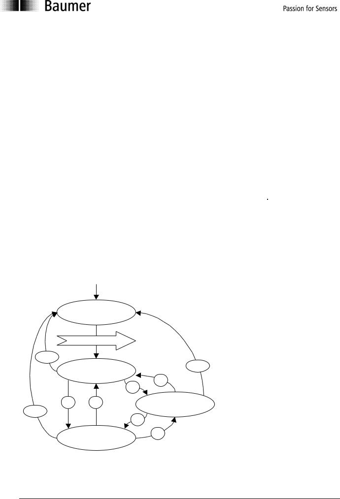
NMT state event
Following initialization, the encoder is in the pre-operational mode. In this status, SDO parameters can be read and written. In order to request PDO parameters, the encoder must first be moved to the operational mode status.
Power on or hardware reset
Init |
|
BootUp Message |
|
4/5 |
|
Pre-Operational |
4/5 |
|
|
|
3 |
|
|
2 |
1 |
3 |
Stopped/Prepared |
4/5 |
|
|
|
|
1 |
|
Operational |
2 |
|
|
Manual_G0-GB-GXP5-GXU5_406_EN.docx |
12/48 |
Baumer IVO GmbH & Co. KG |
20.11.12 |
|
Villingen-Schwenningen, Germany |

The various NMT statuses
Init
Following initalization, the encoder logs on to the CAN bus with a BootUp message. The encoder then goes automatically to the pre-operational mode status.
The COB ID of the BootUp message is made up of 700h and the node ID.
COB ID |
Byte 0 |
700h + node ID |
00 |
Pre-operational mode
In the pre-operational mode, SDOs can be read and written.
Operational mode
In the operational mode, the encoder transmits the requested PDOs. In addition, SDOs can be read and written.
Stopped or prepared mode
In the stopped mode, only NMT communication is possible. No SDO parameters can be read or set. LSS is only possible in the stopped mode.
Status change
Start remote node (1)
With the start command, the encoder is switched to the operational mode status.
COB ID |
Command byte |
Node number |
0 |
1h |
0..127 |
Stop remote node (2)
With the stop command, the encoder is switched to the stopped or prepared mode status.
COB ID |
Command byte |
Node number |
0 |
2h |
0..127 |
Enter pre-operational mode (3)
Change to the pre-operational mode status.
COB ID |
Command byte |
Node number |
0 |
80h |
0..127 |
Reset remote node (4) or reset communication (5)
With the reset command, the encoder is re-initialized.
Reset remote node (4):
COB ID |
Command byte |
Node number |
0 |
81h |
0..127 |
Reset communication (5): |
|
|
|
|
|
COB ID |
Command byte |
Node number |
0 |
82h |
0..127 |
Manual_G0-GB-GXP5-GXU5_406_EN.docx |
13/48 |
Baumer IVO GmbH & Co. KG |
20.11.12 |
|
Villingen-Schwenningen, Germany |

Node and Life Guarding
"Communication error Object 1029h-1h".
Example for a nodeguarding protocol:
COB-ID |
Data/ Remote |
Byte 0 |
701h |
r |
00h (0d) |
701h |
d |
FFh (255d) |
701h |
r |
00h (0d) |
701h |
d |
7Fh (127d) |
Possible NMT node states:
0:BootUp-Event
4:Stopped
5:Operational
127:Pre-operational
The „CAN in Automation“ association CiA recommend to use the new heartbeat protocol (see next chapter).
To use the node guarding instead of heartbeat protocol bit 5 of object 2110h has to be set.
To detect absent devices (e.g. because of bus-off) that do not transmit PDOs regularly, the NMT Master can manage a database, where besides other information the expected states of all connected devices are recorded, which is known as Node Guarding. With cyclic node guarding the NMT master regularly polls its NMT slaves. To detect the absence of the NMT master, the slaves test internally, whether the Node Guarding is taking place in the defined time interval (Life Guarding). The Node Guarding is initiated by the NMT Master in Pre-Operational state of the slave by transmitting a Remote Frame.
The NMT Master regularly retrieves the actual states of all devices on the network by a Remote Frame and compares them to the states recorded in the network database. Mismatches are indicated first locally on the NMT Master through the Network Event Service. Consequently the application must take appropriate actions to ensure that all devices on the bus will got to a save state
in other words, the encoder is in the pre-operational mode (7Fh = 127).
Manual_G0-GB-GXP5-GXU5_406_EN.docx |
14/48 |
Baumer IVO GmbH & Co. KG |
20.11.12 |
|
Villingen-Schwenningen, Germany |

Heartbeat protocol
object 1029h-1h".
Example for a heartbeat protocol
COB-ID |
Data/Remote |
Byte 0 |
701h |
d |
7Fh (127d) |
The optional heartbeat protocol should substitute the life/node guarding protocol. Heartbeat ist aktiv, wenn im Objekt 2110h Bit5 auf '0' ist. It is highly recommend to implement for new device designs the heartbeat protocol. A Heartbeat Producer transmits the Heartbeat message cyclically with the frequency defined in Heartbeat producer time object. One or more Heartbeat Consumer may receive the indication. The relationship between producer and consumer is configurable via Object Dictionary entries. The Heartbeat Consumer guards the reception of the Heartbeat within the Heartbeat consumer time. If the Heartbeat is not received within this time a Heartbeat Event will be generated "Communication error
The heartbeat messages consist of the COB ID and one byte. In this byte, the NMT status is supplied.
0:BootUp-Event
4:Stopped
5:Operational
127:Pre-operational
in other words, the encoder is in the pre-operational mode (7Fh = 127).
Attention : Only one each of the above node guarding mechanism can be set.
Default: |
Heartbeat |
Optional: |
NodeGuarding (see object 2110) |
Manual_G0-GB-GXP5-GXU5_406_EN.docx |
15/48 |
Baumer IVO GmbH & Co. KG |
20.11.12 |
|
Villingen-Schwenningen, Germany |
 Loading...