


GE-GB-GXxxx

Baumer IVO GmbH & Co. KG
Dauchinger Strasse 58-62
DE-78056 Villingen-Schwenningen
Phone +49 7720 942-0
Fax +49 7720 942-900 05.12 · 174.01.050/4
info.de@baumerivo.com Irrtum sowie Änderungen in
www.baumer.com Technik und Design vorbehalten.
Manual
Absolute encoder with Profibus-DP
with functional extensions according to
Profibus-DPV1 and DPV2
Firmware Version 1.00 and up

Manual_ProfibusDPV2_BIDE_EN.docx 2/41 Baumer IVO GmbH & Co. KG
22.11.12 Villingen-Schwenningen, Germany
Contents Page
1. Introduction 5
1.1. Scope of delivery 5
1.2. Product classification 5
2. Safety and operating instructions 6
3. Product family 7
4. Commissioning 8
4.1. Mechanical mounting 8
4.2. Electrical connection 8
4.2.1. Cabling 8
4.2.2. Setting the user address 9
4.2.3. Terminating resistor 9
4.2.4. Connecting the bus cover 9
5. Projecting 11
5.1. Importing the GSD file 11
5.2. Encoder bus implementation 11
5.3. Assigning the user address 11
5.4. Assigning addresses for input and output data 11
5.5. Parameterization 12
5.5.1. General 12
5.5.2. Parameter Assignment 12
5.5.3. Clock synchronisation 15
5.6. Implementing the system functions for alarm handling 16
5.7. Compilation and load of hardware and software configuration 16
6. Profibus operation 17
6.1. Master Class 1 (Parameterization master) 17
6.2. Status indicator (multi-colour LED) 17
6.3. Telegram 81 of profile PROFIdrive 18
6.4. Position readout 19
6.5. Error signals in G1_XIST2 19
6.6. Preset function 19
6.7. Alarms 20
6.8. Warnings 21
6.9. Acyclic data communication according to DPV1 21
6.9.1. Overview 21
6.9.2. DS_Write 21
6.9.3. DS_Read 22
6.9.4. PROFIdrive parameter 918 PROFIBUS node ID 23
6.9.5. PROFIdrive parameter 922 telegram type 24
6.9.6. PROFIdrive parameter 964 device ID 25
6.9.7. PROFIdrive parameter 965 profile number 26
6.9.8. PROFIdrive parameter 971 transfer to non-volatile memory 27
6.9.9. PROFIdrive parameter 979 sensor format 28
6.9.10. Profile parameter 65000 preset value 30
6.9.11. I&M parameter 65000 block 0 31
7. System documentation: Profibus-DP 33
7.1. General information 33
7.2. GSD file 33
7.3. Encoder operating paramters 34
7.4. Data exchange between PROFIBUS-DP devices 35
7.5. Parameterization and configuration 36
7.5.1. Parameterization 36
7.5.2. Configuration 36
7.6. Diagnostic signals 36
7.6.1. Description of the diagnostic data block 37
7.6.2. Alarms 37
8. Troubleshooting – FAQ 38

Manual_ProfibusDPV2_BIDE_EN.docx 3/41 Baumer IVO GmbH & Co. KG
22.11.12 Villingen-Schwenningen, Germany
8.1. FAQ: Projecting 38
8.1.1. Where do I get an encoder manual? 38
8.1.2. Where do I get the appropriate GSD file? 38
8.1.3. Class3 or Class4 parameterization? 38
8.1.4. Input of 32bit parameter data in Siemens Step7 software 38
8.2. FAQ: Operation 39
8.2.1. Position readout 39
8.2.2. How to set and save a preset value ? 39
8.2.3. What is the LED in the bus cover for? 39
8.2.4. How to alter the resolution ? 40
8.2.5. How to read diagnostic data out of the control? 40
8.3. FAQ: Troubleshooting 40
8.3.1. No encoder communication (LED yellow continuous) 40
8.3.2. No encoder communication (LED flashing red once per second) 41

Manual_ProfibusDPV2_BIDE_EN.docx 4/41 Baumer IVO GmbH & Co. KG
22.11.12 Villingen-Schwenningen, Germany
Disclaimer of liability
The present manual was compiled with utmost care, errors and omissions reserved. For this reason
Baumer IVO GmbH & Co. KG rejects any liability for the information compiled in the present manual.
Baumer IVO nor the author will accept any liability for direct or indirect damages resulting from the use of the
present information.
At any time we should be pleased receiving your comments and proposals for further improvement of the
present document.
Registered trademarks
SIEMENS
®
, SIMATIC
®
, Step7
®
und S7
®
are registered trademarks of Siemens AG. PROFIBUS, the
PROFIBUS Logo and PROFIdrive are registered trademarks of the PROFIBUS user organization respectively
of PROFIBUS International (PI).These and other names applied in the present manual that at the same time
are registered trademarks are not correspondingly marked. Having omitted the respective marking does not
necessarily imply that the names are not registered trademarks or that there are no existing patents and
protected patented designs.
Manual_ProfibusDPV2_BIDE_EN.docx 5/41 Baumer IVO GmbH & Co. KG
22.11.12 Villingen-Schwenningen, Germany
1. Introduction
1.1. Scope of delivery
Please check the delivery upon completeness prior to commissioning.
Depending on encoder configuration and part number delivery is including:
Basic encoder
Profibus bus cover
Sealing bolt for any unused cable gland
CD with GSD file and manual (also available as download in the Internet)
1.2. Product classification
Shaft encoders
Product
GSD file
Product family
GBAMW
GBAM09F6.gsd
multivoPlus - Singleturn
GBLMW
GBMM09F6.gsd
multivoPlus - Multiturn
GBMMW
GBMM09F6.gsd
multivoPlus - Multiturn
GCAMW
GCAM09F6.gsd
magtivo
®
- Singleturn
GCMMW
GCMM09F6.gsd
magtivo
®
- Multiturn
GEMMW
GXMM09F6.gsd
multivo
®
- Multiturn (stainless steel)
GXAMW
GXAM09F6.gsd
multivo
®
- Singleturn
GXLMW
GXMM09F6.gsd
multivo
®
- Multiturn
GXMMW
GXMM09F6.gsd
multivo
®
- Multiturn
End shaft encoders
Product
GSD file
Product family
GBAMS
GBAM09F6.gsd
multivoPlus - Singleturn
GBLMS
GBMM09F6.gsd
multivoPlus - Multiturn
GBMMS
GBMM09F6.gsd
multivoPlus - Multiturn
GCAMS
GCAM09F6.gsd
magtivo
®
- Singleturn
GCMMS
GCMM09F6.gsd
magtivo
®
- Multiturn
GXAMS
GXAM09F6.gsd
multivo
®
- Singleturn
GXLMS
GXMM09F6.gsd
multivo
®
- Multiturn
GXMMS
GXMM09F6.gsd
multivo
®
- Multiturn

Manual_ProfibusDPV2_BIDE_EN.docx 6/41 Baumer IVO GmbH & Co. KG
22.11.12 Villingen-Schwenningen, Germany
2. Safety and operating instructions
Supplementary information
The present manual is intended as a supplement to already existing documentation (catalogues, product
data sheets and mounting instructions).
The manual must be studied carefully prior to initial commissioning of the equipment.
Intended purpose of the equipment
The encoder is a precision measurement device. It is utilized to determine angular positions and
revolutions, and to prepare and supply measured values in the form of electrical output signals for the
downstream device. Encoders may only be used for this purpose.
Commissioning
The encoder must be initialised and mounted only by a qualified expert.
Observe the operating instructions of the machine manufacturer.
Safety instructions
Check all electrical connections prior to commissioning of the equipment.
If mounting, electrical connections or any other work performed at the encoder and the equipment is not
correctly executed this can result in malfunction or failure of the encoder.
Corresponding safety precautions must be provided and observed to exclude any risk of personal injury,
damage to material or operating equipment as a result of encoder failure or malfunction.
Encoders must not be operated outside the specified limited values (see further documentation).
Failure to observe these safety instructions can result in malfunctions, material damage or personal injury.
Transport and storage
Only ever transport or store the encoder in its original packaging.
Never drop the encoder nor expose it to major shocks.
Mounting
Avoid impacts or shocks on housing and shaft/end shaft.
End shaft/Hollow shaft encoder: Open clamping ring completely before mounting the encoder
Avoid any twist or torsion on the housing.
Shaft encoders: never make rigid connections between encoder shaft and drive shaft.
Do not open the encoder or proceed any mechanical modifications.
Shaft, ball bearings, glass pane or electronic components can be damage thereby and a safe and reliable
operation is no longer guaranteed.
Electrical commissioning
Do not proceed any electrical modifications at the encoder.
Do not proceed any wiring work while encoder is live.
Never plug or unplug connector while encoder is live (the bus cover however may be removed or docked
to the basic encoder when live).
Ensure that the entire system is installed in line with EMC/EMI requirements. Operating environment and
wiring have an impact on the electromagnetic compatibility of the encoder. Install encoder and supply
cables separately or far away from sources with high emitted interference (frequency converters,
contactors, etc).
When working with consumers with high emitted interference provide separate encoder supply voltage.
Completely shield encoder housing and connecting cables..
Connect encoder to protective earth (PE) using shielded cables. The braided shield must be connected to
the cable gland or connector. Ideally, aim at dual connection to protective earth (PE), i.e. housing by
mechanical assembly and cable shield by the downstream devices. In case of earth loop problems, earth
at least on one side.
Failure to observe these instructions can result in malfunctions, material damage or personal injury!
Manual_ProfibusDPV2_BIDE_EN.docx 7/41 Baumer IVO GmbH & Co. KG
22.11.12 Villingen-Schwenningen, Germany
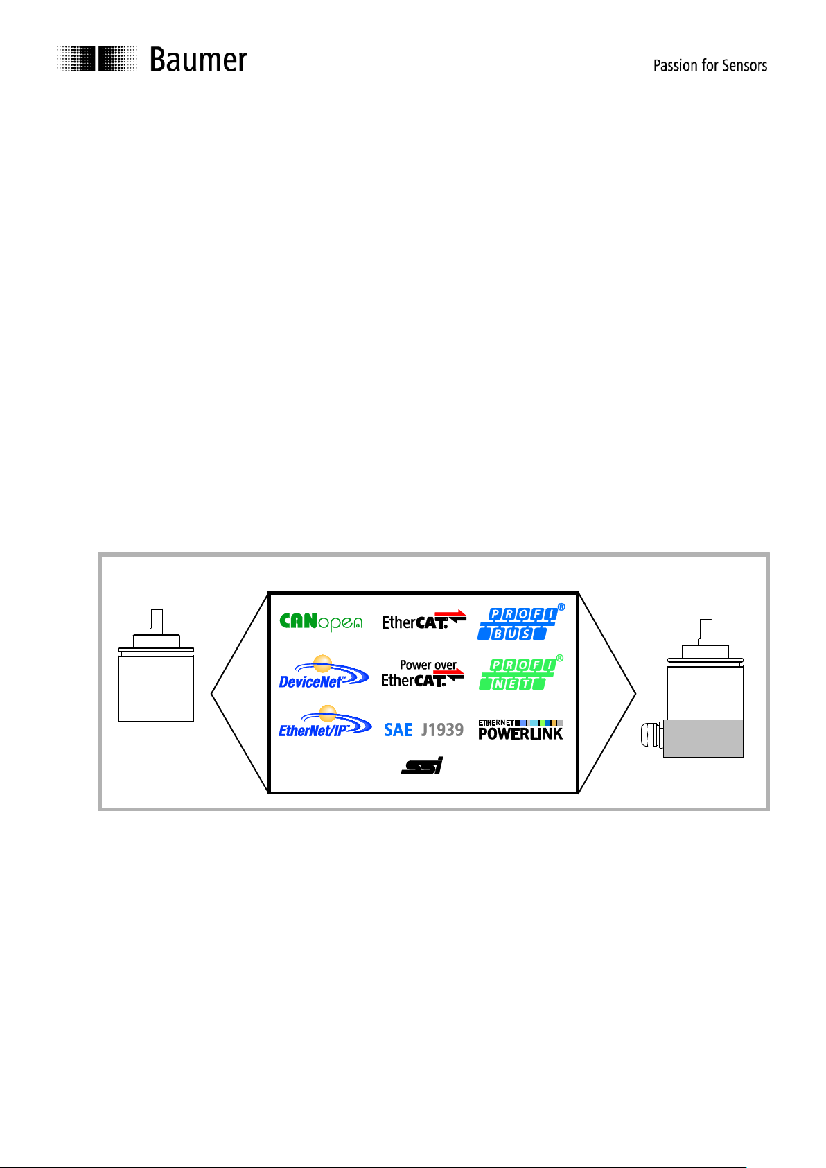
3. Product family
The product family architecture is modular. Depending on what is required from the encoder, the basic
encoder and bus covers can be combined at will with the selected bus system.
The basic encoders differ in terms of accuracy, ambient conditions and the utilized sensing principle.
Bus cover
The bus cover accommodates the field bus interface and the complete electronics for processing the
measured values. EtherNet/IP communication is performed via the specialized EtherNet/IP-ASIC ERTEC200
with integrated high-performance microcontroller ARM9.
Magres / magtivo
®
Utilizes a magnetic sensing principle and endures harsh industrial environments.
Procoder / multivo
®
Utilizes a photoelectric sensing principle and is the recommended product for precise applications.
Dignalizer / activo
®
/ multivoPlus
®
Utilizes a photoelectric sensing principle with integrated analog/digital signal conversion and is the product to
choose for ultra-precise sensing applications.
The bus covers differ by the respectively integrated bus interface.
Available bus interfaces: CANopen, DeviceNet, EtherCAT, Ethernet/IP, Profibus-DP, Profinet, Powerlink,
Power over EtherCAT, SAE J1939, SSI.
All encoders enable parameterization by bus interface.
Functional principle:
bus cover
complete encoder
basic encoder
Manual_ProfibusDPV2_BIDE_EN.docx 8/41 Baumer IVO GmbH & Co. KG
22.11.12 Villingen-Schwenningen, Germany
4. Commissioning
4.1. Mechanical mounting
Shaft encoders
Mount the encoder by help of the mounting holes and three screws (square flange: 4 screws) provided at
the encoder flange. Observe thread diameter and depth.
There is an alternative mounting option in any angular position by eccentric fixings, see under
accessories.
Connect drive shaft and encoder shaft by using an appropriate coupling. The shaft ends must not touch
each other. The coupling must compensate temperature and mechanical tolerances. Observe the
maximum permitted axial or radial shaft load. For appropriate couplings please refer to accessories.
Tighten the mounting screws firmly.
End shaft/hollow shaft encoders
Mounting by clamping ring
Prior to mounting the encoder open the clamping ring completely. Push encoder onto the drive shaft and
tighten the clamping ring firmly.
Adjusting element with rubber buffer
Push the encoder onto the drive shaft and insert the cylindrical pin into the adjusting element (provided by
customer) and the rubber buffer.
Adjusting angle
Push the encoder onto the drive shaft. Insert adjusting angle into the encoder’s rubber buffer and fasten
the adjusting angle at the contact surface.
Stud screw
Push the encoder onto the drive shaft and insert the stud screw provided by customer into the encoder’s
rubber buffer.
Spring coupling
Fasten the spring coupling at the mounting holes of the encoder housing using screws. Push the encoder
onto the drive shaft and mount the spring coupling to the contact surface.
4.2. Electrical connection
Ever store and transport the bus cover in the ESD bag only.
For electrical connection remove the bus cover as follows:
Release the fastening screws of the bus cover
Carefully loosen the bus cover and lift off in an axial direction
4.2.1. Cabling
EN 50170 specifies two types of PROFIBUS cable, type A and B. Type B is obsolete and should not be used
in new applications. With type A all transmission rates up to 12Mbit/s are possible. Common baud rate in
clock synchronous operation according to PROFIBUS-DPV2 is 12Mbit/s.
Properties
Data
Impedance in Ohm
135 to 165 at 3 to 20 MHz
Operating capacity (pF/m)
less than 30
Loop impedance (Ohm/km)
less than 110
Core diameter (mm)
greater than 0.64
Core cross section (mm)
greater than 0.34
Transmission speed depending on line distance
Baudrate in
kBaud
9,6
19,2
93,75
187,5
500
1500
3000
6000
12000
Line distance
in m
1200
1200
1200
1000
400
200
100
100
100
Manual_ProfibusDPV2_BIDE_EN.docx 9/41 Baumer IVO GmbH & Co. KG
22.11.12 Villingen-Schwenningen, Germany
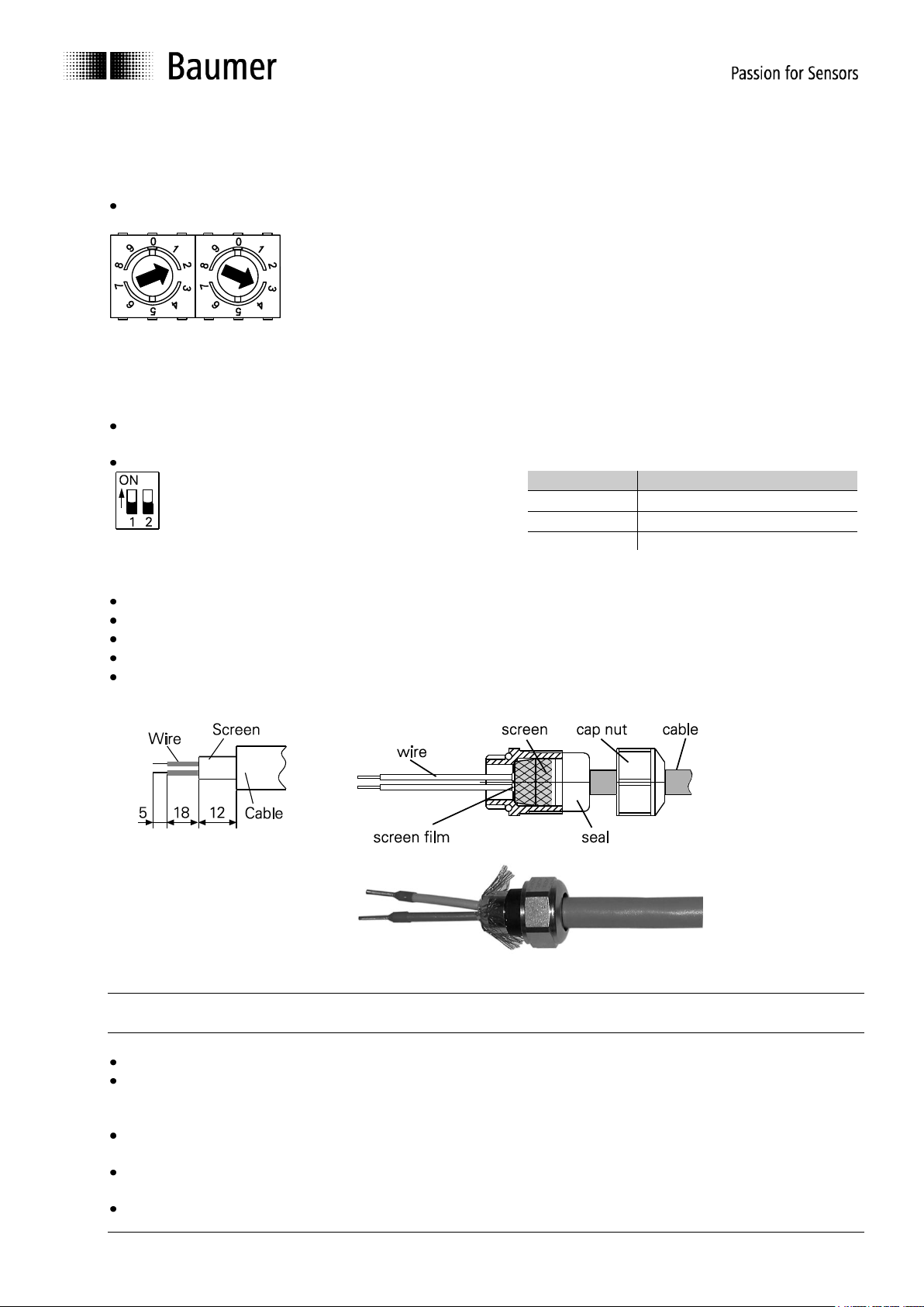
4.2.2. Setting the user address
The user address is set decimally using the two rotary switches provided in the bus cover.
The maximum number of users is 99.
Decimal setting of the user address by the help of rotary switches 1 and 2 (default setting 00).
Example: 23
4.2.3. Terminating resistor
If the encoder is the final device in the bus line it is mandatory to terminate the bus by resistors. The resistors
are integrated in the bus cover and connected by means of a two-pole DIP switch.
The internal terminating resistors must be switched to „ON“ in case of final user by help of the 2-pole DIP
switch (default setting OFF). The two switches must always be set in the same direction.
both ON = final user
both OFF = all other users
Clamp
Resistance
A to GND
390 Ohm
B to +5 V
390 Ohm
A to B
220 Ohm
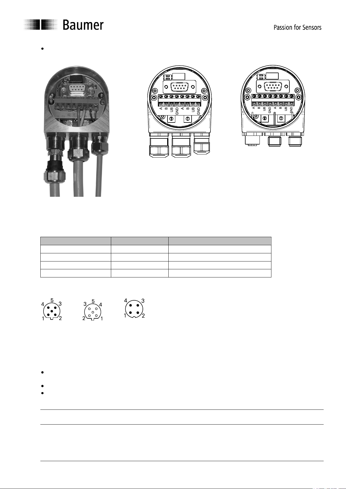
4.2.4. Connecting the bus cover
Release the cap nut of the cable gland
Push the cap nut and seal insert with contact sleeve onto the cable sheath.
Strip the cable heath and cores, shorten the shield film where it exists (see fig.)
Bend over the braided shield by approx. 90°.
Push the sealing insert with contact sleeve along as far as the braided shield. Insert the sealing insert
with contact sleeve and cable flush into the cable gland and tighten the cap nut.
Take care that by no means the voltage supply is assigned to bus terminals A/B, this could damage
electronics components in the bus cover.
Avoid stub lines, especially with bus clocks greater than 1.5Mbit/s
Clamps with the same designation are internally connected to each other and identical in functionality.
Maximum load on the internal clamped connections UB-UB and GND-GND is 1 A each.
Signals A and B are decoupled at 100 nH inductivity each.
For voltage supply use cable gland 3 only. For the bus lines, either cable gland 1 or 2 may be used.
Please observe the admissible cable cross-sections.
Guide the cores the shortest way from the cable gland to the terminal connector. Observe the admissible
core-cross sections, use ferrules with flexible cores.
Avoid any crossings of data lines and supply line.
Manual_ProfibusDPV2_BIDE_EN.docx 10/41 Baumer IVO GmbH & Co. KG
22.11.12 Villingen-Schwenningen, Germany
Seal up the unused cable gland using a sealing bolt (included in the delivery).
1 2 3
Cable gland
M12 connector
Terminal assignment
M12 connector
Clamp:
Significance
M12, 4 pins: Pin 1
UB
Supply voltage 10...30 VDC
M12, 4 pins: Pin 3
GND
Ground connection related to UB
M12, 5 pins: Pin 2
A
Negative serial data line
M12, 5 pins: Pin 4
B
Positive serial data line
M12 connector
for serial data lines
for voltage supply
male female
Clamps with the same designation are internally connected to each other and identical in function.
Maximum load on the internal clamped connections UB-UB and GND-GND is 1 A each.
Signals A and B are decoupled with an inductivity of 100 nH each.
Assembly of basic encoder and bus cover:
Carefully plug the bus cover onto the D-SUB connector of the basic encoder, then press it over the seal
taking care not to tilt it.
Tighten both fastening screws firmly in the same direction.
The bus cover must fully rest on the housing of the basic encoder and be firmly screwed on.
The encoder housing and braided shield of the connecting cable are only ideally connected if the bus cover is
resting fully on the basic encoder (positive locking).
Manual_ProfibusDPV2_BIDE_EN.docx 11/41 Baumer IVO GmbH & Co. KG
22.11.12 Villingen-Schwenningen, Germany
5. Projecting
All examples in the present manual relate to SIEMENS
®
controls and the corresponding projecting software
Step7
®
, since they are commonly used as PROFIBUS controls. Please proceed in a corresponding way with
other controls.
5.1. Importing the GSD file
To implement the DP-Slave in the projecting software first the attached GSD file must be imported. All
required modifications of basic settings are implemented by parameterization (see “Parameterization”). The
GSD file itself is not modified.
Step7
®
software is imported in the hardware window („Extras – install GSD-files“). Prior to the import
operation the actual hardware project must be closed („Station - close“). Now the encoder appears at right in
the hardware catalogue under „PROFIBUS-DP“ – „More field devices“ – „Encoder“ – (xx corresponding to
the encoder type).
5.2. Encoder bus implementation
Use the mouse to drag text „GxxMW_H IsoM“ from the right out of the hardware catalogue to the bus bar. A
window pops up to enter the PROFIBUS node ID that must correspond to the settings of the BCD switch in
the bus cover. All other entries may remain unchanged. Close the entry by OK.
Use the mouse again to drag encoder module „telegram 81“ from the right out of the hardware catalogue to
plug-in position 1 of the module window at left below in the hardware window. Do not utilize the universal
module, this is not considered.
5.3. Assigning the user address
If not already done in a previous step or if required at a later date you may alter the PROFIBUS node ID of
the encoder. Upon a double click the window „Properties – DP-Slave“ pops up. Click on „PROFIBUS…“ and
enter the required node ID here. The node ID must correspond to the settings of the BCD switch in the bus
cover.
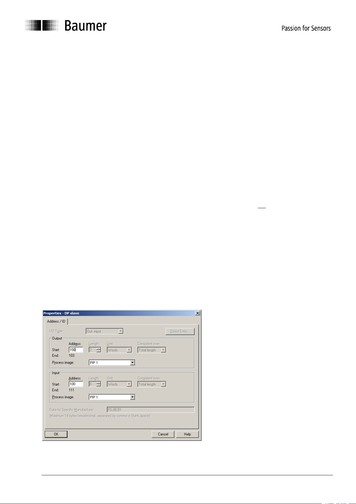
5.4. Assigning addresses for input and output data
Later access to encoder input and output data via master software requires assigning E/A addresses to the
input and output data. Click on the encoder icon on the bus bar HW config of Step7 to select the encoder.
Then double-click on module “telegram 81” (plug-in position 1) at left below. The window “Properties - DP-
slave” with tab “Address/ID” pops up (see screenshot).
Enter the respective initial addresses. It is admissible to use Identical or overlapping addresses for output and
input.
Manual_ProfibusDPV2_BIDE_EN.docx 12/41 Baumer IVO GmbH & Co. KG
22.11.12 Villingen-Schwenningen, Germany
E/A fields require defining partial process images in clock-synchronous operation, in the example it is TPA1.
Take care that the selected partial process image comprises the initial address. If not it will result in an error
signal when interpreting the project.
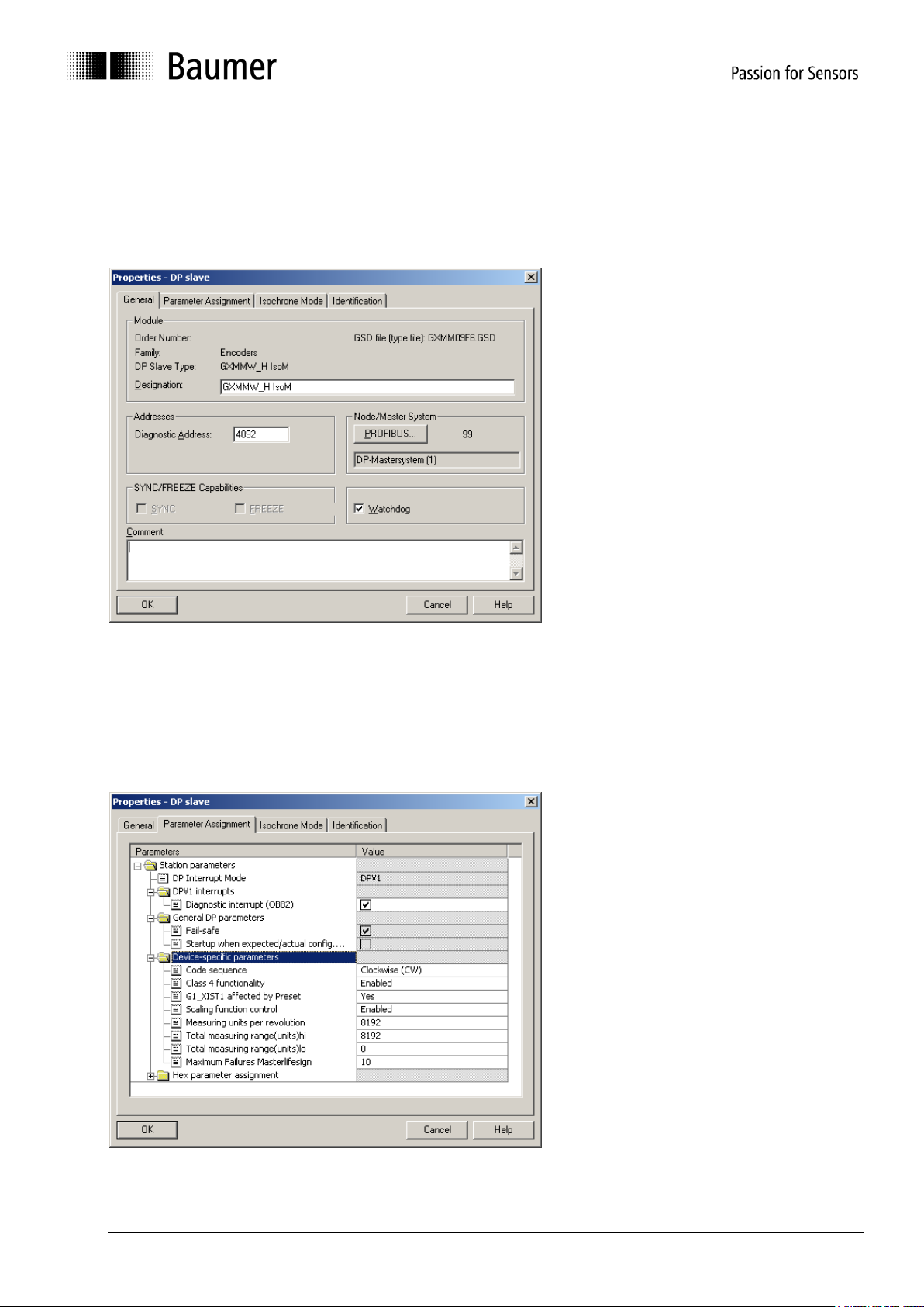
5.5. Parameterization
Upon double-click on the encoder icon at the bus bar, the window „Properties-DP-Slave“ pops up, showing
the tabs “General”, “Parameter Assignment” and “Clock synchronisation”.
5.5.1. General
System parameters under tab „General“ may usually be adopted without modifications.
If required, encoder name, diagnosis address and node ID under button „Profibus…” may be altered. Further
here is the option to deactivate the encoder’s response monitoring.
5.5.2. Parameter assignment

Manual_ProfibusDPV2_BIDE_EN.docx 13/41 Baumer IVO GmbH & Co. KG
22.11.12 Villingen-Schwenningen, Germany
Device-specific parameters
Code sequence
Behaviour of the position data in relation to the sense of rotation of the encoder shaft when looking at
flange.
CW („clockwise“) = Ascending values with clockwise rotation
CCW („counter-clockwise“) = Ascending values with counter-clockwise rotation
Class 4 functionality
If active („enabled“), the encoder operates as a Class 4 Device of the encoder profile.
If not active ( „disabled), the encoder operates as a Class 3 Device of the encoder profile.
Here setting a preset is disabled.
G1_XIST1 affected by preset
If active (“Yes”), setting a preset will affect both the left-aligned position value G1_XIST1 and the
right-aligned position value G1_XIST2.
If not active (“No”), the left-aligned position value G1_XIST1 is not added an offset that is internally
calculated upon setting a preset. In this case, both position values G1_XIST1 and G1_XIST2 may be
different!
Scaling function control
If active (“enabled”), resolution („steps per revolution“, “measuring units per revolution”) and the total
measuring range can be parameterized at will within the admissible limits.
If not active (“disabled”), the previous encoder settings for resolution and total measuring range will
remain, i.e. the maximum limits. Any try to enter deviating parameters will result in a parameterization
error signal.
Measuring units per revolution
Parameterization of the required resolution („steps per revolution“, „measuring units per revolution“).
Admissible values range from 1 to the maximum encoder resolution. Usually the limits are indicated
in the parameterization software.
multivoPlus encoders require a 32 bit value here to get two input fields, i.e. „measuring units per
revolution (hi)“ and „(lo)“. Ho to split the 32 bit value into two 16 bit values please see under 8.1.4.
A re-parameterization may clear the previous offset value (see “note” under 6.6. Preset function).
Total measuring range (units)
Parameterization of the required total measuring range, „TMR“.
Singleturn encoders require here the same parameter as for the resolution (“Measuring units per
revolution“).
Admissible values range from 2 to the product of programmed resolution multiplied by maximum
number of revolutions. The maximum limit of the parameterization software is only applicable if the
resolution is also the maximum.
All multiturn encoders and multivoPlus singleturn encoders need a 32 bit value here to get two input
fields, „Total measuring range (units) hi“ and „lo“. How to split up the 32 bit value into two 16 bit
values please see under 8.1.4.
Any alteration of the total measuring range clears the previous offset value (see “note” under 6.6
Preset Function)
 Loading...