

Page 1

Manual
Absolute Encoder with hollow shaft and Interbus
Version from 1.10
Baumer IVO GmbH & Co. KG
Dauchinger Strasse 58-62
DE-78056 Villingen-Schwenningen
Phone +49 (0)7720 942-0
Fax +49 (0)7720 942-900 05.11 · 174.02.057/2
info.de@baumerivo.com Subject to technical and design modifications.
www.baumer.com Errors and omissions excepted.
Page 2

Contents
1 Introduction 3
1.1 Scope of delivery 3
1.2 Product assignment 3
2 Illustration of Encoder Data within Master 4
2.1 Position of the Encoder Data within the 2-word Addresses 4
2.2 Significance of the OUT Data (Data from the Master to the Encoder) 4
2.3 Significance of the IN Data (Data from Encoder to Master) 4
3 Possible Modes of Operation 5
4 Behavior of Encoder after Power ON 5
5 Parameterization 5
6 Examples 8
7 Disturbance messages 10
8 Contact description 11
8.1 Contact description for C-plug 11
8.2 Pin assignment for C-plug 11
9 Technical data 12
9.1 Part number 12
9.2 Accessories 12
9.3 Dimensions 13
Manual_GXP6H_EN.doc 2/13 Baumer IVO GmbH & Co. KG
04.05.11 Villingen-Schwenningen, Germany
Page 3

Disclaimer of liability
The present manual was compiled with utmost care, errors and omissions reserved. For this reason
Baumer IVO GmbH & Co. KG rejects any liability for the information compiled in the present manual.
Baumer IVO nor the author will accept any liability for direct or indirect damages resulting from the use of the
present information.
At any time we should be pleased receiving your comments and proposals for further improvement of the
present document.
1 Introduction
1.1 Scope of delivery
Please check the delivery upon completeness prior to commissioning.
Depending on encoder configuration and part number delivery is including:
• Encoder
• Manual available as download in the Internet
1.2 Product assignment
Hollow shaft encoder
Product Product family
GXP6H Multiturn
Manual_GXP6H_EN.doc 3/13 Baumer IVO GmbH & Co. KG
04.05.11 Villingen-Schwenningen, Germany
Page 4
2 Illustration of Encoder Data within Master
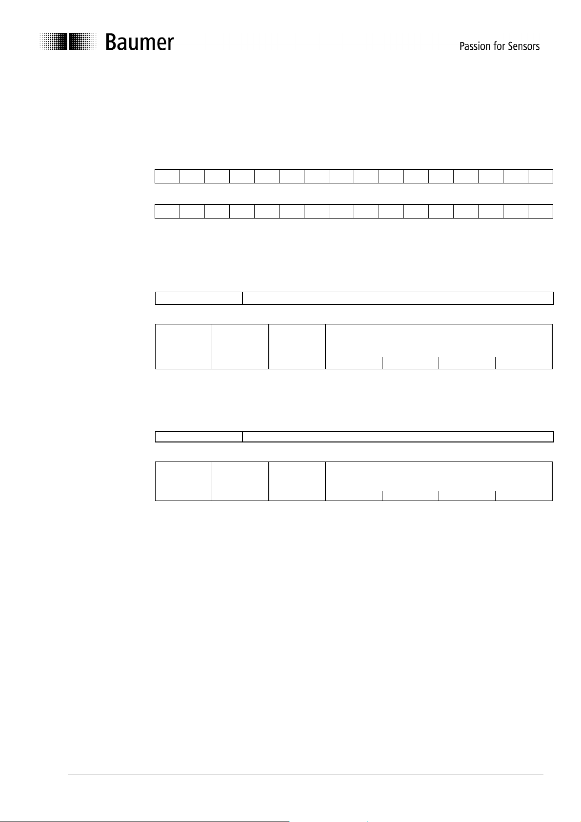
2.1 Position of the Encoder Data within the 2-word Addresses
Word 0 (Byte 0,1) 231 230 229 228 227 226 225 224 223 222 221 220 219 218 217 216
MSB LSB
Word 1 (Byte 2,3) 215 214 213 212 211 210 29 28 27 26 25 24 23 22 21 20
MSB LSB
2.2 Significance of the OUT Data (Data from the Master to the Encoder)
2.3 Significance of the IN Data (Data from Encoder to Master)
The IN as well as OUT data of the encoder are assigned 2-word addresses within the master (control). The absolute
position of these word addresses depends on the position of the encoder on the Interbus ring.
Please find below the value of the encoder data relating to the relative word address.
D31
OUT Data:
Control
word:
D31
IN Data: Status word Actual position value or disturbance number
Status
word:
D31 D30 D29 D28 D27 D26 D25
Control word Parameter
Enable
operation
D31 D30 D29 D28 D27 D26 D25
Actual
position value
not valid
D25
Set zero
offset
D25
Parameterizat
ion
D24 D0
Specific to
manufacturer
D24
D0
Specific to
manufacturer
Disturbance number in case of error
otherwise 0000
Parameter No.
Manual_GXP6H_EN.doc 4/13 Baumer IVO GmbH & Co. KG
04.05.11 Villingen-Schwenningen, Germany
Page 5

3 Possible Modes of Operation
Normal Operation
Control
word:
Actual
position value
Set zero
offset
Specific to
manufacturer
Parameter No.
not valid
D31 D30 D29 D28 D27 D26 D25
Operation 0 0 0 0
Parameterization
Control
word:
Actual
position value
Set zero
offset
Specific to
manufacturer
Parameter No.
not valid
D31 D30 D29 D28 D27 D26 D25
Parameteri
0 0 X 1...7 or 15
zation
Enable
0>1 0 X 0
operation
4 Behavior of Encoder after Power ON
After power has been turned on, the following steps will take place during the initialization phase of encoder:
Test of battery tension
Switch to parameter mode
Loading of the most recent parameter data from EEPROM
Checking of parameter data as to their validity
After initialization the encoder switches to the OPERATION state and emits the current position value. In case of an
error (battery tension too low or parameter loss), however, the encoder commutes to the ERROR state.
5 Parameterization
The parameters of a profile K3 encoder can be transferred via the bits 0 to 24 of the process data channel to the
encoder. To this effect, the encoder has to be set to the parameterization state by a allotting parameter number not
equal to zero to the bits 9 to 12 of the control word (bit 25 to 28 of the process data channel).
Parameter No.
D28 D25
0 0 0 1 Resolution: Sub-parameter Steps 1..33554431 8192
0 0 1 0 Resolution: Sub-parameter Revolutions 1..4096 1
0 0 1 1 Coding of actual position value 1..6 3
0 1 0 0 Preset value 0..33554431 0
0 1 0 1 Zero offset 0..33554431 0
0 1 1 0 Offset 0..33554431 0
0 1 1 1 Reset of encoder - 1 1 1 1 Measuring range 1..4096 4096
Resolution
The resolution of the encoder is adjusted via the sub-parameters „Steps“ and „Revolutions“ and the resolution is
calculated according to the formula: Resolution = Steps / Revolutions.
The parameters Steps = 1000 and Revolutions = 3 result in a resolution of 333.333.. steps/revolution.
Function Value range
maximum
Factory
setting
Manual_GXP6H_EN.doc 5/13 Baumer IVO GmbH & Co. KG
04.05.11 Villingen-Schwenningen, Germany
Page 6

Coding of Actual position value
The parameter defines the coding of the actual value of the position allotted during OPERATION state.
Dual code with plus/minus sign (Integer)
Ascending code for sense of rotation 'right' (clockwise) with view on shaft
Dual code with plus/minus sign (Integer)
Ascending code for sense of rotation 'left' (counter-clockwise) with view on shaft
Dual code without plus/minus sign (Unsigned)
Ascending code for sense of rotation 'right' (clockwise) with view on shaft
Dual code without plus/minus sign (Unsigned)
Ascending code for sense of rotation 'left' (counter-clockwise) with view on shaft
Gray code without plus/minus sign
Ascending code for sense of rotation 'right' (clockwise) with view on shaft
Gray code without plus/minus sign
Ascending code for sense of rotation 'left' (counter-clockwise) with view on shaft
Preset Value
The value of the parameter 'Preset Value’ is used to find out the zero offset.
If the control command Set Zero Offset (control bit D30) is triggered by the master, the parameter Zero Offset is set
within the encoder to the value resulting from the following formula:
NPV = PW - API
The abbreviations stand for:
NPV Zero offset
PW Preset value
API Absolute actual value of position
Remark:
The calculated NPV value is not stored in E²Prom if activated by control bit D30. Due to the limited writing cycles of the
E²Prom, this value gets lost in case of power loss. However, when setting parameters, for example preset, also the
current NPV value is stored in E²Prom.
Manual_GXP6H_EN.doc 6/13 Baumer IVO GmbH & Co. KG
04.05.11 Villingen-Schwenningen, Germany
Page 7

Zero Offset
The parameter Zero Offset refers to the difference between the zero point of the installation and the zero point of the
encoder. The actual position value is calculated according to the following formula:
PI = API + NPV
The abbreviations stand for:
PI Actual position value (is transferred)
API Absolute actual value of position
NPV Zero set off
Offset
The parameter 'Offset' is an additional possibility to offset the actual position value.
The actual position value is calculated according to the following formula:
PI = API + NPV + O
The abbreviations stand for:
PI Actual position value (is transferred)
API Absolute actual value of position
NPV Zero offset
O Offset
Resetting Encoder
When the parameter 'Reset Encoder' is transmitted to the encoder, all parameters are set back to their factory setting.
Measuring Range
It is possible to adjust the entire range of the position value via the parameter 'Measuring Range’. The unit for the
measuring range is the number of revolutions. If, for example, a resolution of 200 steps per revolution and a
measuring range of 5 revolutions are chosen, there ensues a total range of:
Total range = Resolution * Measuring range = 200 * 5 = 1000 steps
The total range of the position value thus stretches in the process data output without plus/minus signs from 0..999
and in the process data output with plus/minus signs from -500..499.
Manual_GXP6H_EN.doc 7/13 Baumer IVO GmbH & Co. KG
04.05.11 Villingen-Schwenningen, Germany
Page 8

6 Examples
Example 1: Example for a parameter transfer
Host to Encoder Encoder to Host Remarks
Control word Status word
D31 D25-
D28
D0-D24 D30-
D31
D25-
D28
D0 D24
1 0 0 x 0 0 0 Actual
value
2 0 P. No. Parameter 0 0 0 Actual
value
3 0 P. No. Parameter 0 0 0 Actual
value
4 0 P. No. Parameter 1 1 1) Para-
meter
5 0 P. No. Parameter 1 1 1) Para-
meter
6 0 P. No. Parameter 1 1 P. No. Para-
meter
7 1 0 0 1 1 P. No. Para-
meter
8 1 0 0 0 0 0 Actual
value
9 0 0 0 0 0 0 Actual
value
Normal operation
Host sends parameter to encoder,
encoder shows no reaction yet
Host continues to wait for encoder
confirmation
Encoder has taken over parameter and
starts processing
Parameter processing within encoder is
still running
Parameter processing has been finished,
encoder remains in "Parameterization"
state
Device control command "Enable
operation " from Host to encoder. Encoder
shows no reaction yet
Encoder is again in "Operation" state
Back again to normal operation state of
both participants
1): It must be ensured not to transfer the same parameter number as already confirmed by the encoder when
transmitting a parameter. It is not allowed to repeat the transfer of the same parameter without leaving the
"Parameterization" state.
The parameter number must be consistent.
When transferring several parameters, steps 4 to 6 must be repeated.
It must be ensured when transmitting a parameter that the parameter number is not allotted by the
parameter.
If parameters are transferred that are not valid or do not harmonize, the encoder will turn to the "Disturbance"
state when trying to enable operation.
Manual_GXP6H_EN.doc 8/13 Baumer IVO GmbH & Co. KG
04.05.11 Villingen-Schwenningen, Germany
Page 9

Example 2: Procedure when transferring non-harmonizing parameters
Host to Encoder Encoder to Host Remarks
Control word Status word
D31 D25-
D28
1 0 0 x 0 0 1) Actual
D0-D24 D30-
D31
D25-
D28
D0 D24
Normal operation
value
2 0 2 20 000 0 0 1) Actual
value
3 0 2 20 000 0 0 1) Actual
value
Host sends value in order to program
resolution (number of revolutions)
Host continues to wait for encoder
confirmation
4 0 2 20 000 1 1 1) 20 000 Encoder has taken over parameter and
starts processing
5 0 2 20 000 1 1 1) 20 000 Parameter processing within encoder is
still running
6 0 2 20 000 1 1 2 20 000 Parameter processing has been
finished, encoder remains in
"Parameterization" state
7 0 3 1 1 1 2 20 000 Host sends value to program coding of
actual position value
8 0 3 1 1 1 2 20 000 Host continues to wait for encoder
confirmation
9 0 3 1 1 1 2 1 Encoder has accepted parameter and
starts processing
10 0 3 1 1 1 3 1 Parameter processing has been
finished, encoder remains in
"Parameterization" state
11 1 0 0 1 1 3 1 Device control command "Enable
operation " from Host to encoder.
Encoder shows no reaction yet
12 1 0 0 0 1 1 0 Encoder switches to "Disturbance"
state, the disturbance code is "1". The
actual position value is not allotted on
the process data channel.
Here a try has been made to set the resolution of the encoder to 20 000 revolutions. The encoder reacts to
this inadmissible parameter setting by switching to the "Disturbance" state and by emitting the disturbance
code "1".
Manual_GXP6H_EN.doc 9/13 Baumer IVO GmbH & Co. KG
04.05.11 Villingen-Schwenningen, Germany
Page 10

7 Disturbance messages
If there occurred an error when turning power on or during parameterization, the encoder switches to the
DISTURBANCE state after the user has passed the device control command ENABLE OPERATION and allots a
disturbance number to the bits D25-D28 of the status word. If an error occurs within the encoder during the
OPERATION state (e.g.: disturbance number 15), the encoder automatically switches to the DISTURBANCE state.
Disturbance No.
D28 D25
0 0 0 0 No disturbance
0 0 0 1 Inadmissible parameter from Master
0 0 1 0 Unknown parameter number
0 0 1 1 Parameter loss
1 1 0 1 Error when storing into EEPROM
1 1 1 0 Warning: Battery tension too low
1 1 1 1 Faulty value of encoder disk
Status word at disturbance:
Status
word:
Disturbanc
e
Sign a disturbance:
Status
word:
Enable
operation
Significance
Actual posit.
vakue not
valid
D31 D30 D29 D28 D27 D26 D25
1 0 X 1...3 or 13...15
Enable
operation
D31 D30 D29 D28 D27 D26 D25
0>1
Parameter-
Set zero
offset
0 X 0
specific to
manu-factorer
izat
ion
specific to
manu-factorer
Disturbance no.
Disturbance no.
Manual_GXP6H_EN.doc 10/13 Baumer IVO GmbH & Co. KG
04.05.11 Villingen-Schwenningen, Germany
Page 11

8 Contact description
8.1 Contact description for C-plug
D01, D01 Incoming long-distance bus (A1) galvanically
DI1, DI1 separated from remaining encoder electr.
GNDI Galvanically separated reference mass for incoming long-distance bus (A1).
Models without electrical isolation combined with GND.
UB Contacts for encoder supply incorporated
GNDB within the bus (A1), UB = 10...30 VDC. Current load max. 700 mA
D02, D02 Relaying long-distance bus (W1)
DI2, DI2
GND Reference mass for relaying long-distance bus (W1)
UB Contacts for encoder supply within bus
GNDB (W1), UB = 10 ... 30 VDC. Connected internally with UB/GND B from A1
PE Screening combined with encoder housing
RBST Recognition of further bus users
Open contact: Last user
Contact to GND: User X
8.2 Pin assignment for C-plug
8
1
2
7
9
3
6
4
5
8
1
7
9
2
3
6
5
4
Incoming interface Outgoing interface
(pin) (socket)
Pin Assignment Pin Assignment
1 D01 1 D02
2 D01 2 D02
3 DI1 3 DI2
4 DI1 4 DI2
5 GNDI 5 GND
6 PE 6 PE
7 UB 7 UB
8 GNDB 8 GNDB
9 – 9 RBST
Manual_GXP6H_EN.doc 11/13 Baumer IVO GmbH & Co. KG
04.05.11 Villingen-Schwenningen, Germany
Page 12

9 Technical data
9.1 Part number
Order no. Hollow shaft
0 Ø 14 mm, grub screw
1 Ø 12 mm, grub screw
2 Ø 14 mm, clamping ring
Voltage
10 10 ... 30 VDC with electr. isolation
Connection
A1 2 x 9 pins with C-plug, radial
Software
01 Program K3
GXP6H.
9.2 Accessories
Order no.
Z 153.B01 Connector socket, 9 pins
Z 153.S01 Connector pin, 9 pins
Manual_GXP6H_EN.doc 12/13 Baumer IVO GmbH & Co. KG
04.05.11 Villingen-Schwenningen, Germany
Page 13

9.3 Dimensions
incoming
interface
(pin)
outgoing
interface
(socket)
washer
Shaft
packing
washer
Felt
ø20
ø14H7
13.3
4
2.5
3H11
Grub screw
with hex
socket-head
screw
M3x4 DIN913
stainless
Nose
56.5
13.3
ø30
Model
with
clamping
ring
55
150
ø4fg6
15
120°
75
38
3.5
76
Manual_GXP6H_EN.doc 13/13 Baumer IVO GmbH & Co. KG
04.05.11 Villingen-Schwenningen, Germany
 Loading...