

Page 1

Manual
Inclination sensor with Profibus-DP interface
Firmware Version 1.00 and up
Baumer IVO GmbH & Co. KG
Dauchinger Strasse 58-62
DE-78056 Villingen-Schwenningen
Phone +49 (0)7720 942-0
Fax +49 (0)7720 942-900 05.11 · 174.02.052/3
info.de@baumerivo.com Subject to modification in technic and design.
www.baumer.com Errors and omissions excepted.
Page 2

Contents
Page
1. Introduction 3
1.1. Scope of delivery 3
1.2. Product assignment 3
2. Safety and operating instructions 4
3. Profibus-DP 5
4. Operating parameters of the inclination sensor 6
5. Data exchange between Profibus-DP devices 7
5.1. Telegram structure 7
5.2. Initialization, restarting and user data communication 7
6. Parameterization and configuration 8
6.1. Parameterization 8
6.2. Configuration 10
6.3. Significance of diagnostic data Slave_Diag 11
6.4. User data 12
6.5. Inclination angle readout 12
6.6. Preset function 14
6.7. Offset function (not possible for the 360° sensor) 14
7. Terminal assignment and commissioning 16
7.1. Mechanical mounting 16
7.2. Electrical connection 17
7.2.1. Setting the user address (Node ID) 17
7.2.2. Terminating resistor 17
7.2.3. Electrical connection of the inclination sensor 18
7.2.4. View inside the inclination sensor 18
7.2.5. Terminal assignment 19
7.2.6. Status indicating elements (LEDs) 19
7.2.7. Profibus cable 19
Manual_GNAMG_Profibus_EN.doc 2/19 Baumer IVO GmbH & Co. KG
04.05.11 Villingen-Schwenningen, Germany
Page 3
Disclaimer of liability
The present manual was compiled with utmost care, errors and omissions reserved. For this reason
Baumer IVO GmbH & Co. KG rejects any liability for the information compiled in the present manual.
Baumer IVO nor the author will accept any liability for direct or indirect damages resulting from the use of the
present information.
At any time we should be pleased receiving your comments and proposals for further improvement of the
present document.
1. Introduction
1.1. Scope of delivery
Please check the delivery upon completeness prior to commissioning.
Depending on encoder configuration and part number delivery is including:
• Encoder
• CD with describing file and manual (also available as download in the Internet)
1.2. Product assignment
Product GSD file Product family
GNAMG.x213Pxx GNAMG_15.gsd Inclination sensor
GNAMG.x223Pxx GNAMG_30.gsd Inclination sensor
GNAMG.x233Pxx GNAMG_60.gsd Inclination sensor
GNAMG.x153Pxx GNAMG360.gsd Inclination sensor
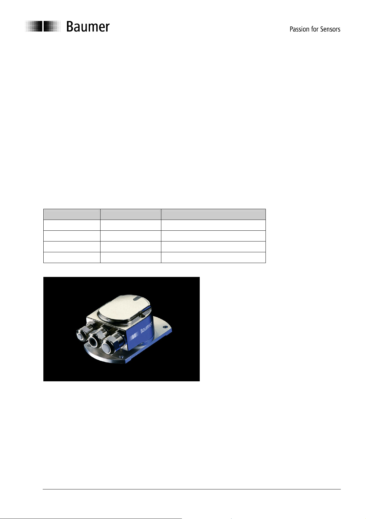
Fig.: Inclination sensor on base plate
Manual_GNAMG_Profibus_EN.doc 3/19 Baumer IVO GmbH & Co. KG
04.05.11 Villingen-Schwenningen, Germany
Page 4

2. Safety and operating instructions
Supplementary information
• This manual is intended as a supplement to already existing documentation (e.g. catalogue, product
information and mounting instruction).
• The manual must be carefully read prior to initial commissioning of the equipment.
Intended purpose of the equipment
• The inclination sensor is a precision sensing device. It is expressly used to determine inclination
angles and to prepare and supply measured values in the form of electrical output signals for the
downstream device. The inclination sensor must not be used for any other purpose.
Commissioning
• The inclination sensor may only be installed and mounted by qualified experts.
• Observe the operating instructions of the machine manufacturer.
Safety precautions
• Prior to commissioning the equipment, check all electrical connections.
• If installation, electrical connection or any other work performed at the inclination sensor or at the
equipment is not correctly executed, this can result in malfunction or failure of the inclination sensor.
• Steps must be taken to exclude any risk of personal injury, damage to operating or corporate
equipment as a result of an inclination sensor malfunction by providing suitable safety precautions.
• The inclination sensor must not be operated outside the limits (see detailed product information).
Failure to comply with the safety instructions can result in malfunctions, personal injury or damage to
property!
Transport and storage
• Only ever transport or store the inclination sensor in its original packaging.
• Never drop the inclination sensor or expose it to major shocks.
Mounting
• Avoid impacts or shocks on the housing.
• The bus cover must fully rest against the base plate when mounted. Any tolerances in assembling the
bus cover onto the base plate may have a negative impact on the absolute inclination angle.
Electrical commissioning
• Do not proceed any electrical modifications at the inclination sensor.
• Do not carry out any wiring work when the inclination sensor is live.
• Never plug or unplug the electrical connection when the inclination sensor is live.
• Make sure that the entire system is installed in line with EMC requirements. Ambient installations and
cabling affect the electromagnetic compatibility of the inclination sensor. Install inclination sensor and
supply cables separately or far away from cables with high interference emissions (frequency
converters, contactors, etc).
• Arrange for separate power supply of the inclination sensor where working with consumers that have
high interference emissions.
• Completely shield the inclination sensor housing and connecting cable.
• Connect the inclination sensor to protective earth (PE) using shielded cable. The braided shield must
be connected to the cable gland or plug. Ideally, aim at bilateral connection to protective earth (PE),
the housing via the mechanical assembly, the cable shield via the downstream devices. In case of
earth loop problems, earth on one side only as a minimum requirement.
Failure to observe these instructions can result in malfunctions, personal injury or damage to property!
Manual_GNAMG_Profibus_EN.doc 4/19 Baumer IVO GmbH & Co. KG
04.05.11 Villingen-Schwenningen, Germany
Page 5

3. Profibus-DP
General information
Bus systems are connecting configurations that generate communication between several components.
Profibus DP is a manufacturer-independent open communication system for applications in the fields of
production, process and industrial building automation. It is broken down into three variants:
• Profibus FMS for data communication between controls on the production and process management
level.
• Profibus PA for process engineering applications.
• Profibus DP for fast data exchange between control units and decentralized peripherals in process
automation.
The Profibus system comprises the following device types:
• DP master class 1 (DPM1) is a control for cyclic information exchange with a DP Slave.
• DP master class 2 (DPM2) is a programming or project processing device or operating equipment.
• DP Slave is a peripheral that reads in output data and passes input data onward to a PLC.
The Profibus system is broken down into a monomaster system and a multimaster system by the number
of active masters during the operating phase.
• In a monomaster system, only one master class 1 and the DP slaves are active in the bus.
• In a multimaster system, several masters and the DP slaves are active in the bus. The masters can
optionally either belong to class 1 or class 2.
Profibus-DP is characterized by the following properties:
• Short response times (1 ms with 32 users und 12 MBaud)
• Reliable transmission procedure (Hamming distance 4)
• Availability of a wide range of standardized system components
• Good diagnostic capability
• Simply handling and facility for upgrading
• User-oriented bus system
• Open system
Profibus-DP ist standardized by EN 50170 Vol. 2. This standard defines the communication and user
profiles. User profile for the interface converter is profile 1.1. The user profile is differentiated in relation to
the number of supported functions according device class 1 and 2. Device class 2 provides a greater
number and comprises all the functions of class 1. Parameterization and preset functions are supported
only by class 2. The device supports both class 1 and 2.
GSD file
The device master data file (GSD-file) is a descriptive file describing all required operating data of the
Profibus user. The data itself are also filed in the ROM of the user. The data can be subdivided into two
sections:
• General definitions contain information such as the manufacturer’s name, product name, ident number,
Profibus-specific parameters and baud rates.
• Application-related configurations include information relating to configuration options, parameters,
parameter descriptions, hardware and software status and diagnostic capabilities.
Format and contents are defined in standard EN 50170.
The GSD file’s ident number is 059B for all described products. The GSD file is prior condition for
parameterization and configuration of the inclination sensor by a configuration tool.
Manual_GNAMG_Profibus_EN.doc 5/19 Baumer IVO GmbH & Co. KG
04.05.11 Villingen-Schwenningen, Germany
Page 6

4. Operating parameters of the inclination sensor
Explanations on operating parameters
Parameter Significance
Resolution Resolution of the inclination angle
0.001° = 0001h (not possible for the 360° sensor)
0.01° = 000Ah (not possible for the 360° sensor)
0.1° = 0064h
1.0° = 03E8h
Preset value X-axis
(Slope lateral
preset value)
Preset value Y-axis
(Slope long preset
value)
Offset X-axis
(Slope lateral
offset)
Offset-value
(Slope long offset)
The actual inclination value of the X-axis is set to a requested value
The actual inclination value of the Y-axis is set to a requested value
(not possible for the 360° sensor))
The here entered value is directly added to the actual inclination value of the Xaxis (not possible for the 360° sensor)
The here entered value is directly added to the actual inclination value of the Yaxis (not possible for the 360° sensor)
Manual_GNAMG_Profibus_EN.doc 6/19 Baumer IVO GmbH & Co. KG
04.05.11 Villingen-Schwenningen, Germany
Page 7

5. Data exchange between Profibus-DP devices
5.1. Telegram structure
The diagram shows the telegram structure.
Telegram structure
Request telegram
Footer info Output data Header info
DP Master
Response telegram
Header info Input data Footer info
5.2. Initialization, restarting and user data communication
Prior to user data exchange between master und slave every slave is re-initialized. The master transmits
parameterization and configuration data to the slave. Only when parameterization and configuration data
are congruent to the data stored in the slave the user data exchange is proceeded in the following way:
Diagnostic request from master
The master transmits a Slave Diagnosis Request (Slave_Diag), the Slave replies by a Slave Diagnosis
Response.
The master utilizes this data to check whether the slave exists in the bus and is ready for parameterization
and configuration.
Slave parameterization
The master transmits a Slave Parameter Request (Set_Prm).
By the parameterization data the slave receives information about current bus parameters, monitoring
times and slave-specific parameters. During the project processing phase the parameters are partially
adopted directly or indirectly from the GSD file. The slave compares this parameterization with its own
stored data.
Slave configuration
The master transmits a Check Configuration Request (Chk_Cfg).
The master informs the slave of amount (number of data bytes) and structure (data consistency) of the
input and output ranges to be exchanged. The slave compares this configuration with its own
configuration.
Diagnosis request prior to data exchange
The master transmits another Slave Diagnosis Request (Slave_Diag), the slave replies by a Slave
Diagnosis Response.
Now the master is checking whether parameterization and configuration are congruent with the data
stored in the slave. If the data requested by the master are admissible and no error has occurred, the
slave is signalising its readiness for user data transfer by help of the diagnosis data.
Data_Exchange
The slave will only respond to the master it was parameterized and configured by.
The master transmits a user data request (Data_Exchange), the slave replies by a user data response
informing the master whether current diagnostic results are available. The slave will not transmit the true
diagnostic and status information until a diagnostic telegram by the master is received.
DP Slave
Manual_GNAMG_Profibus_EN.doc 7/19 Baumer IVO GmbH & Co. KG
04.05.11 Villingen-Schwenningen, Germany
Page 8

6. Parameterization and configuration
6.1. Parameterization
Parameterization refers to transfer of information required by the slave for process data exchange. The
information comprises Profibus-specific data (octet 1 to 6) as well as user-specific information. Userspecific information can be entered via an input window during the project processing phase.
The data received from master are compared by the slave with the data it has stored. However, the slave
will only inform the master of the result in the diagnosis request after configuration.
Parameter description for the parameterization function (Set_Prm)
Parameter Octet Nr. Significance
Definition of profibus-specific data
Station status 1
Response monitoring time 2 to 3
Min. Station Delay
Responder (tsdr)
Ident_No. 5 to 6
Group_Ident_No. 7 Profibus-specific data
Operating parameter 8 Profibus-specific data
Parameters of the
inclination sensor
Resolution 10 Parameter location for four optional resolutions
4
9
• Sync mode/freeze mode active
• Response monitoring active
• Master assigned
Recognition of master failure, master must respond
within this time
Minimum time the slave has to wait until it is allowed
to respond to a master’s request
Device identifier, unique for each device type,
defined and reserved by the PNO
Definition of application-specific data
• Inversion of the inclination angles of the axis
• Scaling function
• Standard diagnosis/ extended diagnosis
• Resolution
Manual_GNAMG_Profibus_EN.doc 8/19 Baumer IVO GmbH & Co. KG
04.05.11 Villingen-Schwenningen, Germany
Page 9

Parameter values of parameterization function (Set_Prm)
Parameter
Station status
Response monitoring
time
Minimum Station Delay
Responder
Ident No.
Group Ident No.
Operating parameter
Data
type
Octet
string
Octet
string
Octet
string
Octet
string
Octet
string
Octet
string
Octe
t Nr.
Value range
1
2 to 3
4
5 to 6 059B
7 00
8
• Bit 0 = 0/1 inversion X-axis
• Bit 1 = 0/1 inversion Y-axis
Parameters of the
inclination sensor
Octet
string
9
• Bit 2 = 0/1 scaling X-axis
• Bit 3 scaling Y-axis
• Bit 4 = 0/1 standard
diagnosis/ extended
diagnosis
0x00 to 0x03
Resolution
Octet
string
10
0x00 = 0.001° Resolution
0x01 = 0.01° Resolution
0x10 = 0.1° Resolution
0x11 = 1.0° Resolution
Default parameter
in GSD file
• Sync and freeze
mode supported
• Supported baud
rates
Profibus-specific
data
Depending on Baud
rate
Profibus-specific
data
• less inversion
• less inversion
• less scaling
• less scaling
• extended
diagnosis
Default = 0x10 =
0.1°
Manual_GNAMG_Profibus_EN.doc 9/19 Baumer IVO GmbH & Co. KG
04.05.11 Villingen-Schwenningen, Germany
Page 10

6.2. Configuration
Configuration means definition of type, length (amount) and direction of the process data as well as the
way they are further processed. The type stipulates the data type and whether the data are contiguous
(consistent). The length (amount) determines the number of data bytes available. The data direction
defines whether data are transferred from master to slave or vice versa. The length comprises optionally
one or two words, both of consistent data. The configuration is compared to the configuration stored in the
slave. The slave informs the master of the result in the following diagnosis request. Angular values by the
inclination sensor are input data from the master’s point of view, values as preset or offset are output data.
Admissible configurations
Configuration Significance
2 words input data of data consistency for angular values of the inclination
0xF1,0xD1,0xA0
Diagnostic messages
Diagnostic messages contain information on the respective status of the inclination sensor. Diagnostic
messages comprise Profibus-relevant information as well as device-specific information. Utilizing this
information the master either controls slave communication or passes the information over to the higherlevel system.
The master requests diagnostic data prior to both parameterization and configuration. Thus it is ensured
that the slave exists in the bus and the data saved in the control’s software are congruent to the data
stored in the slave. Furthermore the slave is able to transmit a diagnostic incident in Data_Exchange
Mode. The master will then request the diagnostic data.
The status indicators (DUO LED red/green) integrated in the bus cover visualize part of this information.
sensor,
1 word output data for parameterization of resolution/offset/preset in Data
Exchange Mode
Manual_GNAMG_Profibus_EN.doc 10/19 Baumer IVO GmbH & Co. KG
04.05.11 Villingen-Schwenningen, Germany
Page 11

6.3. Significance of diagnostic data Slave_Diag
Diagnostic data
Octet
Nr.
Station status 1 1
Stations tatus 2 2
Stations tatus 3 3 3 Not supported
Diag_Master
4
Ident_no. 5 bis 6
Extended
Diagnosis header
7
Operating parameter 8 According to parameterization
Alarms 9 At present no alarms are supported.
Supported Alarms 10 Defining the supported alarms
Warnings 11 At present no warnings are supported.
Supported Warnings 12 Defining the supported warnings
Firmware Version 13,14 7-8 Firmware version number
MAX limit positive 15-18 Maximum positive limit range ( 33 / 330 / 3300 / 33000)
MAX limit negative 19-22 Maximum negative limit range (-33 / -33 / -3300 / -33000)
Calibration Value Xhigh
Calibration Value Xlow
Calibration Value Yhigh
Calibration Value Ylow
23,24
25,26
27,28
29,30
Serial number 31-34 26-29 Serial number of inclination sensor
Offset X 35-38 30-33 Programmed offset X-axis
Offset Y 39-42 34-37 Programmed offset Y-axis
Preset X 43-46 38-41 Programmed preset X-axis
Preset Y 47-50 42-45 Programmed preset Y-axis
Resolution 51-52 46,47 Presently selected resolution
Significance
1 Status of
• Parameterization
• Configuration
• Diagnostic data (Diag.ext. Bit and Diag.stat. bit in case
of alarm and warning signals)
2 Status of
• Response monitoring
• Freeze or sync mode
Address of the master having parameterized the slave first
Recognition of the device
• Unique for each device type
• Defined and reserved by the PNO
Length of the extended diagnosis including diagnosis
header byte in case of extended diagnosis
10-13
14-17
18-21
22-25
Calibration value X-axis (max)
Calibration value X-axis (min)
Calibration value Y-axis (max)
Calibration value Y-axis (min)
Manual_GNAMG_Profibus_EN.doc 11/19 Baumer IVO GmbH & Co. KG
04.05.11 Villingen-Schwenningen, Germany
Page 12

6.4. User data
Contrary to diagnostic data, user data refer directly to the process being controlled or monitored.
Regarding the inclination sensor, user data are both the inclination data of the two axes that are
transmitted via Profibus to the control (master), and second maybe a preset or offset value.
Significance is as follows:
Preset: The inclination sensor can be preset to a certain angular value.
Offset: A predefined angular value is added to the measured angular value.
User data are exchanged in Data_Exchange Mode, the general conditions for the exchange (for example
resolution of the inclination sensor) are to be previously defined in the configuration.
By data exchange the slave informs the master in case a diagnostic incident occurred, the master will then
request the actual diagnostic and status information.
For setting a preset, the master transmits to the slave the preset value (within the range from –30000 ….
+30000 to –30 ... +30, depending on the selected solution). See also „preset function“.
In mode "Data Exchange" the DUO-LED in the bus cover is green continuous.
6.5. Inclination angle readout
Inclination angle readout is by two dual words each, since for each axis there are 4 bytes each to read-in.
Taking for granted a previously parameterized resolution of 0.1° (not shown in the figure) the inclination
angle of the X-axis in the above figure is: 39h= 57dez = 5.7°
Analogue calculation relating to the Y-axis = B7h = 183dez = 18.3°
The inclination angle of the 360° inclinometer sensor release as x-axis. The Y-axis cannot transmit any
value and therefore the Y-axis is always zero.
Manual_GNAMG_Profibus_EN.doc 12/19 Baumer IVO GmbH & Co. KG
04.05.11 Villingen-Schwenningen, Germany
Page 13

In case of angular data read-in by PLC and depending on parameterization , read-in of dual words must
be in the hardware configuration. In the above example, the input dual words ED10 and ED14 are to be
read in. For calculating the resulting inclination angle the previously defined resolution must be
considered.
According to the parameterized resolution, the same values of course represent different numerical
values.
Overview on inclination values and the respective numerical values depending on the resolution:
Angle Resolution Hexadecimal value Decimal value
1° 0.001° 00 00 03 E8 1000
1° 0.01° 00 00 00 64 100
1° 0.1° 00 00 00 0A 10
1° 1.0° 00 00 00 01 1
7.5° 0.1° 00 00 00 4B 75
30.34° 0.01° 00 00 0B DA 3034
12.345° 0.001° 00 00 30 39 12345
30.000° 0.001° 00 00 75 30 30000
180° 1.0° 00 00 00 B4 180
270° 0.1° 00 00 0A 8C 2700
Manual_GNAMG_Profibus_EN.doc 13/19 Baumer IVO GmbH & Co. KG
04.05.11 Villingen-Schwenningen, Germany
Page 14

6.6. Preset function
The control can transmit a preset value to the inclination sensor, thus setting the inclination sensor at the
predetermined mechanical position to a defined position value. The preset must be within the programmed
total sensing range depending on the selected resolution.
For optimum alignment of mechanical position and preset value, it is recommended to set the preset only
when the inclination sensor is idle.
For setting the preset, the preset value is transmitted twice to the inclination sensor by the control: First
with set most significant bit (MSB), second again with reset MSB. So to say, the MSB serves as „Clock“
bit. The first transmission is relevant for the time of adoption.
The set preset value must be within the limits of the parameterized resolution listed in the table below:
Sensor Resolution Minimum limit Maximum limit
30° 0.001° -30000 +30000
0.01° -3000 +3000
0.1° -300 +300
1.0° -30 +30
The corresponding two command sequences for the preset:
At the 360° sensor the X-axis must be write only!
Axis With set MSB With reset MSB
X -axis 10000101 (0x85) 00000101 (0x05)
Y-axis 10000110 (0x86) 00000110 (0X06)
Example: Reset of the inclination sensor X-axis (Preset value = 0)
Step 1: (Command byte)
Output byte 10 Output byte 11 Output byte 12 Output byte 13 Output byte 14
00000000 (0x00) 00000000 (0x00) 00000000 (0x00) 00000000 (0x00) 10000101 (0x85)
Step 2:
00000000 (0x00) 00000000 (0x00) 00000000 (0x00) 00000000 (0x00) 00000101 (0x05)
6.7. Offset function (not possible for the 360° sensor)
Utilizing the difference between actual position value and preset value the inclination sensor calculates for
internal purposes a so-called offset value that normally is not relevant for the application. However, it is
also possible to define a specific offset value that is added to the actual inclination value of the axis.
The procedure is the same as for setting the preset, and also the offset limits must be selected according
to the parameterized resolution.
Sensor Resolution Minimum limit Maximum limit
30° 0.001° -30000 +30000
0.01° -3000 +3000
0.1° -300 +300
1.0° -30 +30
Both command sequences for the offset:
Axis With set MSB With reset MSB
X-axis 10010001 (0x91) 00010001 (0x11)
Y-axis 10010010 (0x92) 00010010 (0X12)
Manual_GNAMG_Profibus_EN.doc 14/19 Baumer IVO GmbH & Co. KG
04.05.11 Villingen-Schwenningen, Germany
Page 15

1. Example: Write offset on X-axis of the inclination sensor (offset= 5° at 1° resolution)
Step 1: (Command byte)
Output byte 10 Output byte 11 Output byte 12 Output byte 13 Output byte 14
00000000 (0x00) 00000000 (0x00) 00000000 (0x00) 00000101 (0x05) 10010001 (0x91)
Step 2:
00000000 (0x00) 00000000 (0x00) 00000000 (0x00) 00000101 (0x05) 00010001 (0x11)
To make clear the impact of the parameterized resolution, here is another example for writing the same
offset value (5°) but with another selected resolution of the inclination sensor (0.01°).
2. Example: Write offset on X-axis of the inclination sensor (offset= 5° at 0.01° resolution)
Step 1: (Command byte)
Output byte 10 Output byte 11 Output byte 12 Output byte 13 Output byte 14
00000000 (0x00) 00000000 (0x00) 00000001 (0x01) 11110100 (0xF4) 10010001 (0x91)
Step 2:
00000000 (0x00) 00000000 (0x00) 00000001 (0x01) 11110100 (0xF4) 00010001 (0x11)
The offset is saved non-volatile in the EEPROM that provides at least 1 million writing cycles. However, by
frequent preset setting operations induced by software or incidents the service life might be at its end
rather quickly inspite of this very high number of writing cycles. At this point we recommend a certain
carefulness in editing the control software.
Manual_GNAMG_Profibus_EN.doc 15/19 Baumer IVO GmbH & Co. KG
04.05.11 Villingen-Schwenningen, Germany
Page 16

7. Terminal assignment and commissioning
7.1. Mechanical mounting
• Release both fastening screws of the bus cover.
• Carefully loosen the bus cover from the base plate and lift off in the axial direction.
• Firmly screw the base plate in place using the fastening holes.
• The bus cover must fully rest against the base plate. Any tolerances in mounting the bus cover onto the
base plate might affect the absolute inclination angle.
• Alignment of coordinates (y- / y+ / x- / x+) see following diagram.
x+
y–
y+
x–
Installation position – sensing range 15°, 30° und 60°
The two-dimensional inclination sensor with a sensing range of
15°, 30° and 60° must be mounted with the base plate in
horizontal position, i.e. parallel to the horizontal line.
The inclination sensor may also be installed upside down, i.e.
turned by 180°.
The sensor can be inclined both in lateral (X-axis) and
longitudinal (Y- axis) direction at the same time. For each axis a
separate measured value is provided.
As default parameter the inclinometer will apply the selected
sensing range to both the X and Y- axis, for example ±15° with
the zero passage being precisely in the horizontal line.
Manual_GNAMG_Profibus_EN.doc 16/19 Baumer IVO GmbH & Co. KG
04.05.11 Villingen-Schwenningen, Germany
Page 17

Installation position - Sensing range 360°
The inclination sensor featuring a 360º sensing range must be
installed in a way that the X-axis as in the illustration is in parallel
alignment with gravity. The deflection may not be more than ±3º.
Please note that the inclination sensor must fully and evenly rest
on the contact surface and whilst inclination/rotation must not be
subject to any misalignment in the X- or Y-direction since this
would affect the sensing accuracy.
The 360° inclination sensor default position is 0° as shown in the
following illustration but may be optionally configured by help of
the preset function.
The measuring direction may also be inverted. Default parameter
of the inclinometer’s sensing direction is clockwise from 0...360°,
in case of active inversion counter-clockwise.
7.2. Electrical connection
The inclinometer must fully rest on the base plate and be firmly screwed in place.
For e-connection of the bus cover please proceed as follows:
• Release both fastening screws of the bus cover
• Carefully loosen the bus cover and lift off from the base plate in the axial direction.
7.2.1. Setting the user address (Node ID)
The user address (Node ID) is set decimally using two rotary switches in the bus cover. The maximum
number of user is 99. The address is read in once only on Power ON.
• Setting the user address decimally using rotary switches 1 and 2 (Default 00).
0
1
9
8
7
6
2
3
4
5
7.2.2. Terminating resistor
If the connected Profibus user is the final device in the bus line the bus must be terminated by a resistor.
The required resistors are integrated in the inclination sensor and are activated by a two-pole DIP switch.
• The final user must set the internal terminating resistors to „ON“ using the 2-pole DIP switch (default
OFF).
ON
12
A to B 220 Ohm
0
1
9
8
7
4
6
5
Beispiel: 23
2
3
Both ON = final user
Both OFF = user X
Clamp Resistor
A to GND 390 Ohm
B to +5 V 390 Ohm
Manual_GNAMG_Profibus_EN.doc 17/19 Baumer IVO GmbH & Co. KG
04.05.11 Villingen-Schwenningen, Germany
Page 18

7.2.3. Electrical connection of the inclination sensor
• Release the cap nut of the cable gland.
• Push the cap nut and seal insert with contact sleeve onto the cable sheath.
• Strip the cable sheath and cores, shorten the shield film where it exists (see illustration)
• Bend over the braided shield by approx. 90°.
• Push the sealing insert with contact sleeve along as far as the braided shield. Insert the sealing insert
with contact sleeve and cable flush onto the cable gland and tighten the cap nut.
Wire
Screen
screen
wire
cablecap nut
51218
Cable
screen film seal
contact sleeve
• Clamps of the same designation are internally connected to each other.
• For supply voltage use cable gland 3 only. For the bus lines, either optionally cable gland 1 or 2 may
be utilized. Observe the admissible core-cross-sections.
• Guide the cores the shortest way from the cable gland to the terminal connector. Please observe the
admissible core-cross-sections, use ferrules in case of flexible cores.
• Avoid any crossings of data lines and supply lines.
• Seal up the unused cable gland using a sealing bolt (included in the delivery)
7.2.4. View inside the inclination sensor
Manual_GNAMG_Profibus_EN.doc 18/19 Baumer IVO GmbH & Co. KG
04.05.11 Villingen-Schwenningen, Germany
Page 19

7.2.5. Terminal assignment
Pin M12 Terminal Significance
Pin 1 UB Supply voltage 10...30 VDC
Pin 3 GND Ground terminal for UB
Pin 2 A Negative serial data line
Pin 4 B Positive serial data line
M12 connector
for serial data line
5
3
4
3
5
4
for power supply
4
3
2
1
2
1
1
2
male female
Terminals the same designation are connected to each other internally and identical in their functions. The
maximum load of the internal clamps UB-UB and GND-GND is 1 A each.
(A and B are each isolated with 100 nH inductivity for 12 MBaud operation).
• Carefully press the cover of the inclination sensor over the sealing rubber, taking care not to tilt it. The
cover must fully rest against the base plate.
• Tighten both the fastening screws firmly in the same direction.
The inclination sensor housing and braided shield of the connecting cable are only ideally connected if the
cover is resting fully against the base plate (positive locking).
7.2.6. Status indicating elements (LEDs)
Bus cover provides at rear an integrated DUO LED.
Colour Status
LED green continuous Inclination sensor is in mode „Data_Exchange“
LED yellow continuous Inclination sensor in ramp-up status or less bus contact
7.2.7. Profibus cable
EN 50170 specifies two types of cables, A and B. Cable type B is obsolete and should no longer be used
for new applications. With cable type A , all transmission rates up to 12 MBaud can be used.
Features Data
Shaft resistance in Ohm 135 to 165 at 3 to 20 MHz
Operating capacity (pF/m) Less than 30
Loop resistance (Ohm/km) Less than 110
Core diameter (mm) Greater than 0,64
Core cross section (mm) Greater than 0,34
Transmission speed depending on cable length
Baud rate in
kBaud
Cable
length in m
9,6 19,2 93,75 187,5 500 1500 3000 12000
120
0
1200 1200 1000 400 200 100 100
Manual_GNAMG_Profibus_EN.doc 19/19 Baumer IVO GmbH & Co. KG
04.05.11 Villingen-Schwenningen, Germany
 Loading...