

Page 1

Manual
multicon function blocks and projecting instructions
for Siemens S7
Firmware version 1.00 and up
S7 Projecting instructions with explanations on
function blocks for integration of multicon spindle
position displays in PLC Siemens S7 via Profibus
interface of Baumer gateway GK473
Baumer IVO GmbH & Co. KG
Dauchinger Strasse 58-62
DE-78056 Villingen-Schwenningen
Phone +49 (0)7720 942-0
Fax +49 (0)7720 942-900 05.11 · 174.02.044/4
info.de@baumerivo.com Subject to technical and design modifications
www.baumer.com Errors and omissions excepted.
Page 2

Contents
1. Overview 4
2. Gateway Settings 5
3. Simatic Manager (Step7 Software) 5
3.1 Creating a new project 5
3.2 Import GSD file 11
3.3 Hardware-Configuration 11
3.4 Parameterization 13
3.5 Store, compile and load 15
3.6 Organization block OB1 15
3.7 Organization block OB82 17
3.8 Organization block OB86 18
3.9 Troubleshooting 20
3.10 Evaluating the diagnostic data 20
3.11 Remanent profile storing 21
3.12 Creating an AWL-(STL Statement List) source file 21
3.13 Transferring PLC commands to SPA by gateway 22
3.14 Structure of profile data block DB98 23
4. Functions 24
4.1 Overview on function 24
4.2 The global variables, data block DB99 25
4.3 Busy bit, Timeout bit and Error bit 25
4.4 FC 1 - ASCII Number (6 Byte) in real numbers 26
4.5 FC 5 – Real number in ASCII 26
4.6 FC 10 – Read current value 27
4.7 FC 11 – Read target off current SPA profile 28
4.8 FC 12 – Read target off defined SPA profile 28
4.9 FC 13 – Write target into defined SPA profile 28
4.10 FC 14 – Read target off profile data block 29
4.11 FC 15 – Automatic identifier (address) designation 29
4.12 FC 16 – Set bit parameter 29
4.13 FC 17 – Program profile 30
4.14 FC 18 – Collective information “connected SPA” 30
4.15 FC 19 – Collective information “Check Position” 31
4.16 FC 21 – Automatic SPA scanning operation ON or OFF 31
5. Annex 32
5.1 Abbreviations applied 32
Manual_GK473_S7_Profibus_EN.doc 2/32 Baumer IVO GmbH & Co. KG
04.05.11 Villingen-Schwenningen, Germany
Page 3

Registered Trademark
SIEMENS, Step7 and S7 are registered trademarks of Siemens AG. These and other names applied in the
present manual that at the same time are registered trademarks are not especially highlighted. Having
omitted a specific mark does not necessarily imply that the names are unregistered trademarks or existing
patents and protected patented designs.
Disclaimer of liability
The present manual was compiled with utmost care, errors and omissions reserved. For this reason
Baumer IVO GmbH & Co. KG rejects any liability for the information compiled in the present manual.
Baumer IVO nor the author will accept any liability for direct or indirect damages resulting from the use of the
present information.
At any time we should be pleased receiving your comments and proposals for further improvement of the
present document.
Manual_GK473_S7_Profibus_EN.doc 3/32 Baumer IVO GmbH & Co. KG
04.05.11 Villingen-Schwenningen, Germany
Page 4
1. Overview
Part number Z 150.XXX
CD Including the function blocks as Step 7 – Project
Including the function blocks as text blocks (AWL = STL statement list)
Including manual „Projecting instructions“
Including manual „GK473 - RS485 on Profibus“
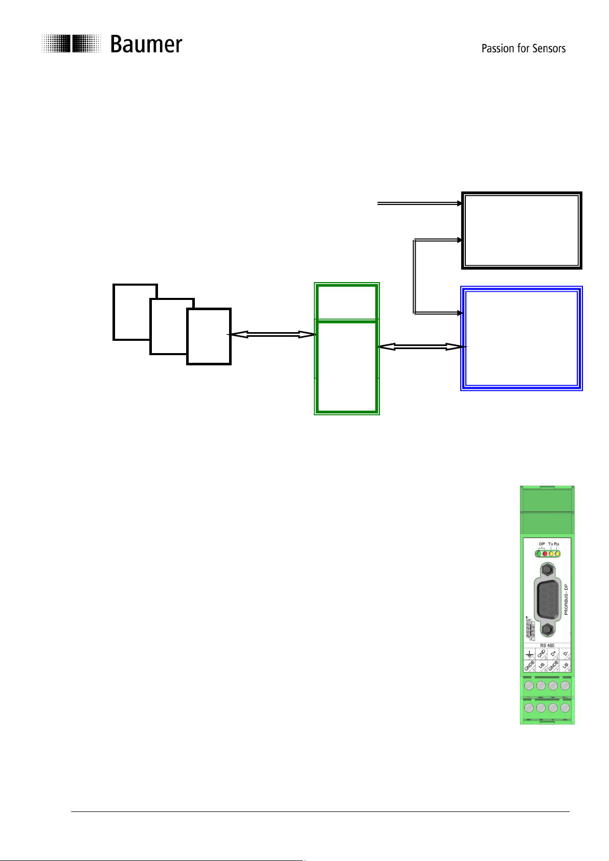
System diagram
CD
Profibus- MPI
RS485
System description
The present manual is meant as support in creating a Profibus project under SIEMENS Step7
Software, in establishing communication with the spindle position displays (SPA) and in
troubleshooting of Profibus errors.
Gateway GK473 (interface converter) is connecting the spindle position displays (= SPAs, for
example N 140 / N 142 / N 150) of the Baumer IVO multicon system to a Profibus-DPcapable PLC. By aid of the gateway the data blocks of the SPA’s RS485 interface are
converted into Profibus DP protocol (and vice-versa).
Some individual gateway functions considerably improve and facilitate PLC programming.
The gateway enables a network of max. 32 SPAs connected to Profibus-DP. The gateway can
be applied with all spindle position displays of the multicon family. Furthermore, several
gateways can be operated at a Profibus in order to connect more SPAs.
The Step7 project and function blocks described in this paper were created using a Step7
Software Version 5.0 + ServicePack2 under Windows 98, together with a S7-315-2DP with an
input module DI16xDC24V and an output module DO32xDC24V/0,5A. However, with only
slight modifications, the project should run in most other Windows / Step7 environments as
well.
SPA
1
SPA
2
SPA
1
GK473
X
GK473
1
PC with
Projecting-
Software Step 7
(Siemens)
Siemens
PLC S7
Profibus-DP
Manual_GK473_S7_Profibus_EN.doc 4/32 Baumer IVO GmbH & Co. KG
04.05.11 Villingen-Schwenningen, Germany
Page 5
2. Gateway Settings
As described in the GK473 manual, set the Node ID in the gateway to an ID of your choice between 04
and 99. In the following example it is „42“.
If the gateway is either the only DP slave or the last DP slave in the Profibus line, the Bus terminator is
activated by setting both DIP switches to ON. In any other case set both DIP switches to OFF.
3. Simatic Manager (Step7 Software)
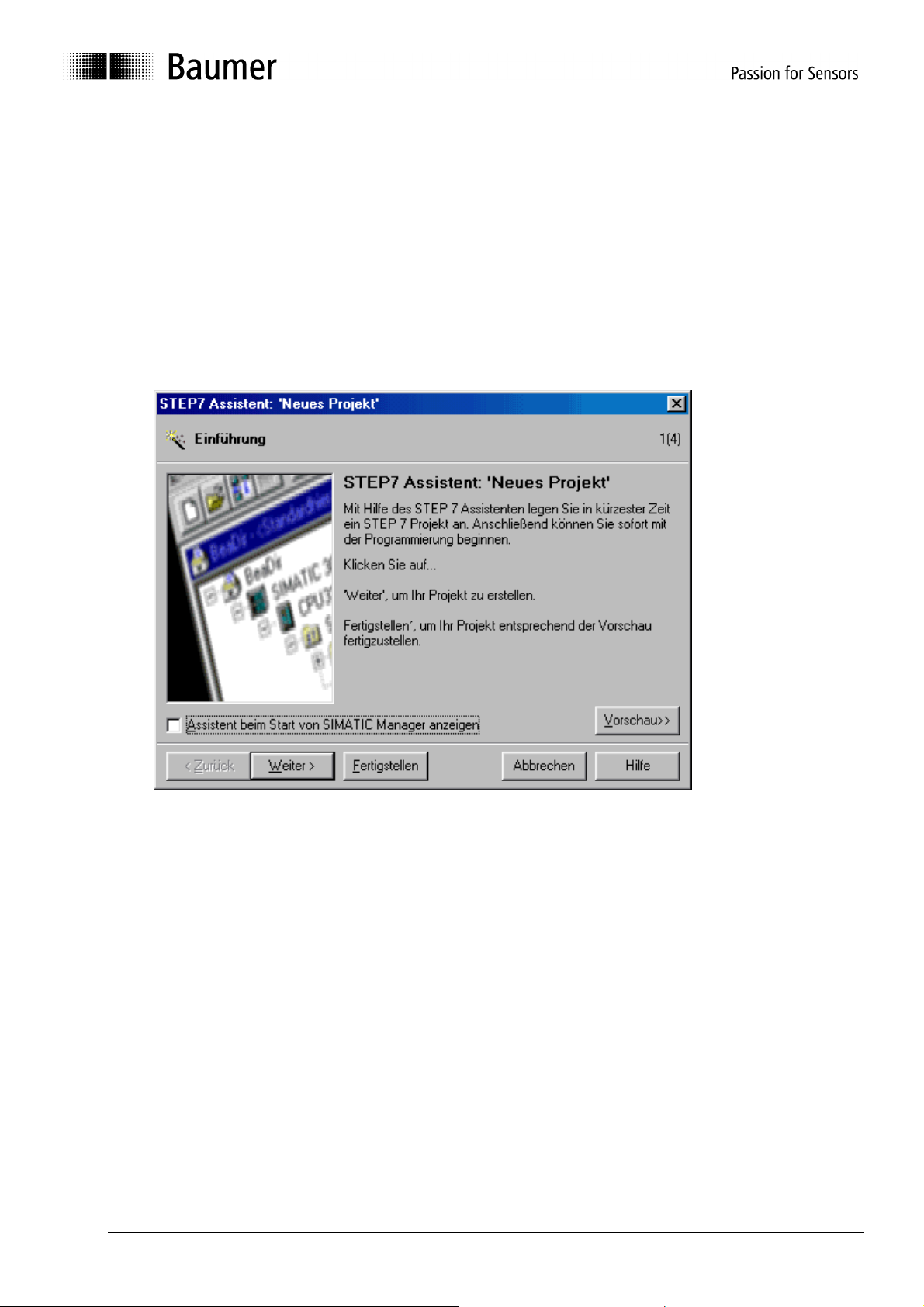
3.1 Creating a new project
Open Simatic-Manager (Step7 Software). For creating a new project call the assistant („File“ Æ
Assistant „New Project“).
Click on „Next“.
Manual_GK473_S7_Profibus_EN.doc 5/32 Baumer IVO GmbH & Co. KG
04.05.11 Villingen-Schwenningen, Germany
Page 6
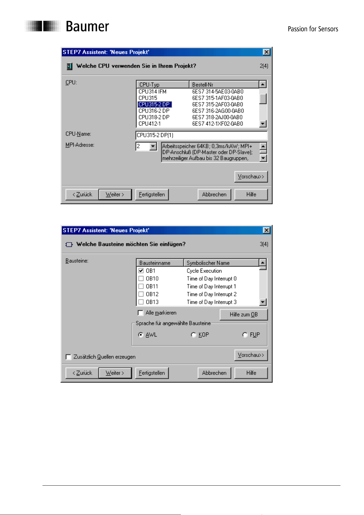
Select your CPU type. Another option is entering an individual CPU name. Click on “next”.
When selecting the blocks to be implemented chose OB1, OB82 and OB86. Select “AWL” (STL,
Statement List) as language for the chosen blocks.
Manual_GK473_S7_Profibus_EN.doc 6/32 Baumer IVO GmbH & Co. KG
04.05.11 Villingen-Schwenningen, Germany
Page 7
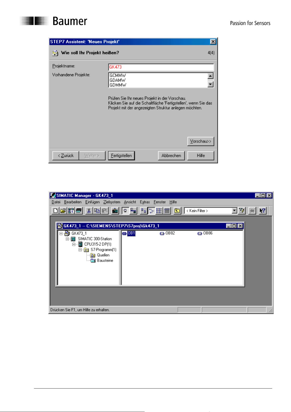
Enter a project name of your choice (for example GK473) and click to „Finish“.
Now the project window showing the already implemented blocks will open.
You have to implement further blocks for the project. Select “paste“ -S7 block- and then the
appropriate option.
Manual_GK473_S7_Profibus_EN.doc 7/32 Baumer IVO GmbH & Co. KG
04.05.11 Villingen-Schwenningen, Germany
Page 8
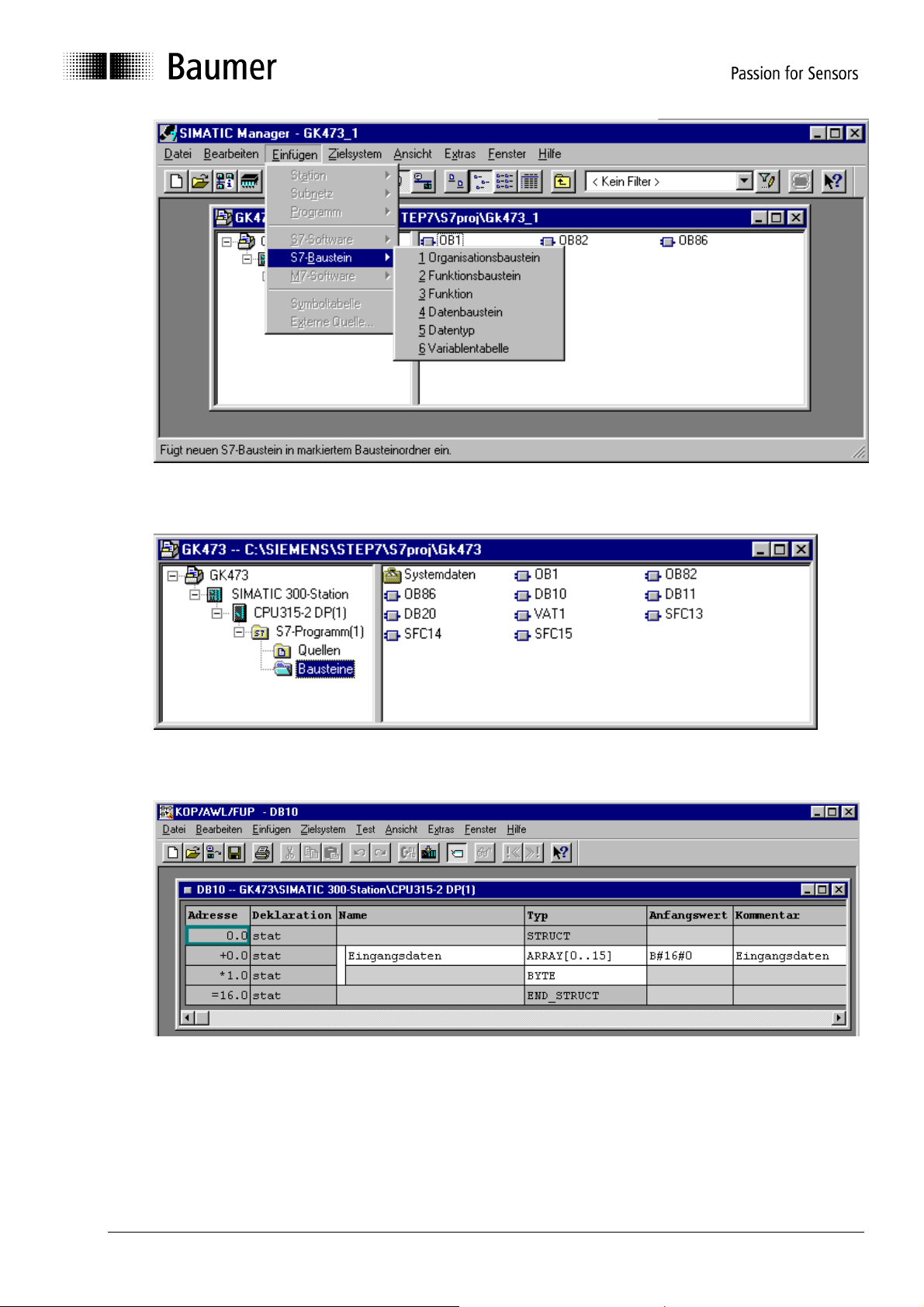
Install all the blocks shown above in successive order. In the following you will find further screenshots
for both data blocks and a chart of variables (optional but recommended for testing purposes).
DB10
Manual_GK473_S7_Profibus_EN.doc 8/32 Baumer IVO GmbH & Co. KG
04.05.11 Villingen-Schwenningen, Germany
Page 9
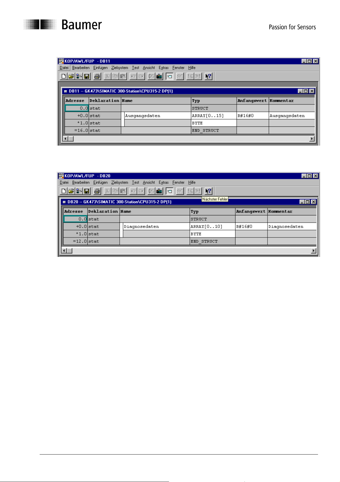
DB11
DB20
Manual_GK473_S7_Profibus_EN.doc 9/32 Baumer IVO GmbH & Co. KG
04.05.11 Villingen-Schwenningen, Germany
Page 10
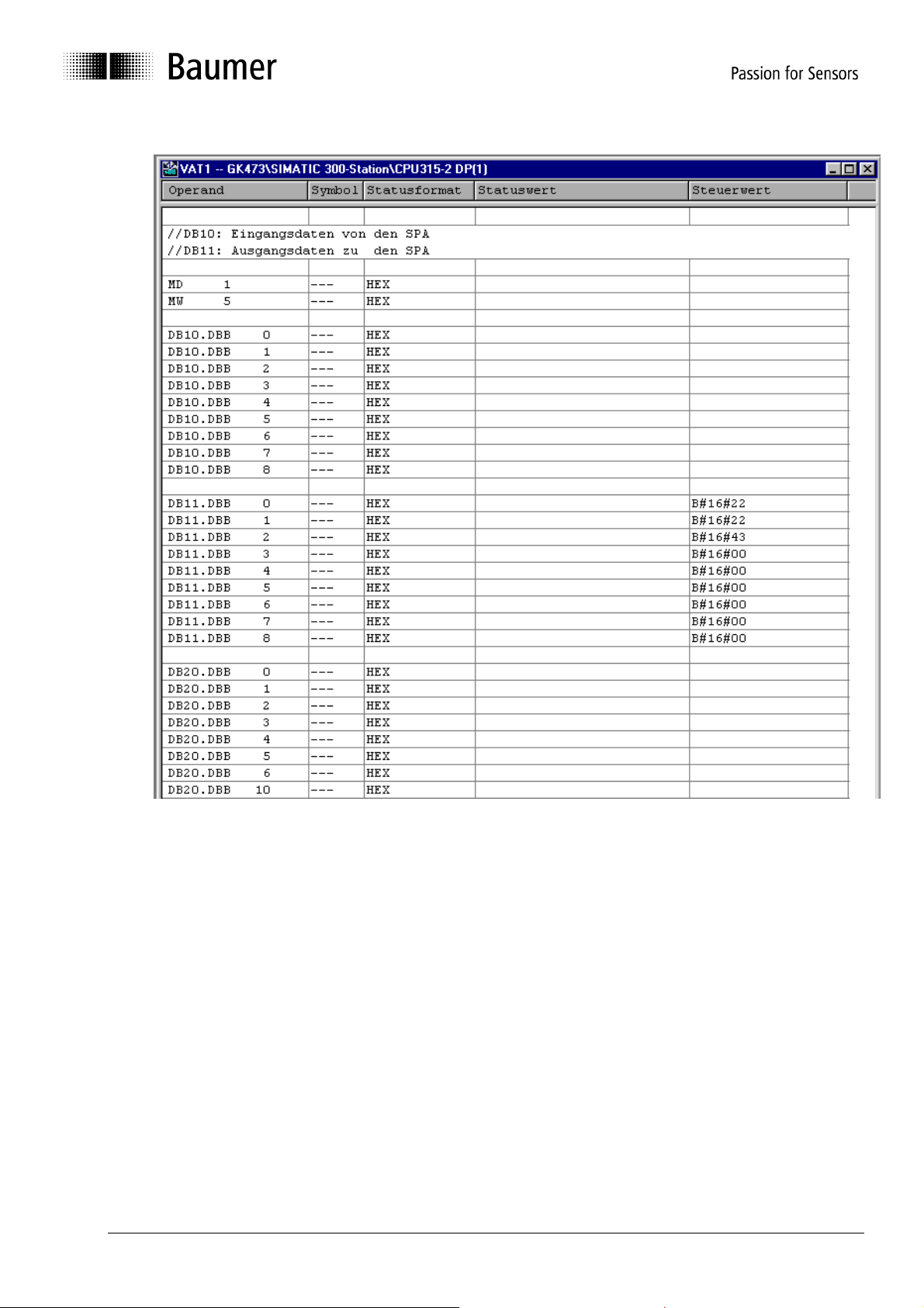
VAT1
After being defined in the SIMATIC Manager, loading of all data blocks into the S7 is imperative (select
blocks, then system of destination Æload)! Otherwise it will not work (neither there will be an error
message).
Manual_GK473_S7_Profibus_EN.doc 10/32 Baumer IVO GmbH & Co. KG
04.05.11 Villingen-Schwenningen, Germany
Page 11

3.2 Import GSD file
Consider the left project window. Branch down to all project elements by clicking on the “+ “ sign. Click
on SIMATIC 300 station.
Among others, the right window will indicate „Hardware“. Double click on „Hardware“.
The hardware window of the Simatic Manager as independent program element „HW config“ will open.
When importing a GSD file no station in the hardware window must be left open. Make sure they are
closed by clicking on „Station“ Æ „Close“.
Importing a GSD file is realized by „Extras“ Æ import GSD file“. Then select the directory with the GSD
file (for example A:\).
After having finalized the import operation re-open the present (File Æ At the bottom will appear a list
of the recently opened stations).
3.3 Hardware-Configuration
For hardware configuration the Profibus must be connected to CPU first – if not already done. Use
right mouse key and click on X2-DP Master bus for insertion of a DP master system.
A new subnet is created by clicking on button „New“
Manual_GK473_S7_Profibus_EN.doc 11/32 Baumer IVO GmbH & Co. KG
04.05.11 Villingen-Schwenningen, Germany
Page 12

I
To enter default settings click on „OK“
Next step is connecting the gateway to Profibus.
HW Config Æ Catalogue Æ other fieldbus devices Æ Gateway Æ GK473.
Drag name „GK473“ to the dotted Bus rail using the left mouse key.
The window „Properties DP-Slave” will open.
Manual_GK473_S7_Profibus_EN.doc 12/32 Baumer IVO GmbH & Co. KG
04.05.11 Villingen-Schwenningen, Germany
Page 13

In this window enter only the Node ID which has to be identical to that previously set at the gateway’s
two rotary switches (Example: 42).
Close window by click on OK .
Drag module “16bit I/O” of GK473 from the hardware catalogue to the window „location /module“ in the
left corner. Upon double click on the newly created line the window of module “16bit I/O” will reopen.
Enter port addresses for input and output data. Different from the screenshot the example is using
identifiers (addresses) 20 to 35.
3.4 Parameterization
Upon double click on the gateway icon of the bus rail in window HW-config the window „Properties DPSlave“ will open. You may proceed alterations of slave number and diagnostic address. The Profibus
node ID has yet been entered above and therefore should already be the correct one.
Manual_GK473_S7_Profibus_EN.doc 13/32 Baumer IVO GmbH & Co. KG
04.05.11 Villingen-Schwenningen, Germany
Page 14

Click on index card „Parameterize“.
Now define the gateway properties as required (see manual) by either double click on the respective
line or by click on „change value“.
Finally the connected peripheral devices have to be configurated. Use left mouse key and click on the
corresponding block in the catalog window, dragging it to the place desired. The following screenshot
is showing the status after configuration.
Manual_GK473_S7_Profibus_EN.doc 14/32 Baumer IVO GmbH & Co. KG
04.05.11 Villingen-Schwenningen, Germany
Page 15

3.5 Store, compile and load
Select „Store and compile“ in HW config to load the hardware configuration into the PLC. This has to
be done after ANY modification in the hardware configuration.
3.6 Organization block OB1
Create a master program as described in the following.
After polling operation of the key for clearing the status-LEDs of OB82 and OB86 the program will
consistently read according to label NOCL the 16 bytes input data into data block DB10 by help of
function SFC14. These are messages of the gateway respectively of the spindle position displays
(SPAs).
Next step is output of the 16 Bit output data by help of function SFC15 of data block DB11 for
consistent transfer to the gateway. The output data imply the commands to the gateway respectively
SPA.
The end of OB1 operates a 16 bit binary counter serving as trigger of the 16 LEDs of the output
module at identifiers 6 and 7. This way a cyclic processing of OB1 is verified.
The organization block OB1 is continuously operated in a cyclic way, reason why data are always
transferred in the same way. The gateway will only consider a transfer as relevant (new) if the count
byte (first byte of a data block) has been altered (refer to manual GK473). Filling respectively
evaluation of the data blocks is not considered in this example.
Manual_GK473_S7_Profibus_EN.doc 15/32 Baumer IVO GmbH & Co. KG
04.05.11 Villingen-Schwenningen, Germany
Page 16

U E 0.3 // Reset key operated? (at input module group ID 0)
SPBN NOCL // clear outputs ID 4 and 5 of OB82
L W#16#0
T AW 4
NOCL NOP 0
CALL SFC 14 // Read input data to DB10
LADDR :=W#16#14 // E/A range of the gateways starts with 20d=14h
RET_VAL:=MW10 // Status and error messages after memory word 10
RECORD :=P#DB10.DBX 0.0 BYTE 16 // Target is data block DB10, start byte 0,
CALL SFC 15 // Output of output data of DB11
LADDR :=W#16#14 // E/A range of the gateways starts with 20d=14h
RECORD :=P#DB11.DBX 0.0 BYTE 16 // Source is data block DB11,
RET_VAL:=MW11 // Status- and error messages after memory word 11
L MD 1 // Visualized by LEDs of
+ L#1 // add Long 1 to AKKU1 (increment)
T MD 1 // Double memory word 1
T AW 6 // Output module group here on IDs 6...7
NOP 0
// Length 16 bytes
// Start byte 0, length 16 bytes
// output module group ID 6 and 7
Manual_GK473_S7_Profibus_EN.doc 16/32 Baumer IVO GmbH & Co. KG
04.05.11 Villingen-Schwenningen, Germany
Page 17

3.7 Organization block OB82
Contrary to the name „Diagnostic alarm” OB82 "I/O Point Fault" is not effected upon DP-Slave alarm
but upon „warnings“ (existing external diagnostic data, no static diagnosis).
Incoming and outgoing events can be evaluated separately.
Organization block OB82 not inserted in the project will make the PLC stop upon occurrence of such
event. To prevent a PLC stop it is sufficient inserting OB82 without program code.
The program in OB82 described in the following first is tracing the logic basic identifier of the DP slave
the warning comes from. After having stored the identifier in memory word 5 it is checked whether it is
an incoming or outgoing event with branching down into several subprograms. In the following
example however the same applies to both cases. The diagnostic data (10 byte) are consistently being
copied into data block DB20. There is a repetition loop since this procedure may take several cycles
and SFC13 is repeated until the procedure has been finalized (BUSY).
At the beginning of the program a characteristic bit pattern is written on the S7 module groups (outputs
ID 4 and 5) to visualize OB82 at the S7 LEDs. The LEDs are cleared by key (see OB1).
L W#16#5555 // Visualize event at LEDs of
T AW 4 // output module group ID 4
L #OB82_MDL_ADDR // Logic basic identifier of DP-Slaves
T MW 5
L #OB82_EV_CLASS // Event class and token
L B#16#39 // Mark incoming event
== I // Identical?
SPB KOMM
GEHT: NOP 0
CALL "DPNRM_DG" // Symbols SFC13
REQ :=TRUE
LADDR :=W#16#3FE // Diagnostic address 1022=3FEh,
RET_VAL:=MW20 // any free memory word available
RECORD :=P#DB20.DBX 0.0 BYTE 11 // Target is data block DB20,
BUSY :=M1.0 // any memory bit used as Busy token;
U M 1.0 // Call memory bit M1.0; set VKE correspondingly
SPB GEHT // Repeat SFC13,
// (B#16#38: outgoing event)
// see Hardware Config Slave
// Beginning byte 0, length 6+5=11 byte
// Repeat as long as Busy
// as long as VKE=1 (linked result)
Manual_GK473_S7_Profibus_EN.doc 17/32 Baumer IVO GmbH & Co. KG
04.05.11 Villingen-Schwenningen, Germany
Page 18

BEA // End current block
KOMM: NOP 0
CALL "DPNRM_DG" // symbol SFC13
REQ :=TRUE
LADDR :=W#16#3FE // Diagnostic address 1022=3FEh,
// see Hardware Config Slave
RET_VAL:=MW20 // any free memory word available
RECORD :=P#DB20.DBX 0.0 BYTE 11 // Target is data block DB20,
// Start byte 0, length 6+5=11 byte
BUSY :=M1.0 // any memory bit used as Busy token;
// Repeat as long as Busy
U M 1.0 // Call memory bit M1.0 ; set VKE correspondingly
SPB KOMM // Repeat SFC13
// As long as VKE=1 (linked result)
3.8 Organization block OB86
OB86 "Loss Of Rack Fault” is effected once (incoming and outgoing) upon DP slave alarm (with
existing external and static diagnostic data).
These events occur with station breakdown and rebooting after power loss of the DP-Slave, bus
interruption or slave alarm messages.
Incoming and outgoing events can be evaluated separately.
Organization block OB86 not inserted in the project will make the PLC stop upon occurrence of such
event.
To prevent a PLC stop it is sufficient inserting OB86 without program code.
The program in OB86 described in the following is first tracing the logic basic address of the DP-slave
the warning comes from and stores the information in memory word 5.
Further the fault ID (possible values hex. C1 to C7) is checked and stored in memory word 7.
After having checked whether it is an incoming or outgoing event the program is branching down into
several subprograms. In the following example however the same applies to both cases. The
diagnostic data (10 byte) are being consistently copied into data block DB20. There is a repetition loop
since this procedure may take several cycles and SFC13 is repeated until the operation has been
finalized (BUSY).
L #OB86_MDL_ADDR // Logic basic address of DP-Slaves
T MW 5
L #OB86_FLT_ID // Fault ID
T MB 7
Manual_GK473_S7_Profibus_EN.doc 18/32 Baumer IVO GmbH & Co. KG
04.05.11 Villingen-Schwenningen, Germany
Page 19

L #OB86_EV_CLASS // Event class and marks
L B#16#39 // Mark incoming event
== I // Identical?
SPB KOMM
GEHT: NOP 0
L W#16#FF //Switch on LEDs of output component group
T AW 4
CALL "DPNRM_DG" // SFC13
REQ :=TRUE
LADDR :=W#16#3FE // Diagnostic address 1022=3FEh,
RET_VAL :=MW20 // any free memory word available
RECORD :=P#DB20.DBX 0.0 BYTE 11 // Target is data block DB20,
BUSY := M1.0 // any memory bit as Busy mark
U M 1.0 // Poll memory word bit M1.0 ab; set VKE
correspondingly
SPB GEHT // Repeat SFC13
BEA // end current block
KOMM: NOP 0
L W#16#FF00
T AW 4
CALL "DPNRM_DG" // SFC13
REQ :=TRUE
LADDR :=W#16#3FE // Diagnostic address 1022=3FEh, s. HW Config
Slave
RET_VAL:=MW20 // any free memory word available
RECORD :=P#DB20.DBX 0.0 BYTE 11 // Target is data block DB20,
BUSY :=M1.0 // any memory bit for Busy mark;
U M 1.0 // Poll memory word bit M1.0; set VKE
correspondingly
SPB KOMM // Repeat SFC13
// (B#16#38 is outgoing event)
// see Hardware Config Slave
// Start of byte 0, length 6+5=11bByte
// Repeat as long as Busy
// as long as VKE=1 (linked result)
// Start byte 0, length 6+5=11 byte
// Repeat as long as Busy
// as long as VKE=1 (linked result)
Manual_GK473_S7_Profibus_EN.doc 19/32 Baumer IVO GmbH & Co. KG
04.05.11 Villingen-Schwenningen, Germany
Page 20

3.9 Troubleshooting
3.10 Evaluating the diagnostic data
Chapter 3.7 „Organization block OB82“ describes diagnostic data readout. For evaluating the
diagnostic data stored in DB20 byte 11must be read off and compared to possible fault numbers. To
do so, byte 11 is checked regarding coincidence with available fault numbers. Upon coincidence the
program skips to the responsible troubleshooting mark.
L DB20.DBB 11 // Read byte 11
L 0 // compare with 0 (00h = no fault, see gateway manual)
==I // if VKE = 1
SPB ENDE // skip to END mark (no error)
L DB20.DBB 11
L 1 // (01h)
==I
SPB EFLA // Flash fault
L DB20.DBB 11
L 2 // (02h)
==I
SPB ERAM // RAM fault
L DB20.DBB 11
L 3 // (03h)
==I
SPB EROM // Eeprom fault
L DB20.DBB 11
L 17 // (11h)
==I
SPB EKON // Configuration fault
L DB20.DBB 11
L 18 // (12h)
==I
SPB EPAR // Parameter fault
L DB20.DBB 11
L 33 // (21h)
==I
SPB ESPA // lost connected SPA
SPA EINT // otherwise internal error
EFLA: NOP 0
//... Code for troubleshooting in case of Flash fault
SPA ENDE
ERAM: NOP 0
//... Code for troubleshooting in case of RAM fault
SPA ENDE
EROM: NOP 0
//...Code for troubleshooting in case of EEPROM fault
SPA ENDE
EKON: NOP 0
//... Code for troubleshooting in case of configuration fault
SPA ENDE
EPAR: NOP 0
//... Code for troubleshooting in case of parameter fault
SPA ENDE
ESPA: NOP 0
//... Code for troubleshooting in case of lost SPA
EINT: NOP 0
//... Code for troubleshooting in case of internal fault
SPA ENDE
ENDE: NOP 0
Manual_GK473_S7_Profibus_EN.doc 20/32 Baumer IVO GmbH & Co. KG
04.05.11 Villingen-Schwenningen, Germany
Page 21

3.11 Remanent profile storing
Data blocks may be defined as „ not process relevant“ (key word: UNLINKED) so that they are stored
only in the remanent memory when being loaded into CPU. Thus they do not burden the CPU
memory unnecessarily and the relevant data are only loaded if required. This procedure is especially
recommended for profiles since they do not require frequent access due to the fact that a profile is
not being altered very often. A data block is marked as “not process relevant” by using the right
mouse key to click on block SIMATIC Manager Æobject properties” and by ticking „unlinked“ in index
card „General – Part 2“ (see screenshot).
Besides an integrated RAM memory, the S7-300-CPUs load memory may also provide an integrated
EPROM part. Otherwise the memory is supplied by battery buffer so that the data will remain even
after PLC switch off. Therefore it is recommended to store SPA profiles in a data block marked “not
process relevant” and to load the profiles only if necessary. This loading operation is realized by
system function SFC 20 BLKMOV.
3.12 Creating an AWL-(STL Statement List) source file
Manual_GK473_S7_Profibus_EN.doc 21/32 Baumer IVO GmbH & Co. KG
04.05.11 Villingen-Schwenningen, Germany
Page 22

By double click to the new AWL (STL) source file a window showing the function’s source code will
open. Afterwards the source file is stored and the program returns to the SIMATIC manager.
Now the project source file must be compiled. Use right mouse key and click to ÆCompile to AWL
(STL)-source file ( in the following FC2) of the SIMATIC-Manager.
3.13 Transferring PLC commands to SPA by gateway
As described in the GK473 manual, possible commands of gateway to SPA have basically the same
structure. For example, a count byte marking the beginning of a new RS485 telegram is followed by
the SPA identifier and then by the true command. Other data may also be attached, for example a
target and/or profile number to write. This Profibus data block has a permanent length of 16 bytes and
must always be transferred in a consistent way.
For consistent transfer Siemens provides the system functions SFC14 (read) and SFC15 (write), that
in our example transfer (SFC15) respectively store (SFC14) 16 bytes each of a data block.
Manual_GK473_S7_Profibus_EN.doc 22/32 Baumer IVO GmbH & Co. KG
04.05.11 Villingen-Schwenningen, Germany
Page 23

3.14 Structure of profile data block DB98
Profile data block DB98 implies all profiles of each single SPA connected .The individual targets are
written into the data block in successive order and each SPA is capable of memorizing up to 100
targets. When adapting this data block it has to be made sure that it is in line with function FC14. For
example, the DB is not only for storing targets but also other data, or maybe only 15 profiles are
required instead of 100. Since the offset is explicitly calculated by permanent values it has to be
considered in the calculation. If further values besides the targets have to be stored or read in, the
additional output variables must be defined in the function.
: : : : : : :
: : : : : : :
: : : : : : :
: : : : : : :
: : : : : : :
: : : : : : :
Manual_GK473_S7_Profibus_EN.doc 23/32 Baumer IVO GmbH & Co. KG
04.05.11 Villingen-Schwenningen, Germany
Page 24

4. Functions
4.1 Overview on function
Following functions are on CD, both as project files as well as simple text files where an AWL (STLStatement List) source file can be copied
FC 1 Converting ASCII number (6 Byte) into real number
FC 5 - Converting real number into ASCII (6 Byte)
FC 10 – Read current value
FC 11 – Read target off current SPA profile
FC 12 – Read target off defined SPA profile
FC 13 – Write target into defined SPA profile
FC 14 – Read target off profile data block
FC 15 – Automatic placing of identifier/address
FC 16 – Program bit parameter
FC 17 – Change profile
FC 18 – Collective information „SPA connected“
FC 19 – Collective information „Check Position“
FC 21 – Automatic SPA scanning operation on/off
Following data blocks and memory bytes, memory words and double memory words are applied by the
previously described functions:
DB95 16 byte data block to store data that are read in by gateway
DB96 16 byte data block to store outgoing data to the gateway
DB97 6 byte data block to convert from ASCII into Real
DB98 DB to store all targets of a single SPA
DB99 Applies to global variables, for example Busy, current value_real, Timeout as well as other
MW 1 Memory word to store the respectively current status of the gateway’s master counter.
M50.0 – M54.7 Memory range applied by function FC16.
Important!
Since it takes the SPA a little time to answer the calls some functions have to be called
repeatedly.
This is indicated by a „Busy“ message (Busy bit). It is up to the operator to have
the OB functions repeated until the Busy bit is no longer active in order to make
sure that the data being read in are truly the current ones and do not rely to a
previous data call.
!
variables required by the function blocks.
Manual_GK473_S7_Profibus_EN.doc 24/32 Baumer IVO GmbH & Co. KG
04.05.11 Villingen-Schwenningen, Germany
Page 25

4.2 The global variables, data block DB99
Since many functions are called off repeatedly and the variables defined in the local function blocks
are valid for calling operations only they are stored in data block 99. This way they can be accessed
any time. The chart below gives on overview on the stored variables.
4.3 Busy bit, Timeout bit and Error bit
All functions awaiting an SPA reply will come with a Busy bit, Timeout bit and an Error bit.
Busy bit
The Busy bit indicates that the SPA has not yet replied and that the function has to be repeated. The
true command of the function is not transferred twice but it is only checked whether recent data are yet
available at the gateway. Function polling goes together with setting of Busy bit to make sure
that the function is really repeated until the Busy bit is not active anymore.
Timeout bit
No new data provided within the time window defined will result in setting the Timeout bit what is done
by a timer that is started upon command transfer.
Error bit
In case system functions SFC14 or SFC 15 signalize a polling error latter is stored and can be verified
by the operator. The error bit indicates that an error has occurred.
Manual_GK473_S7_Profibus_EN.doc 25/32 Baumer IVO GmbH & Co. KG
04.05.11 Villingen-Schwenningen, Germany
Page 26

4.4 FC 1 - ASCII Number (6 Byte) in real numbers
This function is required by FC10, FC11, FC12 and FC13 to convert the SPA data received into a real
number (with floating point according to IEEE-754).
Incoming data in ASCII format are being read off a DB (in the example it is DB20) and converted to be
depicted as real numbers with floating point.
First the ASCII sign is converted into an integer number and multiplied by 10. Same applies to the
following ASCII sign that is then added to the previous result, again multiplied by 10 and so on up to
the latest number which is only added and instead of being multiplied divided by 100 in order to end up
with two decimals.
Example: (positive value)
0x31 Æ 1 multiplied by 10 -> 10
0x32 Æ 2 + 10 = 12 multiplied by 10 Æ 120
0x33 Æ 3 + 120 = 123 multiplied by 10 Æ 1230
0x34 Æ 4 + 1230 = 1234 multiplied by 10 Æ 12340
0x38 Æ 8 + 12340 = 12348 multiplied by 10 Æ 123480
0x36 Æ 6 + 123480 =123486 divided by 100 Æ 1234,86
Analog with negative sign:
0x2d Æ - (negative sign, read 5 numbers only)
0x34 Æ 4 = 4 multiplied by 10 Æ 40
0x33 Æ 3 + 40 = 43 multiplied by 10 Æ 430
0x32 Æ 2 + 430 = 432 multiplied by 10 Æ 4320
0x38 Æ 8 + 4320 = 4328 multiplied by 10 Æ 43280
0x36 Æ 6 + 43280 = 43286 divided by 100 Æ 432,86
Negate number due to negative sign Æ -432.86
A negative number makes the function run in another sub-program than a positive number. Similar to
the SPA display the range is limited, for positive numbers. 9999.99 max, for negative numbers.–999.99
max.
4.5 FC 5 – Real number in ASCII
FC13 requires this function to convert the target received in real format into ASCII format by using data
block 97 where the target in ASCII format is written after conversion. The conversion is realized as
follows:
First the target is multiplied by 100 to eliminate the digits after the point. The floating point number can
be converted without rounding error into an integer number that is now converted into BCD (Binary
Coded Decimal). Since loading 4 bytes only ( i.e. BCD number) under AWL (STL-Statement List) is not
possible, always 8 bytes i.e. 2 numbers must be loaded and treated separately by shifting operations
and outmasking. The numbers are successively written into DB97 in ASCII format by adding the offset.
Example: Target 123,45:
First the target is multiplied by 100: 12345
Readout in BCD:
BYTE BYTE BYTE
0 1 2 3 4 5
Access byte by byte for example will make the last two figures load into the battery( 01000101 binary).
4 5
010
0
010
1
To achieve number 4 the bits must be shifted by 4 digits to the right in order to eliminate number 5. The
following bits are filled by zeroes.
Manual_GK473_S7_Profibus_EN.doc 26/32 Baumer IVO GmbH & Co. KG
04.05.11 Villingen-Schwenningen, Germany
Page 27

0 4
000
0
010
0
To achieve number 5 the first 4 bits are masked out using an UND link. 1111 is loaded into the battery
and linked to 0100 0101 UND.
010
0
UNDLinked to
000
0
Result 000
0
010
1
111
1
010
1
To both numbers the ASCII offset is added what equals 0x34 and 0x35 that is written into the DB.
4.6 FC 10 – Read current value
The function ”read current value” is reading the current value off the SPA addressed. The function is
given the SPA identifier as integer number (1,2,3 ...). The function then is converting the SPA identifier
into the format required by the gateway. Returned is the current SPA value in real format. Furthermore
the function outputs a Busy bit, a Timeout bit and an Error bit.
Call function:
CALL FC 10
SPA ID: INT;
Time_Out: BOOL;
Error: BOOL;
Busy: BOOL;
Current value_Real: REAL;
First the function calls SFC14 for reading in the current count byte to be stored in MW1. Second step is
generating the command to be sent to the gateway. To do so, MW1 is incremented and the SPA
identifier converted into ASCII. MW1, SPA identifier and command byte are then written into DB96.
Remaining digits are filled by zeroes.
The command is sent to the gateway by SFC15 with subsequent start of a timer. Also the Busy bit is
set to prevent the command from being resent to the gateway during repeated function call. Only the
read in routine of the function will be proceeded again.
Prior to the read-in operation the timer is checked. When having expired, the program directly skips to
label/mark Timeout. The Timeout bit is set whereas the Busy bit is reset.
If the timer has not yet expired the read-in operation will be proceeded by SFC14. The count bytes are
compared to reckon whether new data are provided. The “ancient” count byte was stored in DB99 and
compared with the recent count byte provided by DB95 prior to sending the command. In case the
count bytes are not identical the gateway is in receipt of the SPA reply and the function will reset the
Busy bit.
The new data are processed by aid of FC1 that is converting the current value provided in ASCII
format by DB95 into a floating point number. Returned is FC10. The Busy memory word is reset and it
is checked whether there has any error occurred in system functions SFC14 and SFC15 what is
registered by the error bit.
Manual_GK473_S7_Profibus_EN.doc 27/32 Baumer IVO GmbH & Co. KG
04.05.11 Villingen-Schwenningen, Germany
Page 28

4.7 FC 11 – Read target off current SPA profile
This function is for reading off the current profile of the addressed SPA. The SPA identifier is passed to
the function as integer number and returned is the target.
The function runs identical to FC10, but instead of the current value being read in FC1 only the target
being read in is converted.
Call function:
CALL FC 11
SPA_ID := INT
Time_Out := BOOL
Error := BOOL
Busy := BOOL
Target_Real := REAL
Active_profile := INT
4.8 FC 12 – Read target off defined SPA profile
This function is for reading a defined target from a profile presently not active. FC12 is given both SPA
identifier and the selected profile number for read out. Returned is the target.
The function runs identical to FC10 and FC11 with the only difference that when generating the
command also the required profile number is first converted into ASCII format and then also written
into DB96.
Call function:
CALL FC 12
SPA_ID := INT
Profile number := INT
Time_Out := BOOL
Error := BOOL
Busy := BOOL
Target_Real := REAL
4.9 FC 13 – Write target into defined SPA profile
This function is for writing a target in real format into a certain SPA profile. The function is given the
respective SPA identifier, the required profile number to write in as well as the target in REAL format.
Call function:
CALL FC 13
SPA_ID := INT
Profile number := INT
Target := REAL
Time_Out := BOOL
Error := BOOL
Busy := BOOL
Manual_GK473_S7_Profibus_EN.doc 28/32 Baumer IVO GmbH & Co. KG
04.05.11 Villingen-Schwenningen, Germany
Page 29

4.10 FC 14 – Read target off profile data block
Of course the profiles can also be stored by PLC. This function is meant as example for a possible
profile arrangement. Access is on DB98 where the SPA profiles (1-99) are listed. The pointer allows
immediate access to a defined target. The function is given both SPA identifier and profile number in
order to calculate the offset and to reply the target.
Example: SPA-identifier = 4
Profile nr. = 8
The function will now read the target off DB98.DBB 1228.
The formula for calculating the offset is as follows:
(SPA_ID
– 1)x400 + (profile number – 1)x4
In case DB98 is adapted to prevailing requirements, the calculation of the offset has to be adapted as
well. If for example only 10 profiles are required, the memory capacity of the block is reduced and also
the offset is calculated in a different way. With 10 profiles for example the formula is as under:
(SPA_ID –1)x40 + (profile number –1)x4
Call function:
CALL FC 14
SPA_ID :=3
Profile number:=1
Target :=MD130
4.11 FC 15 – Automatic identifier (address) designation
This function is giving a broadcast command to all SPAs connected what enables automatic placing of
the SPA identifiers in successive order. To place the identifier, the shaft of the respective SPA must be
turned by at least a half, the direction does not matter.
The function must be given the identifier to start with and the total of SPAs. Thus it is possible to place
the identifier also with SPAs that are connected later by simply naming the next identifier and the
number of additional SPAs to be addressed.
Call function:
CALL FC 15
Start_Adr := INT
Anzahl_SPA := INT
Time_Out := BOOL
Fehler := BOOL
Busy := BOOL
4.12 FC 16 – Set bit parameter
This function is for writing the bit parameters into the SPA. The function applies the memory range
from M50.0 to M54.7. Parameters are given as Bool in case of two options only respectively as an
integer number in case of more than two options. 0 is representing a binary zero, 1 a binary 1, 2 for
binary 10 and 3 for binary 11. Parameters to hide arrows, Offset and target are parameters with more
than two options (example arrows: UP/DOWN /UNI/ OFF).
Data_4_5 makes the SPA identifier entered as integer number what the function will convert
correspondingly.
Manual_GK473_S7_Profibus_EN.doc 29/32 Baumer IVO GmbH & Co. KG
04.05.11 Villingen-Schwenningen, Germany
Page 30

Positioning direction 0/1 (UP/DOWN)
Counting direction 0/1 (UP/DOWN)
Arrows 0/1/2/3 (UP/DOWN/UNI/OFF)
Rounding the current value 0/1 (OFF/ON)
Turn display 0/1 (OFF/ON)
Offset 0/1/2/3 (NORM/MAST/SLAV/WKZR)
Hide target 0/1/2 (OFF/ON/EVER)
Data_4_5 1..99 (SPA-Identifier)
Call function
CALL FC 16
SPA_identifier := INT;
Positioning direction := BOOL;
Counting direction := BOOL;
Arrows := INT;
Rounding the current value := BOOL;
Turn display := BOOL;
Offset := INT;
Hide target := INT;
Data_4_5 := INT;
4.13 FC 17 – Program profile
This function is for selecting a SPA profile. The function comprises SPA identifier and the requested
profile number. Both information is converted into ASCII and written into the respective command to be
sent.
Call function
CALL FC 17
SPA_identifier := INT
Profile number := INT
Time_Out := BOOL
Error := BOOL
Busy := BOOL
4.14 FC 18 – Collective information “connected SPA”
This function is for calling the gateway function „SPA connected“. The command generated comprises
the imperative count byte, the gateway address (20h) and the command byte for internal processing
(40h= ‘@’) as well as the command byte for special functions, in the example 41h. Following is a block
number (1..3 (21..23h)) comprising a group of 10 SPAs each.
Replied is again a 16 byte data block of the following structure: Count byte, gateway address, byte for
internal processing and command byte followed by the addressed block. The next byte comprises the
total of SPAs connected followed by their individual identifiers (please refer also to gateway manual
GK473, chapter 3.5).
Presently the function calls and reads the first block only. The function replies the total of SPAs
connected. If the function is intended for calling off other blocks due to requiring the identifiers of the
connected SPAs the function has to be correspondingly extended and adapted.
Manual_GK473_S7_Profibus_EN.doc 30/32 Baumer IVO GmbH & Co. KG
04.05.11 Villingen-Schwenningen, Germany
Page 31

Call function
CALL FC 18
Total_SPA := INT
Time_Out := BOOL
Error := BOOL
Busy := BOOL
4.15 FC 19 – Collective information “Check Position”
This function is for accomplishing the gateway function command „Check Position“.
The command is processed in the same way as previously described. Same restrictions as for block
processing do apply. Latter is not existing and has to be completed if required.
Call function
CALL FC 19
Number_not_in_posi := INT
Time_Out := BOOL
Error := BOOL
Busy := BOOL
4.16 FC 21 – Automatic SPA scanning operation ON or OFF
This function is for switching ON or OFF the automatic SPA scanning operation. The desired option is
entered by aid of a bool variable. For automatic scanning operation ON, enter 1 = TRUE respectively 0
= FALSE for OFF.
Although by this command the gateway default parameter is overwritten it does not mean a permanent
alteration. Some commands require switching off the automatic scanning operation since they are only
valid until another command is received – for example indicate SPA identifier in the lower display or
with any automatic placing of identifiers.
Call function
CALL FC
Auto_Scan_On := BOOL
Time_Out := BOOL
Error := BOOL
Busy := BOOL
Manual_GK473_S7_Profibus_EN.doc 31/32 Baumer IVO GmbH & Co. KG
04.05.11 Villingen-Schwenningen, Germany
Page 32

5. Annex
5.1 Abbreviations applied
ASCII American Standard Code for Information Interchange
AWL PLC programming language „Anweisungsliste“ (STL – Statement List)
BCD Binary Coded Decimal
BiSS Bidirectional Sensor interface
CRC Cyclic Redundancy Check
DB Datenbaustein
FC Function
FB Function block
GSD Device standard file
IC Integrated Circuit
LSB Lowest Significant Bit or Byte
MSB Most Significant Bit or Byte
MT Multiturn
OB1 Operation- Block
PLC Programmable Logic Control
PROFIBUS Process Field
RS485 Radio Sector 485, physical standard for differential data transfer
SPA Spindle position display
SSI Synchron Serial Interface
ST Singleturn
TÜV Technischer Überwachungs-Verein (German Technical Regulations Authority)
Bus
Manual_GK473_S7_Profibus_EN.doc 32/32 Baumer IVO GmbH & Co. KG
04.05.11 Villingen-Schwenningen, Germany
 Loading...