

Page 1

Manual
Absolute encoder with Profibus-DP
with functional extensions according to
Profibus-DPV1 and DPV2
Firmware Version 1.00 and up
Baumer IVO GmbH & Co. KG
Dauchinger Strasse 58-62
DE-78056 Villingen-Schwenningen
Phone +49 7720 942-0
Fax +49 7720 942-900 05.12 · 174.01.050/4
info.de@baumerivo.com Irrtum sowie Änderungen in
www.baumer.com Technik und Design vorbehalten.
Page 2

Contents Page
1. Introduction 5
1.1. Scope of delivery 5
1.2. Product classification 5
2. Safety and operating instructions 6
3. Product family 7
4. Commissioning 8
4.1. Mechanical mounting 8
4.2. Electrical connection 8
4.2.1. Cabling 8
4.2.2. Setting the user address 9
4.2.3. Terminating resistor 9
4.2.4. Connecting the bus cover 9
5. Projecting 11
5.1. Importing the GSD file 11
5.2. Encoder bus implementation 11
5.3. Assigning the user address 11
5.4. Assigning addresses for input and output data 11
5.5. Parameterization 12
5.5.1. General 12
5.5.2. Parameter Assignment 12
5.5.3. Clock synchronisation 15
5.6. Implementing the system functions for alarm handling 16
5.7. Compilation and load of hardware and software configuration 16
6. Profibus operation 17
6.1. Master Class 1 (Parameterization master) 17
6.2. Status indicator (multi-colour LED) 17
6.3. Telegram 81 of profile PROFIdrive 18
6.4. Position readout 19
6.5. Error signals in G1_XIST2 19
6.6. Preset function 19
6.7. Alarms 20
6.8. Warnings 21
6.9. Acyclic data communication according to DPV1 21
6.9.1. Overview 21
6.9.2. DS_Write 21
6.9.3. DS_Read 22
6.9.4. PROFIdrive parameter 918 PROFIBUS node ID 23
6.9.5. PROFIdrive parameter 922 telegram type 24
6.9.6. PROFIdrive parameter 964 device ID 25
6.9.7. PROFIdrive parameter 965 profile number 26
6.9.8. PROFIdrive parameter 971 transfer to non-volatile memory 27
6.9.9. PROFIdrive parameter 979 sensor format 28
6.9.10. Profile parameter 65000 preset value 30
6.9.11. I&M parameter 65000 block 0 31
7. System documentation: Profibus-DP 33
7.1. General information 33
7.2. GSD file 33
7.3. Encoder operating paramters 34
7.4. Data exchange between PROFIBUS-DP devices 35
7.5. Parameterization and configuration 36
7.5.1. Parameterization 36
7.5.2. Configuration 36
7.6. Diagnostic signals 36
7.6.1. Description of the diagnostic data block 37
7.6.2. Alarms 37
8. Troubleshooting – FAQ 38
Manual_ProfibusDPV2_BIDE_EN.docx 2/41 Baumer IVO GmbH & Co. KG
22.11.12 Villingen-Schwenningen, Germany
Page 3

8.1. FAQ: Projecting 38
8.1.1. Where do I get an encoder manual? 38
8.1.2. Where do I get the appropriate GSD file? 38
8.1.3. Class3 or Class4 parameterization? 38
8.1.4. Input of 32bit parameter data in Siemens Step7 software 38
8.2. FAQ: Operation 39
8.2.1. Position readout 39
8.2.2. How to set and save a preset value ? 39
8.2.3. What is the LED in the bus cover for? 39
8.2.4. How to alter the resolution ? 40
8.2.5. How to read diagnostic data out of the control? 40
8.3. FAQ: Troubleshooting 40
8.3.1. No encoder communication (LED yellow continuous) 40
8.3.2. No encoder communication (LED flashing red once per second) 41
Manual_ProfibusDPV2_BIDE_EN.docx 3/41 Baumer IVO GmbH & Co. KG
22.11.12 Villingen-Schwenningen, Germany
Page 4

Disclaimer of liability
The present manual was compiled with utmost care, errors and omissions reserved. For this reason
Baumer IVO GmbH & Co. KG rejects any liability for the information compiled in the present manual.
Baumer IVO nor the author will accept any liability for direct or indirect damages resulting from the use of the
present information.
At any time we should be pleased receiving your comments and proposals for further improvement of the
present document.
Registered trademarks
SIEMENS®, SIMATIC®, Step7® und S7® are registered trademarks of Siemens AG. PROFIBUS, the
PROFIBUS Logo and PROFIdrive are registered trademarks of the PROFIBUS user organization respectively
of PROFIBUS International (PI).These and other names applied in the present manual that at the same time
are registered trademarks are not correspondingly marked. Having omitted the respective marking does not
necessarily imply that the names are not registered trademarks or that there are no existing patents and
protected patented designs.
Manual_ProfibusDPV2_BIDE_EN.docx 4/41 Baumer IVO GmbH & Co. KG
22.11.12 Villingen-Schwenningen, Germany
Page 5

1. Introduction
Product
GSD file
Product family
GBAMW
GBAM09F6.gsd
multivoPlus - Singleturn
GBLMW
GBMM09F6.gsd
multivoPlus - Multiturn
GBMMW
GBMM09F6.gsd
multivoPlus - Multiturn
GCAMW
GCAM09F6.gsd
magtivo® - Singleturn
GCMMW
GCMM09F6.gsd
magtivo® - Multiturn
GEMMW
GXMM09F6.gsd
multivo® - Multiturn (stainless steel)
GXAMW
GXAM09F6.gsd
multivo® - Singleturn
GXLMW
GXMM09F6.gsd
multivo® - Multiturn
GXMMW
GXMM09F6.gsd
multivo® - Multiturn
Product
GSD file
Product family
GBAMS
GBAM09F6.gsd
multivoPlus - Singleturn
GBLMS
GBMM09F6.gsd
multivoPlus - Multiturn
GBMMS
GBMM09F6.gsd
multivoPlus - Multiturn
GCAMS
GCAM09F6.gsd
magtivo® - Singleturn
GCMMS
GCMM09F6.gsd
magtivo® - Multiturn
GXAMS
GXAM09F6.gsd
multivo® - Singleturn
GXLMS
GXMM09F6.gsd
multivo® - Multiturn
GXMMS
GXMM09F6.gsd
multivo® - Multiturn
1.1. Scope of delivery
Please check the delivery upon completeness prior to commissioning.
Depending on encoder configuration and part number delivery is including:
Basic encoder
Profibus bus cover
Sealing bolt for any unused cable gland
CD with GSD file and manual (also available as download in the Internet)
1.2. Product classification
Shaft encoders
End shaft encoders
Manual_ProfibusDPV2_BIDE_EN.docx 5/41 Baumer IVO GmbH & Co. KG
22.11.12 Villingen-Schwenningen, Germany
Page 6

2. Safety and operating instructions
Supplementary information
The present manual is intended as a supplement to already existing documentation (catalogues, product
data sheets and mounting instructions).
The manual must be studied carefully prior to initial commissioning of the equipment.
Intended purpose of the equipment
The encoder is a precision measurement device. It is utilized to determine angular positions and
revolutions, and to prepare and supply measured values in the form of electrical output signals for the
downstream device. Encoders may only be used for this purpose.
Commissioning
The encoder must be initialised and mounted only by a qualified expert.
Observe the operating instructions of the machine manufacturer.
Safety instructions
Check all electrical connections prior to commissioning of the equipment.
If mounting, electrical connections or any other work performed at the encoder and the equipment is not
correctly executed this can result in malfunction or failure of the encoder.
Corresponding safety precautions must be provided and observed to exclude any risk of personal injury,
damage to material or operating equipment as a result of encoder failure or malfunction.
Encoders must not be operated outside the specified limited values (see further documentation).
Failure to observe these safety instructions can result in malfunctions, material damage or personal injury.
Transport and storage
Only ever transport or store the encoder in its original packaging.
Never drop the encoder nor expose it to major shocks.
Mounting
Avoid impacts or shocks on housing and shaft/end shaft.
End shaft/Hollow shaft encoder: Open clamping ring completely before mounting the encoder
Avoid any twist or torsion on the housing.
Shaft encoders: never make rigid connections between encoder shaft and drive shaft.
Do not open the encoder or proceed any mechanical modifications.
Shaft, ball bearings, glass pane or electronic components can be damage thereby and a safe and reliable
operation is no longer guaranteed.
Electrical commissioning
Do not proceed any electrical modifications at the encoder.
Do not proceed any wiring work while encoder is live.
Never plug or unplug connector while encoder is live (the bus cover however may be removed or docked
to the basic encoder when live).
Ensure that the entire system is installed in line with EMC/EMI requirements. Operating environment and
wiring have an impact on the electromagnetic compatibility of the encoder. Install encoder and supply
cables separately or far away from sources with high emitted interference (frequency converters,
contactors, etc).
When working with consumers with high emitted interference provide separate encoder supply voltage.
Completely shield encoder housing and connecting cables..
Connect encoder to protective earth (PE) using shielded cables. The braided shield must be connected to
the cable gland or connector. Ideally, aim at dual connection to protective earth (PE), i.e. housing by
mechanical assembly and cable shield by the downstream devices. In case of earth loop problems, earth
at least on one side.
Failure to observe these instructions can result in malfunctions, material damage or personal injury!
Manual_ProfibusDPV2_BIDE_EN.docx 6/41 Baumer IVO GmbH & Co. KG
22.11.12 Villingen-Schwenningen, Germany
Page 7
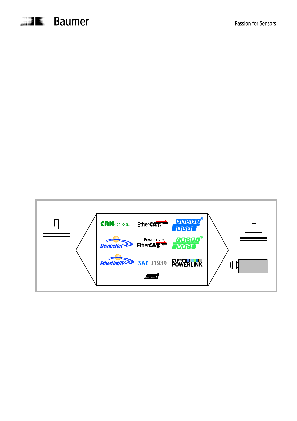
3. Product family
bus cover
complete encoder
basic encoder
The product family architecture is modular. Depending on what is required from the encoder, the basic
encoder and bus covers can be combined at will with the selected bus system.
The basic encoders differ in terms of accuracy, ambient conditions and the utilized sensing principle.
Bus cover
The bus cover accommodates the field bus interface and the complete electronics for processing the
measured values. EtherNet/IP communication is performed via the specialized EtherNet/IP-ASIC ERTEC200
with integrated high-performance microcontroller ARM9.
Magres / magtivo®
Utilizes a magnetic sensing principle and endures harsh industrial environments.
Procoder / multivo®
Utilizes a photoelectric sensing principle and is the recommended product for precise applications.
Dignalizer / activo® / multivoPlus®
Utilizes a photoelectric sensing principle with integrated analog/digital signal conversion and is the product to
choose for ultra-precise sensing applications.
The bus covers differ by the respectively integrated bus interface.
Available bus interfaces: CANopen, DeviceNet, EtherCAT, Ethernet/IP, Profibus-DP, Profinet, Powerlink,
Power over EtherCAT, SAE J1939, SSI.
All encoders enable parameterization by bus interface.
Functional principle:
Manual_ProfibusDPV2_BIDE_EN.docx 7/41 Baumer IVO GmbH & Co. KG
22.11.12 Villingen-Schwenningen, Germany
Page 8
4. Commissioning
Properties
Data
Impedance in Ohm
135 to 165 at 3 to 20 MHz
Operating capacity (pF/m)
less than 30
Loop impedance (Ohm/km)
less than 110
Core diameter (mm)
greater than 0.64
Core cross section (mm)
greater than 0.34
Baudrate in
kBaud
9,6
19,2
93,75
187,5
500
1500
3000
6000
12000
Line distance
in m
1200
1200
1200
1000
400
200
100
100
100
4.1. Mechanical mounting
Shaft encoders
Mount the encoder by help of the mounting holes and three screws (square flange: 4 screws) provided at
the encoder flange. Observe thread diameter and depth.
There is an alternative mounting option in any angular position by eccentric fixings, see under
accessories.
Connect drive shaft and encoder shaft by using an appropriate coupling. The shaft ends must not touch
each other. The coupling must compensate temperature and mechanical tolerances. Observe the
maximum permitted axial or radial shaft load. For appropriate couplings please refer to accessories.
Tighten the mounting screws firmly.
End shaft/hollow shaft encoders
Mounting by clamping ring
Prior to mounting the encoder open the clamping ring completely. Push encoder onto the drive shaft and
tighten the clamping ring firmly.
Adjusting element with rubber buffer
Push the encoder onto the drive shaft and insert the cylindrical pin into the adjusting element (provided by
customer) and the rubber buffer.
Adjusting angle
Push the encoder onto the drive shaft. Insert adjusting angle into the encoder’s rubber buffer and fasten
the adjusting angle at the contact surface.
Stud screw
Push the encoder onto the drive shaft and insert the stud screw provided by customer into the encoder’s
rubber buffer.
Spring coupling
Fasten the spring coupling at the mounting holes of the encoder housing using screws. Push the encoder
onto the drive shaft and mount the spring coupling to the contact surface.
4.2. Electrical connection
Ever store and transport the bus cover in the ESD bag only.
For electrical connection remove the bus cover as follows:
Release the fastening screws of the bus cover
Carefully loosen the bus cover and lift off in an axial direction
4.2.1. Cabling
EN 50170 specifies two types of PROFIBUS cable, type A and B. Type B is obsolete and should not be used
in new applications. With type A all transmission rates up to 12Mbit/s are possible. Common baud rate in
clock synchronous operation according to PROFIBUS-DPV2 is 12Mbit/s.
Transmission speed depending on line distance
Manual_ProfibusDPV2_BIDE_EN.docx 8/41 Baumer IVO GmbH & Co. KG
22.11.12 Villingen-Schwenningen, Germany
Page 9
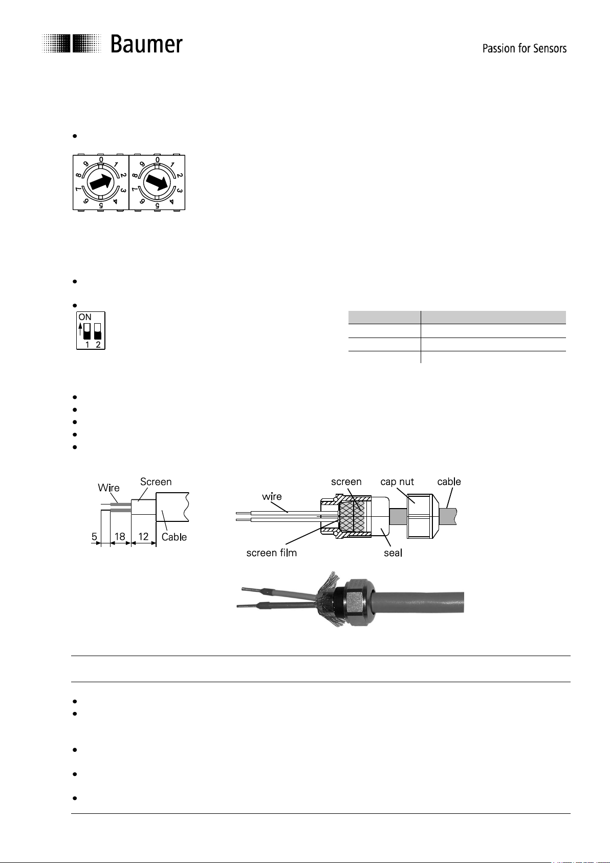
4.2.2. Setting the user address
Example: 23
both ON = final user
both OFF = all other users
Clamp
Resistance
A to GND
390 Ohm
B to +5 V
390 Ohm
A to B
220 Ohm
The user address is set decimally using the two rotary switches provided in the bus cover.
The maximum number of users is 99.
Decimal setting of the user address by the help of rotary switches 1 and 2 (default setting 00).
4.2.3. Terminating resistor
If the encoder is the final device in the bus line it is mandatory to terminate the bus by resistors. The resistors
are integrated in the bus cover and connected by means of a two-pole DIP switch.
The internal terminating resistors must be switched to „ON“ in case of final user by help of the 2-pole DIP
switch (default setting OFF). The two switches must always be set in the same direction.
4.2.4. Connecting the bus cover
Release the cap nut of the cable gland
Push the cap nut and seal insert with contact sleeve onto the cable sheath.
Strip the cable heath and cores, shorten the shield film where it exists (see fig.)
Bend over the braided shield by approx. 90°.
Push the sealing insert with contact sleeve along as far as the braided shield. Insert the sealing insert
with contact sleeve and cable flush into the cable gland and tighten the cap nut.
Take care that by no means the voltage supply is assigned to bus terminals A/B, this could damage
electronics components in the bus cover.
Avoid stub lines, especially with bus clocks greater than 1.5Mbit/s
Clamps with the same designation are internally connected to each other and identical in functionality.
Maximum load on the internal clamped connections UB-UB and GND-GND is 1 A each.
Signals A and B are decoupled at 100 nH inductivity each.
For voltage supply use cable gland 3 only. For the bus lines, either cable gland 1 or 2 may be used.
Please observe the admissible cable cross-sections.
Guide the cores the shortest way from the cable gland to the terminal connector. Observe the admissible
core-cross sections, use ferrules with flexible cores.
Avoid any crossings of data lines and supply line.
Manual_ProfibusDPV2_BIDE_EN.docx 9/41 Baumer IVO GmbH & Co. KG
22.11.12 Villingen-Schwenningen, Germany
Page 10
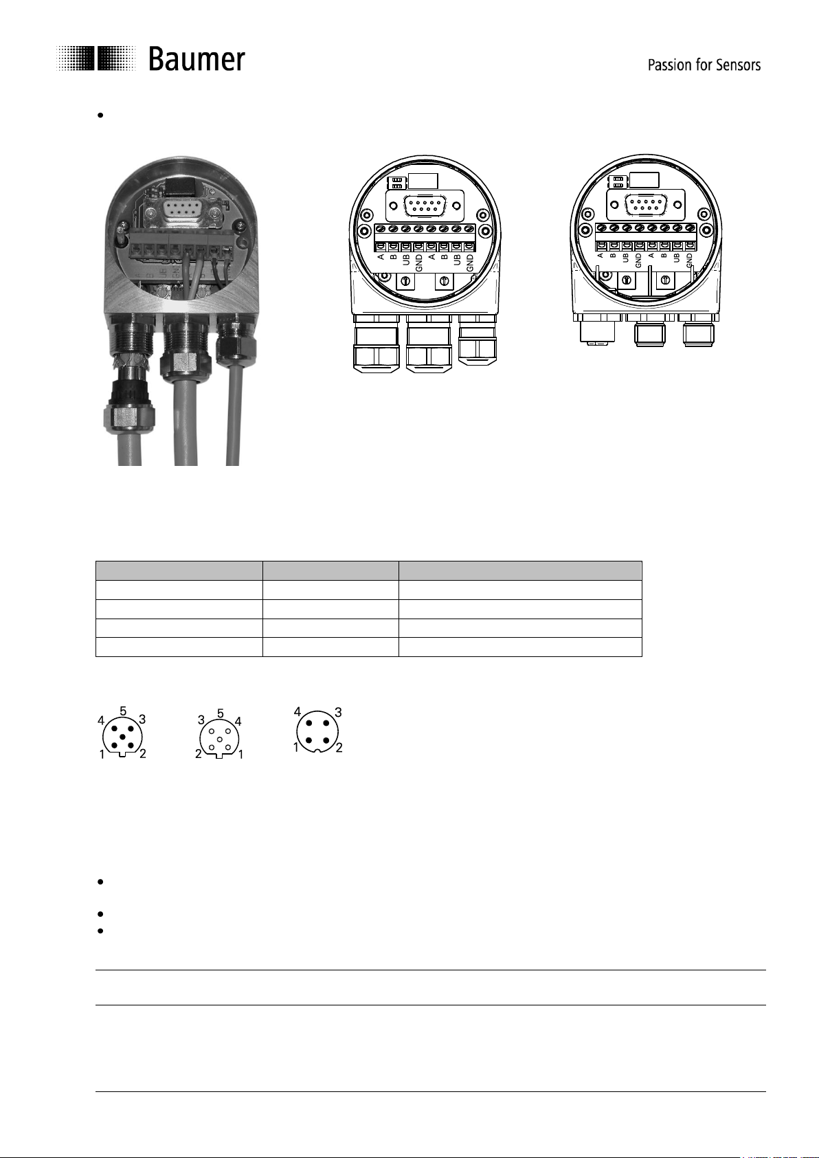
Seal up the unused cable gland using a sealing bolt (included in the delivery).
1 2 3
Cable gland
M12 connector
M12 connector
Clamp:
Significance
M12, 4 pins: Pin 1
UB
Supply voltage 10...30 VDC
M12, 4 pins: Pin 3
GND
Ground connection related to UB
M12, 5 pins: Pin 2
A
Negative serial data line
M12, 5 pins: Pin 4
B
Positive serial data line
M12 connector
for serial data lines
for voltage supply
male female
Terminal assignment
Clamps with the same designation are internally connected to each other and identical in function.
Maximum load on the internal clamped connections UB-UB and GND-GND is 1 A each.
Signals A and B are decoupled with an inductivity of 100 nH each.
Assembly of basic encoder and bus cover:
Carefully plug the bus cover onto the D-SUB connector of the basic encoder, then press it over the seal
taking care not to tilt it.
Tighten both fastening screws firmly in the same direction.
The bus cover must fully rest on the housing of the basic encoder and be firmly screwed on.
The encoder housing and braided shield of the connecting cable are only ideally connected if the bus cover is
resting fully on the basic encoder (positive locking).
Manual_ProfibusDPV2_BIDE_EN.docx 10/41 Baumer IVO GmbH & Co. KG
22.11.12 Villingen-Schwenningen, Germany
Page 11
5. Projecting
All examples in the present manual relate to SIEMENS® controls and the corresponding projecting software
Step7® , since they are commonly used as PROFIBUS controls. Please proceed in a corresponding way with
other controls.
5.1. Importing the GSD file
To implement the DP-Slave in the projecting software first the attached GSD file must be imported. All
required modifications of basic settings are implemented by parameterization (see “Parameterization”). The
GSD file itself is not modified.
Step7® software is imported in the hardware window („Extras – install GSD-files“). Prior to the import
operation the actual hardware project must be closed („Station - close“). Now the encoder appears at right in
the hardware catalogue under „PROFIBUS-DP“ – „More field devices“ – „Encoder“ – (xx corresponding to
the encoder type).
5.2. Encoder bus implementation
Use the mouse to drag text „GxxMW_H IsoM“ from the right out of the hardware catalogue to the bus bar. A
window pops up to enter the PROFIBUS node ID that must correspond to the settings of the BCD switch in
the bus cover. All other entries may remain unchanged. Close the entry by OK.
Use the mouse again to drag encoder module „telegram 81“ from the right out of the hardware catalogue to
plug-in position 1 of the module window at left below in the hardware window. Do not utilize the universal
module, this is not considered.
5.3. Assigning the user address
If not already done in a previous step or if required at a later date you may alter the PROFIBUS node ID of
the encoder. Upon a double click the window „Properties – DP-Slave“ pops up. Click on „PROFIBUS…“ and
enter the required node ID here. The node ID must correspond to the settings of the BCD switch in the bus
cover.
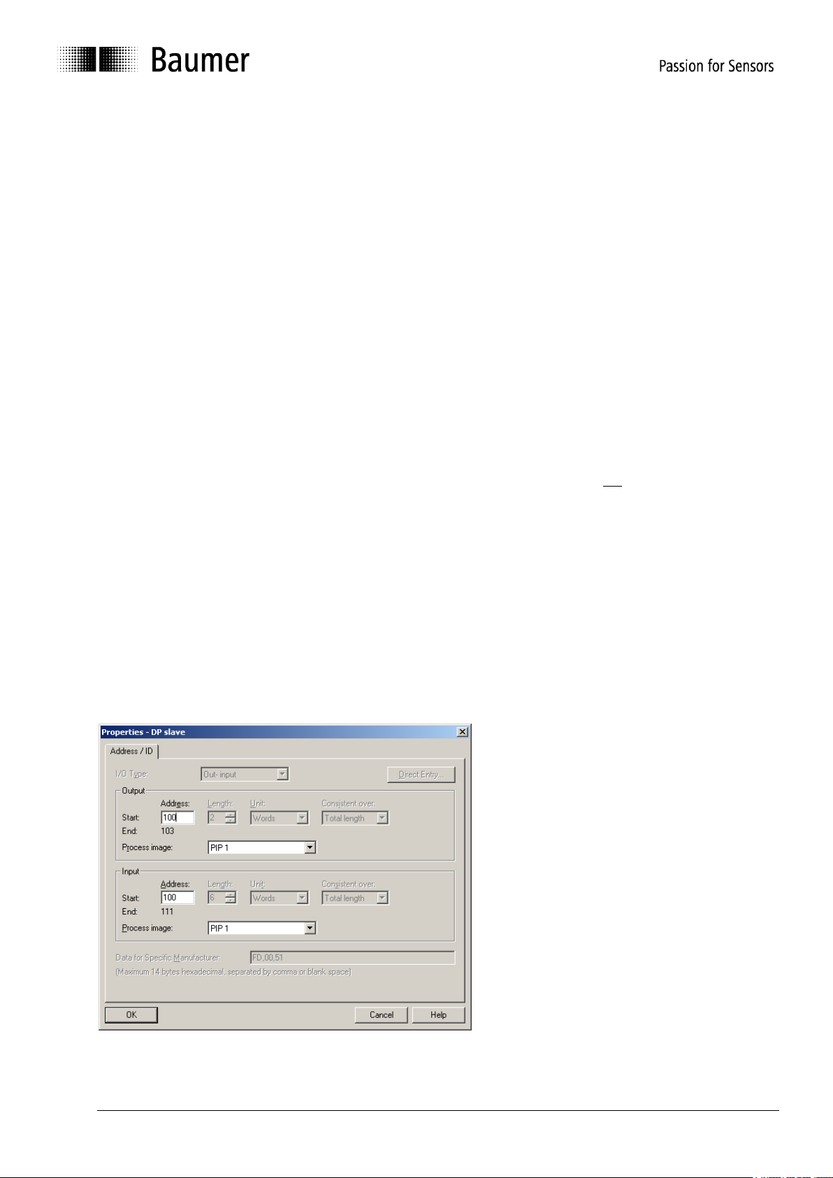
5.4. Assigning addresses for input and output data
Later access to encoder input and output data via master software requires assigning E/A addresses to the
input and output data. Click on the encoder icon on the bus bar HW config of Step7 to select the encoder.
Then double-click on module “telegram 81” (plug-in position 1) at left below. The window “Properties - DPslave” with tab “Address/ID” pops up (see screenshot).
Enter the respective initial addresses. It is admissible to use Identical or overlapping addresses for output and
input.
Manual_ProfibusDPV2_BIDE_EN.docx 11/41 Baumer IVO GmbH & Co. KG
22.11.12 Villingen-Schwenningen, Germany
Page 12
E/A fields require defining partial process images in clock-synchronous operation, in the example it is TPA1.
Take care that the selected partial process image comprises the initial address. If not it will result in an error
signal when interpreting the project.
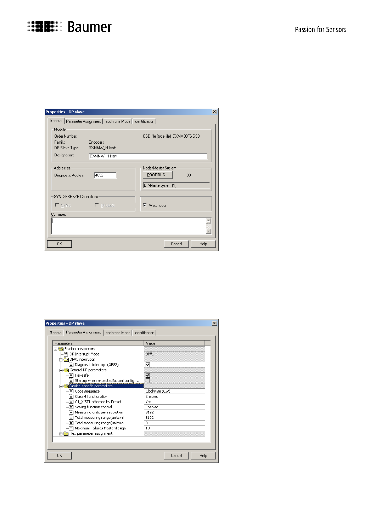
5.5. Parameterization
Upon double-click on the encoder icon at the bus bar, the window „Properties-DP-Slave“ pops up, showing
the tabs “General”, “Parameter Assignment” and “Clock synchronisation”.
5.5.1. General
System parameters under tab „General“ may usually be adopted without modifications.
If required, encoder name, diagnosis address and node ID under button „Profibus…” may be altered. Further
here is the option to deactivate the encoder’s response monitoring.
5.5.2. Parameter assignment
Manual_ProfibusDPV2_BIDE_EN.docx 12/41 Baumer IVO GmbH & Co. KG
22.11.12 Villingen-Schwenningen, Germany
Page 13

Device-specific parameters
Code sequence
Behaviour of the position data in relation to the sense of rotation of the encoder shaft when looking at
flange.
CW („clockwise“) = Ascending values with clockwise rotation
CCW („counter-clockwise“) = Ascending values with counter-clockwise rotation
Class 4 functionality
If active („enabled“), the encoder operates as a Class 4 Device of the encoder profile.
If not active ( „disabled), the encoder operates as a Class 3 Device of the encoder profile.
Here setting a preset is disabled.
G1_XIST1 affected by preset
If active (“Yes”), setting a preset will affect both the left-aligned position value G1_XIST1 and the
right-aligned position value G1_XIST2.
If not active (“No”), the left-aligned position value G1_XIST1 is not added an offset that is internally
calculated upon setting a preset. In this case, both position values G1_XIST1 and G1_XIST2 may be
different!
Scaling function control
If active (“enabled”), resolution („steps per revolution“, “measuring units per revolution”) and the total
measuring range can be parameterized at will within the admissible limits.
If not active (“disabled”), the previous encoder settings for resolution and total measuring range will
remain, i.e. the maximum limits. Any try to enter deviating parameters will result in a parameterization
error signal.
Measuring units per revolution
Parameterization of the required resolution („steps per revolution“, „measuring units per revolution“).
Admissible values range from 1 to the maximum encoder resolution. Usually the limits are indicated
in the parameterization software.
multivoPlus encoders require a 32 bit value here to get two input fields, i.e. „measuring units per
revolution (hi)“ and „(lo)“. Ho to split the 32 bit value into two 16 bit values please see under 8.1.4.
A re-parameterization may clear the previous offset value (see “note” under 6.6. Preset function).
Total measuring range (units)
Parameterization of the required total measuring range, „TMR“.
Singleturn encoders require here the same parameter as for the resolution (“Measuring units per
revolution“).
Admissible values range from 2 to the product of programmed resolution multiplied by maximum
number of revolutions. The maximum limit of the parameterization software is only applicable if the
resolution is also the maximum.
All multiturn encoders and multivoPlus singleturn encoders need a 32 bit value here to get two input
fields, „Total measuring range (units) hi“ and „lo“. How to split up the 32 bit value into two 16 bit
values please see under 8.1.4.
Any alteration of the total measuring range clears the previous offset value (see “note” under 6.6
Preset Function)
Manual_ProfibusDPV2_BIDE_EN.docx 13/41 Baumer IVO GmbH & Co. KG
22.11.12 Villingen-Schwenningen, Germany
Page 14

Important note for multiturn encoder operation
This encoder supports „Endless Operation“ automatically if required.
Thus, there are no special requirements for the encoder parameters “total measuring range” and
“measuring units per revolution” to stand in a certain ratio.
With endless operation active, the encoder shaft must not rotate when the encoder is not
powered. In those cases where powerless motion cannot be avoided, the encoder has to be
referenced (presetted) after each power-up. With Endless Operation inactive, the encoder shaft may
rotate unlimited when encoder not powered.
How to determine if „Endless Operation“ is in use:
Multiply the encoder’s „max. possible revolutions“ (depending on encoder 16 bit = 65536 or 13
bit = 8192) by your chosen parameter „measuring units per revolution“.
Divide this value by your chosen „total measuring range“.
If there is a division remainder, endless operation is in use.
Example for parameters without endless operation:
Maximum possible revolutions 65536 (16 bit multiturn)
Measuring units per revolution 3600
Total measuring range 29.491.200 (8192 x 3600)
Calculation: 65536 x 3600 / 29.491.200 = 8 (no remainder)
Example for parameters with endless operation:
Maximum possible revolutions 65536 (16 bit multiturn)
Measuring units per revolution 3600
Total measuring range 100.000
Calculation: 65536 x 3600 / 100.000 = 2359 remainder 29600
Maximum Failures Master lifesign
Designation of the maximum number of tolerated failures in master lifesign transmission in output
word STW2. Upon exceeding the number of tolerated failures an error signal is output in G1_XIST2
which has to be acknowledged.
Any monitoring of the Master lifesign will only take place respectively begin if the values transmitted
by the control in master lifesign are unequal to zero.
Hex parameterization
The hexadecimal data described only reflect the actual settings in the form they are transmitted to the
encoder and by no means should be altered in any way.
Manual_ProfibusDPV2_BIDE_EN.docx 14/41 Baumer IVO GmbH & Co. KG
22.11.12 Villingen-Schwenningen, Germany
Page 15

5.5.3. Clock synchronisation
Clock-synchronous operation is activated by a tick on “SynchronizeDP-Slave at equidistant DP-cycle“.
Time Ti marks the time before the equidistant bus clock (Global Control Message, GC) where the encoder is
sensing the position data with micro-second precision. It should be aimed at the smallest possible value.
250 µs minimum is admissible if encoder operation is without scaling, i.e. always with the maximum
resolution. For enabled scaling the minimum value is 375µs. In case several clock-synchronous DP-slaves
exist in the bus that require more time for data evaluation automatically the maximum value will be utilized.
Time To is insignificant to the encoder. Usually the projecting software makes a proposal under consideration
of correlations to other bus parameters.
Manual_ProfibusDPV2_BIDE_EN.docx 15/41 Baumer IVO GmbH & Co. KG
22.11.12 Villingen-Schwenningen, Germany
Page 16

Also in the encoder hardware configuration, under „Properties - DP-Slave“ – „PROFIBUS...“ – „Properties“ –
„Network settings“ – the “options” „Activate constant bus cycle time” and „Times Ti and To the same for all
slaves” must be ticked, otherwise the control may not perform the clock-synchronous operation.
5.6. Implementing the system functions for alarm handling
Make sure that the system components necessary for alarm handling have been implemented in the project.
With regard to Siemens Step7 projects there are in particular OB82 ("I/O Point Fault") and OB86 ("Loss Of
Rack Fault"). Missing these components will result in a control STOP in case of alarm.
5.7. Compilation and load of hardware and software configuration
After the complete hardware project configuration and once entered all parameters the project has to be
compiled and exported to the control.
Manual_ProfibusDPV2_BIDE_EN.docx 16/41 Baumer IVO GmbH & Co. KG
22.11.12 Villingen-Schwenningen, Germany
Page 17

6. Profibus operation
Colour
Status
LED yellow continuous
Encoder not active in the bus, not (yet) parameterized.
LED green continuous
Encoder in „Data_Exchange“ mode.
Active data exchange.
LED red continuous 2,5 s
Inadmissible position leap or the maximum electric speed is
exceeded
LED red flashing slowly (1 Hz)
Parameterization error
LED red flashing fast (5 Hz)
Transmitted preset value beyond the admissible value range
6.1. Master Class 1 (Parameterization master)
After encoder connection and start of master class 1 (parameterization master) PROFIBUS boots up
automatically. Based on the inactive status „Wait Prm“ (wait for parameterization) the encoder will go through
the operating statuses “Parameterization” and “Configuration” until the final status “Data Exchange” where it
usually remains.
6.2. Status indicator (multi-colour LED)
The back of the bus cover provides an integrated multi-colour LED indicating the encoder operating status.
When the encoder is under power supply, always one the following operation statuses is indicated by the
LED:
At encoder power on the LED remains yellow continuous until the PROFIBUS master (PLC) has begun data
communication with the slave (encoder). Usually this status is just an instant and nearly unnoticed since
normally the encoder is immediately tracked by master. However, yellow continuous may remain in case of
unsuccessful data communication, for example in case of an incorrect address or failure in the PROFIBUS
cable.
After successful encoder configuration and parameterization (automated process) the encoder goes to „Data
Exchange“ starting cyclic data communication. A green LED now signalizes cyclic transmission of position
data to the master.
Upon occurrence of a position leap („code consistency error“) or speed exceeding approx. 6200 rpm the LED
is red continuous for at least 2.5 s. If the indicated error remains or occurs repeatedly within this time, the red
continuous period is correspondingly extended.
If the encoder is transmitted a preset value outside the limits the LED will change to red flashing fast (5 Hz).
This status remains until the encoder receives an admissible preset value.
In case of inadmissible parameterization by master the LED is flashing red slowly (1 Hz) what may occur with
incorrect parameter input in the projecting phase. Most of incorrect inputs are compensated by the GSD file,
but it is impossible to eliminate every error.
Manual_ProfibusDPV2_BIDE_EN.docx 17/41 Baumer IVO GmbH & Co. KG
22.11.12 Villingen-Schwenningen, Germany
Page 18

6.3. Telegram 81 of profile PROFIdrive
ZSW2
15
14
13
12
11
10 9 8 7 6 5 4 3 2 1 0
Slave Sign-of-Life
0 0 0 0 0 0 0 0 0 0 0
0
G1_ZSW1
15
14
13
12
11
10 9 8 7 6 5 4 3 2 1 0
SE
PS
TA
PA
EA 0 0 0 0 0 0 0 0 0 0
0
G1_XIST1
31
0
encoder position (left-aligned) with / less preset offset
G1_XIST2
31
0
Encoder position (right-aligned) or error message
STW2
15
14
13
12
11
10 9 8 7 6 5 4 3 2 1 0
Master Sign-of-Life
0 0 0 0 0 0 0 0 0 0 0
0
G1_STW1
15
14
13
12
11
10 9 8 7 6 5 4 3 2 1 0
SEA
PS
TA
PR
REL 0 0 0 0 0 0 0 0 0 0
0
In line with PROFIBUS DP-V2 profile the encoder applies for cyclic communication in clock-synchronous
operation telegram81 of the PROFIdrive profile which means cyclic and clock-synchronous transmission of
12 bytes input data and 4 bytes output data.
Input data
There is a cyclic transmission of input data from encoder to control.
Bit SE: Sensor Error
If this bit is set, G1_XIST2 will come with an error code instead of the position value
Bit PS: Parking Sensor Active (Acknowledgement)
If this bit is set, the function „Parking Sensor“ will be enabled (error output suppressed)
Bit TA: Transmit absolute value cyclically (Acknowledgement)
If this bit is set, there will be cyclic position transmission in G1_XIST2.
This always applies to the present encoder.
Bit PA: Preset Acknowledgement
When this bit is set, the preset setting operation at the encoder was successful. The bit
mirrors the preset bit of the output data and is automatically taken back after reset.
Bit EA: Error Acknowledge Required
If this bit is set, an encoder error will have to be acknowledged. This is not general practice
with the present encoder (bit ever 0)
Position data are transmitted by both input double words G1_XIST1 and G1_XIST2. G1_XIST1
comprises the left-aligned position value, e.g. bit 31 = 1 as maximum position value (corresponding to
scaling). G1_XIST2 contains the right-aligned position value in the standard structure. G1_XIST2
further comprises an error code in case of error. The scaling operation always affects both double
words. The effect of the preset on position value G1_XIST1 can be eliminated by parameterization
(„G1_XIST1 affected by Preset“). In this case G1_XIST1 and G1_XIST2 show different position
values. G1_XIST2 is always affected by preset.
Output data
There is a cyclic transmission of output data to the encoder.
Bit SEA: Sensor Error Acknowledgement
If this bit is set, the error code in G1_XIST2 will be acknowledged what is not
not necessarily required with the present encoder.
Bit PS: Parking Sensor Active (acknowledgement)
It this bit is set, the function „Parking Sensor“ will be enabled (error output suppressed
Bit TA: Transmit absolute value cyclically (Acknowledgement)
If this bit is set, there will be a cyclic position transmission in G1_XIST2.
This ever applies to the present encoder, no matter if the bit is set or not.
Manual_ProfibusDPV2_BIDE_EN.docx 18/41 Baumer IVO GmbH & Co. KG
22.11.12 Villingen-Schwenningen, Germany
Page 19

Bit PR: Preset
Value
Error
Significance
0x0001
Position error
Presently the encoder cannot provide a
correct position
0x0F01
Unknown command
In G1_STW1 the master has transmitted a
command which is unknown to the encoder
0x0F02
Sign-of-Life error (Master)
Number of admissible failures in the mastersign-of-life has been exceeded
0x0F04
Synchronisation error
Number of admissible failures in the bus
cycle signal has been exceeded
If bit PR is set, the preset operation will be enabled. Once the Preset Acknowledge bit of the
input data is set, bit PR should be reset.
Bit REL: Preset Relative
If this bit is set, the function Preset Relative will be enabled, e.g. the actual position is added
the preset value as offset (negative values as complement on two). If this bit is not set, the
preset operation will be absolute. In other words, the encoder position is set to the preset
value.
6.4. Position readout
Position data are transmitted by telegram81 of the PROFIdrive profile as described above. Control access to
the data should only be enabled during clock-synchronous alarm. Only then it is guaranteed that the encoder
position is derived from the desired clock-synchronous bus cycle.
By principle, there could also be a direct control access to the parameterized I/O address using the peripheral
input words. We strongly recommend to refrain from this in clock-synchronous operation, since in this case
consistency and clock synchrony are not ensured.
6.5. Error signals in G1_XIST2
Bit 15 in G1_ZSW1 means that the value in G1_XIST2 is not a position value but an error code. Should
several errors occur at the same time only the first one will be transmitted.
6.6. Preset function
Preset default setting is 0. Preset alteration is enabled by acyclic parameter 65000. The value is saved
volatile, i.e. it is lost at encoder power off. For non-volatile saving utilize parameter 971.
The actual preset operation is triggered by output word „G1_STW1“ bit 12. A feedback after a successful
operation is given by input word „G1_ZSW1“, bit12. This bit remains until the control will reset the
corresponding bit in the output word.
The preset value (volatile) must not be confused with the internal preset offset (non-volatile). The preset-
offset is automatically saved in the non-volatile memory so that the encoder will be in the same position after
power off and at power on.
The preset effect on position value G1_XIST1 can be compensated by parameterization („G1_XIST1 affected
by Preset“). In this case G1_XIST1 and G1_XIST2 provide different position values. G1_XIST2 is always
affected by preset.
Upon performing a preset operation an internal offset value is calculated and immediately saved non-volatile
in EEPROM. EEPROM provides 1 million writing cycles, however, frequent software or event-triggered preset
operations can exhaust the service life despite this high number of writing cycles. This should be considered
in the control software layout.
Manual_ProfibusDPV2_BIDE_EN.docx 19/41 Baumer IVO GmbH & Co. KG
22.11.12 Villingen-Schwenningen, Germany
Page 20

Note:
Data Unit:
Value
Significance
Octet 1
Station_status_1
Diverse bits, see PROFIBUS literature (e.g. Ext. Diagnose
Bit)
Octet 2
Station_status_2
Diverse bits, see PROFIBUS literature (e.g. Stat. Diagnose
Bit)
Octet 3
Station_status_3
External diagnosis overflow bit
Octet 4
Diag_Master_Add
Master address after parameterization (otherwise 0xFF)
Octet 5
Ident_Number
Ident number high byte
Octet 6
Ident_Number
Ident number low byte
Octet 7
Block Length
0x07
Following block length in bytes (including this one)
Octet 8
Alarmtyp
0x01
1 = Diagnostic alarm
Octet 9
Slot
0x01
Slot number
Octet 10
Alarm Spec
xx
Alarm Specifier (in / out) and sequence number (0..31)
Octet 11
Header
0x81
see DPV2 encoder profile
Octet 12
Channel
0x40
see DPV2 encoder profile
Octet 13
Type of Diagnosis
0x16
see DPV2 encoder profile / Alarm definition
At altering the encoder’s total measuring range during re-parameterization the internal preset-offset-value will
be cleared. This is insignificant for the application since in this case the relation to the position gets lost
anyway. The preset value saved by parameter 971 will of course remain. It must be ensured however that the
former preset value is within the new total measuring range, otherwise a new value has to be stored.
6.7. Alarms
Diagnosis alarms are triggered in line with acyclic services according to DPV1.
A diagnosis alarm is triggered upon the encoder having detected a probably incorrect position. The next
position data telegram is added a high priority bit in the function code (bit 1) by the encoder what makes the
control transmit a acyclic diagnosis alarm request. The encoder responds by an acyclic diagnosis telegram.
“Data Unit” (DU) of this telegram provides the following structure: Octets 1 to 6 correspond to the diagnosis
telegram of cyclic data exchange.
The alarm is acknowledged by the control under reference to the running alarm sequence number.
The encoder will only consider value 22 (0x16) indicating a position error as „Type of Diagnosis / Alarm
Definition).
A diagnosis alarm is triggered once with each inbound and outbound event. An outbound event alarm
comprises an „Alarm Specifier“ for „outbound event“ together with a specific sequence number that is
incremented towards the inbound event.
Siemens controls proceed diagnosis OB82 in case of alarm. If this is not implemented in the project the
control will go to STOP in case of alarm.
Alarms resulting from a probably incorrect position can be signalized in three different ways:
DPV1 Diagnosis alarm (as described)
Error signal in G1_XIST2 (see under „Error signals in G1_XIST2“)
LED in the bus cover is red continuous for at least 2.5 s
Manual_ProfibusDPV2_BIDE_EN.docx 20/41 Baumer IVO GmbH & Co. KG
22.11.12 Villingen-Schwenningen, Germany
Page 21

6.8. Warnings
Called parameter
Value
Example
ID
Slot no.1 (E/A address telegram81)
Slot no.0 (diagnisos address slave)
0x0200
0xFFD
Index
47 = 0x2F
255 = 0xFF
0x2F
0xFF
Length
Length of data to be exported out of
the data block (write)
0x0A
Byte
Significance
Explanation
Example
0
Request Reference
Selectable at will by master, mirrored
in response
0xAA
1
Request ID
Request=1 Change=2
0x01
2
Shaft no.
0= whole slave
0x00
3
Number of parameters
Only one parameter: 1
0x01
4
Attribute
0x10=Value = 0x20=Description
0x30=Text
0x10
5
Number of parameter elements
Several elements (Sub-IDs) during
read/write, counted from Sub-ID
0x04
6
Prm_no hi
High byte of parameter number,
in the example 65000=$FDE8
0xFD
7
Prm_no lo
Low byte of parameter number
0xE8
8
Subindex hi
0x00
9
Subindex lo
0x02
Supplementary bytes 10...15 only with “Change Parameter”:
A diagnostic warning is triggered upon the encoder recognizing that specific internal tolerance limits have
been achieved. Conversely to alarms a warning does not consequently mean a position error.
The process sequence of a diagnostic warning is fully identical to that of a diagnosis alarm described in the
above. The difference is made in „Type of Diagnosis“ defining several reasons for warning.
Type of diagnosis:
16 (0x10): “Frequency exceeded” (threshold signal when exceeding the maximum encoder
speed)
17 (0x11): „Light Control“ (threshold signal for being at the infrared LED regulating limit)
20 (0x14): “Battery Voltage Low” (threshold signal for low battery voltage)
6.9. Acyclic data communication according to DPV1
6.9.1. Overview
The parameterization master utilizes acyclic telegrams in line with PROFIBUS-DPV1 to read and if required
to write addressed data in the DP slave by slot, index and parameter number. Prior condition is that the DP
slave is in Data Exchange mode.
Acyclic data communication utilizes system functions DS_Read and DS_Write. DS_Write is appropriate for
writing parameters („Change Parameter“).
A parameter reading operation by DS_Read („Request Parameter“) is always preceded by DS_Write
supplying the slave with all necessary information on the requested parameter read access. Successful exit
of DS_Write may take several bus cycles, afterwards DS_Read can be launched.
6.9.2. DS_Write
SIEMENS controls apply system function SFB53 / WRREC for DS_Write. Parameters to be delivered are
among others index and ID (Slot), “Index=47” as encoder profile parameter, Index=255“ for I&M parameters.
The slot address is the “ID”. For Slot1 it is the programmed E/A address of telegram 81, in the examples
below 512 = 0x200. Slot0 is addressed via the diagnosis address of the DP-Slaves, in the examples below
4093 = 0xFFD.
An additional data block must be prepared for accommodating more parameters. The schematic structure of
this data block is described in the following. Length depending on read/ write access and parameter length
are between 10 and 16 bytes.
DS_WRITE
Data block (write)
Manual_ProfibusDPV2_BIDE_EN.docx 21/41 Baumer IVO GmbH & Co. KG
22.11.12 Villingen-Schwenningen, Germany
Page 22

10
Format of the following parameter
0x40=Zero 41=Byte 42=Word
43=Dword 44=Error
0x43
11
Number of parameter values
Encoder: ever “1”
0x01
12
Value
with byte: Parameter
with word: Parameter Hi Byte (MSB)
with Dword: Parameter Byte 3 (MSB)
0x00
13
Value
with Word: Parameter Lo Byte (LSB)
with Dword: Parameter Byte 2
0x01
14
Value
with Dword: Parameter Byte 1
0x00
15
Value
with Dword: Parameter Byte 0 (LSB)
0x00
Called parameter
Value
Example
ID
Slot no.1 (E/A address telegram81)
Slot no.0 (diagnosis address slave)
0x0200
0xFFD
Index
47 = 0x2F
255 = 0xFF
0x2F
0xFF
Length
Maximum length of data to be
transmitted that can be imported in
data block
0x40
Byte
Significance
Explanation
Example
0
Request Reference
Mirrored value out of DS_Write
0xAA
1
Response ID
0x01 = Request parameter (success)
0x02 = Change parameter(success)
0x81 = Request parameter(error)
0x82 = Change parameter(error)
0x01
2
Shaft no.
always 0= whole slave
0x00
3
Number of parameters
Only one parameter: 1
0x01
4
Format
0x01 = Boolean
0x02 = Integer8
0x03 = Integer16
0x04 = Integer32
0x05 = Unsigned8
0x06 = Unsigned16
0x07 = Unsigned32
0x08 = FloatingPoint
0x09 = VisibleString
0x10 = OctetString
0x10
5
Number of values
0xnn
6
Value 1
7
Value 2
8
Value 3
9
Value n
6.9.3. DS_Read
Controls by SIEMENS apply system function SFB52 / RDREC for DS_Read. Index and ID (Slot) parameters
correspond to those of DS_Write. Parameter MLEN corresponds to the size of the import data block. It may
always remain the maximum amount (for example 64).
An additional data block of sufficient capacity must be provided to accommodate the imported data. A volume
of 68 byte is sufficient for parameters implemented in the encoder. Its content according to DS_Read is
described in the following.
DS_READ
Data block (read)
The following acyclic functional parameters of the PROFIdrive profile V3.3 (parameter numbers 9xx)
respectively of DPV2 encoder profile V3.2 (65xxx) are supported by GXMMW:
Manual_ProfibusDPV2_BIDE_EN.docx 22/41 Baumer IVO GmbH & Co. KG
22.11.12 Villingen-Schwenningen, Germany
Page 23

Parameter 918 (read only) Profibus node ID (BCD switches)
Called parameter
Value
Example
Function ID
Permanent for DS_Write
0x5F
ID
Slot no.1 (E/A address telegram81)
0x0200
Index
47 = 0x2F
0x2F
Length
10 = 0x0A
0x0A
Byte #
Example
0
Request Reference (Example)
0xAA
1
Request ID=0x01 Change ID=0x02
0x01
2
Shaft no. (0=whole device)
0x00
3
Number of parameters
0x01
4
Attribute = “Value”
0x10
5
Number of parameter elements
0x01
6
Prm_no hi: 918 = 0x0396
0x03
7
Prm_no lo: 918 = 0x0396
0x96
8
Subindex hi
0x00
9
Subindex lo
0x00
Called parameter
Value Function ID
Permanent for DS_Read
0x5E
ID
Slot no.1 (E/A address telegram81)
0x0200
Index
47 = 0x2F
0x2F
Max.length
64 = 0x40
0x40
Byte #
Example
0
Request Reference: mirrored
0xAA
1
Request ID (not: Change)
0x01
2
Shaft no. (0=whole device)
0x00
3
Number of parameters
0x01
4
Format: Unsigned16
0x06
5
Number of values
0x01
6
Value (hi): ever 0
0x00
7
Value (lo): Node address
0x37
Parameter 922 (read only) Telegram type (=81)
Parameter 964 (read only) Device identification
Parameter 965 (read only) Profile number (3.2)
Parameter 971 (read/write) Transfer to non-volatile memory
Parameter 979 (read only) Sensor format
Parameter 65000 (read/write) Preset value
All parameters are accessed by Slot 1 (indicate E/A address under „ID“ in Step7), index 47 and subindex 0.
Additional access to block 0 of I&M functions (Identification and Maintenance ) via index 255, Slot 0 or 1,
parameter 65000.
6.9.4. PROFIdrive parameter 918 PROFIBUS node ID
Readout of the PROFIBUS node ID (BCD switch). Example node ID: 55 (0x37)
DS_WRITE
DP-V1 Header
Data Unit - (write):
DS_READ
DP-V1 Header
Data Unit - (read):
Manual_ProfibusDPV2_BIDE_EN.docx 23/41 Baumer IVO GmbH & Co. KG
22.11.12 Villingen-Schwenningen, Germany
Page 24

6.9.5. PROFIdrive parameter 922 telegram type
Called parameter
Value
Example
Function ID
Permanent for DS_Write
0x5F
ID
Slot no.1 (E/A address telegram81)
0x0200
Index
47 = 0x2F
0x2F
Length
10 = 0x0A
0x0A
Byte #
Example
0
Request Reference (example)
0xAA
1
Request ID=0x01 Change ID=0x02
0x01
2
Shaft no. (0=whole device)
0x00
3
Number of parameters
0x01
4
Attribute = “Value”
0x10
5
Number of parameter elements
0x01
6
Prm_no hi: 922 = 0x039A
0x03
7
Prm_no lo: 922 = 0x039A
0x9A
8
Subindex hi
0x00
9
Subindex lo
0x00
Called parameter
Value Function ID
Permanent for DS_Read
0x5E
ID
Slot No.1 (E/A address telegram81)
0x0200
Index
47 = 0x2F
0x2F
Max.Length
64 = 0x40
0x40
Byte #
Example
0
Request Reference: mirrored
0xAA
1
Request ID (not: Change)
0x01
2
Shaft no. (0=whole device)
0x00
3
Number of parameters
0x01
4
Format: Unsigned16
0x06
5
Number of values
0x01
6
Value (hi): ever 0
0x00
7
Value (lo): telegram no.
0x51
Readout of the telegram type. The DPV2 encoder applies always telegram 81 (0x51).
DS_WRITE
DP-V1 Header
Data Unit - (write):
DS_READ
DP-V1 Header
Data Unit - (read):
Manual_ProfibusDPV2_BIDE_EN.docx 24/41 Baumer IVO GmbH & Co. KG
22.11.12 Villingen-Schwenningen, Germany
Page 25

6.9.6. PROFIdrive parameter 964 device ID
Called parameter
Value
Example
Function ID
Permanent for DS_Write
0x5F
ID
Slot no.1 (E/A address/telegram81)
0x0200
Index
47 = 0x2F
0x2F
Length
10 = 0x0A
0x0A
Byte #
Example
0
Request Reference (Example)
0xAA
1
Request ID=0x01 Change ID=0x02
0x01
2
Achse Nr. (0=whole device)
0x00
3
Number of parameters
0x01
4
Attribute = “Value”
0x10
5
Number of parameter elements
0x01
6
Prm_no hi: 964 = 0x03C4
0x03
7
Prm_no lo: 964 = 0x03C4
0xC4
8
Subindex hi
0x00
9
Subindex lo
0x00
Called parameter
Value Function ID
Permanent for DS_Read
0x5E
ID
Slot no.1 (E/A address telegram81)
0x0200
Index
47 = 0x2F
0x2F
Max.Length
64 = 0x40
0x40
Byte #
Example
0
Request Reference: mirrored
0xAA
1
Request ID (not: Change)
0x01
2
Shaft no. (0=whole device)
0x00
3
Number of parameters
0x01
4
Format: Array of U16
0x06
5
Number of values
0x05
6
Manufacturer ID Baumer IVO=012A
0x01
7
(LSB)
0x2A
8
Device Type (Manufacturer specific)
0x00
9
(LSB)
0x00
10
Firmware Version e.g. V1.00
0x10
11
(LSB)
0x00
12
Firmware date (year), e.g. 2007
0x07
13
(LSB)
0xD7
14
Firmware date (day) , e.g. 17
0x11
15
Firmware date (month), e.g. 09
0x09
Readout of the device ID (device identification data). This data block provides information on manufacturer,
device name, firmware version and firmware date. This information can be called up individually utilizing the
sub indexes.
DS_WRITE
DP-V1 Header
Data Unit - (write):
DS_READ
DP-V1 Header
Data Unit - (read):
Manual_ProfibusDPV2_BIDE_EN.docx 25/41 Baumer IVO GmbH & Co. KG
22.11.12 Villingen-Schwenningen, Germany
Page 26

6.9.7. PROFIdrive parameter 965 profile number
Called up
parameter
Value
Example
Function ID
Permanent for DS_Write
0x5F
ID
Slot no.1 (E/A address telegram81)
0x0200
Index
47 = 0x2F
0x2F
Length
8 = 0x08
0x08
Byte #
Example
0
Request Reference (example)
0xAA
1
Request ID=0x01 Change ID=0x02
0x01
2
Shaft no. (0=whole device)
0x00
3
Number of parameters
0x01
4
Attribute = “Value”
0x10
5
Number of parameter elements
0x01
6
Prm_no hi: 965 = 0x03C5
0x03
7
Prm_no lo: 965 = 0x03C5
0xC5
Called parameter
Value Function ID
Permanent for DS_Read
0x5E
ID
Slot no.1 (E/A address telegram81)
0x0200
Index
47 = 0x2F
0x2F
Max.Length
64 = 0x40
0x40
Byte #
Example
0
Request Reference: mirrored
0xAA
1
Request ID
0x01
2
Shaft no. (0=whole device)
0x00
3
Number of parameters
0x01
4
Format: Unsigned16
0x06
5
Number of values
0x01
6
Profile number (hi)
0x03
7
Profile number (lo)
0x02
Readout of the profile number. The encoder relates to the DPV2 encoder profile (PNO Order Nr 3.162),
version V3.2 of December 2004. For this reason the value replied is ever 0x03, 0x02.
DS_WRITE
DP-V1 Header
Data Unit - (write):
DS_READ
DP-V1 Header
Data Unit - (read):
Manual_ProfibusDPV2_BIDE_EN.docx 26/41 Baumer IVO GmbH & Co. KG
22.11.12 Villingen-Schwenningen, Germany
Page 27

6.9.8. PROFIdrive parameter 971 transfer to non-volatile memory
Called parameter
Value
Example
Function ID
Permanent for DS_Write
0x5F
ID
Slot no.1 (E/A address telegram81)
0x0200
Index
47 = 0x2F
0x2F
Length
10 = 0x0A
0x0A
Byte #
Example
0
Request Reference (example)
0xAA
1
Request ID=0x01 Change ID=0x02
0x01
2
Shaft no. (0=whole device)
0x00
3
Number of parameters
0x01
4
Attribute = “Value”
0x10
5
Number of parameter elements
0x01
6
Prm_no hi: 971 = 0x03CB
0x03
7
Prm_no lo: 971 = 0x03CB
0xCB
8
Subindex hi
0x00
9
Subindex lo
0x00
10
Format Word
0x06
11
Number of values
0x01
12
Save command (MSB)
0x00
13
Save command (LSB)
0x01
Called parameter
Value Function ID
Permanent for DS_Read
0x5E
ID
Slot no.1 (E/A address telegram81)
0x0200
Index
47 = 0x2F
0x2F
Max.Length
64 = 0x40
0x40
Byte #
Example
0
Request Reference: mirrored
0xAA
1
Request ID (not: Change)
0x01
2
Shaft no. (0=whole device)
0x00
3
Number of parameters
0x01
4
Format: Unsigned16
0x06
5
Number of values
0x01
6
Value (hi): ever 0
0x00
7
Value (lo): ever 0
0x00
By calling this parameter all volatile parameter are stored into the encoder’s non-volatile memory. At the
present DPV2 encoder this procedure relates only to the preset value (profile parameter 65000). The saving
operation is performed in DS_WRITE.
DS_WRITE
DP-V1 Header
Data Unit - (write):
DS_READ
DP-V1 Header
Data Unit - (read):
Manual_ProfibusDPV2_BIDE_EN.docx 27/41 Baumer IVO GmbH & Co. KG
22.11.12 Villingen-Schwenningen, Germany
Page 28

6.9.9. PROFIdrive parameter 979 sensor format
Called parameter
Value
Example
Function ID
Permanent for DS_Write
0x5F
ID
Slot no.1 (E/A address telegram81)
0x0200
Index
47 = 0x2F
0x2F
Length
10 = 0x0A
0x0A
Byte #
Example
0
Request Reference (example)
0xAA
1
Request ID=0x01 Change ID=0x02
0x01
2
Shaft no. (0=whole device)
0x00
3
Number of parameters
0x01
4
Attribute = “Value”
0x10
5
Number of parameter elements
0x06
6
Prm_no hi: 979 = 0x03D3
0x03
7
Prm_no lo: 979 = 0x03D3
0xD3
8
Subindex hi
0x00
9
Subindex lo
0x00
Readout of data block „Sensor Format“. The data block informs on sensor parameters as sensor type,
programmed singleturn resolution, shift factor for G1_XIST1 and G1_XIST2 as well as the number of possible
turns (multiturn encoders). This information can also be called up individually utilizing the sub indexes.
The example shows how to call all elements of an encoder with a parameterized resolution of 8192
steps/revolution, revolution counter 65536 revs. (in this case 0xFFFF). Left-aligned display in G1_XIST1 by
shift factor =3.
DS_WRITE
DP-V1 Header
Data Unit - (write):
Manual_ProfibusDPV2_BIDE_EN.docx 28/41 Baumer IVO GmbH & Co. KG
22.11.12 Villingen-Schwenningen, Germany
Page 29

DS_READ
Called parameter
Value Function ID
Permanent for DS_Read
0x5E
ID
Slot no.1 (E/A address telegram81)
0x0200
Index
47 = 0x2F
0x2F
Max.Length
64 = 0x40
0x40
Byte #
Example
0
Request Reference: mirrored
0xAA
1
Request ID (not: Change)
0x01
2
Shaft no. (0=whole device)
0x00
3
Number of parameters
0x01
4
Format: Array of U32
0x07
5
Number of values
0x06
6
Header Prm.979 lt. Profidrive Profile
0x00
7
0x00
8
0x51
9
0x11
10
Sensor Type lt. Profidrive Profile (fix)
0x80
11
0x00
12
0x00
13
0x02
14
param. steps per revolution (MSB)
0x00
15
0x00
16
0x20
17
(LSB)
0x00
18
shift factor” for G1_XIST1 (MSB)
0x00
19
0x00
20
0x00
21
(LSB)
0x03
22
shift factor” for G1_XIST2 (MSB)
0x00
23
0x00
24
0x00
25
(LSB)
0x00
26
number of revolutions (MSB)
0x00
27
0x00
28
0xFF
29
(LSB)
0xFF
DP-V1 Header
Data Unit - (read):
Manual_ProfibusDPV2_BIDE_EN.docx 29/41 Baumer IVO GmbH & Co. KG
22.11.12 Villingen-Schwenningen, Germany
Page 30

6.9.10. Profile parameter 65000 preset value
Called parameter
Value
Example
Function ID
fix für DS_Write
0x5F
ID
Slot-Nr.1 (E/A address telegram81)
0x0200
Index
47 = 0x2F
0x2F
Length
8= 0x08
0x08
Byte #
Example
0
Request reference (example)
0xAA
1
Request ID=0x01 Change ID=0x02
0x01
2
Shaft no. (0=whole device)
0x00
3
Number of parameters
0x01
4
Attribute = “Value”
0x10
5
Number of parameter elements
0x01
6
Prm_no hi: 65000 = 0xFDE8
0xFD
7
Prm_no lo: 65000 = 0xFDE8
0xE8
Called parameter
Value Function ID
Permanent for DS_Read
0x5E
ID
Slot no.1 (E/A address telegram81)
0x0200
Index
47 = 0x2F
0x2F
Max.Length
64 = 0x40
0x40
Byte #
Example
0
Request reference: mirrored
0xAA
1
Request ID=0x01 Change ID=0x02
0x01
2
Shaft no. (0=whole device)
0x00
3
Number of parameters
0x01
4
Format: Unsigned32
0x07
5
Number of values
0x01
6
Preset value (hi byte)
0xXX
7
Preset value
0xXX
8
Preset value
0xXX
9
Preset value (lo byte)
0xXX
This parameter is to read or write the preset value the encoder is set to upon having accomplished the preset
command using output data word G1_STW1, bit „PR“. The preset value is not automatically saved (see
parameter 971 to save).
Note:
It goes without saying that the absolute encoder position will remain also during power off and at power on,
even if the encoder received a preset command before.
DS_WRITE
DP-V1 Header
Data Unit - (write):
DS_READ
DP-V1 Header
Data Unit - (read):
Manual_ProfibusDPV2_BIDE_EN.docx 30/41 Baumer IVO GmbH & Co. KG
22.11.12 Villingen-Schwenningen, Germany
Page 31

6.9.11. I&M parameter 65000 block 0
Called parameter
Value
Example
Function ID
Permanent for DS_Write
0x5F
ID
Slot 0 (diagnosis address DP-Slave)
0x0FFD
Index
255 = 0xFF
0xFF
User data length
4 = 0x04
0x04
Example
EXTENDED_
FUNCTION_NUM
0x08 permanent for CALL
0x08
reserved
ever 0x00
0x00
IM_INDEX (hi)
65000 = 0xFDE8
0xFD
IM_INDEX (lo)
65000 = 0xFDE8
0xE8
Called parameter
Value
Example
Function ID
Permanent for DS_Read
0x5E
ID
Slot 0 (Diagnose-Adresse DP-Slave)
0x0FFD
Index
255 = 0xFF
0xFF
Usere data length
68 = 0x44 max.
0x40
Example
EXTENDED_
FUNCTION_NUM
0x08 permanent for CALL
0x08
reserved
ever 0x00
0x00
IM_INDEX (hi)
65000 = 0xFDE8
0xFD
IM_INDEX (lo)
65000 = 0xFDE8
0xE8
Byte #
Example
0...9
Header
0x00
10
I&M Block
MANUFACTURER_ID
0x01
11
MANUFACTURER_ID
0x2A
12...31
ORDER_ID (20)
0x20
32...47
SERIAL_NUMBER (16)
0x20
48
HARDWARE_REVISION
0x00
49
HARDWARE_REVISION
0x00
50
SOFTWARE_REVISION (*4)
0x56 = ‘V’
51
SOFTWARE_REVISION
0x31 = ‘1’
I&M is a concept for uniform identification of field devices and is neither manufacturer nor industry-specific.
For this purpose, the field device provides particular information on an electronic product label.
Readout of block 0 of I&M functions (I&M0) is in line with PROFIBUS Identification & Maintenance Guideline
3502 and DPV2 encoder profile 3162. Data blocks I&M1 to I&M4 are not implemented.
I&M functions are accessed by Slot 0 or Slot 1 and index 255. Access to block I&M0 is by parameter number
65000 (0xFDE8).
Slot 0 of SIEMENS controls is addressed by the diagnosis address of the DP slave, in the example below
4093 (0x0FFD).
DS_WRITE
DP-V1 Header
Data Unit - Call Header (read):
DS_READ
DP-V1 Header
Data Unit - Call Header (read):
Data Unit - Body (read):
Manual_ProfibusDPV2_BIDE_EN.docx 31/41 Baumer IVO GmbH & Co. KG
22.11.12 Villingen-Schwenningen, Germany
Page 32

52
SOFTWARE_REVISION
0x30 = ‘0’
53
SOFTWARE_REVISION
0x30 = ‘0’
54
REVISION_COUNTER
0x00
55
REVISION_COUNTER
0x00
56
PROFILE_ID (*2)
0x3D
57
PROFILE_ID
0x00
58
PROFILE_SPECIFIC_TYPE
0x00
59
PROFILE_SPECIFIC_TYPE
(*1)
60
IM_VERSION
0x01
61
IM_VERSION
0x01
62
IM_SUPPORTED
0x00
63
IM_SUPPORTED
0x01
(*1) 0x00 for singleturn encoders; 0x01 for multiturn encoders
(*2) 0x3D00 permanent for DPV2 encoder profile
(*3) 0x012A manufacturer ID of Baumer IVO GmbH & Co. KG
(*4) ‘V’(ersion,official),’R’(evision),’P’(rototype),’U’(nder Field Test) or ‘T’(est Device)
Manual_ProfibusDPV2_BIDE_EN.docx 32/41 Baumer IVO GmbH & Co. KG
22.11.12 Villingen-Schwenningen, Germany
Page 33

7. System documentation: Profibus-DP
7.1. General information
PROFIBUS is a manufacturer-unspecific open communication system for applications in the fields of
production, process and building automation. It is broken down into three variants:
PROFIBUS FMS for data communication between control units on the production and process
management level.
PROFIBUS PA for process engineering applications.
PROFIBUS DP for fast data exchange between control units and decentralized peripherals in process
automation.
PROFIBUS-DP is characterized by the following properties:
Short response times (1 ms with 32 users and 12 MBaud)
Reliable transmission procedure (Hamming distance 4)
Availability of a wide range of standardized system components
Good diagnostic capability
Simple handling and facility for upgrading
User-oriented bus system
Open system
PROFIBUS-DP ist standardized by EN 50170 Vol. 2 defining communication and user profiles. To clocksynchronous encoders applies „Profile for DP-V2 Encoders Version 3.2, Order No: 3.162“ in the respective
actual amendment.
The profile differs by the number of supported functions according to device class 3 and 4. Device class 4
comprises functional extensions and all functions of class 3. Parameterization and preset functions are only
supported by class 4. The product supports classes 3 and 4.
7.2. GSD file
The device master data file (GSD file) describes all encoder data required for operation. Format and content
are defined by standard EN 50170.
The GSD file provides ident number 09F6 for all encoders described. The GSD file is an essential
configuration tool for encoder parameterization and configuration.
The GSD file provides two kinds of information:
General information such as manufacturer’s name, product designation, ident number, PROFIBUS -
specific parameters and Baud rates.
Application-relevant information such as configuration options, parameters, parameter descriptions,
hardware and software status and diagnostic possibilities.
Manual_ProfibusDPV2_BIDE_EN.docx 33/41 Baumer IVO GmbH & Co. KG
22.11.12 Villingen-Schwenningen, Germany
Page 34

7.3. Encoder operating parameters
Parameter
Significance
Sense of rotation
Behaviour of the output code relating to the shaft’s sense of rotation when looking at
the flange.
CW („clockwise“) = ascending values with clockwise rotation
CCW („counter-clockwise“) = ascending values with counter-clockwise rotation
Resolution
(„Measuring units
per revolution“)
Number of steps per revolution, input in integral steps
Measuring range
(„Total Measuring
Range“)
Total resolution = number of steps per revolution x number of revolutions,
input in integral steps
Steps
The actual encoder position is assigned to a certain position value (referencing)
Parameter
Value range
Default setting
Data type
Sense of rotation
CW/CCW
CW
Byte
Resolution
1 to 4096 – magtivo
1 to 8192 – multivo
1 to 262144 – multivoPlus
4096
8192
262144
Unsigned 32
Measuring range
1 to 67108864 (226) – magtivo
1 to 536870912 (229) – multivo
1 to 2147483648 (231) – multivoPlus
67108864
536870912
2147483648
Unsigned 32
Peset value
0 to (measuring range - 1 step)
0
Unsigned 32
Description of operating parameters
Operating parameter values
Manual_ProfibusDPV2_BIDE_EN.docx 34/41 Baumer IVO GmbH & Co. KG
22.11.12 Villingen-Schwenningen, Germany
Page 35

7.4. Data exchange between PROFIBUS-DP devices
Initializing, restart and user data communication
Prior to any user data exchange between master and slave every slave is re-initialized. The master transmits
parameterization and configuration data to the slave. Only if the parameterization and configuration data
coincide with the data stored in the slave the user data exchange will be proceeded as follows:
Diagnostic request by master
The master transmits a Slave Diagnose Request (Slave_Diag), the slave responds by a Slave Diagnose
Response.
This way, the master verifies whether the slave exists in the bus and is ready for parameterization and
configuration.
Slave parameterization
The master transmits a Slave Parameter Request (Set_Prm).
By the parameterization data the slave is informed about actual bus parameters, monitoring times and slavespecific parameters. During the projecting process the parameters are directly or indirectly adopted by the
GSD file. The slave compares these parameterization data with its own stored data.
Slave configuration
The master transmits a Check Configuration Request (Chk_Cfg).
The master informs the slave about volume (number of data bytes) and structure (data consistency) of the
input and output ranges to be exchanged. The slave compares this configuration with its own configuration.
Diagnosis request prior to data exchange
The master transmits another Slave Diagnose Request (Slave_Diag), the slave responds by a Slave
Diagnose Response.
The master now verifies if parameterization and configuration coincide with the data stored in the slave. If the
data requested by master is admissible and correct the slave signalizes its readiness for user data transfer
via the diagnostic data.
Data_Exchange
The slave now will react exclusively to the master it was parameterized and configured by.
The master transmits a user data request (Data_Exchange), the slave responds by a user data response
informing the master about any current diagnostic events. The slave provides the true diagnosis and status
information only after the master’s diagnosis telegram.
Manual_ProfibusDPV2_BIDE_EN.docx 35/41 Baumer IVO GmbH & Co. KG
22.11.12 Villingen-Schwenningen, Germany
Page 36

7.5. Parameterization and configuration
7.5.1. Parameterization
By parameterization the control provides the slave with information required for process data exchange. The
information comprises PROFIBUS –specific data (octet 1 to 6) and user-specific information as for example
the required measuring resolution. User-specific information can be altered any time during the projecting
phase using an input window.
The slave verifies the data transmitted by master with its own stored data upon admissibility. The slave will
not inform the master of the result until a diagnosis request after configuration.
7.5.2. Configuration
Configuration defines the scope of cyclic process data communication in both directions. The slave compares
the target configuration with its own stored one and informs the master about the result in a subsequent
diagnosis request.
From the master’s point of view, encoder position values are input data and data transmitted to the encoder
are output data.
The present clock-synchronous encoder applies telegram 81 of the PROFIdrive profile. This telegram
comprises two words output data and 6 words input data.
7.6. Diagnostic signals
Clock-synchronous encoders utilize alarms in line with PROFIBUS DP-V1 replacing device-specific
diagnostic signals as per DP-V0. There is no distinction between alarms and warnings.
Diagnostic data comprise the standard diagnosis (bytes 1 to 6) and, in case several alarms must be
transmitted, both the length of the diagnosis extension and the channel-specific diagnosis (3 bytes each) of
each alarm to enable a clear alarm specification.
Manual_ProfibusDPV2_BIDE_EN.docx 36/41 Baumer IVO GmbH & Co. KG
22.11.12 Villingen-Schwenningen, Germany
Page 37

7.6.1. Description of the diagnostic data block
Byte no.
Diagnostic data
Significance
1
Station status 1
Status of
parameterization
configuration
diagnostic data (diag.ext. bit and d diag.stat. bit at alarms and
warnings)
2
Station status 2
Status of
Response monitoring
Freeze or Sync mode
3
Station status 3
Not supported
4
Diagnostic_Master_Address
Address of master that proceeded the initial slave parameterization.
0xFF before successful parameterization
5
Ident number high byte
0x09 (device ident number 0x09F6)
6
Ident number low byte
0xF6 (device ident number 0x09F6)
7
Extended diagnosis: length
Length of the extended encoder diagnosis including this diagnosis
header byte
8
Alarm type
Channel-specific diagnosis – byte 1
0x01: diagnosis alarm
0x02: process alarm
9
Slot no.
Channel-specific diagnosis – byte 2
10
Alarm specifier
Channel-specific diagnosis Diagnose – byte 3
Sequence number of the higher six bytes bit
Alarm specifier in lower two bits
- 01: alarm inbound, slot error
- 10: alarm outbound, slot ok again
- 11: alarm outbound, more slot errors
7.6.2. Alarms
The following alarms are supported:
Position error alarm
The encoder has recognized a probably incorrect actual position value. The last two consecutive position
values are continuously compared to each other. If the value exceeds a certain number, the last position
value is implausible.
This alarm is also triggered upon exceeding the electrical admissible maximum speed of 6000 rpm or in case
of an inadmissible (too high) preset value. The alarm will disappear automatically without acknowledgement
after 2.5 s. If another event occurs during this time, the period is automatically extended by 2.5 s.
In case of an inadmissible preset value the alarm remains until the master has transmitted the correct value.
Code consistency errors and inadmissible preset values are also visualized by the LED in the bus cover.
Warning lithium cell voltage (only with multiturn encoders)
The alarm is triggered if the lithium cell voltage drops below the prescribed value.
If the encoder is not powered by external supply, the internal lithium cell will supply the operating voltage for
the circuitry responsible for counting the number of revolutions.
After the first warning the encoder will still operate reliably for some weeks more. If the time of the first alarm
occurrence is not known or the encoder has not been operated for several weeks, the encoder must be
withdrawn from service immediately or permanently powered by an external voltage supply.
Manual_ProfibusDPV2_BIDE_EN.docx 37/41 Baumer IVO GmbH & Co. KG
22.11.12 Villingen-Schwenningen, Germany
Page 38

8. Troubleshooting – FAQ
8.1. FAQ: Projecting
8.1.1. Where do I get an encoder manual?
If included in the order, the manual will come as pdf-file on data carrier (disc or CD). The manual is also
available as download under www.baumerivo.com. Opening the file requires „Adobe Reader“
available free-of-charge. Make sure that it is the appropriate manual for your encoder using the table at the
beginning of the manual. You will find the encoder type on the product label (for example GXMMW or
GCAMW).
Should your encoder not be on the list please contact Baumer IVO.
8.1.2. Where do I get the appropriate GSD file?
If included in the order, the GSD file required for projecting is attached to the encoder on data carrier (disc or
CD). The GSD file is also available as download in the Internet under www.baumerivo.com.
The GSD file suitable for your encoder can be seen in the table at the beginning of the manual. You will find
the encoder type on the product label (for example GXMMW or GCAMW).
Should your encoder not be on the list please contact Baumer IVO.
8.1.3. Class3 or Class4 parameterization?
The only difference between Class 4 and Class 3 is that setting a preset is disabled in Class 3.
We therefore recommend to utilize Class3 only in specialized applications where a preset is not required.
8.1.4. Input of 32bit parameter data in Siemens Step7 software
Some projecting software for PROFIBUS master, also Step7® by SIEMENS, do not support direct input of
32bit parameters.
For this reason the parameters have to be split up in two of 16bit each prior to the input operation for later
entry in the fields marked “hi” and “lo” in the parameterization window.
The 32bit parameter of maximum 65535 (16 bit) is just entered = 0 in field „hi“. The parameter itself is entered
decimally directly in field „lo“.
Parameters greater than 65535 must be split up first and converted according to the scheme below. Use a
calculator featuring a hexadecimal calculating function as provided for example in „Windows accessory tools“.
Proceed as follows:
Convert the numeric value from decimal into hexadecimal format using the calculator.
Split the hexadecimal value in two blocks „hi“ and „lo“, by counting 4 digits from the right
(numerals/letters). This is block “lo”. The remaining digits at left (max. four, numerals or letters) form block
„hi“.
Take each block separately and convert it from hexadecimal to decimal format.
Both values can now be entered in the parameterization window.
®
that is
Manual_ProfibusDPV2_BIDE_EN.docx 38/41 Baumer IVO GmbH & Co. KG
22.11.12 Villingen-Schwenningen, Germany
Page 39

Example:
Vvalue
= dec. 500.000.000
Converted in hexadecimal format
= hex. 1DCD6500
Split in block “lo” (4 digits from the right)
= hex. 6500
Split in block “hi” (4 digits at left)
= hex. 1DCD
Converted into decimal format block “lo”
= dec. 25.856
Converted into decimal format block “hi”
= dec. 7.629
8.2. FAQ: Operation
8.2.1. Position readout
In line with PROFIBUS DP-V2-encoder-profile, the encoder applies telegram 81 of the ROFIdrive profile (see
6.3.) for cyclic communication in clock-synchronous operation with cyclic and clock-synchronous transmission
of 12 bytes input data and 4 bytes output data.
Conversely to DP-V0, access to input and output data is only enabled by implementing a clock-synchronous
alarm in the project. Only the alarm can access the E/A section of the clock-synchronous slave. Siemens
controls utilize functions SFC126 and 127 in clock-synchronous OBs (OB6x) to update the partial process
images.
Afterwards input and output data are accessed as usual.
Direct access by peripheral input and output words is not possible.
8.2.2. How to set and save a preset value?
In line with PROFIBUS DP-V2-encoder-profile, the encoder applies telegram 81 of the ROFIdrive profile (see
6.3.) for cyclic communication in clock-synchronous operation with cyclic and clock-synchronous transmission
of 12 bytes input data and 4 bytes output data.
Defining a preset position value and performing a preset operation are two separate procedures. The actual
stored value enables acyclic readout and alteration using parameter 65000 of the encoder profile. Default
setting is 0. The preset parameter is saved non-volatile using parameter 971 (see 6.9.8.).
The preset operation is enabled by setting bit PR of output word G1_STW1 to „1“.
If the operation was successful, the Preset Acknowledge bit of input dataword G1_ZSW1 is also set to „1“.Bit
PR now should be reset.
For maximum alignment of mechanical position and preset value the preset should only be set with idle
encoder shaft. Inferior requirements however also enable the setting operation with running shaft.
With „Class3“ parameterization the preset function is disabled.
A preset operation has always to be performed after having programmed the required resolution or direction
of rotation (cw/ccw).
8.2.3. What is the LED in the bus cover for?
The bus cover provides at rear an integrated multi-colour LED indicating the encoder operating status. In
particular upon commissioning and in case of error it is providing first information on the system status. For
the respective status description refer to 6.2.
Manual_ProfibusDPV2_BIDE_EN.docx 39/41 Baumer IVO GmbH & Co. KG
22.11.12 Villingen-Schwenningen, Germany
Page 40

8.2.4. How to alter the resolution ?
The encoder resolution in steps per revolution („Measuring units per revolution“) is programmed during
projecting by parameterization of the PROFIBUS slave in the PROFIBUS project.
Normally this is performed by the control’s projecting software (for example Siemens Step7) using a PC.
The encoder resolution is programmable in individual steps between the maximum limit (encoder-specific, for
example 8192 at GXMMW) and the minimum limit of 1 step/revolution.
Important: The encoder’s total measuring range (units, “hi/lo“) must be adapted to the programmed
resolution. If not, this will result in parameterization errors indicated by the LED in the bus cover flashing red.
The maximum total measuring range is calculated by multiplying the resolution (steps per revolution) by the
maximum number of revolutions the encoder is capable of.
8.2.5. How to read diagnostic data out of the control?
There is no device-specific diagnosis for DPV2 encoders as known by DPV0 encoders. Diagnostic operations
are performed in line with the DPV2 encoder profile as module-relevant diagnosis according to alarm model
DPV1.
8.3. FAQ: Troubleshooting
8.3.1. No encoder communication (LED yellow continuous)
The encoder connected is not recognized in the bus. No configuration nor parameterization, the LED is yellow
continuous.
This phenomenon may be due to the following reasons:
PROFIBUS not connected or broken wire.
PROFIBUS is connected but lines A and B were confused. Original PROFIBUS cable provides green for
line A and red for line B.
The PROFIBUS node ID set by BCD switch in the bus cover does not coincide with the PROFIBUS
system parameterization. Please verify upon coincidence. Encoder default setting upon delivery is 00.
Node IDs 00, 01 and 02 are often reserved to masters and not common for slaves. Mind the orientation of
the tens digit (left) and units digit (right) when zero is on top the BCD switches.
Incorrect encoder implementation in the PROFIBUS project, now the control does not know it exists.
Correct encoder implementation in the PROFIBUS project, but accidentally the compiled project has not
yet been transmitted to the control.
Bus termination incorrect. If the encoder is the final device in the bus it has to be terminated by resistor.
Terminating resistors are integrated in the bus cover and connected by two-pole DIP switch. Do not utilize
so-called PROFIBUS D-SUB connectors for bus termination. Due to missing bus reference voltage it is
only a passive termination that rather would disturb the bus.
In particular baud rates of 6 and 12 MHZ call for proper bus termination. Stub and branched lines are
generally not allowed.
Should the above troubleshooting be unsuccessful, try to connect the encoder by the other two bus
terminals A and B. Try also another node ID at the BCD switches, for example 22, 44 or 88 to exclude any
additional problem.
Manual_ProfibusDPV2_BIDE_EN.docx 40/41 Baumer IVO GmbH & Co. KG
22.11.12 Villingen-Schwenningen, Germany
Page 41

8.3.2. No encoder communication (LED flashing red once per second)
Incorrect encoder parameterization, i.e. one of the programmed values is outside the limits.
Typically, during re-parameterization of the encoder resolution (steps per revolution, measuring units per
revolution“) the encoder’s total measuring range was not adapted correspondingly.
Singleturn encoders
The total measuring range of a singleturn encoder comprises exactly one complete or partial revolution,
reason why the value in parameter “total measuring range” must always be the same as in parameter
“measuring units per revolution”.
Multiturn encoders
Multiturn encoders are capable of sensing max. 65536 revolutions (multivoPlus even 8192 revolutions).
Maximum admissible value for the total measuring range is the result of “steps per revolution” multiplied by
the encoder’s maximum number of revolutions (65536 respectively 8192). Once this value is exceeded in the
parameterization this will result in an error signal (flashing LED) together with a “parameterization alarm” in
the diagnostic data.
Any other, inferior value may be programmed as total measuring range. All encoders with PROFIBUS bus
covers provide integrated endless operation ensuring admissible values for all resolutions and total
measuring ranges even during overrun.
Integer relations of singleturn resolution and total measuring range are not mandatory, as sometimes required
by other manufacturers.
Example:
The standard multiturn encoder GXMMW provides a 13 bit (8192 steps per revolution) singleturn
resolution and is capable of sensing 65536 completed revolutions.
Consequently the total measuring range is 8.192 x 65.536 = 536.870.912 steps.
The singleturn resolution is reduced to 3600 steps / revolution.
Total measuring range now only 3.600 x 65.536 = 235.929.600 steps.
If the total measuring range was not correspondingly adapted to this new maximum value, the encoder
would have to count 149.130 completed turns. That is impossible, and as a result there will be an error
signal (flashing LED) and a „parameterization error“ in the diagnostic data.
Manual_ProfibusDPV2_BIDE_EN.docx 41/41 Baumer IVO GmbH & Co. KG
22.11.12 Villingen-Schwenningen, Germany
 Loading...