

Page 1

Manual
Absolute Encoder with EtherCAT,
Power over EtherCAT (PoE)
(with bus cover)
Firmware version 3.01 and up
Baumer IVO GmbH & Co. KG
Dauchinger Strasse 58-62
DE-78056 Villingen-Schwenningen
Phone +49 (0)7720 942-0
Fax +49 (0)7720 942-900 11.10 · 174.02.045/7
info.de@baumerivo.com Subject to modification in technic and design.
www.baumer.com Errors and omissions excepted.
Page 2

Content Page
1 Introduction 3
1.1 Product classification 3
2 Safety and operating instructions 4
3 Product families 5
4 Encoder operating parameters 6
5 Encoder data 7
5.1 CoE (CANopen over EtherCAT) 7
5.2 PDO (Process Data Object) 7
5.3 SDO (Service Data Object) 8
5.4 Free Run Mode (default) 13
5.5 Distributed Clocks Mode 14
5.5.1 Activation Distributed Clocks under TwinCAT 14
5.6 Network management 14
6 Terminal assignment and commissioning 15
6.1 Mechanical mounting 15
6.2 Electrical connection 15
6.2.1 Initialising under TwinCAT system manager 16
6.2.2 Terminal assignment 17
6.3 Display elements 18
6.3.1 State indicator 18
6.3.2 Link/Activity indicator 18
6.4 Bus cover Power over EtherCAT (PoE) 19
**TwinCAT is a trademark of the company BECKHOFF Industrie Elektronik
Manual_EtherCAT_PoE_BIDE_EN.doc 2/19 Baumer IVO GmbH & Co. KG
11.11.10 Villingen-Schwenningen, Germany
Page 3

1 Introduction
1.1 Product classification
Shaft encoders
Product Product-Code Product Name Product family
GBAMW 0x0F GBAMW_H multivoPlus - Singleturn
GBMMW 0x0E GBMMW_H multivoPlus - Multiturn
GBLMW 0x0E GBMMW_H multivoPlus - Multiturn
GCAMW 0x0D GCAMW_H
GCMMW 0x0C GCMMW_H
GXAMW 0x0B GXAMW_H
GXMMW 0x0A GXMMW_H
GXLMW 0x0A GXMMW_H
magtivo
magtivo
multivo
multivo
multivo
End shaft encoders
Product Product-Code Product Name Product family
®
- Singleturn
®
- Multiturn
®
- Singleturn
®
- Multiturn
®
- Multiturn
GBAMS 0x0F GBAMW_H multivoPlus - Singleturn
GBMMS 0x0E GBMMW_H multivoPlus - Multiturn
GBLMS 0x0E GBMMW_H multivoPlus - Multiturn
GCAMS 0x0D GCAMW_H
GCMMS 0x0C GCMMW_H
GXAMS 0x0B GXAMW_H
GXMMS 0x0A GXMMW_H
GXLMS 0x0A GXMMW_H
magtivo
magtivo
multivo
multivo
multivo
®
- Singleturn
®
- Multiturn
®
- Singleturn
®
- Multiturn
®
- Multiturn
Note:
For the above mentioned products there are 2 XML files available:
BAUMER IVO GxxMW_H encoder.xml (10 Byte PDO)
BAUMER IVO FAST GxxMW_H encoder.xml (4 Byte PDO)
See also chapter „PDO (Process Data Object)“.
Manual_EtherCAT_PoE_BIDE_EN.doc 3/19 Baumer IVO GmbH & Co. KG
11.11.10 Villingen-Schwenningen, Germany
Page 4

2 Safety and operating instructions
Supplementary information
• This manual is intended as supplement to already existing documentation (catalogues, data sheet and
mounting instructions).
• The manual must be read carefully prior to initial commissioning of the equipment.
Intended purpose of the equipment
• The encoder is a precision measurement device. It is used to determine angular positions and
revolutions and to prepare and supply measured values in the form of electrical output signals for control
systems. The encoder must not be used for any other purpose.
Commissioning
• Encoders may only be installed and mounted by suitably qualified experts.
• Observe the operating instructions of the machine manufacturer.
Safety remarks
• Prior to commissioning of the equipment, check all electrical connections.
• If installation, electrical connections or any other work performed at the encoder or at the equipment is
not correctly executed, this can result in encoder malfunction or failure.
• Steps must be taken to exclude any risk of personal injury, damage to facility or operating appliances as
a result of encoder failure or malfunction by providing suitable safety precautions.
• The encoder must not be operated beyond the specified limits (see further documentation).
Failure to comply with the safety remarks can result in malfunctions, personal injury or material damage!
Transport and storage
• Only ever transport or store encoders in their original packaging.
• Never drop encoders or expose them to major vibrations.
Mounting
• Avoid impacts or shocks on housing and shaft.
• Avoid any twist or torsion on housing.
• Do not open the encoder or proceed any mechanical modifications.
Shaft, ball bearings, glass disc or electronic components might be damaged. In this case, safe and reliable
operation is no longer guaranteed.
Electrical commissioning
• Do not proceed any electrical modifications at the encoder.
• Do not proceed any wiring work while encoder is under power supply.
• Never plug or unplug connector while encoder is under power supply.
• Ensure that the entire system is installed in line with EMC/EMI requirements. Operating environment and
wiring have an impact on the electromagnetic compatibility of the encoder. Install encoder and supply
cables separately or far away from sources with high emitted interference (frequency converters,
contactors, etc).
• When working with consumers with high emitted interference provide separate encoder supply voltage.
• Completely shield encoder housing and connecting cables..
• Connect encoder to protective earth (PE) using shielded cables. The braided shield must be connected
to the cable gland or connector. Ideally, aim at dual connection to protective earth (PE), i.e. housing by
mechanical assembly and cable shield by the downstream devices. In case of earth loop problems, earth
at least on one side.
Failure to observe these instructions can result in malfunctions, material damage or personal injury!
Manual_EtherCAT_PoE_BIDE_EN.doc 4/19 Baumer IVO GmbH & Co. KG
11.11.10 Villingen-Schwenningen, Germany
Page 5
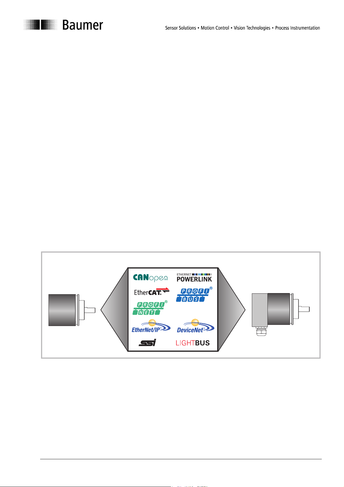
3 Product families
The structure of the product family is modular. Depending on what is required of the encoder, the basic
encoder and bus covers can be combined at will with the selected bus system.
The basic encoders differ in terms of accuracy, ambient conditions and the sampling system used.
Bus cover
The bus cover contains the entire electronic circuitry for measured value processing and the Ethernet
communication.
magtivo
has a resolution of 1024 steps per revolution with 10 bit, features a magnetic sampling system and is suitable
for operation in extreme ambient conditions.
multivo
has a resolution of 8192 steps per revolution with 13 bit, features an optical/magnetic sampling system and is
suitable for standard applications.
activo
features a 18 bit resolution of 262144 steps per turn, applies an optical/magnetic sensing method with
integrated analogue/digital conversion and is intended for ultra-precise sensing applications.
The basic encoder comprises a singleturn and a multiturn encoder. The multiturn encoder features a 16 bit
resolution respectively 65536 turns, or a 14 bit resolution corresponding to 16384 turns (multivoPlus). The
bus covers differ by their integrated bus interface.
Available bus interfaces: CANopen, DeviceNet, EtherCAT, Ethernet/IP, LIGHTBUS (fiber-optic), Profibus-DP,
Profinet, Power over EtherCAT (PoE), Powerlink, SAE J1939, SSI.
Except for encoders with fiber-optic interface, all encoders enable parameterization by bus interface.
Functional principle:
®
®
®
/multivoPlus
basic encoder
bus cover
complete encoder
SAE J1939
Manual_EtherCAT_PoE_BIDE_EN.doc 5/19 Baumer IVO GmbH & Co. KG
11.11.10 Villingen-Schwenningen, Germany
Page 6

4 Encoder operating parameters
Significance of operating parameters
Product
Product
GCAMW(S)
GCMMW(S)
GDAMW(S)
GDMMW(S)
GXAMW(S)
GXMMW(S)
GBAMW(S)
GBMMW(S)
family
Decimal Hex Bit Decimal Hex Bit Decimal Hex Bit
magtivo
magtivo
activo
activo
multivo
multivo
®
®
®
®
®
®
multivoPlus
multivoPlus
These are ROM default parameters upon delivery.
Firmware version (0x100A) V4.00 provides a scaling function for customer-specific parameterization
of resolution, total measuring range, direction of rotation and preset. Refer also to chapter SDO,
object 0x6000.
Resolution per
turn Number of turns Measuring range
4096 1000 12 1 1 0 4096 1000 12
4096 1000 12 65536 10000 16 268435456 10000000 28
262144 40000 18 1 1 0 262144 40000 18
262144 40000 18 16384 4000 14 4294967296 100000000 32
8192 2000 13 1 1 0 8192 2000 13
8192 2000 13 65536 10000 16 536870912 20000000 29
262144 40000 18 1 1 0 262144 40000 18
262144 40000 18 16384 4000 14 4294967296 100000000 32
Manual_EtherCAT_PoE_BIDE_EN.doc 6/19 Baumer IVO GmbH & Co. KG
11.11.10 Villingen-Schwenningen, Germany
Page 7

5 Encoder data
5.1 CoE (CANopen over EtherCAT)
Since there are many device and application profiles for a large variety of CANopen applications these may
also be applied at EtherCAT slaves.
The EtherCAT encoder is implementing a part of the DS406 encoder device profile.
Explanations and description of implemented Service Data Objects in chapter SDO.
5.2 PDO (Process Data Object)
With XML file BAUMER IVO GxxMW_H encoder.xml
The encoder will transmit following PDO (input data) as process data:
Value Data Type Significance
Position value
Warnings
System Time
Device identification in the TwinCAT system environment as „BAUMER IVO EtherCAT encoder“.
Linking the position value with the high resolution system time enables the master to calculate for example
speed respectively acceleration. Thus any jitter occurring in the communication system will not have any
impact.
With XML file BAUMER IVO FAST GxxMW_H encoder.xml
PDO (Process Data Object)
The encoder will transmit following PDO (input data) as process data:
Value Data type Significance
Position Value
Device identification in the TwinCAT system environment as „BAUMER IVO FAST EtherCAT encoder“.
Shorter clock cycles (up to 125 µs) are possible.
UDINT Actual absolute encoder position value. For value range please refer to
chapter „Encoder operating parameters“
UINT Warnings
2
= 1: Battery warning, Lithium cell voltage is not sufficient
Bit 2
UDINT Actual system time, resolution in ns
UDINT Actual absolute encoder position value. For value range please refer to
chapter „Encoder operating parameters“
Manual_EtherCAT_PoE_BIDE_EN.doc 7/19 Baumer IVO GmbH & Co. KG
11.11.10 Villingen-Schwenningen, Germany
Page 8

5.3 SDO (Service Data Object)
Under TwinCAT there is access to the SDO objects under CoE - Online.
Please consider that every CoE access (mailbox communication) will shortly interrupt generation of encoder
input data for the time of mailbox communication. With short cycle times in Distributed Clocks Mode this may
imply that not in every Sync cycle a new position is detected.
Manual_EtherCAT_PoE_BIDE_EN.doc 8/19 Baumer IVO GmbH & Co. KG
11.11.10 Villingen-Schwenningen, Germany
Page 9

Object list Detailed explanations on the most important SDO objects
Object 0x1000 Device Type
SubIndex 0
Data type Unsigned 32
Access ReadOnly
Default Multiturn: 0x00020196
Singleturn: 0x00010196h
EEPROM No
Significance Information on device profile and device type
Values
Object 0x1008 Device Name
SubIndex 0
Data type VISIBLE_STRING
Access ReadOnly
Default According to connected basic encoder
"GXMMW_H","GXAMW_H","GCMMW_H ","GCAMW_H ",
"GDMMW_H","GDAMW_H",“GBMMW_H ","GBAMW_H "
EEPROM No
Significance Device name in ASCII
Values
Object 0x1009 Hardware Version
SubIndex 0
Data type VISIBLE_STRING
Access ReadOnly
Default
EEPROM No
Significance Hardware version in ASCII
Values
Object 0x100A Manufacturer Software Version
SubIndex 0
Data type VISIBLE_STRING
Access ReadOnly
Default
EEPROM No
Significance Software version in ASCII
Values
Object 0x1010 SAVE Application Parameter
Object 0x1010 is utilized to save device-specific objects (0x6000..0x6FFF) out of RAM into non-volatile memory
(EEPROM). To prevent inadvertent saving operations the signature „save“ must be written into object 0x1010
Subindex 0.
Signature MSB LSB
ISO 8859 character
hex
e v a s
0x65 0x76 0x61 0x73
Manual_EtherCAT_PoE_BIDE_EN.doc 9/19 Baumer IVO GmbH & Co. KG
11.11.10 Villingen-Schwenningen, Germany
Page 10

Object 0x1011 RESTORE Application Parameter
Object 0x1011 restores ROM default in device-specific objects (0x6000..0x6FFF) both in RAM and EEPROM. To
prevent any inadvertent restore, the signature „load“ must be written in object 0x1011 Subindex 0.
Signature MSB LSB
ISO 8859 character
hex
Object 0x1018 Identity Object
SubIndex 0
Data type Unsigned 8
Access ReadOnly
Default 4
EEPROM No
Significance Maximum supported subindex
Values 4 = Maximum supported subIndex
SubIndex 1
Data type Unsigned 32
Access ReadOnly
Default Ech
EEPROM No
Significance VendorID for Baumer IVO GmbH & Co. assigned by CiA
Values 0xEC (in the Internet under www.can-cia.de)
SubIndex 2
Data type Unsigned 32
Access ReadOnly
Default 0x0A Æ GXMMW_H ; 0x0B Æ GXAMW_H
0x0C Æ GCMMW_H ; 0x0D Æ GCAMW_H
0x0E Æ GBMMW_H, GDMMW_H ; 0x0F Æ GBAMW_H, GDAMW_H
EEPROM No
Significance Product Code
Values
SubIndex 3
Data type Unsigned 32
Access ReadOnly
Default
EEPROM No
Significance Revision no.
Values
SubIndex 4
Data type Unsigned 32
Access ReadOnly
Default
EEPROM No
Significance Serial no.
Values
d a o l
0x64 0x61 0x6F 0x6C
Manual_EtherCAT_PoE_BIDE_EN.doc 10/19 Baumer IVO GmbH & Co. KG
11.11.10 Villingen-Schwenningen, Germany
Page 11

Object 0x1A00 TxPDO1 Mapping
SubIndex 0
Data type Unsigned 8
Access ReadOnly
Default
EEPROM No
Significance Maximum supported subindex
Values 3
SubIndex 1
Data type Unsigned 32
Access ReadOnly
Default
EEPROM No
Significance Position value
Values 0x6004
SubIndex 2
Data type Unsigned 16
Access ReadOnly
Default
EEPROM No
Significance Warnings
Values 0x6505
SubIndex 3
Data type Unsigned 32
Access ReadOnly
Default
EEPROM No
Significance System time
Values 0x2000
Device-specific objects
Object 0x6000 Operating parameters
SubIndex 0
Data type Unsigned 16
Access ReadWrite
Default 0 , scaling OFF, CW
EEPROM Yes
Significance Operating parameters
Values
Bit 0: direction of rotation
0 CW
1 CCW
Entries ≠ default values are only effective with enabled scaling function (0x6000).
Bit 2: scaling function ON/OFF (firmware version V4.00 and up)
0 scaling disabled. Encoder provides raw data (less offset).
1 scaling enabled. Encoder provides position values under consideration of scaling factor
and offset ².
Example: Value 0x0004 -> scaling on, CW
² Firmware version (0x100A) V4.00 and up provide here an optional scaling function, otherwise customerspecific parameterization as resolution, total measuring range, direction of rotation and preset are not
effective.
Above parameters are first saved volatile in the encoder RAM. If required, non-volatile saving in EEPROM is by
utilizing object SAVE Application parameter (0x1010).
Please note that with enabled scaling the input data (TxPDO) are generated considerably more slowly since the
encoder requires additional processing time for scaling calculations. In other words, the programmed PLC cycle times
for encoder readout have to be correspondingly prolonged.
Manual_EtherCAT_PoE_BIDE_EN.doc 11/19 Baumer IVO GmbH & Co. KG
11.11.10 Villingen-Schwenningen, Germany
Page 12

Guide values:
Device Input data
4/10 byte PDO
GXMMW_H 4 111µs 407µs 125µs 500µs
GXMMW_H 10 197µs 492µs 250µs 1000µs
Cycle time with
scaling OFF
Cycle time with
scaling ON
Cycle time in mode
Distributed Clocks with
scaling OFF
Cycle time in mode
Distributed Clocks with
scaling ON
Object 0x6001 Measuring units per revolution
SubIndex 0
Data type Unsigned 32
Access ReadWrite
Default 0x2000 = 8192 = 13bit Æ GXxMW_H
EEPROM Yes
Significance Optional number of steps per revolution.
Values 1..n.. max. number of steps per revolution (0x6501)
In general, when writing on this object any previously saved offset (0x6509) will be cleared (value = 0).
Object 0x6002 Total measuring range
SubIndex 0
Data type Unsigned 32
Access ReadWrite
Default 0x20000000 = 536870912 = 29bit Æ GXMMW_H
EEPROM Yes
Significance Total measuring range in steps optionally programmable.
Values 1..n.. max. total measuring range in steps (0x 6502)
0x1000 = 4096 = 12bit Æ GCxMW_H
0x40000 = 262144 = 18bit Æ GBxMW_H, GDxMW_H
Entries ≠ default values are only effective with enabled scaling function (0x6000).
0x2000 = 8192 = 13bit Æ GXAMW_H
0x10000000 = 268435456= 28bit Æ GCMMW_H
0x1000 = 4096 = 12bit Æ GCAMW_H
0x80000000 = 2147483648 = 31bit ² Æ GBMMW_H, GDMMW_H
0x40000 = 262144 = 18bit Æ GBAMW_H, GDAMW_H
Consequence : Number of revolutions = total measuring range / resolution
The maximum resolution (0x6502) must not be exceeded since otherwise the selected
total resolution range is too wide and will be rejected.
Entries ≠ default values are only effective with enabled scaling function (0x6000).
² with disabled scaling 32 bit
In general, when writing on this object any previously saved offset (0x6509) will be cleared (value = 0).
Important for multiturn encoder operation:
If the programmed number of revolutions is a value ≠ 2
n
(1, 2, 4,...65536), re-programming after having crossed the
encoder zero point in powerless state is required.
Object 0x6003 Preset value
SubIndex 0
DatenTyp Unsigned 32
Zugriff ReadWrite
Default 0
EEPROM Yes
Beschreibung Optionally programmable position value.
Werte 0..actual total measuring range (0x6002) -1
Manual_EtherCAT_PoE_BIDE_EN.doc 12/19 Baumer IVO GmbH & Co. KG
11.11.10 Villingen-Schwenningen, Germany
In this operation an offset value is calculated and saved in object 0x6509.
Entries ≠ default values are only effective with enabled scaling function (0x6000).
Page 13

Object 0x6004 Position value
SubIndex 0
Data type Unsigned 32
Access ReadOnly
Default
EEPROM No
Significance Value of actual position in steps
Values 0..actual total measuring range (0x6002) -1
Object 0x6501 Max. measuring units per revolution (max. resolution in steps)
SubIndex 0
Data type Unsigned 32
Access ReadOnly
Default 0x2000 = 8192 = 13bit Æ GXxMW_H
0x1000 = 4096 = 12bit Æ GCxMW_H
0x40000 = 262144 = 18bit Æ GBxMW_H, GDxMW_H
EEPROM No
Significance Maximum singleturn resolution in steps
Values
Object 0x6502 Number of distinguishable revolutions
SubIndex 0
Data type Unsigned 32
Access ReadOnly
Default 0x10000 = 65536= 16bit Æ GXMMW_H
0x10000 = 65536= 16bit Æ GCMMW_H
0x2000 = 8192 = 13bit ² Æ GBMMW_H, GDMMW_H
EEPROM No
Significance Maximum number of revolutions
Values With singleturn encoders =0, otherwise according to basic encoder
² with disabled scaling 14 bit
Object 0x6505 Warnings )
SubIndex 0
Data type Unsigned 16
Access ReadOnly
Default 0
EEPROM No
Significance Warnings
Values Multiturn encoder
Bit 2 :
0 Æ Lithium battery OK
1 Æ Lithium battery NOK
Object 0x6509 Offset
SubIndex 0
Data type Unsigned 32
Access ReadOnly
Default 0
EEPROM Yes
Significance Value is calculated upon writing on object Preset (0x 6003)
Values
5.4 Free Run Mode (default)
Encoder generates process data in a cyclic asynchronous manner.
Manual_EtherCAT_PoE_BIDE_EN.doc 13/19 Baumer IVO GmbH & Co. KG
11.11.10 Villingen-Schwenningen, Germany
Page 14

5.5 Distributed Clocks Mode
Distributed clocks mode enables exactly the same time with all bus users.
The encoder can be utilized and configurated as reference clock for synchronisation purposes of both other
users and master. Thus a high-precision time base is available throughout the network.
The encoder generates process data synchronously to a Sync Signal .
5.5.1 Activation Distributed Clocks under TwinCAT
Afterwards E/A devices reload
(F4) is mandatory
5.6 Network management
The encoder state machine can be switched over by online in the TwinCAT system manager (similar to
network management at CANopen)
Manual_EtherCAT_PoE_BIDE_EN.doc 14/19 Baumer IVO GmbH & Co. KG
11.11.10 Villingen-Schwenningen, Germany
Page 15

6 Terminal assignment and commissioning
6.1 Mechanical mounting
Shaft encoders
• Mount encoder housing by help of the mounting holes and three screws (square flange: 4 screws)
provided at flange. Observe thread diameter and depth.
• There is an alternative mounting option in any angular position by eccentric fixings, see under
accessories.
• Connect drive shaft and encoder shaft by using an appropriate coupling. The shaft ends must not touch
each other. The coupling must equalize any shifts due to temperature as well as mechanical tolerances.
Observe the maximum permitted axial or radial shaft load. For appropriate couplings please refer to
accessories.
• Tighten the mounting screws firmly.
End shaft encoders
• Mounting by clamping ring
Open clamping ring completely before mounting the encoder.
Slide encoder onto the drive shaft and tighten the clamping ring firmly.
• Adjusting element with rubber buffer
Slide encoder onto the drive shaft and insert cylindrical pin into adjusting element (with rubber buffer)
provided by customer.
• Spring washer
Spring washer assembly at the encoder housing is by inserting the screws into the mounting holes. Slide
encoder onto the drive shaft and assemble spring washer at the contact surface.
6.2 Electrical connection
Assignment – M12 connector
Follow also the instructions of the respective supplier.
- Press mating connector softly into the plug.
- Turn mating connector carefully until the code mark is interlocking the corresponding space provided by the
plug. Insert bushing completely. Tighten the nut as far as possible.
Exchange bus cover
The bus cover is to be stored and transported whilst in the ESD bag only. The bus cover has to fit the case
tightly and has to be firmly secured by screws.
Remove bus cover
- Unscrew both fixing screws of the bus cover.
- Loosen bus cover carefully and remove it in axial direction.
Plug on bus cover
- Plug the bus cover carefully onto the D-SUB plug of the basic encoder, then push it over the rubber seal.
Avoid the case getting wedged. The bus cover has to fit tightly the basic encoder.
- Tighten both fixing screws firmly and conformable.
- An optimized connection between encoder case and the braiding shield of the supply cable is only achieved
by a complete and close fit of the bus cover onto the basic encoder (interlock).
Manual_EtherCAT_PoE_BIDE_EN.doc 15/19 Baumer IVO GmbH & Co. KG
11.11.10 Villingen-Schwenningen, Germany
Page 16

6.2.1 Initialising under TwinCAT system manager
• The included XML file must be copied into the respective directory:
..\TwinCAT\Io\EtherCAT
• Start TwinCAT system manager
• Then proceed as described below.
1
2
3
5
Now EtherCAT devices should respond as shown above!
4
Manual_EtherCAT_PoE_BIDE_EN.doc 16/19 Baumer IVO GmbH & Co. KG
11.11.10 Villingen-Schwenningen, Germany
Page 17

6.2.2 Terminal assignment
Bus cover EtherCAT
60
L/A
OUT
IN
Status-Anzeige
Status display
DUO-LED
63
Link/Activity
Anzeige/display
LED
OUT IN
3
4
3
1 x M12 connector (male), a-coded
1
2
4
2 x M12 connector (female), D-coded
2
1
Pin Assignment
Pin Assignment
1 UB (10...30 VDC) 1 TxD+
2 N.C. 2 RxD+
3 GND 3 TxD-
4 N.C. 4 RxD-
Bus cover Power over EtherCAT (PoE)
L/A
3
4
1 x M12 connector (female), D-coded
2
1
Pin Assignment
1 TxD+
2 RxD+
3 TxD-
4 RxD-
Manual_EtherCAT_PoE_BIDE_EN.doc 17/19 Baumer IVO GmbH & Co. KG
11.11.10 Villingen-Schwenningen, Germany
Page 18

6.3 Display elements
6.3.1 State indicator
The bus cover provides a DUO LED (green/red) operating in line with EtherCAT Indicator Specification
V0.91.
DUO-LED green RUN State
RUN State Status Description Category
Off INIT The device is in state INIT Mandatory
Blinking PRE-OPERATIONAL The device is in state PRE-OPERATIONAL Mandatory
Single Flash SAFE-OPERATIONAL The device is in state SAFE-OPERATIONAL Mandatory
On OPERATIONAL The device is in state OPERATIONAL Mandatory
Flickering
Double Flash Reserved Reserved for future use reserved
Triple Flash Reserved Reserved for future use reserved
Quadruple Reserved Reserved for future use reserved
INITIALISATION or
BOOTSTRAP
DUO-LED red ERR State
ERR State Error Description Example Category
Off No error
Flickering Booting Error Booting
Blinking Invalid Configuration General Configuration Error
Single Flash
Double Flash
Triple Flash Reserved Reserved for future use Reserved
Quadruple Flash Reserved Reserved for future use Reserved
On
Unsolicited State
Change
Application Watchdog
Timeout
PDI Watchdog
Timeout
6.3.2 Link/Activity indicator
One LED each for input and output.
Link Activity State of Link/Activity indicator
Yes No On
Yes Yes Flickering
No Not applicable Off
Note: All LED´s are “off“ if the encoder is under power supply but not yet connected to Ethernet.
The device is booting and has not yet entered the INIT
state, or:The device is in state BOOTSTRAP.Firmware
download operation in progress
The EtherCAT
communication of the
device is in working
condition
Error was detected. INIT
state reached, but
Parameter "Change" in the
AL status register is set to
0x01:change error
Slave device application
has changed the EtherCAT
state autonomously:
Parameter "Change" in the
AL status register is set to
0x01:change/error.
An application watchdog
timeout has occurred.
A PDI Watchdog timeout
has occurred
Mandatory
Checksum Error in Flash
Memory.
State change commanded
by master is impossible due
to register or object settings.
Synchronisation Error,
device enters SafeOperational automatically.
Sync Manager Watchdog
timeout
Application controller is not
responding any more
Optional
Optional
Mandatory
Mandatory
Mandatory
Optional
Manual_EtherCAT_PoE_BIDE_EN.doc 18/19 Baumer IVO GmbH & Co. KG
11.11.10 Villingen-Schwenningen, Germany
Page 19

6.4 Bus cover Power over EtherCAT (PoE)
Based on the IEEE-standard 802.3af, the Baumer EtherCAT encoder with PoE bus cover is interacting as PD
(Powered Device) with a corresponding PSE (Power Sourcing Equipment) module. Signal and power
transmission is by 4-wire standard EtherCAT/Ethernet cable (for example CAT-5). The PSE will identify the
encoder as PD after poweron by the procedure specified in IEEE standard 802.3af.
Encoder supply of 48 V must be provided by an auxiliary PSE module (for example Beckhoff EtherCAT
branch EK1132).
PoE encoder at EK1132 EtherCAT-branch
Run
Power OK
Features
- Functionality compliant to standard IEEE Std 802.3af
- Excess temperature protection
- PoE mains unit galvanically insulated
- Hot-Connect feasible (connecting/disconnecting the device during operation)
Technical data
Poe Leistungsklasse: 1 (max. 4 W)
PoE supply voltage: 44..57 VDC
Current consumption: ≤50mA (bei 48 VDC)
Cable length: max.100 m
Manual_EtherCAT_PoE_BIDE_EN.doc 19/19 Baumer IVO GmbH & Co. KG
11.11.10 Villingen-Schwenningen, Germany
 Loading...