

Page 1

Manual
Encoder Programming Software ProGeber 1.4
Baumer IVO GmbH & Co. KG
Dauchinger Strasse 58-62
DE-78056 Villingen-Schwenningen
Phone +49 (0)7720 942-0
Fax +49 (0)7720 942-900 05.11 · 174.02.032/4
info.de@baumerivo.com Subject to modification in technic and design.
www.baumer.com Errors and omissions excepted.
Page 2

Content
Introduction 4
1
1.1 Product assignment 4
2 General information 5
2.1 System requirements 5
2.2 Installation 5
2.3 Software state 5
2.4 Notes for operation 6
3 The program ProGeber 7
3.1 Basic information 7
3.2 Program run 7
3.2.1 Select encoder 8
3.2.2 Encoder connected to PC "Automatic choose" 9
3.2.3 Select type of encoder from table "Manual choose" 10
3.2.4 Start programming of encoder 11
4 Program encoder 13
4.1 Menu bar 13
4.1.1 File 13
4.1.2 Settings 14
4.1.3 Extras 15
4.1.4 Info 16
4.1.5 Reprogramming 16
4.1.6 Load programming 16
4.1.7 Save programming 16
4.1.8 Print 16
4.1.9 Load encoder data 16
4.1.10 Save data in encoder 16
4.1.11 Display the position 16
4.2 Explanation of programming mask „resolution“ 17
4.2.1 Code (steps) 18
4.2.2 Code (Revolutions) 18
4.2.3 Code format 18
4.2.4 Counting direction 19
4.2.5 Preset (offset) 19
4.2.6 Revolutions 19
4.2.7 Steps / revolution 19
4.2.8 Entire resolution 20
4.2.9 Back to main menu 20
4.2.10 Dialog window 20
4.2.11 Display type of encoder 20
4.2.12 Read encoder data 21
4.2.13 Send encoder data 21
4.3 Explanation of programming mask „outputs“ for parallel encoders 22
4.3.1 Special outputs 23
4.3.2 Least significant bit (LSB) revolutions 23
4.3.3 Domain „special outputs“ 23
Manual_ProGeber_V1-40_EN.doc 2/40 Baumer IVO GmbH & Co. KG
10.05.11 Villingen-Schwenningen, Germany
Page 3

4.3.4 Output logic 24
4.3.5 Steps 24
4.3.6 Revolution 24
4.3.7 Entire resolution 24
4.4 Explanation of programming mask „outputs“ for SSI encoders 25
4.4.1 Output format 26
4.4.2 Special bits SSI 27
4.4.3 Number of data bits 27
4.4.4 Assigned outputs 27
4.4.5 Domain special outputs 27
4.4.6 Output logic 28
4.4.7 Monoflop time 28
4.5 Explanation of mask „Position display“ 29
4.6 Explanation „Set position“ 30
4.7 Explanation „Teach In“ 31
4.8 Explanation cam switching mechanism 34
5 Wiring the encoders 35
5.1 Wiring between PC and encoder 35
5.1.1 Contact parallel encoder 35
5.1.2 Contact SSI encoder 37
5.1.3 Contact SSI bus cover 38
6 Appendix 39
6.1 Description of parallel encoder 39
6.2 Description of SSI encoder 40
Manual_ProGeber_V1-40_EN.doc 3/40 Baumer IVO GmbH & Co. KG
10.05.11 Villingen-Schwenningen, Germany
Page 4

1 Introduction
1.1 Product assignment
Shaft encoder
Product Product family Interface
GBAMW multivoPlus - Singleturn SSI bus cover RS232
GBLMW multivoPlus - Multiturn SSI bus cover RS232
GBMMW multivoPlus - Multiturn SSI bus cover RS232
GCAMW
GCMMW
GXAMW
GXMMW
GXP1W Parallel RS232
GXP2W SSI RS232
GXN1W Cam encoder RS232
End shaft encoder
Product Product family Interface
GBAMS multivoPlus - Singleturn SSI bus cover RS232
GBLMS multivoPlus - Multiturn SSI bus cover RS232
GBMMS multivoPlus - Multiturn SSI bus cover RS232
GCAMS
GCMMS
GXAMS
GXLMS
GXMMS
Hollow shaft encoder
Product Product family Interface
magtivo® - Singleturn SSI bus cover
magtivo® - Multiturn SSI bus cover
multivo® - Singleturn SSI bus cover
multivo® - Multiturn SSI bus cover
magtivo® - Singleturn SSI bus cover
magtivo® - Multiturn SSI bus cover
multivo® - Singleturn SSI bus cover
multivo® - Multiturn SSI bus cover
multivo® - Multiturn SSI bus cover
RS232
RS232
RS232
RS232
RS232
RS232
RS232
RS232
RS232
G1AMH
G2AMH
G1MMH
G2MMH
GXP1H Parallel RS232
G1P2H SSI RS232 or RS485
GXP2H SSI RS232 or RS485
GXN1H Cam encoder RS232
Manual_ProGeber_V1-40_EN.doc 4/40 Baumer IVO GmbH & Co. KG
10.05.11 Villingen-Schwenningen, Germany
multivo® - Singleturn SSI bus cover
multivo® - Singleturn SSI bus cover
multivo® - Multiturn SSI bus cover
multivo® - Multiturn SSI bus cover
RS232
RS232
RS232
RS232
Page 5

2 General information
2.1 System requirements
A PC with operating system Windows Windows 95/98/2000/XP or NT.
2.2 Installation
The installation of ProGeber depends on the programming interface of the encoder. Both
variations of RS232 and RS485 are filed on the CD-ROM under separate directories.
Encoder with RS232 interface (Windows 95/98/2000/XP/NT):
For operation systems Windows 95/98/2000/XP/NT, encoder choice menu, please refer to
chapter “Introduction”:
How to start ProGeber Software „setup_ProGeber.exe“ out of directory „RS232 interface“.
Encoder with RS485 interface (Windows 95/98/NT):
For operation systems 95/98/NT, encoder choice menu, please refer to chapter “Introduction”:
Installation of serial driver out of directory „RS485 interface“ by starting file
„setup_Ser_Driver.exe“, followed by starting the ProGeber Software file
„setup_ProGeber_KiS.exe“. Finally the computer must boot up anew for integration of the
serial driver into the operation system.
Encoder with RS485 interface (Windows 2000):
For operation system Windows 2000, encoder choice menu please refer to chapter
“Introduction”:
Installation of the serial driver out of the directory „RS485 Interface Win2k“ by starting file
„setup_Ser_Driver_Win2k.exe“, followed by starting the ProGeber Software file
„setup_ProGeber_KiS.exe“. Finally the computer must boot up anew for integration of the
serial driver into the operation system.
The installation is menu-driven.
Note: Under Windows NT/XP and Windows 2000 the installation can only be executed with
administrator rights.
2.3 Software state
ProGeber version 1.4 is replacing former ProGeber versions.
Manual_ProGeber_V1-40_EN.doc 5/40 Baumer IVO GmbH & Co. KG
10.05.11 Villingen-Schwenningen, Germany
Page 6

2.4 Notes for operation
• Any wiring on encoder plug or control desk is to be effected in powerless state
only. The encoder plug must not be plugged in or out whilst under voltage.
• Please check and plug all plug-in connections before switching on.
• Caution!
Incorrect encoder programmation may lead to breakdown of the system.
Product information
The information in this publication is subject to change without prior notice.
Baumer IVO GmbH & Co. KG does not give any warranty of specified quality or functionality
with respect to the information contained in this publication. Baumer IVO GmbH & Co. KG
assumes no responsibility or liability for any errors or inaccuracies that may appear in this
manual.
Manual_ProGeber_V1-40_EN.doc 6/40 Baumer IVO GmbH & Co. KG
10.05.11 Villingen-Schwenningen, Germany
Page 7
3 The program ProGeber
3.1 Basic information
The program ProGeber is a software for programming Baumer IVO encoders. It enables the
reading out, the modification and the display of encoder data. Hereby the encoder parameters
can be read out, altered, programmed and displayed. To make the programming as easy as
possible, the user can select valid fields only. Fields that cannot be selected are highlighted in
grey. Before the encoder can be programmed, the type of encoder must be selected. Thus a
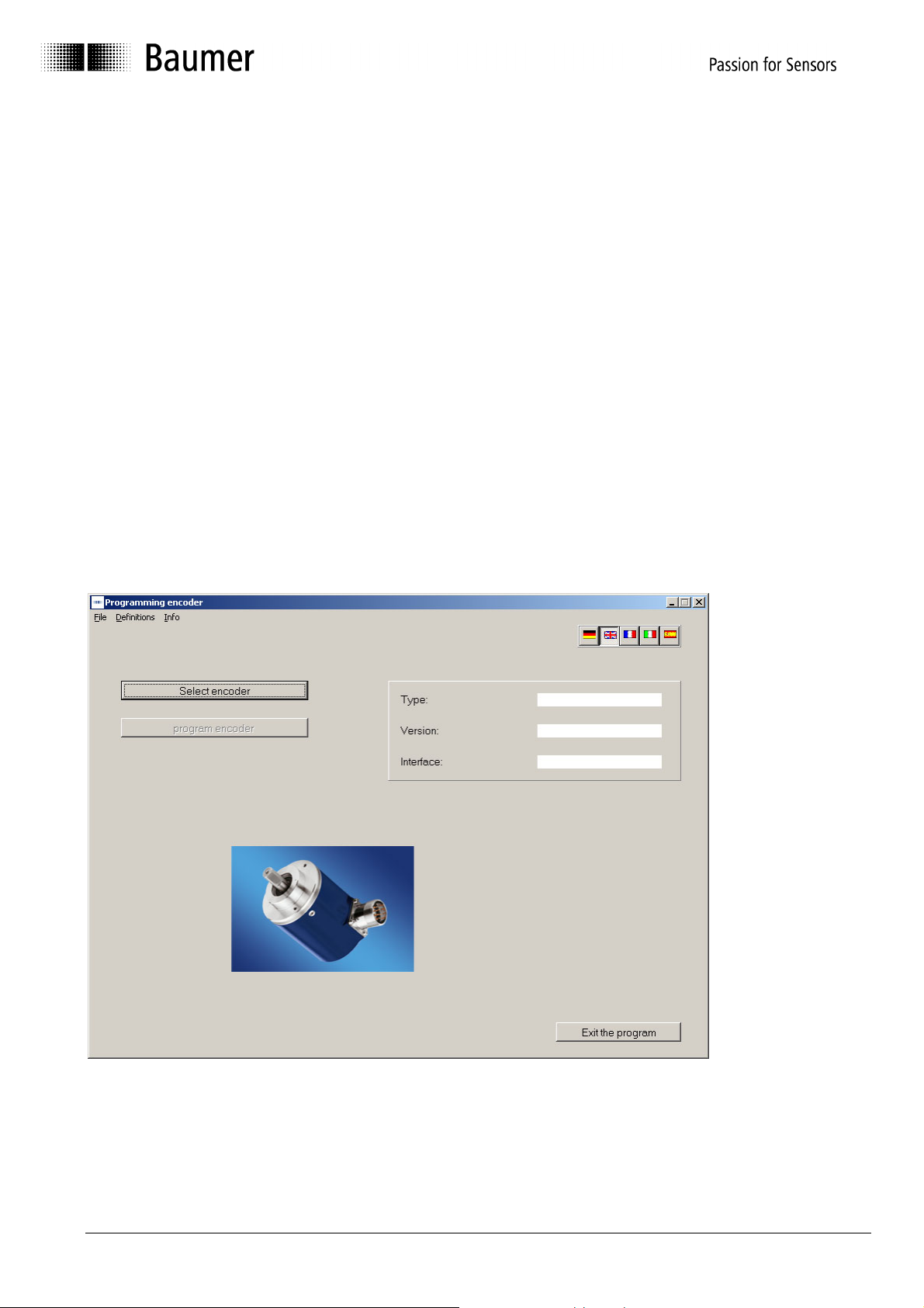
logical program run is achieved after starting the program:
1. Step Select language via the respective country's flag
2. Step Select type of encoder by clicking the button "Select encoder"
3. Step Programming can be started
If your encoder cannot be detected automatically and is not included in the selection menu as
well, please contact Baumer IVO GmbH & Co. KG.
3.2 Program run
After the opening image the following mask will appear:
The programming can only be started after selecting a type of encoder. The selection of the
encoders is described in the chapters „Encoder connected to PC ⇒ Automatic selection" and
„Select type of encoder from table ⇒ Manual selection".
Manual_ProGeber_V1-40_EN.doc 7/40 Baumer IVO GmbH & Co. KG
10.05.11 Villingen-Schwenningen, Germany
Page 8
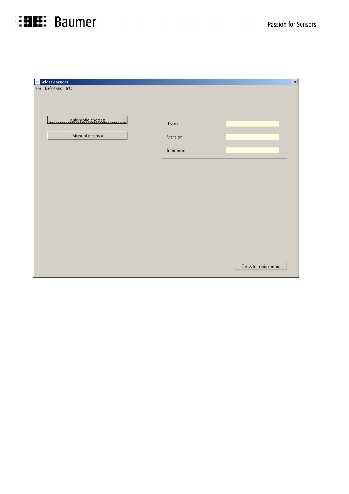
3.2.1 Select encoder
First step is selection of the encoder.
By the software an optional automatic selection is offered, provided the encoder is connected
to the interface. In case of lacking encoder connection, the desired encoder model can be
selected from the list.
Manual_ProGeber_V1-40_EN.doc 8/40 Baumer IVO GmbH & Co. KG
10.05.11 Villingen-Schwenningen, Germany
Page 9
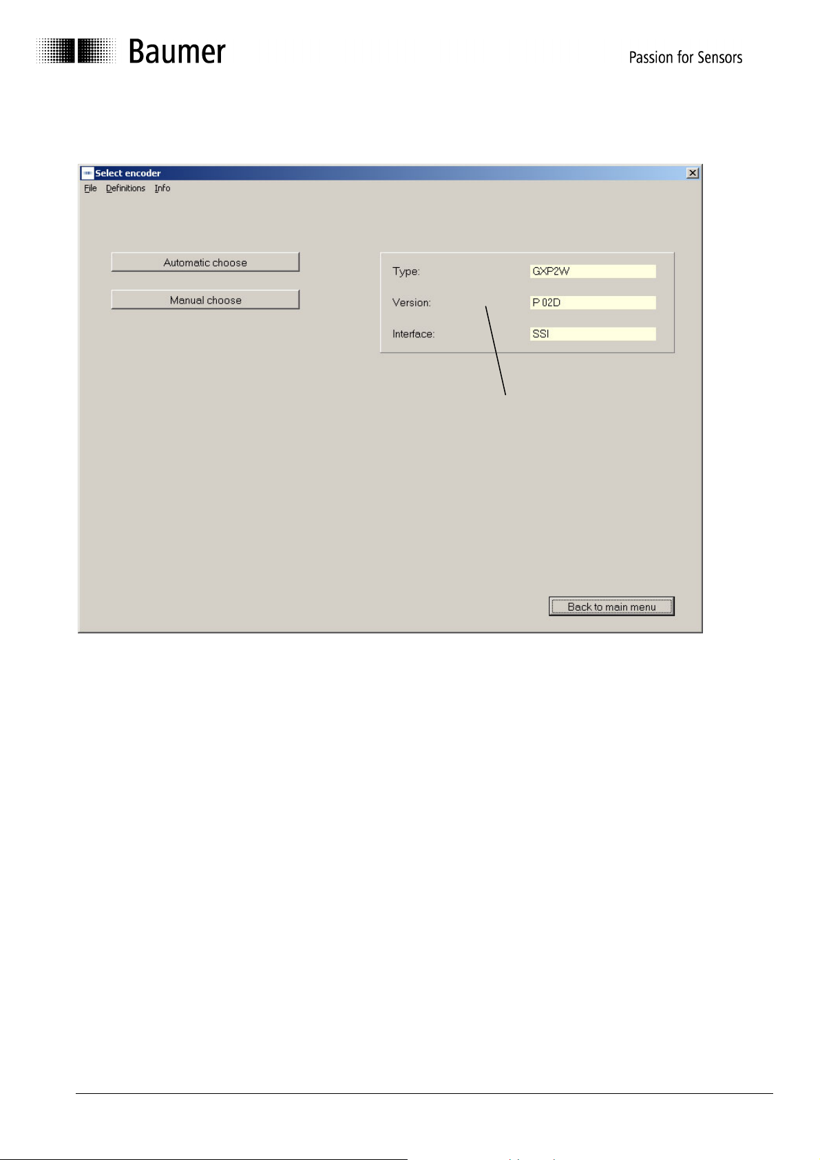
3.2.2 Encoder connected to PC "Automatic choose"
Automatically
detected type of
encoder
The type of encoder can be read out when the encoder is connected (automatic). This data is
necessary to provide the relevant parameters for programming. If no encoder is connected or if
the cable connection is not connected properly, an error message will be displayed. If the
automatically detected encoder does not correspond with the encoder's type label, please
contact Baumer IVO GmbH & Co. KG.
Manual_ProGeber_V1-40_EN.doc 9/40 Baumer IVO GmbH & Co. KG
10.05.11 Villingen-Schwenningen, Germany
Page 10
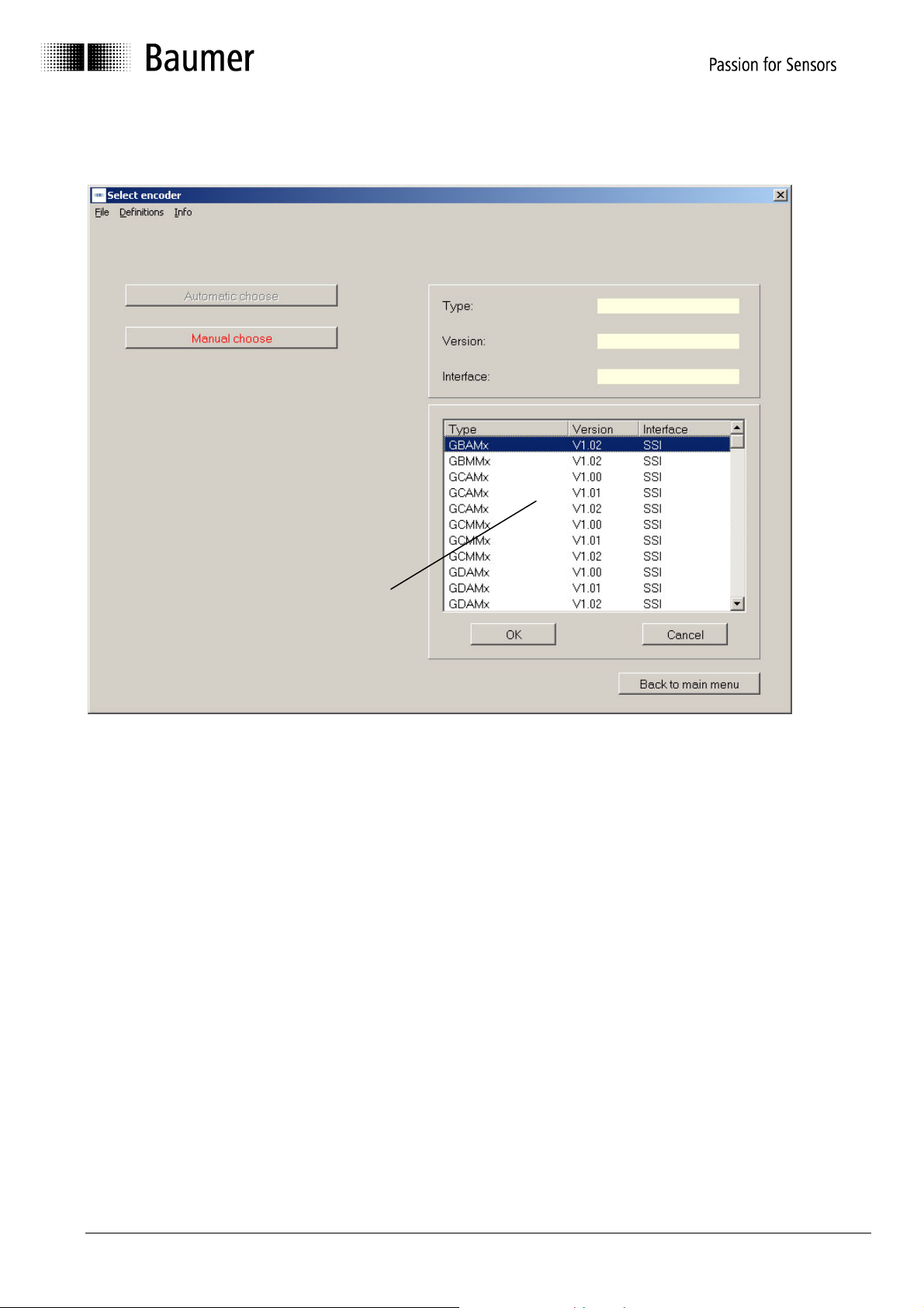
3.2.3 Select type of encoder from table "Manual choose"
Table for selecting
the type of
encoder
If no encoder is connected to the PC, the type of encoder can be selected from a table
(manual selection). The table contains the common types. It is not only the type that is
important but also the version. If your type should not be included, please contact
Baumer IVO GmbH & Co. KG. Type and version can be found on the type label of the
encoder.
Manual_ProGeber_V1-40_EN.doc 10/40 Baumer IVO GmbH & Co. KG
10.05.11 Villingen-Schwenningen, Germany
Page 11
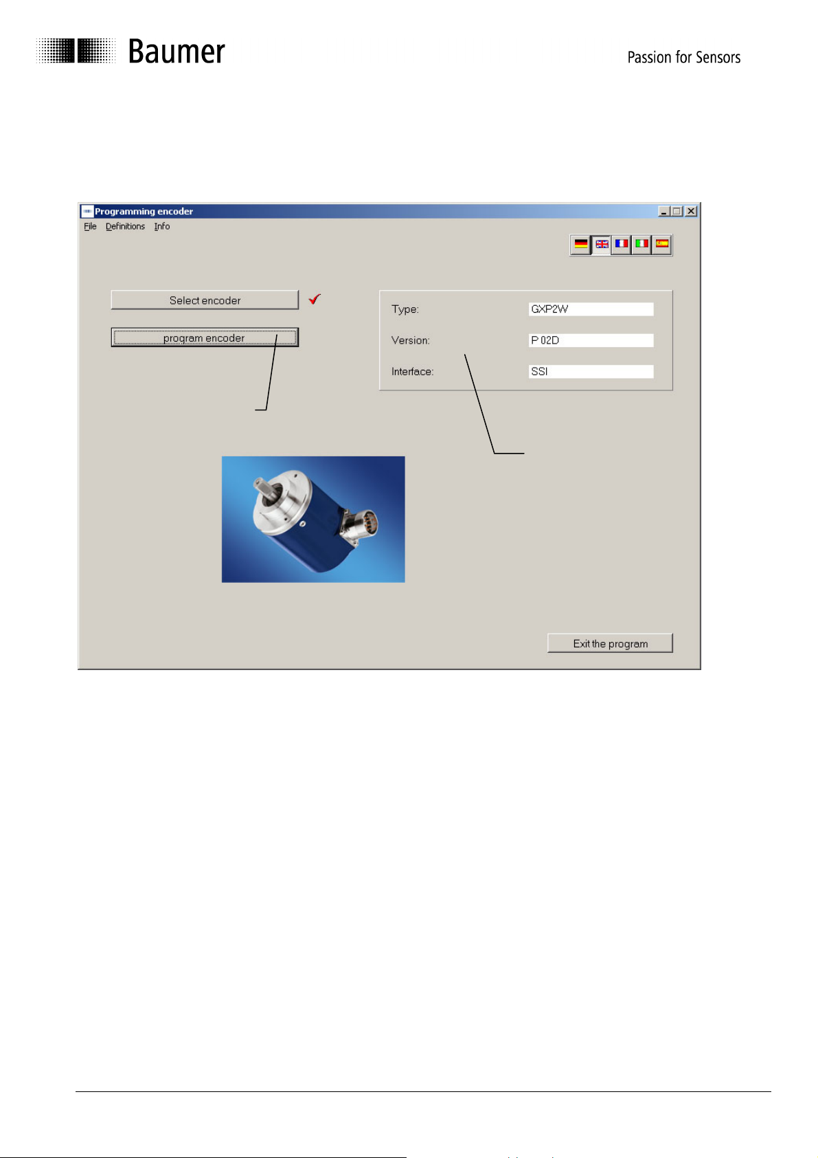
3.2.4 Start programming of encoder
After successfully selecting the encoder, you can start programming. The button "program
encoder" is now active. The selected encoder is once again displayed in the right mask.
Encoder program-
ming is active
Selected
encoder
Manual_ProGeber_V1-40_EN.doc 11/40 Baumer IVO GmbH & Co. KG
10.05.11 Villingen-Schwenningen, Germany
Page 12
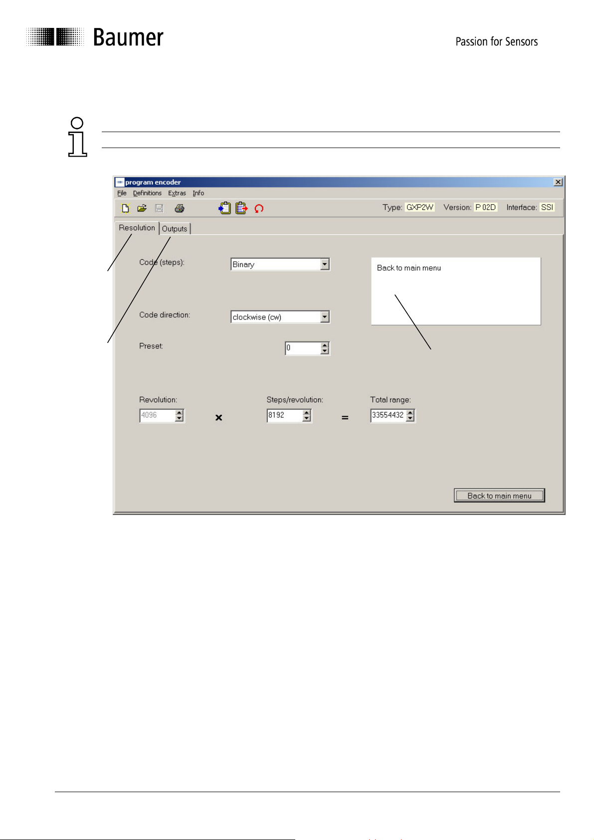
The programming mask now enables the programming of all parameters that are possible for
the respective encoder.
The mask may vary according to the corresponding encoder model
Register
card for the
resolution
Register
card for the
outputs
Dialog window
The parameters for the encoder can be set by means of the register cards for the resolution
and the outputs. The dialog window gives additional support, or that is to say explains the
window that has just been selected.
See chapter 4.2 for register cards „Resolution“.
The explanation for the register cards „Outputs for Parallel Encoders“ see chapter 4.3 and
„Outputs for SSI Encoders“ see chapter 4.4.
Manual_ProGeber_V1-40_EN.doc 12/40 Baumer IVO GmbH & Co. KG
10.05.11 Villingen-Schwenningen, Germany
Page 13

4 Program encoder
4.1 Menu bar
1
2
5 6 7 8 9 10
N° Chapter Button N° Chapter Button
1 4.1.1 File 7 4.1.7 Save programming
2 4.1.2 Settings 8 4.1.8 Print
3 4.1.3 Extras 9 4.1.9 Load encoder data
4 4.1.4 Info 10 4.1.10 Save data in encoder
5 4.1.5 Reprogramming 11 4.1.11 Display the position
6 4.1.6 Load programming
3 4
11
4.1.1 File
The following menu items can be selected in the "File" menu:
New: A programming mask with basic setting is loaded.
Open: A saved program can be loaded.
Save: The current data can be saved.
Save as: The current data can be saved with a name of your choice in a
directory of your choice.
Print: The current data can be printed for archiving.
Select printer: A printer can be chosen.
Back to main menu: The programming mask is closed.
Manual_ProGeber_V1-40_EN.doc 13/40 Baumer IVO GmbH & Co. KG
10.05.11 Villingen-Schwenningen, Germany
Page 14

4.1.2 Settings
Click "settings" menu to select the serial interface COM 1 up to COM 6 to which the encoder is
connected. Furthermore, you can adjust the baud rate and the address of the encoder.
The other parameters such as parity, stop bits and data bits can be controlled here.
Manual_ProGeber_V1-40_EN.doc 14/40 Baumer IVO GmbH & Co. KG
10.05.11 Villingen-Schwenningen, Germany
Page 15

4.1.3 Extras
Call up data: The data is called up from the connected encoder
Send data: The current programming is saved in the encoder
Display position: The display mask is opened
(see chapter 4.5 „position display“)
Set position: The mask for assignment of any value desired is being opened.
(see chapter 4.6 Explanation „Set position“)
Teach in: The mask for the automatic scaling is displayed
(see chapter 4.7 „Explanation Teach in“)
Reset: The encoder is programmed to basic setting
Caution: Old encoder data will be overwritten!
Address encoder: The address set at the connected encoder is called up or set.
The mask may vary according to the corresponding encoder model
Manual_ProGeber_V1-40_EN.doc 15/40 Baumer IVO GmbH & Co. KG
10.05.11 Villingen-Schwenningen, Germany
Page 16

4.1.4 Info
Click "Info" menu to display the current software version of the ProGeber software and of the
encoder software.
4.1.5 Reprogramming
The display mask is reset to the basic setting.
The same function can also be released by „File ⇒ New“.
4.1.6 Load programming
A programming saved in the PC can be loaded.
The same function can also be released by „File ⇒ Open“.
4.1.7 Save programming
The current data is saved in the PC.
The same function can also be released by „File ⇒ Save“.
4.1.8 Print
The current encoder data is printed. The printout can be used for archiving.
The same function can also be released by „File ⇒ Print".
4.1.9 Load encoder data
The data from the connected encoder is called up.
The same function can also be released by „Extras ⇒ Call up data".
4.1.10 Save data in encoder
The current programming is saved in the encoder.
The same function can also be released by „Extras ⇒ Send data".
4.1.11 Display the position
The current position and the state of the special outputs are displayed.
The same function can also be released by „Extras ⇒ Display position“.
Manual_ProGeber_V1-40_EN.doc 16/40 Baumer IVO GmbH & Co. KG
10.05.11 Villingen-Schwenningen, Germany
Page 17

4.2 Explanation of programming mask „resolution“
The programming mask, with which the resolution of the encoder can be set, is explained in
detail below. The mask below shows the maximum possible settings. It may look different
according to the encoder model. Only parameters that are supported by the selected encoder
are being offered.
The mask may vary according to the corresponding encoder model.
14
12
13 11
1
2
3
4
10
5
8 7 6
9
N° Chapter Field N° Chapter Field
1 4.2.1 Code (steps) 8 4.2.8 Entire resolution
2 4.2.2 Code (revolution) 9 4.2.9 Back to main menu
3 4.2.3 Code format 10 4.2.10 Dialog window
4 4.2.4 Counting direction 11 4.2.11 Display type of encoder
5 4.2.5 Offset or preset 12 4.2.12 Read encoder data
6 4.2.6 Revolutions 13 4.2.13 Send encoder data
7 4.2.7 Steps / revolution 14 4.5 Position display
Manual_ProGeber_V1-40_EN.doc 17/40 Baumer IVO GmbH & Co. KG
10.05.11 Villingen-Schwenningen, Germany
Page 18

4.2.1 Code (steps)
Click Code (steps) to set the type of code for the singleturn range (steps / revolution). Possible
settings are e.g. Binary, Clamped Gray, Gray or BCD Code.
4.2.2 Code (Revolutions)
Click Code (revolutions) to set the type of code for the multiturn range (revolutions). Possible
settings are e.g. Binary, Gray or BCD Code.
4.2.3 Code format
Click Code format to determine the output format. In case of a closed code, the initial value is
displayed as a consecutive value. In case of a separated code, the initial value is separated
according to steps / revolution and revolutions.
Example:
In case of a setting of 10 steps / revolution and 16 revolutions
Separated code: Steps 0, 1, 2, 3....8, 9 → 0, 1, 2.....
Revolutions 0....................0 → 1, 1........
Steps Revolution
0....9 0
0....9 1
0....9 2
0....9 3
... ...
Closed code: Entire resolution: 0, 1, 2, 3...8, 9,......150, 151,...158, 159
Ð Ð
revolution 1 revolution 16
Manual_ProGeber_V1-40_EN.doc 18/40 Baumer IVO GmbH & Co. KG
10.05.11 Villingen-Schwenningen, Germany
Page 19

4.2.4 Counting direction
The counting direction offers two choices: "increasing clockwise" and "decreasing clockwise".
"Increasing clockwise" means that the position values increase in case of a clockwise rotation
(view from front of the encoder shaft), and decrease accordingly in case of "decreasing
clockwise".
Caution: The counting direction can be inverted via the hardware input V/R!
As far as the hardware is concerned, the counting direction must always be set first
and afterwards the preset value (offset).
4.2.5 Preset (offset)
The encoder can be set to any start count required. Depending on the encoder model the
start count can be defined as target (preset) or as difference between running value and target
(offset).
Once programming is finalized, encoders set to „offset“ therefore are only adding the offset
value to the current position value at first.
Even after completed programming the offset value can be assigned as well as preset value
via the encoder’s reset input by triggering a „high“ impulse for at least 100 ms.
4.2.6 Revolutions
Maximal number of turns to be counted by the encoder. The possible domain is
between 1 and 65536 revolutions. According to the type of encoder, the domain is
either optional or has to correspond to a power of two 20, 21, 22, ... 216 (1, 2, 4, ...
65536, depends on the encoder).
4.2.7 Steps / revolution
Number of steps defining one turn of the encoder shaft. Depending on the encoder’s interface,
the possible range lies between 2 and 8192 steps/turn. Any value within this range can be
selected. The maximum number of steps for encoders with parallel interface is 4096, with
standard SSI interface 8192 (high resolution activo encoders 262144 at singleturn range).
Manual_ProGeber_V1-40_EN.doc 19/40 Baumer IVO GmbH & Co. KG
10.05.11 Villingen-Schwenningen, Germany
Page 20

4.2.8 Entire resolution
The entire resolution is the sum of steps / revolution multiplied by the number of revolutions.
Thus, the domain depends on the setting of steps / revolution.
Formula of calculation for the entire resolution:
Revolutions X steps / revolution = entire revolution
Example: in case of 100 steps / revolution and a desired number of revolutions of 10,
the entire resolution is 1000.
According to the type of encoder, either the number of revolutions or the entire resolution can
be set. The other value is marked in grey and thus cannot be altered in any way. However, it is
being calculated and displayed.
Info: This resolution may also be applied for movements where the zero point is being crossed
several times in the same direction (continous operation).
4.2.9 Back to main menu
Click the button "Back to main menu" to leave the programming mask. If some parameters
have been modified, they can still be saved.
4.2.10 Dialog window
The dialog window contains info texts on the parameter that has just been selected. The info
texts describe the respective parameter with short explanations.
4.2.11 Display type of encoder
The encoder chosen manually or automatically after the program start is permanently
displayed in the programming mask. Thus, it can be checked whether the selected and the
existing encoder are identical.
Manual_ProGeber_V1-40_EN.doc 20/40 Baumer IVO GmbH & Co. KG
10.05.11 Villingen-Schwenningen, Germany
Page 21

4.2.12 Read encoder data
The connected encoder is read out. Before the register card for „resolution“ and „outputs“ is
overwritten, it can be saved. If the connected type of encoder is not identical with the selected
one, the following error message will be displayed:
If the selected type of encoder and the connected one are identical, the data will be read in
and displayed.
4.2.13 Send encoder data
The encoder connected to the interface is programmed with the set parameters. If the
connected type of encoder and the selected one are not identical, the following error message
will be displayed:
During the data transmission, the data is stored in the encoder while being protected against
power failure. The transmission takes a few seconds and is displayed as follows:
Manual_ProGeber_V1-40_EN.doc 21/40 Baumer IVO GmbH & Co. KG
10.05.11 Villingen-Schwenningen, Germany
Page 22

4.3 Explanation of programming mask „outputs“ for parallel encoders
The programming mask „outputs for parallel encoders“ is adapted to the connected encoder.
Fields highlighted in grey cannot be changed for the selected type in question. The following
mask shows a typical encoder with parallel output. The individual parameters are explained in
detail below.
1
N° Chapter Field
1 4.3.1 Special outputs
2 4.3.2 Least significant bit revolutions
3 4.3.3 Domain special outputs
4 4.3.4 Output logic
5 4.3.5 Steps
6 4.3.6 Revolutions
6
5
4
3
2
Manual_ProGeber_V1-40_EN.doc 22/40 Baumer IVO GmbH & Co. KG
10.05.11 Villingen-Schwenningen, Germany
Page 23

4.3.1 Special outputs
The special outputs available are marked in red. Their number is depending on the total
resolution selected as well as the code format. The outputs D19 to D23 allow a maximum
assignment of 5 special outputs.
The outputs may be assigned in optional way to one of the following 6 functions, whilst the
corresponding function selected can be assigned exclusively to one output.
• Preset 1: Output switches when the set value is exceeded.
• Preset 2: Output switches when the set value is exceeded.
• Speed monitoring: Output switches when the actual value falls below the set value. The
value input in turns/minute.
• Battery control: Output triggers as soon as the voltage value for the lithium cell is falling
below the critical point. However, the encoder function still remains secure for another three
months.
• DataValid: Output switches when the checking of the code is faulty.
• DataValid + battery control: Both functions are assigned to the same output as a collective
message
Open-circuited and closed-circuited can be changed via the function "output logic"
(see chapter 4.4.6 Output logic).
4.3.2 Least significant bit (LSB) revolutions
The input field „least significant bit turns“ only appears if the resolution of steps/turn is inferior
to the maximum resolution of 12 Bit thus indicating existing outputs not assigned. If so, the
position of the turns within the range of D8 to D12 can be shifted to the position of output D8.
4.3.3 Domain „special outputs“
The domain „special outputs“ is used to select the desired position or rpm at which the special
outputs are to switch. The domain can be displayed by moving the mouse to the input field.
Manual_ProGeber_V1-40_EN.doc 23/40 Baumer IVO GmbH & Co. KG
10.05.11 Villingen-Schwenningen, Germany
Page 24

4.3.4 Output logic
The function „output logic“ offers the choice between normal and inverted. In case of the
normal output logic, a logical zero is in fact displayed as zero. If, in contrast, the output logic is
inverted, a logical zero is displayed as 1.
Caution: The function "output logic", normal or inverted, refers to all 24 outputs.
Thus, the outputs for the position values are set as well.
4.3.5 Steps
The display for the steps (singleturn) shows the required outputs highlighted in blue. This
display can be used to determine the corresponding outputs for the wiring.
Caution: The steps are only shown in case of a closed code, otherwise the entire
resolution is displayed (see chapter 4.3.7 Entire resolution)
4.3.6 Revolution
The display for the revolution (multiturn) shows the required outputs highlighted in green. This
display can be used to determine the corresponding outputs for the wiring.
Caution: The steps are only shown in case of a separated code, otherwise the entire
resolution is displayed (see chapter 4.3.7 Entire resolution)
4.3.7 Entire resolution
If a closed code is set in the resolution, the entire resolution appears instead of "steps"
(singleturn) or "revolutions" (multiturn). The entire resolution is displayed in blue and
corresponds to the required outputs.
Manual_ProGeber_V1-40_EN.doc 24/40 Baumer IVO GmbH & Co. KG
10.05.11 Villingen-Schwenningen, Germany
Page 25

4.4 Explanation of programming mask „outputs“ for SSI encoders
The programming mask „outputs“ for SSI is adapted to the connected encoder. Fields
highlighted in grey cannot be changed for the selected type in question. The following mask
shows a typical encoder with SSI output. The different parameters are explained in detail
below.
The following mask may vary according to the corresponding encoder model.
1
2
3
6 5 4
7
N° Chapter Field
1 4.4.1 Output format SSI
2 4.4.2 Special bits SSI
3 4.4.3 Number of data bits
4 4.4.4 Assigned special outputs
5 4.4.5 Domain special outputs
6 4.4.6 Output logic
7 4.4.7 Monoflop Time (µs)
Manual_ProGeber_V1-40_EN.doc 25/40 Baumer IVO GmbH & Co. KG
10.05.11 Villingen-Schwenningen, Germany
Page 26

4.4.1 Output format
The output format offers the choice between „left-justified“ and „tree“. In case of the „leftjustified“ data format, the data is output starting with the revolutions. After the revolutions,
zeros are sent up to the pulse space.
In case of the „tree“ the position values is always 25 bit. If the position value is smaller, the
other digits will be padded with zeros.
Example for output format “tree” and „left-justified with zeros“:
Number of turns Position value Steps within on turn
4095 111111111111/1111111111111 8191
511 000111111111/1111111111000 1023
127 000001111111/1111111000000 255
7 000000000111/1111000000000 15
1 000000000001/1100000000000 3
Example for output format „left-justified“:
Number of turns Position value Steps within on turn
4095 111111111111/1111111111111 8191
511 111111111/1111111111000000 1023
127 1111111/111111100000000000 255
7 111/1111000000000000000000 15
1 1/110000000000000000000000 3
Manual_ProGeber_V1-40_EN.doc 26/40 Baumer IVO GmbH & Co. KG
10.05.11 Villingen-Schwenningen, Germany
Page 27

4.4.2 Special bits SSI
In case of the „Special bits SSI“, the following special bits are added to the transmitted
data bits:
• DataValid
• Parity
The added special bit „DataValid“ serves as an additional error control in the encoder and
signalizes e.g. broken glass, LED failure, low supply voltage of electronically controlled gear
box.
The easiest procedure for the detection of errors is to add a parity bit during the transmission.
The parity of IVO encoders is even. In case of even parity, the added parity bit is set to zero
when the number of ones in the data word is even. It is set to one when the number is odd.
Thus, the total number of transmitted ones in one data word including the parity bit is always
even.
Note: When a parity bit is set, it is always the even one
4.4.3 Number of data bits
If the „Output format SSI“ is set left-justified, it is possible to send zeros ("high-order zeros")
before the data bits. The number of data bits contains the data bits with the high-order zeros.
Example: In case of a 16-bit position value and a setting of 20 data bits, 4 high-order zeros
are sent in front of the position value before the left-justified telegram is sent.
4.4.4 Assigned outputs
Besides the SSI interface several special outputs are available. The number of outputs
depends on the encoder model, however it is limited to 4 maximum. The outputs may be
assigned in optional way to one of the following 6 functions, whilst the corresponding function
selected can be assigned exclusively to one output.
The outputs may be assigned to the following functions:
• Preset 1: Output triggers upon achieving the value entered.
• Preset 2: Output triggers upon achieving the value entered.
• RPM number control: Output triggers upon falling below the value entered.
Value input in turns/min.
• Battery control: Output triggers as soon as the voltage value for the lithium cell is falling
below the critical point. However, the encoder function still remains secure for another three
months.
• DataValid: Output triggers as soon as there is a code scanning failure.
• DataValid + battery control: Both functions are assigned to the same output as collective a
message.
4.4.5 Domain special outputs
The domain „special outputs“ is used to select the desired position or rpm at which the special
outputs are to switch.
Manual_ProGeber_V1-40_EN.doc 27/40 Baumer IVO GmbH & Co. KG
10.05.11 Villingen-Schwenningen, Germany
Page 28

4.4.6 Output logic
The function „output logic“ offers the choice between normal and inverted. In case of the
normal output logic, a logical zero is in fact displayed as zero. If, in contrast, the output logic is
inverted, a logical zero is displayed as 1.
Caution: The function „output logic", normal or inverted, refers to all 4 special outputs.
4.4.7 Monoflop time
In this function the monoflop time can be set in the indicated values (only SSI bus cover).
Manual_ProGeber_V1-40_EN.doc 28/40 Baumer IVO GmbH & Co. KG
10.05.11 Villingen-Schwenningen, Germany
Page 29

4.5 Explanation of mask „Position display“
Click „Extras ⇒ Display position" to select a display module displaying the positions and the
special outputs.
After the start of the display module, the following mask appears (the mask can vary slightly
according to the type of encoder and the programming).
1
3
5
6
N° Field
1 Position value revolutions
2 Position value steps
3 Bar display entire resolution
4 Display steps / revolution
5 Display field for the set preselections
6 Display field for the special outputs
2
4
Manual_ProGeber_V1-40_EN.doc 29/40 Baumer IVO GmbH & Co. KG
10.05.11 Villingen-Schwenningen, Germany
Page 30

4.6 Explanation „Set position“
After selection of menu „Set Position“ you will be given a message informing that
the preset value is being reset to zero. This has to be confirmed by „OK“
(depends on the encoder).
In the following window, the current position of the encoder is inquired continuously. It is
possible to assign a desired position to the encoder. Select the field „assign position“ to set the
desired value, which, however, must not exceed the value for the entire resolution. The
selected position is taken over by clicking on „assign position“. There upon the set position
value will appear in the field „inquire position“.
To the encoder models GXP1H, GXP1W, GXP2W with version 2C applies the following:
After having assigned the preset value by the "set position" function, the
external reset input must not be used.
Manual_ProGeber_V1-40_EN.doc 30/40 Baumer IVO GmbH & Co. KG
10.05.11 Villingen-Schwenningen, Germany
Page 31

4.7 Explanation „Teach In“
The „Teach In“ function serves to scale the encoder automatically. This facilitates the
programming of the encoder for the user.
(The function may vary according to the corresponding encoder model).
When the „Teach In“ function is selected, a message appears saying that the resolution of the
encoder will be set to the maximum value:
Click „Yes“ to confirm the setting of the encoder to the maximum resolution. The following
window will be displayed:
In the field „current position“, the current value of the encoder with max. resolution is
displayed.
Manual_ProGeber_V1-40_EN.doc 31/40 Baumer IVO GmbH & Co. KG
10.05.11 Villingen-Schwenningen, Germany
Page 32

For scaling of the encoder as required, please proceed as follows:
Bring the encoder to the desired start position by turning the encoder shaft.
Enter the desired start value in the entry field start position, e.g. 0. Confirm
entry by clicking „assign start position“.
Thereupon bring encoder to the required end position and enter the
desired end position, e.g. 100, in the field end position. Confirm entry by
clicking „assign end position“.
Attention: The set direction of rotation must correspond to the actual direction.
After having proceeded as above steps a window will appear showing the corresponding
scaling.
For a new automatic scaling, set the encoder to max. resolution by clicking „reset resolution“
and proceed according to the above-mentioned steps.
The „Teach In“ function is capable to calculate the turns/steps in whole numbers
only, reason why there is a corresponding rounding up or down. The maximum
possible rounding difference is +/- 0,5 steps. As a consequence, the start count is
differing from the desired one after „Teach In“ has been effected. The divergence
resp. error is determined as follows:
Manual_ProGeber_V1-40_EN.doc 32/40 Baumer IVO GmbH & Co. KG
10.05.11 Villingen-Schwenningen, Germany
Page 33

1. How to check if there was any rounding:
Final position/ (steps/turn) = Number of turns, whole number ⇒
No rounding error
Number of turns, no whole number ⇒
Rounding error
2. Real value of steps/turn:
Final position /Value of turns as a whole number = real number
3. How to calculate the rounding difference:
Real value less automatically calculcated value = rounding difference
4. Divergence of requested start count:
Rounding difference multiplied by number of turns completed = divergence in steps
5. How to calculate the rounding error:
Rounding difference/ automatically calculated value = relative error in %
Example:
Desired resolution range is from 0 to 1100
Automatically calculated value is 18 steps/turn
1. Check whether there was any rounding:
Final position/(steps/turn) = 1100/18 = 61,11 (Value has been rounded)
2. Real value of steps/turn =1100/61 = 18,032
3. Rounding difference =18,032 – 18 = 0,032
4. Divergence after 61 turns = 0,032 X 61 = 2 steps
5. rounding error = 0,032/18 = 0,177 %
The range begins with start count 2 instead of zero whereas the final value remains at 1100.
By the function „set position“ the value zero can be re-assigned to the start count. As a
consequence, the final value is shifted by 2 steps to 1098.
Important:
All SSI encoders with software version 2C and up allow re-assignment of zero to the start
count both for positive and negative shiftings. With all other SSI as well as parallel encoders
the assignment of zero to the start count is possible for positive shiftings only.
Manual_ProGeber_V1-40_EN.doc 33/40 Baumer IVO GmbH & Co. KG
10.05.11 Villingen-Schwenningen, Germany
Page 34

4.8 Explanation cam switching mechanism
The programmable cam switching mechanism allows the execution of switching processes.
In this case, altogether 250 cams can be programmed to 16 outputs (e.g. GN400 or GXN1W).
A maximum number of 250 cams can be assigned to each of the 16 outputs.
Furthermore you can determine after how many steps and revolutions of the encoder shaft a
cam is to trigger a switching process (on/off).
The input fields „ON steps“ and „OFF steps“ are for input of the number of turns to be realized
by the cam unit after being switched on resp. off. The input fields „ON steps“ and „OFF steps“
are for input of the number of steps to be realized by the cam unit after bing switched on resp.
off.
A message gives information on the maximum possible value for both numbers of turns and
steps.
After the selection of the register card „cam“ the following window will be displayed:
Manual_ProGeber_V1-40_EN.doc 34/40 Baumer IVO GmbH & Co. KG
10.05.11 Villingen-Schwenningen, Germany
Page 35

5 Wiring the encoders
5.1 Wiring between PC and encoder
In order to facilitate the connection between the PC and the encoder, the encoder is equipped
with a RS232 interface. In addition, the encoder can be directly connected to the PC. For any
transmission distance of more than 30 m RS485 interface is recommended.
5.1.1 Contact parallel encoder
In order to program the parallel encoders with the PC, the lines TxD, RxD and GND must be
connected.
Contact assignment for shaft encoder:
Shaft encoder
function
- Pin 1 RxD Pin 2 Pin 3
GND Pin 3 Pin 5
TxD Pin 5 Pin 2
Br. Pin 4 to 6
Br. Pin 7 to 8
Also connect the encoder via the device plug to voltage (UB/red/Pin 36 and GND/blue/Pin 37).
Accessories: Z 139.005 Programming cable for parallel shaft encoder
Programming software ProGeber
Manual on CD
M12 connector,
5-pin
PC contact
D-SUB, 9-pin
Manual_ProGeber_V1-40_EN.doc 35/40 Baumer IVO GmbH & Co. KG
10.05.11 Villingen-Schwenningen, Germany
Page 36

Contact assignment for hollow shaft encoder:
Hollow shaft
function
D-SUB connector,
37-pin
PC contact
D-SUB, 9-pin
UB Pin 36 RxD Pin 35 Pin 3
GND Pin 37 Pin 5
TxD Pin 34 Pin 2
Br. Pin 4 to 6
Br. Pin 7 to 8
Also connect the encoder via the device plug to voltage (UB/red and GND/blue).
Accessories: Z 139.006 Programming cable for parallel encoder with hollow shaft
Programming software ProGeber
Manual on CD
Manual_ProGeber_V1-40_EN.doc 36/40 Baumer IVO GmbH & Co. KG
10.05.11 Villingen-Schwenningen, Germany
Page 37

5.1.2 Contact SSI encoder
To program the SSI encoder with the PC, the lines TxD, RxD and GND must be connected.
Contact assignment:
Encoder function M23 connector,
16-pin
PC contact
D-SUB, 9-pin
UB Pin 15 RxD Pin 5 Pin 3
GND Pin 12 Pin 5
TxD Pin 4 Pin 2
Br. Pin 4 to 6
Br. Pin 7 to 8
Also connect encoder via the device plug to voltage (UB/red and GND/blue).
Accessories: Z 139.004 Programming cable for SSI shaft encoders and encoders with
hollow shaft
Programming software ProGeber
Manual on CD
Manual_ProGeber_V1-40_EN.doc 37/40 Baumer IVO GmbH & Co. KG
10.05.11 Villingen-Schwenningen, Germany
Page 38

5.1.3 Contact SSI bus cover
To program the SSI bus cover with the PC, the lines TxD, RxD and GND must be connected.
Contact assignment:
Encoder function M12 encoder
connector, 5-pin
PC contact
D-SUB, 9-pin
UB Pin 1 RxD Pin 2 Pin 3
GND Prg. Pin 3 Pin 5
GND B Pin 4 Pin 5
TxD Pin 5 Pin 2
Br. Pin 4 to 6
Br. Pin 7 to 8
Also connect encoder via the device plug to voltage UB (red) and GND (blue).
Accessories: Z 139.008 Programming cable for SSI bus encoders
Programming software ProGeber
Manual on CD
Manual_ProGeber_V1-40_EN.doc 38/40 Baumer IVO GmbH & Co. KG
10.05.11 Villingen-Schwenningen, Germany
Page 39

6 Appendix
6.1 Description of parallel encoder
In case of the parallel interface, the position value is output parallel via a maximum of 24
outputs. The following special inputs are available:
Enable
Store
Datenwechsel
Course of signal Runtime / typical Time
Enable t1 / t2 60 µs
Store t3 / t4 200 µs
Enable: If this input is at Low level, the output drivers will be activated. If open-circuited or if
high potential is applied, the output drivers will turn to the high-resistance state.
Store: When a Low level is applied, the data of the absolute encoder is temporarily
stored. If this input is connected to high potential or if it is open-circuited, the current
position data of the absolute encoder is switched through to the output drivers. This
line must be used to ensure safe data readout in binary code.
Caution: If the enable input is open-circuited or if high potential is applied, the output drivers
will turn to the high-resistance state (Tristate).
Tristate
t1 t2
t3
t4
Manual_ProGeber_V1-40_EN.doc 39/40 Baumer IVO GmbH & Co. KG
10.05.11 Villingen-Schwenningen, Germany
Page 40

6.2 Description of SSI encoder
The SSI (Synchronous Serial Interface) transmits the position value serially, i.e. bit by bit from
the encoder to the control. The transmission works according to the following scheme:
Tp
12345678
Takt
Dn Dn-1 Dn-2 Dn-3 D3 D2 D1
MSB
Tv
9
Tm
D0
LSB
Description
Mono-flop time Tm: 20 µs (adjustable)
Delay time Tv : Delay time pulse edge until data output max. 300 ns
Pulse space Tp: min. 25 µs
Data bit Dn: MSB
Data bit D1: LSB (or special bits)
In the closed-circuit state, the data and pulse lines are at High level (+5 V). The transmission is
started by the first trailing edge. With the corresponding following rising edge, the data bits are
output to the data line one after the other. The MSB makes the start. If the number of pulses is
higher than the number of data bits, only zeros will be sent after the data bits.
After the end of the pulse sequence, the data lines are kept at Low level (0 volt) during the
mono-flop time Tm.
For the wiring, it is recommended to use data and pulse lines which are twisted in pairs. In
case of lengths of lines exceeding 100 m, the data and pulse lines should have a minimum
cross section of 0.25 mm² and the supply voltage line of 0,5 mm². The range of the pulse rate
is between 62,5 kHz and 1,5 MHz. The maximum length of line depends on the SSI pulse
frequency and should be adapted to the following table:
Length of line Highest admissible SSI pulse frequency
12,5 m 810 kHz
25 m 750 kHz
50 m 570 kHz
100 m 360 kHz
200 m 220 kHz
400 m 120 kHz
500 m 100 kHz
Manual_ProGeber_V1-40_EN.doc 40/40 Baumer IVO GmbH & Co. KG
10.05.11 Villingen-Schwenningen, Germany
 Loading...