

Page 1

Manual
Absolute Encoder Profibus-DPV0
(with bus cover and SSI coupler)
Firmware version from 1.20
Baumer IVO GmbH & Co. KG
Dauchinger Strasse 58-62
DE-78056 Villingen-Schwenningen
Phone +49 7720 942-0
Fax +49 7720 942-900 11.12 · 174.02.024/8
info.de@baumerivo.com Subject to modification in technic and design.
www.baumer.com Errors and omissions excepted.
Page 2

Contents
Page
1. Introduction 3
1.1. Scope of delivery 3
1.2. Product assignment 4
2. Safety and operating instructions 5
3. Product families 6
4. Profibus-DP 7
5. Encoder operating parameters 8
6. Data exchange between Profibus-DP devices 9
6.1. Telegram structure 9
6.2. Initialization, restarting and user data communication 9
7. Parameterization and configuration 10
7.1. Parameterization 10
7.2. Configuration 13
8. Diagnostic signals 14
8.1. Description of the diagnosis data Slave_Diag 14
8.2. Parameter values of the diagnosis data Slave_Diag 17
8.3. User data 18
8.4. Preset function 18
9. Entering parameters 19
10. Terminal assignment and commissioning 21
10.1. Mechanical mounting 21
10.2. Electrical connection 21
10.2.1. Setting the user address 21
10.2.2. Terminating resistor 22
10.2.3. Bus cover connection 22
10.2.4. Terminal assignment 25
10.3. Display element (status display) 25
10.3.1. Profibus cable 26
Manual_ProfibusDPV0_BIDE_EN.docx 2/26 Baumer IVO GmbH & Co. KG
22.11.12 Villingen-Schwenningen, Germany
Page 3

Disclaimer of liability
The present manual was compiled with utmost care, errors and omissions reserved. For this reason
Baumer IVO GmbH & Co. KG rejects any liability for the information compiled in the present manual.
Baumer IVO nor the author will accept any liability for direct or indirect damages resulting from the use of the
present information.
At any time we should be pleased receiving your comments and proposals for further improvement of the
present document.
Registered trademarks
SIEMENS®, SIMATIC®, Step7® und S7® are registered trademarks of Siemens AG. PROFIBUS, the
PROFIBUS Logo and PROFIdrive are registered trademarks of the PROFIBUS user organization respectively
of PROFIBUS International (PI).These and other names applied in the present manual that at the same time
are registered trademarks are not correspondingly marked. Having omitted the respective marking does not
necessarily imply that the names are not registered trademarks or that there are no existing patents and
protected patented designs.
1. Introduction
1.1. Scope of delivery
Please check the delivery upon completeness prior to commissioning.
Depending on encoder configuration and part number delivery is including:
Basic encoder
Profibus bus cover
Sealing bolt for any unused cable gland
CD with GSD file and manual (also available as download in the Internet)
Manual_ProfibusDPV0_BIDE_EN.docx 3/26 Baumer IVO GmbH & Co. KG
22.11.12 Villingen-Schwenningen, Germany
Page 4

1.2. Product assignment
Product
GSD-file
Product family
GBAMW
GBAM059B.gsd
multivoPlus - Singleturn
GBMMW
GBMM059B.gsd
multivoPlus - Multiturn
GBLMW
GBMM059B.gsd
multivoPlus - Multiturn
GCAMW
GCAM059B.gsd
magtivo® - Singleturn
GCMMW
GCMM059B.gsd
magtivo® - Multiturn
GEMMW
GXMM059B.gsd
multivo® - Multiturn (stainless steel)
GXAMW
GXAM059B.gsd
multivo® - Singleturn
GXLMW
GXMM059B.gsd
multivo® - Multiturn
GXMMW
GXMM059B.gsd
multivo® - Multiturn
Product
GSD-file
Product family
GBAMS
GBAM059B.gsd
multivoPlus - Singleturn
GBMMS
GBMM059B.gsd
multivoPlus - Multiturn
GBLMS
GBMM059B.gsd
multivoPlus - Multiturn
GCAMS
GCAM059B.gsd
magtivo® - Singleturn
GCMMS
GCMM059B.gsd
magtivo® - Multiturn
GXAMS
GXAM059B.gsd
multivo® - Singleturn
GXLMS
GXMM059B.gsd
multivo® - Multiturn
GXMMS
GXMM059B.gsd
multivo® - Multiturn
Product
GSD-file
Product family
G0AMH
GXAM059B.gsd
multivo® - Singleturn
G0MMH
GXMM059B.gsd
multivo® - Multiturn
G0LMH
GXMM059B.gsd
multivo® - Multiturn
G1AMH
GXAM059B.gsd
multivo® - Singleturn
G1MMH
GXMM059B.gsd
multivo® - Multiturn
G2AMH
GXAM059B.gsd
multivo® - Singleturn
G2MMH
GXMM059B.gsd
multivo® - Multiturn
GBAMH
GBAM059B.gsd
multivoPlus - Singleturn
GBLMH
GBMM059B.gsd
multivoPlus - Multiturn
GBMMH
GBMM059B.gsd
multivoPlus - Multiturn
GEMMH
GXMM059B.gsd
multivo® - Multiturn (stainless steel)
GFMMH
GXMM059B.gsd
multivo® - Multiturn (stainless steel)
Product
GSD-file
Product family
GK410
GXMM059B.gsd
multivo® - Multiturn
Shaft encoder
End shaft encoder
Hollow shaft encoder
Interface converter
Manual_ProfibusDPV0_BIDE_EN.docx 4/26 Baumer IVO GmbH & Co. KG
22.11.12 Villingen-Schwenningen, Germany
Page 5

2. Safety and operating instructions
Supplementary information
This manual is intended as a supplement to already existing documentation (e.g. catalogues, data sheets
and assembly instructions).
The manual must be read without fail before initial commissioning of the equipment.
Intended purpose of the equipment
The encoder is a precision measurement device. It is used to determine angular positions and
revolutions, and to prepare and supply measured values in the form of electrical output signals for the
follow-on device systems. The encoder may only be used for this purpose.
Commissioning
The encoder may only be installed and assembled by suitably qualified experts.
Observe the operating instructions of the machine manufacturer.
Safety remarks
Prior to commissioning the equipment, check all electrical connections.
If installation, electrical connection or any other work performed at the encoder or at the equipment is not
correctly executed, this can result in a malfunction or failure of the encoder.
Steps must be taken to exclude any risk of personal injury, damage to the plant or to the operating
equipment as a result of encoder failure or malfunction by providing suitable safety precautions.
Encoders must not be operated outside the specified limited values (see further documentation).
Failure to comply with the safety remarks can result in malfunctions, personal injury or damage to property.
Transport and storage
Only ever transport or store encoders in their original packaging.
Never drop encoders or expose them to major vibrations.
Assembly
Avoid impacts or shocks on housing and shaft/end shaft.
End shaft/Hollow shaft encoder: Open clamping ring completely before mounting the encoder
Avoid any twist or torsion on the housing.
Shaft encoders: never make rigid connections between encoder shaft and drive shaft.
Do not open the encoder or proceed any mechanical modifications.
The shaft, ball bearings, glass pane or electronic components can be damaged. In this case, safe and reliable
operation cannot be guaranteed.
Electrical commissioning
Do not make any electrical changes at the encoder.
Do not carry out any wiring work when the encoder is live.
Never plug or unplug the electrical connection when the encoder is live.
Ensure that the entire plant is installed in line with EMC requirements. The installation environment and
wiring affect the electromagnetic compatibility of the encoder. Install the encoder and supply cables
separately or at a long distance from cables with high interference emissions (frequency converters,
contactors etc.)
Where working with consumers which have high interference emissions, make available a separate
power supply for the encoder.
Completely shield the encoder housing and connecting cable.
Connect the encoder to the protective earth (PE) conductor using shielded cable. The braided shield must
be connected to the cable gland or plug. Ideally, aim at bilateral connection to protective earth (PE), the
housing via the mechanical assembly, the cable shield via the downstream connected devices. In case of
earth loop problems, earth on one side only as a minimum requirement.
Failure to observe these instructions can result in malfunctions, material damage or personal injury.
Manual_ProfibusDPV0_BIDE_EN.docx 5/26 Baumer IVO GmbH & Co. KG
22.11.12 Villingen-Schwenningen, Germany
Page 6
3. Product families
bus cover
complete encoder
basic encoder
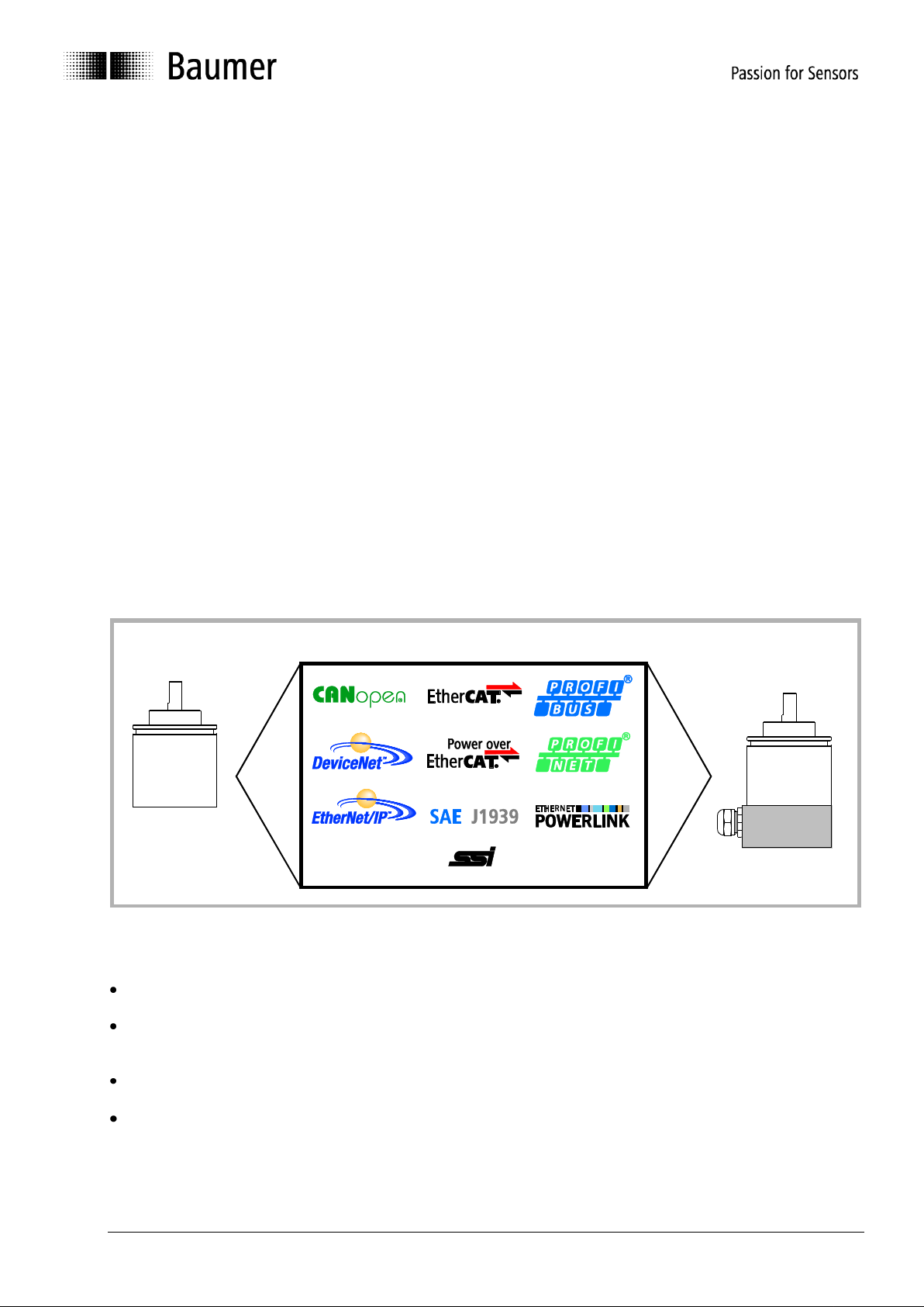
The product family architecture is modular. Depending on what is required from the encoder, the basic
encoder and bus covers can be combined at will with the selected bus system.
The basic encoders differ in terms of accuracy, ambient conditions and the utilized sensing principle.
Bus cover
The bus cover accommodates the field bus interface and the complete electronics for processing the
measured values. EtherNet/IP communication is performed via the specialized EtherNet/IP-ASIC ERTEC200
with integrated high-performance microcontroller ARM9.
Magres / magtivo®
Utilizes a magnetic sensing principle and endures harsh industrial environments.
Procoder / multivo®
Utilizes a photoelectric sensing principle and is the recommended product for precise applications.
Dignalizer / activo® / multivoPlus®
Utilizes a photoelectric sensing principle with integrated analog/digital signal conversion and is the product to
choose for ultra-precise sensing applications.
The bus covers differ by the respectively integrated bus interface.
Available bus interfaces: CANopen, DeviceNet, EtherCAT, Ethernet/IP, Profibus-DP, Profinet, Powerlink,
Power over EtherCAT, SAE J1939, SSI.
All encoders enable parameterization by bus interface.
Functional principle:
Speed signal
Baumer Profibus encoders with bus cover concept permit readout of the current rotary speed. There are four
different scaling systems available:
Manual_ProfibusDPV0_BIDE_EN.docx 6/26 Baumer IVO GmbH & Co. KG
22.11.12 Villingen-Schwenningen, Germany
RPM
Readout of the speed in revolutions per minute.
Steps/s
Readout of the speed in units of the parameterized singleturn resolution per second. The speed is
measured over a period of 200 ms in each case and then updated.
Steps/100 ms
Readout of the speed in units of the parameterized singleturn resolution per 100 ms.
Steps/10 ms
Readout of the speed in units of the parameterized singleturn resolution per 10 ms.
Page 7

4. Profibus-DP
General
Bus systems are connecting structures which generate communication between several components.
The Profibus-DP is a manufacturer-independent open communication system for applications in the fields of
production, process and building automation. It is broken down into three variants:
Profibus FMS for data communication between control units on the production and process management
level.
Profibus PA for process engineering applications.
Profibus DP for fast data exchange between control units and decentral peripherals in automation
engineering applications.
The Profibus system comprises the following device types:
DP master class 1 (DPM1) is a control system which cyclically exchanges information with a DP slave.
DP master class 2 (DPM2) are programming or project processing devices or controllers.
DP slave is a peripheral device which receives output data and forwards input data to the programmable
logic controller.
The Profibus system is broken down into a monomaster system and a multimaster system by the number of
active masters in operation during the operating phase.
In a monomaster system, only one master class 1 and the DP slaves are active in the bus.
In a multimaster system, several masters and the DP slaves are active in the bus. The masters can
optionally either belong to class 1 or class 2.
The Profibus DP is characterized by the following features:
Short response times (1 ms with 32 users and 12 MBaud)
Reliable transmission procedure (Hamming distance 4)
Availability of a wide range of standardized system components
Good diagnostic capability
Simple handling and facility for upgrading
User-oriented bus system
Open system
Profibus-DP is standardized by standard EN 50170 Vol. 2. This standard defines the communication and user
profiles. The user profile for interface converters is profile 1.1. The user profile is differentiated depending on
the number of supported functions according to device class 1 and 2. Device class 2 has a greater number
and contains all the functions of class 1. Parameterization and preset functions are supported only by class 2.
The device supports classes 1 and 2.
GSD file
The device master data file (GSD file) is a descriptive file which describes all the encoder data required for
operation. The data itself is filed in the ROM of the encoder. The data can be subdivided into two sections.
General definitions contain information such as the manufacturer's name, product designation, Ident.
number, Profibus-specific parameters and baud rates.
Application-related definitions include configuration possibilities, parameters, parameter descriptions,
hardware and software status and diagnostic possibilities.
The format and content are defined in line with the EN 50170 standard.
The GSD file has the ident no. 059B for all the described products. This GSD file is an essential condition for
parameterization and configuration of the encoder with a configuration tool.
Manual_ProfibusDPV0_BIDE_EN.docx 7/26 Baumer IVO GmbH & Co. KG
22.11.12 Villingen-Schwenningen, Germany
Page 8

5. Encoder operating parameters
Parameter
Significance
Sense of rotation
Behaviour of the output code depending on the sense of rotation of the shaft seen
looking at the flange
CW = Increasing values with clockwise rotation
CCW = Increasing values with counterclockwise rotation
Resolution
Number of steps per revolution, input in integral steps
Measurement range
Total resolution = number of steps per revolution x number of revolutions,
input in integral steps
Preset value
A certain output value is assigned to the current position value (referencing)
Parameter
Value range
Default setting
Data type
Sense of rotation
CW/CCW
CW
Octet string
Resolution
1 to 4096 – magtivo
1 to 8192 – multivo
1 to 262144 – activo/multivoPlus
4096
8192
262144
Unsigned 32
Measurement range
1 to 67108864 (226) – magtivo
1 to 536870912 (229) – multivo
1 to 2147483648 (231)
– activo/multivoPlus
67108864
536870912
2147483648
Unsigned 32
Preset value
0 to (measurement range - 1 step)
0
Unsigned 32
Description of operating parameters
Operating parameter values
Manual_ProfibusDPV0_BIDE_EN.docx 8/26 Baumer IVO GmbH & Co. KG
22.11.12 Villingen-Schwenningen, Germany
Page 9

6. Data exchange between Profibus-DP devices
DP Master
Triggering telegram
DP Slave
Footer info
Output data
Header info Reply telegram
Header info
Input data
Footer info
6.1. Telegram structure
The diagram illustrates the telegram structure.
Telegram structure
6.2. Initialization, restarting and user data communication
Before an exchange of useful information between the master and slave, every slave is re-initialized. The
master transmits parameterization and configuration data to the slave. Only when the parameterization and
configuration data is in agreement with the data stored in the slave can user data be exchanged. This takes
place in the following way:
Diagnostic request from the master
The master transmits a Diagnosis Request to a slave (Slave_Diag), and the slave responds with a Slave
Diagnosis Response.
The master uses this data to check whether the slave exists in the bus and is ready for parameterization and
configuration.
Parameterization of the slave
The master transmits a Parameter Request to the slave (Set_Prm).
The Slave receives information about the current bus parameters, surveillance times and slave-specific
parameters via the parameterization data. The parameters are taken over during the project processing
phase partially directly or indirectly from the GSD file. The slave compares this parameterization data with its
own stored data.
Configuration of the slave
The master transmits a Check Configuration Request (Chk_Cfg).
The master informs the slave of the scope (number of data bytes) and the structure (data consistency) of the
input and output ranges to be exchanged. The slave compares this configuration with its own configuration.
Diagnosis request prior to data exchange
The master transmits another Slave Diagnosis Request (Slave_Diag), the slave answers with a Slave
Diagnosis Response.
The master now checks whether the parameterization and configuration agree with the data stored in the
slave. If the data requested by the master is admissible and if no error exists, the slave signals its readiness
for the transfer of user data by means of the diagnosis data.
Data_Exchange
The slave now responds exclusively to the master which has parameterized and configured it.
The master transmits a user data request (Data_Exchange), the slave answers with a user data response. In
this response, the slave informs the master whether current diagnosis results are available. The slave only
makes known the actual diagnosis and status information after the master's diagnosis telegram.
Manual_ProfibusDPV0_BIDE_EN.docx 9/26 Baumer IVO GmbH & Co. KG
22.11.12 Villingen-Schwenningen, Germany
Page 10

7. Parameterization and configuration
Device
class
Parameter
Octet no.
Significance
1
Station status
1
Definition of Profibus-specific data
Sync mode/freeze mode active
Response monitoring active
Master assigned
1
Response monitoring time
2 to 3
Recognition of master failure, master must respond
within this period
1
Min. station delay responder
(tsdr)
4
Minimum time which the slave must wait until it may
respond to a request by the master
1
Ident_number
5 to 6
Device identifier which must be unique for each type
of device, saved and reserved by the PNO
1
Group_ident_number
7
Profibus-specific data
1
Operating parameter
8
Profibus-specific data
1
Operating parameter
9
Definition of application-specific data
Counting direction
Functional scope of the encoder, defined in
appliance class 1 and 2
Scaling function
2
Single-turn resolution
10 to 13
Definition of the number of measurement steps per
revolution
2
Total resolution in steps
14 to 17
Definition of the total resolution in steps
Total resolution is the number of measurement
steps x the number of revolutions
2
Scaling the speed signal
26
Definition of the unit of measurement in which the
speed signal (if selected) is read out (e.g. rpm)
7.1. Parameterization
Parameterization refers to the transfer of information which the slave requires for exchanging process data.
The information comprises Profibus-specific data (Octets 1 to 6) and user-specific information. The userspecific information can be entered via an input window during the project processing phase.
The slave compares the data transmitted by the master with the data it has stored. However, the slave does
not inform the master of the result until the diagnosis request following configuration.
Description of parameters for the parameterization function (Set_Prm)
Manual_ProfibusDPV0_BIDE_EN.docx 10/26 Baumer IVO GmbH & Co. KG
22.11.12 Villingen-Schwenningen, Germany
Page 11

Value of parameters of the parameterization function (Set_Prm)
Device
class
Parameter
Data type
Octet
no.
Value range
Default value
In the GSD file
1
Station status
Octet
string
1
Sync and freeze
mode supported
Supported baud
rates
1
Response monitoring time
Octet
string
2 to 3
Profibus-specific data
1
Minimum Station Delay
Responder
Octet
string
4
Baud rate dependent
1
Ident number
Octet
string
5 to 6
059B
1
Group ident no.
Octet
string
7
00
1
Operating parameter
Octet
string
8
Profibus-specific data
1
Operating parameter
Octet
string
9
Bit 0 = 0/1 CW/CCW
Bit 1 = 0/1 Device
class 2 off/on
Bit 3 = 0/1 Scaling
function off/on
CW
Class 2
Device class 2 on
Scaling function on
2
Signal turn resolution
Unsigned
32
10 to 13
Octet 10 is MSB
1 to 1024 – magtivo
1 to 8192 – multivo
1 to 262144
– activo/multivoPlus
1024
8192
262144
2
Total resolution in steps
Unsigned
32
14 to 17
Octet 14 is MSB
1 to 67108864 (226)
– magtivo
1 to 536870912 (229)
– multivo
1 to 2147483648(231)
– activo/multivoPlus
67108864
536870912
2147483648
2 Reserved (system-specific)
18 to 25
0
2
Scaling Speed signal
Octet
string
26
0 to 3
0: steps/s
1: steps/100 ms
2: steps/10 ms
3: RPM
3
Manual_ProfibusDPV0_BIDE_EN.docx 11/26 Baumer IVO GmbH & Co. KG
22.11.12 Villingen-Schwenningen, Germany
Page 12

Important note for multiturn encoder operation
This encoder supports „Endless Operation“ automatically if required.
Thus, there are no special requirements for the encoder parameters “total measuring range” and “measuring
units per revolution” to stand in a certain ratio.
With endless operation active, the encoder shaft must not rotate when the encoder is not powered. In
those cases where powerless motion cannot be avoided, the encoder has to be referenced (presetted) after
each power-up. With Endless Operation inactive, the encoder shaft may rotate unlimited when encoder not
powered.
How to determine if „Endless Operation“ is in use:
Multiply the encoder’s „max. possible revolutions“ (depending on encoder 16 bit = 65536 or 13 bit =
8192) by your chosen parameter „measuring units per revolution“.
Divide this value by your chosen „total measuring range“.
If there is a division remainder, endless operation is in use.
Example for parameters without endless operation:
Maximum possible revolutions 65536 (16 bit multiturn)
Measuring units per revolution 3600
Total measuring range 29.491.200 (8192 x 3600)
Calculation: 65536 x 3600 / 29.491.200 = 8 (no remainder)
Example for parameters with endless operation:
Maximum possible revolutions 65536 (16 bit multiturn)
Measuring units per revolution 3600
Total measuring range 100.000
Calculation: 65536 x 3600 / 100.000 = 2359 remainder 29600
Manual_ProfibusDPV0_BIDE_EN.docx 12/26 Baumer IVO GmbH & Co. KG
22.11.12 Villingen-Schwenningen, Germany
Page 13

7.2. Configuration
Device
Class
Configuration
Significance
1
D1h
2 words input data with data consistency for position values to max. 31 bit
2
F1h
2 words output data with data consistency for preset value to max. 31 bit
2 words input data with data consistency for position values to max. 31 bit
1
D0h
1 word input data with data consistency for position values to max. 15 bit
2
F0h
1 word output data with data consistency for preset values to max. 15 bit
1 word input data with data consistency for position values to max. 15 bit
1
D1h, D0h
2 words input data with data consistency for position values to max. 31 bit
1 word input data with data consistency for speed values to max. 16 bit
2
F1h, D0h
2 words output data with data consistency for preset value to max. 31 bit
2 words input data with data consistency for position values to max. 31 bit
1 word input data with data consistency for speed values to max. 16 bit
1
D0h, D0h
1 word input data with data consistency for position values to max. 15 bit
1 word input data with data consistency for speed values to max. 16 bit
2
F0h, D0h
1 word output data with data consistency for preset values to max. 15 bit
1 word input data with data consistency for position values to max. 15 bit
1 word input data with data consistency for speed values to max. 16 bit
Configuration refers to the definition of type, length and data direction of the process data, as well as the way
in which the data is further processed. The type stipulates the data type and whether the data is contiguous
(consistent). The length determines the number of data bytes available for use. The data direction defines
whether data is transferred from master to slave or vice versa. The encoder is able to read preset values or
transmit position values and if applicable also transmit speed values. The length is optionally 1 or 2 words,
and the data is consistent in both cases. The configuration is compared with the configuration stored in the
slave. The slave informs the master of the result in the following diagnosis request.
The position values of the encoder from the view point of the master are input data, preset values and output
data.
Admissible configurations
Manual_ProfibusDPV0_BIDE_EN.docx 13/26 Baumer IVO GmbH & Co. KG
22.11.12 Villingen-Schwenningen, Germany
Page 14

8. Diagnostic signals
Device
class
Diagnosis data
Octet no.
Significance
1
Station status 1
1
Status of
Parameterization
Configuration
Diagnostic data (Diag.ext. bit and Diag.stat. bit in case of
alarm and warning signals)
1
Station status 2
2
Status of
Response monitoring
Freeze or Sync mode
1
Station status 3
3
Not supported
1
Diag_Master
4
Address of the master which first parameterized the slave
1
Ident_number
5 to 6
Device identifier
Unique for each device type
Reserved and stored with the PNO
1
Extended diagnosis
header
7
Length of the encoder diagnosis including diagnosis header
byte in the case of extended diagnosis
1
Alarm signals
8
Display of malfunctions which could lead to incorrect position
values.
Triggered by
Code consistency error or inadmissible preset value
Preset value is outside the admissible value range.
1
Operating status
9
Indication of supported user-specific data
Counting direction
Functional scope of the encoder, defined in device class 1
and 2
Extended diagnosis
Scaling function
1
Encoder type
10
Indication of encoder type
1
Steps per revolution
11 to 14
Maximum resolution per revolution of the encoder
1
Number of revolutions
15, 16
Maximum number of revolutions of the encoder
2
Additional alarm
signals
17
Not supported
2
Supported alarm signals
18
Indication of which alarm is supported
Incorrect position value
Diagnostic signals contain data relating to the respective status of the encoder. The diagnostic signals
comprise Profibus-relevant information and device-specific information. The master controls communication
with the slave using this information, or forwards it to the higher-level system.
The master requests diagnosis data both prior to parameterization and after configuration of the slave.
This ensures that the slave is present in the bus and that the data stored in the control system software is in
agreement with the data stored in the slave. The slave can also register a diagnosis event in the
Data_Exchange mode. The master then requests the diagnosis data. The user-specific information is defined
in the EN 50170 standard under Encoder profile 1.1.
The display element integrated in the bus cover (dual red/green LED) indicates part of this information.
8.1. Description of the diagnosis data Slave_Diag
Continued on next page.
Manual_ProfibusDPV0_BIDE_EN.docx 14/26 Baumer IVO GmbH & Co. KG
22.11.12 Villingen-Schwenningen, Germany
Page 15

Description of diagnosis data Slave_Diag (contd.)
Device
class
Diagnosis data
Octet no.
Significance
2
Warnings
20, 21
Indicates when parameters are not within the admissible
tolerance. In contrast to alarm signals, these events do not
result in incorrect position values.
Voltage of the lithium cell has dropped below the critical
value (only multiturn encoders)
2
Supported warning
signals
22, 23
Indicates which warning signal is supported
Voltage of the lithium cell has dropped below the prescribed
value (only multiturn encoders)
2
Profile version
24, 25
Profile version of the encoder profile in revision number and
index
2
Software version
26, 27
Indicates the software version in revision number and index,
identical to the indication on the rating plate of the encoder.
2
Operating hours counter
28 to 31
Not supported
2
Offset value
32 to 35
Indicates the offset value stored in the EEPROM after a
preset
2
Manufacturer offset
36 to 39
Not supported, reserved for servicing purposes
2
Steps per revolution
40 to 43
Indicates the programmed steps per revolution of the encoder
2
Total resolution in steps
44 to 47
Indicates the programmed total resolution in steps of the
encoder
2
Serial number
48 to 57
Not supported
2
Reserved
58, 59
Not supported, reserved for servicing purposes
Manual_ProfibusDPV0_BIDE_EN.docx 15/26 Baumer IVO GmbH & Co. KG
22.11.12 Villingen-Schwenningen, Germany
Page 16

Alarm signal position error
The alarm signal is triggered by two events:
Code consistency error due to a malfunction in the optoelectronic/magnetic system
Preset value outside the admissible value range
The angular position of the shaft is sampled cyclically via the encoded glass panel. Two
consecutive position values are compared to each other. If the value change exceeds a
certain number of steps, the last position value is implausible.
The encoder sets the Ext_diag. bit and bit 0 to the alarm signal status.
In case of a code consistency error, the Ext_diag. bit is automatically reset after 2.5 s. If a
further event occurs during this time, the period is automatically extended by 2.5 s.
In the event of an inadmissible preset value, the Ext_diag bit remains set until the master has
transmitted the correct value.
Code consistency errors and inadmissible preset values are indicated by the display element
in the bus cover.
If the encoder is receiving no operating voltage, the internal lithium cell supplies the necessary
supply voltage for the part of the circuit necessary for counting revolutions and storing them in
the ASIC. When the operating voltage is switched on, the stored value is read out, the position
change within one revolution is picked up by the optoelectronic or magnetic singleturn system.
Position changes in the OFF status are brought about for example by run-on of the shaft or
subsequent manual adjustment.
The lithium cell voltage is internally monitored. If the voltage drops below the prescribed value,
the encoder internally sets the Diag_ext error bit and indicates the event via bit 5 in the warning
signal. However, the revolution counting and saving functions are only guaranteed for a certain
time when powered by the lithium cell.
Once this period is exhausted, the encoder must be decommissioned or permanently powered
by an external voltage supply.
The amount of time for which the encoder can continue to be operated depends on recognition
of the event.
Status signal already exists at encoder power on.
If the time of first occurrence is not known, the encoder must be withdrawn from service
immediately.
Status signal occurs during operation in the Data_Exchange mode.
Once the status signal is active, the encoder will continue to function for several weeks
without problems before it needs to be exchanged.
Warning signal lithium cell voltage (only multiturn encoders)
Manual_ProfibusDPV0_BIDE_EN.docx 16/26 Baumer IVO GmbH & Co. KG
22.11.12 Villingen-Schwenningen, Germany
Page 17

8.2. Parameter values of the diagnosis data Slave_Diag
Device
class
Diagnostic data
Data type
Octet no.
Value range
1
Station status
Octet string
1 to 3
Profibus-specific data
1
Diag_master
Octet string
4
Profibus-specific data
1
Ident_number
Octet string
5 to 6
059B
1
Extended diagnosis
Octet string
7
16 byte with class 1
57 byte with class 2
1
Alarm signals
Octet string
8
Bit 0 = 1 position error
1
Operating status
Octet string
9
Bit 0 = 0 Cw
Bit 0 = 1 Ccw
Bit 1 = 1 (Encoder supported Class 2
Functionality)
Bit 3 = Scaling function on/off
1
Encoder type
Octet string
10
01h = Multiturn / 00h = Singleturn
1
Singleturn resolution
Unsigned
32
11 to 14
Octet 11 is MSB
1 to 4096 – magtivo
1 to 8192 – multivo
1 to 262144 – activo/multivoPlus
1
Number of revolutions
Unsigned
16
15, 16
Octet 15 is MSB
1 to 65535 – magtivo
1 to 65535 – multivo
1 to 8192 – activo/multivoPlus
2
Additional alarm signals
Octet string
17
Not supported
2
Supported alarm signals
Octet string
18, 19
Octet 19
Bit 0 = 1 Position error supported
2
Warnings
Octet string
20, 21
Octet 21
Bit 5 = 1 Lithium cell voltage drops below
specified value (only multiturn encoder)
2
Supported warning signals
Octet string
22, 23
Octet 2 is MSB
Bit 5 = 1 lithium cell voltage (only multiturn
encoder) supported
2
Profile version
Octet string
24, 25
Encoder profile 1.10
2
Software version
Octet string
26, 27
Additional stored on the rating plate
2
Hours-run counter
Octet string
28 to 31
Not supported
2
Offset value
Octet string
32 to 35
Dependent on preset value
2
Manufacturer offset
Octet string
36 to 39
Not supported
2
Steps per revolution
Unsigned
32
40 to 43
Octet 40 is MSB
1 to 4096 – magtivo
1 to 8192 – multivo
1 to 262144 – activo/multivoPlus
2
Total resolution in steps
Unsigned
32
44 to 47
Octet 44 is MSB
1 to 67108864 (226) – magtivo
1 to 536870912 (229) – multivo
1 to 2147483648(231) – activo/multivoPlus
2
Serial number
ASCII string
48 to 57
Not supported,
all digits (Octet) "*" corresponds to "2Ah"
2
Reserved
Octet string
58, 59
Reserved for servicing purposes
Manual_ProfibusDPV0_BIDE_EN.docx 17/26 Baumer IVO GmbH & Co. KG
22.11.12 Villingen-Schwenningen, Germany
Page 18

8.3. User data
Conversely to diagnostic data, user data is data which refers to the process being monitored or controlled. In
the case of this encoder, this data takes the form of the position and where applicable the speed which the
Profibus transmits to the control system (master), and in the other direction a preset value with which the
encoder (slave) can be pre-set to a certain position value.
User data is exchanged in the Data_Exchange mode. The framework conditions for the exchange (e.g.
encoder resolution, word length) are previously defined in the configuration.
The slave can also indicate the presence of a diagnosis event during data exchange. The master then
requests diagnostic and status information by means of a diagnosis request.
In order to set a preset, the master transmits the preset value (depending on the configuration either 16 or 32
bit) to the slave (see "preset function").
In the "Data Exchange" status, the dual LED lights up continuously in green on the bus cover.
8.4. Preset function
The preset function is only available in the encoder's "Class2" operating mode.
The control system can transmit a preset value to the encoder and so set the encoder, given a prescribed
mechanical position, to a certain position value. The preset value must lie within the programmed overall
measurement range.
To ensure optimum coordination between the mechanical position and the preset value, the preset value
should only be set when the encoder is at a standstill. However, where the requirements are not particularly
stringent, this can also be performed during rotary movement.
In order to set a preset, the control system transmits the preset value twice to the encoder: Once with the
most significant bit (MSB) set and then again with the MSB reset. In this way, the MSB acts in a certain
manner as a "clock" bit. For this reason, the transmitted preset value is limited to the value range up to 15 bit
(encoder class 2, 16 bit) or 31 bit (encoder class 2, 32 bit).
The first transmission is authoritative in determining the time of acceptance.
Example: Zeroing the encoder (preset value = 0, encoder class 2, 32 bit)
Step 1: Control transmits 80000000h (preset adoption)
Step 2: Control transmits 00000000h (control bit return)
The encoder calculates an offset value for internal purposes from the differential between the current position
and preset value. This value generally has no bearing on the application, but can be read out if required
among the diagnostic data.
The offset value is stored on a non-volatile basis in an EEPROM chip. The EEPROM is capable of at least 1
million write cycles. However, despite the high number of possible write cycles, frequent program or eventcontrolled preset setting could mean reaching the service life limit. A certain degree of care is therefore called
for when designing the control software at this point.
Manual_ProfibusDPV0_BIDE_EN.docx 18/26 Baumer IVO GmbH & Co. KG
22.11.12 Villingen-Schwenningen, Germany
Page 19

9. Entering parameters
Total resolution
= 3600 steps per revolution x
256 revolutions
= 921600
Conversion into hexadecimal format
= E1000
Subdivision into “hi”
= 000E
Conversion into decimal format
= 14
Subdivision into “lo”
= 1000
Conversion into decimal format
= 4096
Total measuring range (units) hi
= 14
Total measuring range (units) lo
= 4096
Steps per revolution
= 3600 steps
= 3600
Measuring units per rev. hi
= 0
Measuring units per rev. lo
= 3600
The following parameter data is stored in the GSD file in the form of 32-bit values
(double words, format "unsigned32"):
- Steps per revolution
- Total resolution
Many configuration programs for Profibus masters (including also Step7® from SIEMENS) do not support this
word length during parameter input. The upper and lower 16 bits of these parameters ("hi" and "low" block)
must accordingly be entered separately, and in decimal form.
In the case of parameters smaller than 65535 (16 bit), all that is necessary is to enter the block "hi" = 0 and
the parameter itself is entered directly in the "lo" block.
Parameters greater than 65535 (16 bit), must be separated beforehand using the formula described below
and then recalculated. A calculator with hexadecimal function of the type provided among the "Windows
accessories" is helpful here.
Conversion of the required parameter value from the decimal format into hexadecimal format
Subdivision of the hexadecimal value into two blocks, "hi" and "lo". The block length in each case is two
words
Conversion of the hexadecimal format of the two blocks "hi" and "lo" back into decimal format
Input into the input mask using the decimal format
Example
Manual_ProfibusDPV0_BIDE_EN.docx 19/26 Baumer IVO GmbH & Co. KG
22.11.12 Villingen-Schwenningen, Germany
Page 20

Example for entering parameters
Manual_ProfibusDPV0_BIDE_EN.docx 20/26 Baumer IVO GmbH & Co. KG
22.11.12 Villingen-Schwenningen, Germany
Page 21

10. Terminal assignment and commissioning
Example: 23
10.1. Mechanical mounting
Shaft encoder
Mount the encoder housing using the fastening holes on the flange side with three screws (square flange
with four screws), paying attention to the thread diameter and thread depth.
Alternatively, the encoder can be mounted in any angular position using three eccentric fastenings - see
accessories.
Connect the drive shaft and encoder shaft using a suitable coupling. The ends of the shafts must not be
touching. The coupling must be capable of compensating for displacement due to temperature and
mechanical backlash. Pay attention to the admissible axial or radial shaft loads. For suitable connecting
devices, see under accessories.
Tighten the fastening screws
End shaft / Hollow shaft encoder
Clamping ring fixture
Prior to mounting the encoder open the clamping ring completely. Push encoder onto the drive shaft and
tighten the clamping ring firmly.
Encoder torque pin
Slide encoder onto the drive shaft and insert torque pin into the adjusting element provided by customer.
Adjusting element with rubberized spring element
Push the encoder on to the drive shaft and insert the parallel pin into the mounted adjusting element (not
supplied) (with rubberized spring element)
Adjusting bracket
Push the encoder over the drive shaft. Insert the adjusting bracket into the rubberized spring element of
the encoder and fasten the adjusting bracket on the contact surface (not supplied).
Shoulder screw
Push the encoder over the drive shaft and insert the shoulder screw (not supplied) in the rubberized spring
element of the encoder.
Coupling spring
Mount the coupling spring with screws onto the fixing holes of the encoder housing.
Push the encoder over the drive shaft and fasten the coupling spring on the contact surface.
10.2. Electrical connection
Only ever store or transport the bus cover in the ESD bag. The bus cover must rest fully against the housing
and be firmly screwed in place.
For electrical connection, pull off the bus cover using the following method:
Release the fastening screws of the bus cover
Carefully loosen the bus cover and lift off in the axial direction
10.2.1. Setting the user address
The user address is set decimally using two rotary switches in the bus cover.
The maximum number of users is 99. The address is read in once during power-up.
Set the user address decimally using the two rotary switches 1 and 2 (default setting 00).
Manual_ProfibusDPV0_BIDE_EN.docx 21/26 Baumer IVO GmbH & Co. KG
22.11.12 Villingen-Schwenningen, Germany
Page 22

10.2.2. Terminating resistor
both ON = Final user
both OFF = user X
Terminal
Resistor
A to GND
390 Ohm
B to +5 V
390 Ohm
A to B
220 Ohm
Bus cable
Supply voltage cable
If the connected encoder is the last one in the bus line, the bus must be terminated with a resistor.
The resistors are integrated in the bus cover and are connected using a two-pole DIP switch.
The internal terminating resistors must be set to "ON" in the last user with the two-pole DIP switch
(default setting OFF).
10.2.3. Bus cover connection
Release the cap nut of the cable gland.
Push the cap nut and seal insert with contact sleeve onto the cable sheath.
Strip the cable sheath and cores, shorten the shield film where this exists (see Fig.)
Bend over the braided screen by approx. 90°.
Push the sealing insert with contact sleeve along as far as the braided shield. Insert the sealing insert
with contact sleeve and cable flush into the cable gland and tighten the cap nut.
For standard encoder
For G0AMH, G0MMH, GBAMH and GBMMH
Terminals with the same designation are internally interconnected.
For the power supply, use only cable gland 3. For the bus lines, cable gland 1 or 2 can be optionally
selected. For the bus lines, cable glands 1 or 2 can be freely selected. Observe the admissible cable
cross sections.
Insert the cores using the shortest route from the cable gland to the terminal strip. Observe the admissible
core cross-section. Use isolated core end sleeves.
Avoid crossing over data lines with the supply voltage line.
Manual_ProfibusDPV0_BIDE_EN.docx 22/26 Baumer IVO GmbH & Co. KG
22.11.12 Villingen-Schwenningen, Germany
Page 23

Bus cover – shaft/end shaft
1 2 3
Cable gland
M12-connector
1 2 3
Bus cover – hollow shaft G1 and G2
Manual_ProfibusDPV0_BIDE_EN.docx 23/26 Baumer IVO GmbH & Co. KG
22.11.12 Villingen-Schwenningen, Germany
Page 24

Bus cover – hollow shaft G0 and GB
The connection cable is wired to the 8-pin terminal block inside the interface converter.
The additional functions Zero and UP/DOWN provided by the encoder are to be assigned as follows for
optimum interference immunity:
- Zero additionally assigned to GND
- UP/DOWN additionally assigned to UB
The encoder outputs DV, DV-MT may either be cut off and isolated or assigned to the available terminals
NC1(DV) respectively NC2 (DV-MT).
Interface converter - GK410
Manual_ProfibusDPV0_BIDE_EN.docx 24/26 Baumer IVO GmbH & Co. KG
22.11.12 Villingen-Schwenningen, Germany
Page 25

10.2.4. Terminal assignment
Pin
Terminal
Explanation
Pin 1
UB
Supply voltage 10...30 VDC
Pin 3
GND
Ground connection relating to UB
Pin 2
A
Negative serial data line
Pin 4
B
Positive serial data line
M12-connector
For serial data line
for supply voltage
male female
Colour
Status
Green alight
Encoder in "Data_Exchange" mode
Yellow alight
Encoder ramping up
Red alight for 2.5 s
Wrong position value, caused by code constancy error
Red flashing, 1 Hz
Parameterization error
Red flashing, 5 Hz
Transmitted preset value in inadmissible value range
Terminals with the same significance are internally connected and identical in their functions. Max. load on
the internal terminal connections UB-UB and GND-GND is 1 A.
A and B are each isolated for 12 MBaud operation with an inductivity of 100 nH
Carefully plug the bus cover onto the D-SUB plug of the basic encoder, then press only via the sealing
rubber, taking care not to tilt it. The bus cover must rest fully against the basic encoder.
Tighten both the fastening screws firmly in the same direction.
The encoder housing and braided shield of the connecting cable are only ideally connected if the bus cover is
resting fully on the basic encoder (positive locking).
10.3. Display element (status display)
A dual LED is integrated at the back of the bus cover.
Manual_ProfibusDPV0_BIDE_EN.docx 25/26 Baumer IVO GmbH & Co. KG
22.11.12 Villingen-Schwenningen, Germany
Page 26

10.3.1. Profibus cable
Features
Data
Shaft resistance in Ohm
135 to 165 at 3 to 20 MHz
Operating capacity (pF/m)
Less than 30
Loop resistance (Ohm/km)
Less than 110
Core diameter (mm)
Greater than 0.64
Core cross section (mm)
Greater than 0.34
Baud rate in
kBaud
9.6
19.2
93.75
187.5
500
1500
3000
12000
Cable length
in m
1200
1200
1200
1000
400
200
100
100
EN 50170 specifies two types of cable, A and B. Cable type B is obsolete and should no longer be used for
new applications. With cable type A, all transmission rates up to 12 MBaud can be used.
Transmission speed depending on cable length
Manual_ProfibusDPV0_BIDE_EN.docx 26/26 Baumer IVO GmbH & Co. KG
22.11.12 Villingen-Schwenningen, Germany
 Loading...