

Page 1

Manual
Absolute Encoder with CANopen
Firmware version from 1.00
Baumer IVO GmbH & Co. KG
Dauchinger Strasse 58-62
DE-78056 Villingen-Schwenningen
Phone +49 7720 942-0
Fax +49 7720 942-900 11.12 · 174.02.030/9
info.de@baumerivo.com Subject to modification in technic and design.
www.baumer.com Errors and omissions excepted.
Page 2

Contents
Page
1. Introduction 3
1.1. Scope of delivery 3
1.2. Product assignment 3
2. Safety and operating instructions 4
3. CAN bus and CANopen communication 5
3.1. CAN bus 5
3.1.1. CAN bus characteristics 5
3.2. CANopen 6
3.3. CANopen communication 7
3.3.1. Communication profile 7
3.3.2. CANopen message structure 7
3.3.3. Service data communication 8
3.3.4. Process data communication 9
3.3.5. Emergency service 11
3.3.6. Network management services 12
3.4. Encoder profile 19
3.4.1. Overview of encoder objects 19
3.4.2. Detailed object list (DS-301) 23
4. Diagnosis and useful information 39
4.1. Error diagnosis field bus communication 39
4.2. Error diagnosis via field bus 39
4.3. Useful information relating to the sensor 40
5. Applications 41
5.1. Setting and reading objects 41
5.2. Configuration 42
5.3. Operation 43
5.4. Use the encoder via CAN interface 45
6. Terminal assignment and commissioning 47
6.1. Mechanical mounting 47
6.2. Electrical connection 47
6.2.1. Contact description 47
6.2.2. Pin assignment M12 connector 47
6.2.3. Pin assignment D-SUB connector 48
6.3. Display elements (status display) 48
Manual_G0-GB-GXP5-GXU5_406_EN.docx 2/48 Baumer IVO GmbH & Co. KG
20.11.12 Villingen-Schwenningen, Germany
Page 3
Disclaimer of liability
Product
Product code
Device name
Eds file
Product family
GBP5W
0x18
GBP5
GBP5_406.eds
Multiturn
GBU5W
0x19
GBU5
GBU5_406.eds
Singleturn
GXP5W
0x14
GXP5
GXP5_406.eds
Multiturn
GXU5W
0x15
GXU5
GXU5_406.eds
Singleturn
X 700
0x14
GXP5
GXP5_406.eds
Multiturn
Product
Product code
Device name
Eds file
Product family
GBP5S
0x18
GBP5
GBP5_406.eds
Multiturn
GBU5S
0x19
GBU5
GBU5_406.eds
Singleturn
GXP5S
0x14
GXP5
GXP5_406.eds
Multiturn
GXU5S
0x15
GXU5
GXU5_406.eds
Singleturn
Product
Product code
Device name
Eds file
Product family
G0P5H
0x14
GXP5
GBP5_406.eds
Multiturn
GBP5H
0x18
GBP5
GBP5_406.eds
Multiturn
The present manual was compiled with utmost care, errors and omissions reserved. For this reason
Baumer IVO GmbH & Co. KG rejects any liability for the information compiled in the present manual.
Baumer IVO nor the author will accept any liability for direct or indirect damages resulting from the use of the
present information.
At any time we should be pleased receiving your comments and proposals for further improvement of the
present document.
1. Introduction
1.1. Scope of delivery
Please check the delivery upon completeness prior to commissioning.
Depending on encoder configuration and part number delivery is including:
Encoder
CD with describing file and manual (also available as download in the Internet)
1.2. Product assignment
Shaft encoders
End shaft encoders
Hollow shaft encoders
Manual_G0-GB-GXP5-GXU5_406_EN.docx 3/48 Baumer IVO GmbH & Co. KG
20.11.12 Villingen-Schwenningen, Germany
Page 4

2. Safety and operating instructions
Supplementary information
This manual is intended as a supplement to already existing documentation (catalogues, product
information or assembly instructions).
The manual must be read without fail before initial commissioning of the equipment.
Intended purpose of the equipment
The encoder is a precision measurement device. It is used to determine angular positions and
revolutions, and to prepare and supply measured values in the form of electrical output signals for the
follow-on device systems. The encoder may only be used for this purpose.
Commissioning
The encoder may only be installed and assembled by suitably qualified experts.
Observe the operating instructions of the machine manufacturer.
Safety remarks
Prior to commissioning the equipment, check all electrical connections.
If installation, electrical connection or any other work performed at the encoder or at the equipment is not
correctly executed, this can result in a malfunction or failure of the encoder.
Steps must be taken to exclude any risk of personal injury, damage to the plant or to the operating
equipment as a result of encoder failure or malfunction by providing suitable safety precautions.
Encoders must not be operated outside the specified limited values (see detailed product documentation).
Failure to comply with the safety remarks can result in malfunctions, personal injury or damage to property.
Transport and storage
Only ever transport or store encoders in their original packaging.
Never drop encoders or expose them to major vibrations.
Assembly
Avoid impacts or shocks on the housing and shaft / hollow shaft
Avoid any twist or torsion on the housing.
Never make rigid connections between the encoder shaft and drive shaft.
Do not open the encoder or make any mechanical changes to it.
The shaft, ball bearings, glass pane or electronic components can be damaged. In this case, safe and reliable
operation cannot be guaranteed.
Electrical commissioning
Do not make any electrical changes at the encoder.
Do not carry out any wiring work when the encoder is live.
Never plug or unplug the electrical connection when the encoder is live.
Ensure that the entire plant is installed in line with EMC requirements. The installation environment and
wiring affect the electromagnetic compatibility of the encoder. Install the encoder and supply cables
separately or at a long distance from cables with high interference emissions (frequency converters,
contactors etc.)
Where working with consumers which have high interference emissions, make available a separate
power supply for the encoder.
Completely shield the encoder housing and connecting cable.
Connect the encoder to the protective earth (PE) conductor using shielded cable. The braided shield must
be connected to the cable gland or plug. Ideally, aim at bilateral connection to protective earth (PE), the
housing via the mechanical assembly, the cable shield via the downstream connected devices. In case of
earth loop problems, earth on one side only as a minimum requirement.
Failure to observe these instructions can result in malfunctions, material damage or personal injury.
Manual_G0-GB-GXP5-GXU5_406_EN.docx 4/48 Baumer IVO GmbH & Co. KG
20.11.12 Villingen-Schwenningen, Germany
Page 5

3. CAN bus and CANopen communication
3.1. CAN bus
The CAN bus (CAN: Controller Area Network) was originally developed by Bosch and Intel as a means of
fast, low-cost data transmission in automotive applications. The CAN bus is used today also in industrial
automation applications.
The CAN bus is a field bus (the standards are defined by the CAN in Automation (CiA) Association) through
which devices, actuators and sensors from different manufacturers can communicate with each other.
3.1.1. CAN bus characteristics
• Data rate of 1 MBaud with network expansion up to 40 m
• Network connected on both sides
• The bus medium is a twisted-pair cable
• Real time capability: Defined maximum waiting time for high-priority messages.
• Theoretically 127 users at one bus, but physically only 32 are possible (due to the driver).
• Ensures data consistency across the network. Damaged messages are notified as faulty for all network
nodes.
• Message-oriented communication
The message is identified by a message identifier. All network nodes use the identifier to test whether the
message is of relevance for them.
• Broadcasting, multicasting
All network nodes receive each message simultaneously. Synchronization is therefore possible.
• Multimaster capability
Each user in the field bus is able to independently transmit and receive data without being dependent upon
the priority of the master. Each user is able to start its message when the bus is not occupied. When
messages are sent simultaneously, the user with the highest priority prevails.
• Prioritization of messages
The identifier defines the priority of the message. This ensures that important messages are transmitted
quickly via the bus.
• Residual error probability
Safety procedures in the network reduce the probability of an undiscovered faulty data transmission to
below 10
• Function monitoring
Localization of faulty or failed stations. The CAN protocol encompasses a network node monitoring function.
The function of network nodes which are faulty is restricted, or they are completely uncoupled from the
network.
• Data transmission with short error recovery time
By using several error detection mechanisms, falsified messages are detected to a high degree of
probability. If an error is detected, the message transmission is automatically repeated.
In the CAN Bus, several network users are connected by means of a bus cable. Each network user is able to
transmit and receive messages. The data between network users is serially transmitted.
Examples of network users for CAN bus devices are:
• Automation devices such as PLCs
• PCs
• Input and output modules
• Drive control systems
• Analysis devices, such as a CAN monitor
• Control and input devices as Human Machine Interfaces (HMI)
• Sensors and actuators
-11
. In practical terms, it is possible to ensure a 100% reliable transmission.
Manual_G0-GB-GXP5-GXU5_406_EN.docx 5/48 Baumer IVO GmbH & Co. KG
20.11.12 Villingen-Schwenningen, Germany
Page 6

3.2. CANopen
Under the technical management of the Steinbeis Transfer Centre for Automation, the CANopen profile was
developed on the basis of the Layer 7 specification CAL (CAN Application Layer). In comparison with CAL,
CANopen only contains the functions suitable for this application. CANopen thus represents only a partial
function of CAL optimized for the application in hand, so permitting a simplified system structure and the use
of simplified devices. CANopen is optimized for fast data exchange in real time systems.
The organization CAN in Automation (CiA) is responsible for the applicable standards of the relevant profiles.
CANopen permits:
• Simplified access to all device and communication parameters
• Synchronization of several devices
• Automatic configuration of the network
• Cyclical and event-controlled process data communication
CANopen comprises four communication objects (COB) with different characteristics:
• Process data objects for real time data (PDO)
• Service data objects for parameter and program transmission (SDO)
• Network management (NMT, Heartbeat)
• Pre-defined objects (for synchronization, emergency message)
All device and communication parameters are subdivided into an object directory. An object directory
encompasses the name of the object, data type, number of subindexes, structure of the parameters and the
address. According to CiA, this object directory is subdivided into three different parts. Communication profile,
device profile and a manufacturer-specific profile (see object directory).
Manual_G0-GB-GXP5-GXU5_406_EN.docx 6/48 Baumer IVO GmbH & Co. KG
20.11.12 Villingen-Schwenningen, Germany
Page 7

3.3. CANopen communication
Function code
Node ID
4-bit function code
7-bit node ID
Function code
COB ID
NMT
0
SYNC
80h
Function code
COB ID
Emergency
80h + Node ID
PDO1 (tx)1)
180h + Node ID
PDO2 (tx)1)
280h + Node ID
SDO (tx)1)
580h + Node ID
SDO (rx)1)
600h + Node ID
Heartbeat
700h + Node ID
LSS (tx)
1)
7E4h
LSS (rx)
1)
7E5h
1): (tx) and (rx) from the viewpoint of the encoder
COB ID
DLC
Byte 1
Byte 2
Byte 3
Byte 4
Byte 5
Byte 6
Byte 7
Byte 8
Xxx x xx
xx
xx
xx
xx
xx
xx
xx
3.3.1. Communication profile
Communication between the network users and the Master (PC / Control) takes place by means of object
directories and objects. The objects are addressed via a 16 bit index. The CANopen communication profile
DS 301 standardizes the various communication objects. They are accordingly divided into several groups:
• Process data objects PDO for real time transmission of process data
• Service data objects SDO for read/write access to the object directory
• Objects for synchronization and error display of CAN users:
SYNC object (synchronization object) for synchronization of network users
EMCY object (emergency object) for error display of a device or its peripherals
• Network management NMT for initialization and network control
• Layer Setting Services LSS for configuration by means of serial numbers, revision numbers etc. in the
middle
of an existing network
3.3.2. CANopen message structure
The first part of a message is the COB ID (Identifier).
Structure of the 11-bit COB ID :
The function code provides information on the type of message and priority
The lower the COB ID, the higher the priority of the message
Broadcast messages:
Peer to peer messages:
The node ID can be freely selected by means of the CANopen bus between 1 and 127 (if encoder = 0).
The encoders are supplied with the Node ID 1.
This can be changed with the service data object 2101h or using LSS.
A CAN telegram is made up of the COB ID and up to 8 bytes of data:
The precise telegram is outlined in more detail at a later point.
Manual_G0-GB-GXP5-GXU5_406_EN.docx 7/48 Baumer IVO GmbH & Co. KG
20.11.12 Villingen-Schwenningen, Germany
Page 8

3.3.3. Service data communication
COB ID
DLC
Command
Object L
Object H
Subindex
Data 0
Data 1
Data 2
Data 3
SDO command
Description
Data length
22h
Download request
Max. 4 Byte
Transmits parameter to encoder
23h
Download request
4 byte
2Bh
Download request
2 byte
2Fh
Download request
1 byte
60h
Download response
-
Confirms receipt to master
40h
Upload request
-
Requests parameter from encoder
42h
Upload response
Max. 4 byte
Parameter to master with max. 4 byte
43h
Upload response
4 byte
4Bh
Upload response
2 byte
4Fh
Upload response
1 byte
80h
Abort message
-
Encoder signals error code to master
ID
DLC
Byte 1
Byte 2
Byte 3
Byte 4
Byte 5
Byte 6
Byte 7
Byte 8
580h + Node ID
8
80h
Object L
Object H
Subindex
ErrByte 0
ErrByte 1
ErrByte 2
ErrByte 3
The service data objects correspond to the standards of the CiA. It is possible to access an object via index
and subindex. The data can be requested or where applicable written into the object.
General information on the SDO
Structure of an SDO telegram:
An SDO-COB ID is composed as follows:
Master -> Encoder : 600h + Node ID
Encoder -> Master : 580h + Node ID
DLC (data length code) describes the length of the telegram. This is composed as follows:
1 byte command + 2 bytes object + 1 byte subindex + no. of data bytes (0 - 4).
The command byte defines whether data is read or set, and how many data bytes are involved.
An abort message indicates an error in the CAN communication. The SDO command byte is 80h. The object
and subindex are those of the requested object. The error code is contained in bytes 5 – 8.
Byte 8..5 results in the SDO abort message (byte 8 = MSB).
The following messages are supported:
05040001h : Command byte is not supported
06010000h : Incorrect access to an object
06010001h : Read access to write only
06010002h : Write access to read only
06020000h : Object is not supported
06090011h : Subindex is not supported
06090030h : Value outside the limit
06090031h : Value too great
08000000h : General error
08000020h : Incorrect save signature
08000021h : Data cannot be stored
Manual_G0-GB-GXP5-GXU5_406_EN.docx 8/48 Baumer IVO GmbH & Co. KG
20.11.12 Villingen-Schwenningen, Germany
Page 9

SDO examples
COB ID
DLC
Command
Object L
Object H
Subindex
Data 0
Data
1
Data
2
Data
3
600h+node ID
8
40h
04h
60h 0 x x x
x
COB ID
DLC
Command
Object L
Object H
Subindex
Data 0
Data
1
Data
2
Data
3
580h+node ID
8
43h
04h
60h 0 a b c
d
COB ID
DLC
Command
Object L
Object H
Subindex
Data 0
Data
1
Data
2
Data
3
600h+node ID
8
22h
03h
60h 0 a b c
d
COB ID
DLC
Command
Object L
Object H
Subindex
Data 0
Data
1
Data
2
Data
3
580h+node ID
8
60h
03h
60h 0 0 0 0
0
Byte 0
Byte 1
COB ID = 80
0
Request of a value by the master from the slave
A frequent request will be a request for position. Object 6004h
Response by the slave to the request for a value
The position is 4 bytes long, the precise values can be found under object 6004h.
Writing of a value by the master into the slave
Position setting can be performed with preset. Object 6003h
Slave's response to the writing of a value
3.3.4. Process data communication
Process data objects are used for real time data exchange for process data, for example position or operating
status. PDOs can be transmitted synchronously or cyclically (asynchronously). The encoder supports the
PDO1 and the PDO2. Both PDOs supply the current position of the encoder and are defined in the objects
1800h, 1801h, 1A00h, 1A01, 2800h, 2801h and 6200h.
Synchronous
In order to transmit the process data synchronously, a value between 1 and F0h (=240) must be written into
the object 1800h / 1801h Subindex 2. If the value is 3, the PDO is transmitted on every third sync telegram (if
the value 1 is entered, transmission takes place on every sync telegram), as long as there is a 0 written into
the object 2800h / 2801h. If it contains for example a 5, the PDO will continue to be written as before on every
third Sync telegram, but only a total of 5 times. Accordingly, the last PDO is written on the 15th sync
telegram. The counter for the number of PDOs to be transmitted is reset in the event of a position change or
NMT reset, i.e. unless it is changed, the position is transmitted five times. If the position changes, it is
transmitted a further five times.
In synchronous operation, the PDO is requested by the master via the Sync telegram.
Cyclical (asynchronous)
If you wish the PDOs to be transmitted cyclically, the value FEh must be written into the object 1800h / 1801h
Subindex 2. In addition, the cycle time in milliseconds must be entered in the same object subindex 5. The
entered time is rounded off to 1 ms. If the value is stored for 0 ms, the PDOs are not transmitted. The function
is switched off.
The object 2800h / 2801h offers another possibility: If the value is 0, cyclical transmission runs as described
above. If the value is 1, a cyclical test is performed as to whether a change of the value has occurred. If not,
no transmission takes place. If the value is 4, the PDO is transmitted four times with each cycle if there is a
change.
Manual_G0-GB-GXP5-GXU5_406_EN.docx 9/48 Baumer IVO GmbH & Co. KG
20.11.12 Villingen-Schwenningen, Germany
Page 10

Overview
1800h
2800h
Summarized description
Sub2
Sub5
FEh
3ms
0
Cyclical transmission every 3 ms
FEh
5ms
2
Every 5 ms, the PDO is sent twice if there is a change
FEh
0ms
0
Transmit PDO switched off
FEh
0ms
xxx
Transmit PDO switched off
3
xxx
0
Transmit with every third sync telegram
3
xxx
2Bh
On every third sync telegram, but only 43 times in total (=2Bh).
ID
DLC
Byte 1
Byte 2
Byte 3
Byte 4
181h
4
Xx
Xx
Xx
Xx
ID
DLC
Byte 1
Byte 2
Byte 3
Byte 4
281h
4
Xx
Xx
Xx
Xx
In the following table, the different transmission modes for PDOs are summarized:
PDO (Position)
PDO1 telegram structure:
ID : 180h + node ID
Length : 4 DataByte
Byte1 - 4 : Current position in increments
PDO2 telegram structure:
ID : 280h + node ID
Length : 4 DataByte
Byte1 - 4 : Current position in increments
Manual_G0-GB-GXP5-GXU5_406_EN.docx 10/48 Baumer IVO GmbH & Co. KG
20.11.12 Villingen-Schwenningen, Germany
Page 11
3.3.5. Emergency service
COB-ID
DLC
Byte0
Byte 1
Byte 2
Byte 3
Byte 4
Byte 5
Byte 6
Byte 7
80h+Node-ID
8
Error Code
Errorregister
1001h
Alarms 6503h
Warning 6505h
-
00h
01h
Error Code (hex)
Meaning
0000
Error Reset or No Error
1000
Generic Error
5530
EEPROM error (from V1.04+)
6010
Software reset (Watchdog) (from V1.04+)
7320
Position error (from V1.04+)
7510
Internal communication error (from V1.04+)
8130
Life Guard error or Hearbeat error (from V1.04+)
FF00
Battery low (from V1.04+)
Bit
Meaning
0
Generic Error
4
Communication error (V1.04)
7
manufacturer specific (V1.04)
Bit
Meaning
Wert = 0
Wert = 1
0
Position error aktiv
Nein
Ja
Bit
Meaning
Wert = 0
Wert = 1
2
CPU watchdog status
OK
Reset done
4
Battery charge
OK
Battery low
Internal device error or bus problems initiate an emergency message:
Byte 0..1: Error Codes
Byte 2: Error-Register
Byte 3..4 Alarms
Byte 5..6 Warning
Byte 7: not used
Manual_G0-GB-GXP5-GXU5_406_EN.docx 11/48 Baumer IVO GmbH & Co. KG
20.11.12 Villingen-Schwenningen, Germany
Page 12
3.3.6. Network management services
Byte 0
Byte 1
Byte 2
COB ID = 0
Command byte
Node number
Command byte
Description
In state event drawing
01h
Start remote node
1
02h
Stop remote node
2
80h
Enter pre-operational mode
3
81h, 82h
Reset remote node
4, 5
Init
Pre-Operational
Operational
Stopped/Prepared
Power on oder Hardware Reset
132
1
324/5
BootUp Message
4/5
4/5
Network management can be divided into two groups.
Using the NMT services for device monitoring, bus users can be initialized, started and stopped.
In addition, NMT services exist for connection monitoring.
Description of the NMT command
The commands are transmitted as unconfirmed objects and are structured as follows:
The COB ID for NMT commands is always zero. The node ID is transmitted in byte 2 of the NMT command.
Command byte
The node number corresponds to the node ID of the required users. With node number = 0, all users are
addressed.
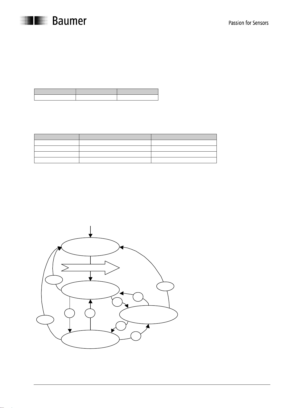
NMT state event
Following initialization, the encoder is in the pre-operational mode. In this status, SDO parameters can be
read and written. In order to request PDO parameters, the encoder must first be moved to the operational
mode status.
Power on or hardware reset
Manual_G0-GB-GXP5-GXU5_406_EN.docx 12/48 Baumer IVO GmbH & Co. KG
20.11.12 Villingen-Schwenningen, Germany
Page 13

The various NMT statuses
COB ID
Byte 0
700h + node ID
00
COB ID
Command byte
Node number
0
1h
0..127
COB ID
Command byte
Node number
0
2h
0..127
COB ID
Command byte
Node number
0
80h
0..127
COB ID
Command byte
Node number
0
81h
0..127
COB ID
Command byte
Node number
0
82h
0..127
Init
Following initalization, the encoder logs on to the CAN bus with a BootUp message. The encoder then goes
automatically to the pre-operational mode status.
The COB ID of the BootUp message is made up of 700h and the node ID.
Pre-operational mode
In the pre-operational mode, SDOs can be read and written.
Operational mode
In the operational mode, the encoder transmits the requested PDOs. In addition, SDOs can be read and
written.
Stopped or prepared mode
In the stopped mode, only NMT communication is possible. No SDO parameters can be read or set. LSS is
only possible in the stopped mode.
Status change
Start remote node (1)
With the start command, the encoder is switched to the operational mode status.
Stop remote node (2)
With the stop command, the encoder is switched to the stopped or prepared mode status.
Enter pre-operational mode (3)
Change to the pre-operational mode status.
Reset remote node (4) or reset communication (5)
With the reset command, the encoder is re-initialized.
Reset remote node (4):
Reset communication (5):
Manual_G0-GB-GXP5-GXU5_406_EN.docx 13/48 Baumer IVO GmbH & Co. KG
20.11.12 Villingen-Schwenningen, Germany
Page 14
Node and Life Guarding
COB-ID
Data/ Remote
Byte 0
701h
r
00h (0d)
701h
d
FFh (255d)
701h
r
00h (0d)
701h
d
7Fh (127d)
"Communication error Object 1029h-1h".
The „CAN in Automation“ association CiA
recommend to use the new heartbeat protocol
(see next chapter).
To use the node guarding instead of heartbeat
protocol bit 5 of object 2110h has to be set.
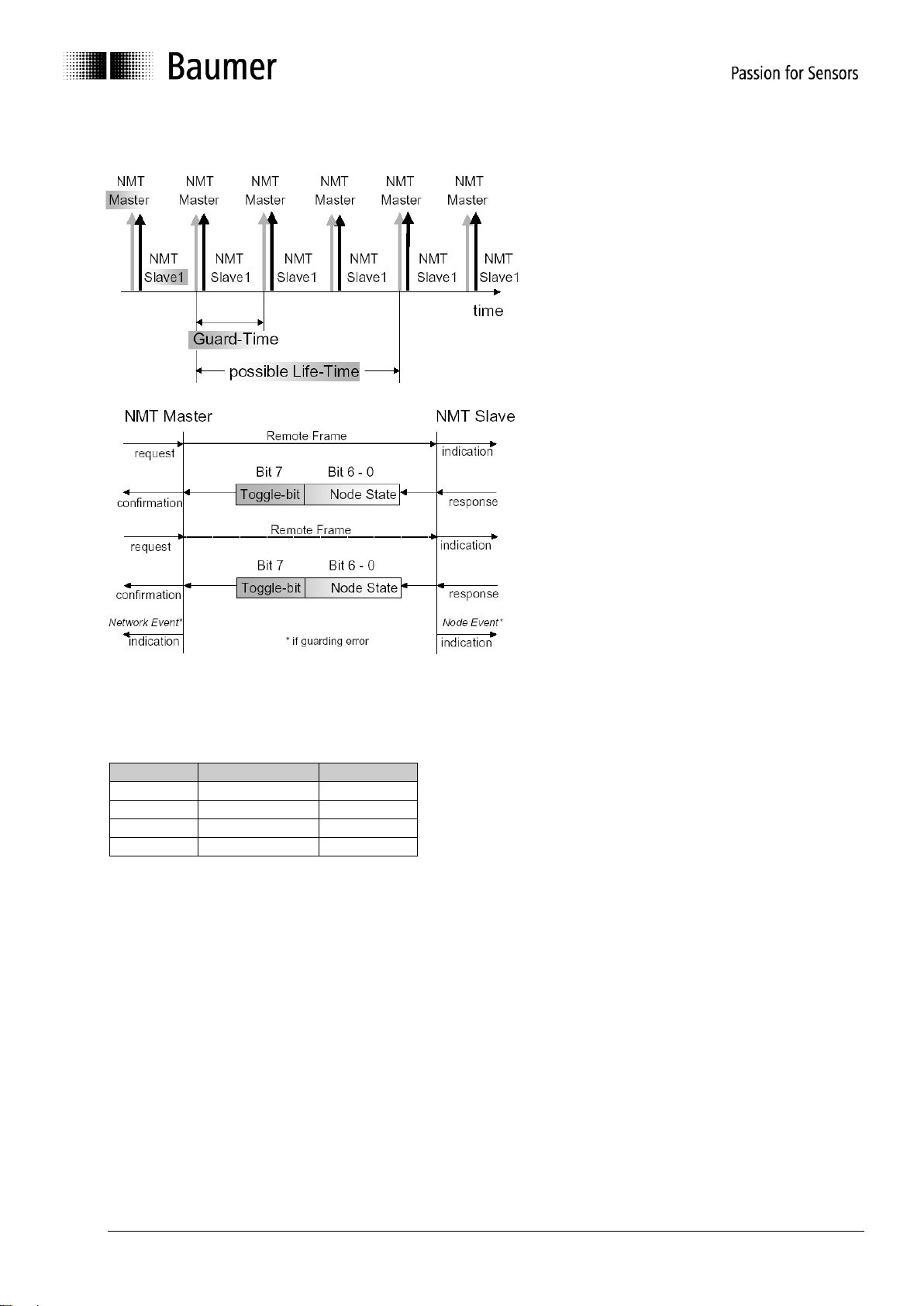
To detect absent devices (e.g. because of
bus-off) that do not transmit PDOs regularly,
the NMT Master can manage a database,
where besides other information the expected
states of all connected devices are recorded,
which is known as Node Guarding. With cyclic
node guarding the NMT master regularly polls
its NMT slaves. To detect the absence of the
NMT master, the slaves test internally,
whether the Node Guarding is taking place in
the defined time interval (Life Guarding). The
Node Guarding is initiated by the NMT Master
in Pre-Operational state of the slave by
transmitting a Remote Frame.
The NMT Master regularly retrieves the actual
states of all devices on the network by a
Remote Frame and compares them to the
states recorded in the network database.
Mismatches are indicated first locally on the
NMT Master through the Network Event
Service. Consequently the application must
take appropriate actions to ensure that all
devices on the bus will got to a save state
Example for a nodeguarding protocol:
Possible NMT node states:
0: BootUp-Event
4: Stopped
5: Operational
127: Pre-operational
in other words, the encoder is in the pre-operational mode (7Fh = 127).
Manual_G0-GB-GXP5-GXU5_406_EN.docx 14/48 Baumer IVO GmbH & Co. KG
20.11.12 Villingen-Schwenningen, Germany
Page 15
Heartbeat protocol
COB-ID
Data/Remote
Byte 0
701h
d
7Fh (127d)
object 1029h-1h".
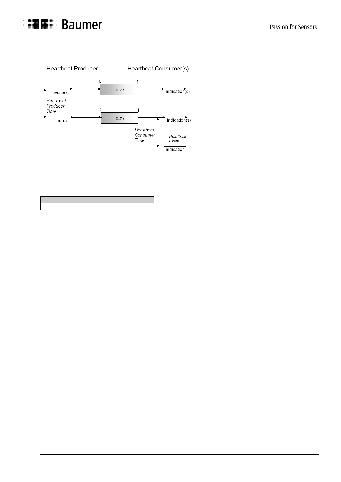
Example for a heartbeat protocol
The optional heartbeat protocol should
substitute the life/node guarding protocol.
Heartbeat ist aktiv, wenn im Objekt 2110h Bit5
auf '0' ist. It is highly recommend to implement
for new device designs the heartbeat protocol.
A Heartbeat Producer transmits the Heartbeat
message cyclically with the frequency defined
in Heartbeat producer time object. One or
more Heartbeat Consumer may receive the
indication. The relationship between producer
and consumer is configurable via Object
Dictionary entries. The Heartbeat Consumer
guards the reception of the Heartbeat within
the Heartbeat consumer time. If the Heartbeat
is not received within this time a Heartbeat
Event will be generated "Communication error
The heartbeat messages consist of the COB ID and one byte. In this byte, the NMT status is supplied.
0: BootUp-Event
4: Stopped
5: Operational
127: Pre-operational
in other words, the encoder is in the pre-operational mode (7Fh = 127).
Attention : Only one each of the above node guarding mechanism can be set.
Default: Heartbeat
Optional: NodeGuarding (see object 2110)
Manual_G0-GB-GXP5-GXU5_406_EN.docx 15/48 Baumer IVO GmbH & Co. KG
20.11.12 Villingen-Schwenningen, Germany
Page 16

Layer Setting Services
COB ID
cs
Byte 1
Byte 2
Byte 3
Byte 4
Byte 5
Byte 6
Byte 7
7E5h
04h
Mode
reserved
7E5h
40h
Vendor ID
reserved
7E5h
41h
Product code
reserved
7E5h
42h
Revision number
reserved
7E5h
43h
Serial number
reserved
7E4h
44h
Mode
reserved
7E5h
11h
Node ID
reserved
7E4h
11h
ErrCode
Spec error
reserved
In the spring of 2000, CiA drafted a new protocol intended to ensure standardized occurrence. The procedure
is described under
Layer Setting Services and Protocol, CiA Draft Standard Proposal 305 (LSS).
The encoder is supplied by us as standard with the node ID 1 and a baud rate of 50 kBaud. Several encoders
can be connected to the bus system with the same node ID. To allow individual encoders to be addressed,
LSS is used.
Each encoder is fitted with its own unique serial number and is addressed using this number. In other words,
an optional number of encoders with the same node ID can be connected to one bus system, and then
initialized via LSS. Both the node ID and also the baud rate can be reset. LSS can only be executed in the
Stopped Mode.
Message structure
COB ID:
Master Slave : 2021 = 7E5h
Master Slave : 2020 = 7E4h
After the COB ID, an LSS command specifier is transmitted.
This is followed by up to seven attached data bytes.
Switch Mode Global
Mode : 0 Operation mode
1 Configuration mode
Selective switch mode
The following procedure can be used to address a certain encoder in the bus system.
Vendor ID : ECh
Product code : Internal product code for the respective encoder
Revision number : Current revision number of the encoder
Serial number : Unique, consecutive serial number
Mode : The encoder's response is the new mode (0=operating mode; 1=configuration mode)
Setting the node ID
Node ID : The encoder's new node ID
Error code : 0=OK; 1=Node ID outside range; 2..254=reserved; 255Specific error
Specific error : If Error code=255 application-specific error code.
Manual_G0-GB-GXP5-GXU5_406_EN.docx 16/48 Baumer IVO GmbH & Co. KG
20.11.12 Villingen-Schwenningen, Germany
Page 17

Setting the bit timing
7E5h
13h
tableSel
tableInd
reserved
7E4h
13h
ErrCode
SpecError
reserved
Baud rate
Table Index
1000 kBaud
0
800 kBaud
1
500 kBaud
2
250 kBaud
3
125 kBaud
4
100 kBaud
5
50 kBaud
6
20 kBaud
7
10 kBaud
8
7E5h
17h
reserved
7E4h
17h
ErrCode
SpecError
reserved
7E5h
15h
Switch delay
reserved
7E5h
5Ah
reserved
7E4h
5Ah
32 bit vendor ID
reserved
TableSel : Selects the bit timing table 0 : Standard CiA bit timing table
1..127 : Reserved for CiA
128..255 : Manufacturer-specific tables
TableInd : Bit timing entry in selected table (see table below).
Error code : 0=OK; 1=Bit timing outside range; 2..254=reserved; 255Specific error
Specific error : If Error code=255 Application-specific error code.
Standard CiA table
Saving the configuration protocol
This protocol saves the configuration parameters in the EEPROM.
Error code : 0=OK;1=Saving not supported;2=Access error;3..254=reserved;255Specific error
Specific error : If error code=255 Application-specific error code.
Activate bit timing parameters
The new bit timing parameters are activated with the command specifier 15h.
Switch Delay : Reset delay in the slave in ms.
After the delay, the encoder logs on with the new baud rate.
Request vendor ID
Requesting the vendor ID of a selected encoder
Vendor ID : = ECh
Manual_G0-GB-GXP5-GXU5_406_EN.docx 17/48 Baumer IVO GmbH & Co. KG
20.11.12 Villingen-Schwenningen, Germany
Page 18

Request product code
7E5h
5Bh
reserved
7E4h
5Bh
Product code
reserved
7E5h
5Ch
reserved
7E4h
5Ch
32 bit revision number
reserved
7E5h
5Dh
reserved
7E4h
5Dh
32 bit serial number
reserved
7E5h
46h
Vendor ID
reserved
7E5h
47h
Product code
reserved
7E5h
48h
Revision number LOW
reserved
7E5h
49h
Revision number HIGH
reserved
7E5h
4Ah
Serial number LOW
reserved
7E5h
4Bh
Serial number HIGH
reserved
7E4h
4Fh
reserved
Request product code of a selected encoder
Product code : Manufacturer-dependent product code
Request revision number
Request revision number of a selected encoder
Revision number : Current revision
Request serial number
Request serial number of a selected encoder
Serial number : Unique consecutive serial number of the encoder
Range request
Encoders can also be searched for within a certain range. For this purpose, the following objects are sent in
sequence:
Each encoder with the relevant parameters logs on with the following message:
Manual_G0-GB-GXP5-GXU5_406_EN.docx 18/48 Baumer IVO GmbH & Co. KG
20.11.12 Villingen-Schwenningen, Germany
Page 19

3.4. Encoder profile
Object
Name
Type
Attr
Default
EE
Info
1000h
Device type
U32
ro
00020196h
00010196h
Multiturn encoder:
Byte 0..1:
Profile no=196h=406
Byte 2..3:
Encoder type =2 (Multiturn, absolute)
Singleturn encoder:
Byte 0..1:
Profile no=196h=406
Byte 2..3:
Encoder type =1 (Singleturn, absolute)
1001h
Error register
U8
ro
0h
Bit0=Generic Error
1003h
Predefined error field
ARR
Contains the last 8 errors or warnings
00h
Biggest subindex
U8
rw
0h
Number of stored messages (0 - 8)
01h
Last entry
U32
ro
Error or warning
1000h Generic Error
5530h EEPROM Error
6010h Software Reset (Watchdog)
7320h Positions-Error
7510h Interner Kommunikations-Error
8130h Life Guard Error or Heartbeat Error
FF00h Battery low
..
..
..
..
..
..
08h
Oldest entry
U32
ro
Error or warning
1005h
Sync COB ID
U32
rw
80h
1
COB ID of the sync object
1008h
Device name
U32
ro
"GBP5"
"GBU5"
"GXP5"
"GXU5"
1
"GBP5" multiturn
"GBU5" singleturn
"GXP5" multiturn
"GXU5" singleturnn
1009h
Hardware version
U32
ro
actual value
Hardware version in ASCII
100Ah
Software version
U32
ro
actual value
Software version in ASCII
100Ch
Guard Time
U16
rw
0h
1
Node Guarding Timer
100Dh
Life Time factor
U8
rw
0h
1
Multiplicator of Guard Time
1010h
Store parameters
ARR
00h
Biggest subindex
U8
ro
4h
No. of save possibilities 4
01h
Save all parameters
U32
rw
=“save“ (0x73617665) to save
02h
Communication parameters
U32
rw
=“save“ (0x73617665) to save
03h
Application parameters
U32
rw
=“save“ (0x73617665) to save
04h
Manuf. specific parameters
U32
rw
=“save“ (0x73617665) to save
1011h
Restore default parameters
ARR
00h
Biggest subindex
U8
ro
4h
No. of reset possibilities = 4
3.4.1. Overview of encoder objects
According to CiA (CAN in Automation), objects are subdivided into three groups:
Standard objects:
1000h, 1001h, 1018h
Manufacturer-specific objects:
2000h - 5FFFh
Device-specific objects:
All other objects from 1000h - 1FFFh, 6000h - FFFFh
The following table provides a summary of all SDO objects supported by the encoder.
Object Object number in Hex
Name --Type U/I = Unsigned/Integer , No. = no of bits, ARR = Array
Attr ro = read only, wo = write only, rw = read write
Default Default value on first init
EE 1 = is stored in the EEPROM
Info Additional info
Manual_G0-GB-GXP5-GXU5_406_EN.docx 19/48 Baumer IVO GmbH & Co. KG
20.11.12 Villingen-Schwenningen, Germany
Page 20

01h
All parameters
U32
rw
=“load“ (0x6C6F6164) to load
02h
Communication parameters
U32
rw
=“load“ (0x6C6F6164) to load
03h
Application parameters
U32
rw
=“load“ (0x6C6F6164) to load
04h
Manufacturer specific
parameters
U32
rw
=“load“ (0x6C6F6164) to load
1014h
Emergency COB ID
U32
rw
80h +Node ID
1
COB ID of the emergency object
1016h
Consumer heart beat time
ARR
00h
Biggest subindex
ro
1h
01h
Consumer heartbeat time
U32
rw
10000h
1
Bit0..15 Consumer Heartbeat time in ms
Bit16..23 Node-ID
1017h
Producer heartbeat time
U16
rw
0h
1
Producer Heartbeat time in ms
1018h
Identity object
U32
ro
00h
Biggest subindex
U8
ro
4h
01h
Vendor ID
U32
ro
ECh
1
Vendor no. issued by CiA
02h
Product Code
U32
ro
18h
19h
14h
15h
ja
18h = GBP5 Multiturn
19h = GBU5 Singleturn
14h = GXP5 Multiturn
15h = GXU5 Singleturn
03h
Revision number
U32
ro
Actual value
Current revision
04h
Serial number
U32
ro
xyz
1
Unique consecutive serial number
1029h
Error behavior
ARR
(V1.04+)
00h
Biggest subindex
U8
ro
1h
01h
Communication error
U8
rw
1h
1
0h = change to Pre-Operational Mode
1h = no Mode-change
2h = change to Stop Mode
3h = reset node
1800h
Transmit PDO1 parameter
REC
00h
Biggest subindex
U8
ro
5h
01h
COB ID
U32
rw
180h+id
1
PDO ID = 180h + node ID
02h
PDO type
U8
rw
FEh
1
FEh=User defined, cyclical
05h
Event timer
U16
rw
203h
1
Cycle time in ms
1801h
Transmit PDO2 parameter
REC
00h
Biggest subindex
U8
ro
5h
01h
COB ID
U32
rw
280h+id
1
PDO ID = 280h + Node ID
02h
PDO type
U8
rw
2h
1
2h= synchronous operation
05h
Event timer
U16
rw
100h
1
Cycle time in ms
1A00h
Transmit PDO1 mapping
ARR
00h
Biggest subindex
U8
ro
1h
01h
Content of PDO1
U32
ro
60040020h
Read only, although from CiA as read write
1A01h
Transmit PDO2 mapping
ARR
00h
Biggest subindex
U8
ro
1h
01h
Content of PDO2
U32
ro
60040020h
Read only, although from CiA as read write
2100h
Baud rate
U8
rw
2h
1
After setting the baud rate, the EEPROM must
be saved and reinitialized
0=10 kBit/s
1=20 kBit/s
2=50 kBit/s
3=100 kBit/s
4=125 kBit/s
5=250 kBit/s
6=500 kBit/s
7=800 kBit/s
8=1000 kBit/s
2101h
Node ID
U8
rw
1h
1
Node number 1 -127 possible
After setting the baud rate, the EEPROM must
be saved and reinitialized.
Manual_G0-GB-GXP5-GXU5_406_EN.docx 20/48 Baumer IVO GmbH & Co. KG
20.11.12 Villingen-Schwenningen, Germany
Page 21

2110h
Manufactures_Options
U32
rw
1h
1
Bit1 = Code sequence (object 6000h Bit0)
0 Not inverted
1 Inverted
Bit2 = scaling function (object 6000h Bit2)
0 enabled
1 disabled
Bit3 = 0 BusOFF not removed
1 reinitate bus after BusOFF
Bit5 = 0 Heartbeat-Protocol enabled
1 Nodeguarding-Protocol enabled
Bit6 = 0 normal SYNC- response
1 fast SYNC- response (see Bit 7)
Bit7 = 0 alle PDO Modes enabled
1 only SYNC- Mode enabled
lowest Jitter
(only together with set Bit 6)
Bit8 = PDO1 Delay 2ms
0 1800h-5h = 6200h
1 1800h-5h = 6200h + 2ms
Bit9 = Responce by write to object
Resolution/overall resolution
0 Offset reset
1 Offset not reset
(Version from V1.08)
Bit10 =Response by Reset Node (from V 1.09)
0 HW Reset
1 Init NMT state
2201h
Statistics
REC
00h
Biggest subindex
U8
ro
3h
No. of subindexes
01h
No. of position errors
U32
ro
0h
1
Position control
02h
Time in seconds
U32
ro
0h
1
Time since last reset
03h
Number timer reset
watchdog
U32
ro
0h
1
Timer watchdog
2300h
Customer EEPROM range
ARR
Optional data can be stored in this object
00h
Biggest subindex
U8
ro
8h
01h
Data0
U16
rw
0h
1 02h
Data1
U16
rw
0h
1 03h
Data2
U16
rw
0h
1 04h
Data3
U16
rw
0h
1 05h
Data4
U16
rw
0h
1 06h
Data5
U16
rw
0h
1 07h
Data6
U16
rw
0h
1 08h
Data7
U16
rw
0h
1
2800h
PDO1 addition / event
trigger
U8
rw
0h
1
Repeat counter for PDO1
2801h
PDO2 addition (event
trigger)
U8
rw
0h
1
Repeat counter for PDO2
6000h
Operating parameter
U16
rw
4h
1
Bit0=Sense of rotation
Bit2=Scaling function
6001h
Resolution
U32
rw
2000h
40000h
1
Resolution in steps / revolution:
13Bit = 8192 = GXP5, GXU5
18Bit = 262144 = = GBP5, GBU5
6002h
Overall measuring range in
increments
U32
rw
(1)00000000h
40000h
20000000h
2000h
1
Overall measuring range in increments
32Bit = GBP5 Multiturn
18Bit = GBU5 Singleturn
29Bit = GXP5 Multiturn
13Bit = GXU5 Singleturn
6003h
Preset value in increments
U32
rw
0h
1
Preset in increments Offset
6004h
Position in increments
U32
ro
Position value including offset in increments
6200h
Cyclic timer for PDO1
U16
rw
203h
1
In ms, identical object 1800h, subindex 5
6500h
Operating status
U16
ro
4h
Bit0=Sense of rotation
Bit2=Scaling function
6501h
Max. resolution
U32
ro
2000h
40000h
Max. resolution in steps / revolution:
13Bit = 8192 = GXP5, GXU5
18Bit = 262144 = = GBP5, GBU5
Manual_G0-GB-GXP5-GXU5_406_EN.docx 21/48 Baumer IVO GmbH & Co. KG
20.11.12 Villingen-Schwenningen, Germany
Page 22

6502h
Overall measuring range in
increments
U32
ro
(1)00000000h
40000h
20000000h
2000h
Overall measuring range in increments:
32Bit = GBP5 Multiturn
18Bit = GBU5 Singleturn
29Bit = GXP5 Multiturn
13Bit = GXU5 Singleturn
6503h
Alarms
U16
ro
0h
The following alarms are evaluated:
Bit0=Position error
6504h
Supported alarms
U16
ro
1h
The following alarms are supported:
Bit0=Position error
6505h
Warnings
U16
ro
0h
The following warnings are evaluated:
Multiturn encoder:
Bit2 = CPU watchdog status
Bit4 = Battery charge
Singleturn encoder:
Bit2 = CPU watchdog status
6506h
Supported warnings
U16
ro
14h
04h
The following warnings are supported:
Multiturn encoder:
Bit2 = CPU watchdog status
Bit4 = Battery charge
Singleturn encoder:
Bit2 = CPU watchdog status
6507h
Profile & software version
U32
ro
01000201h
Byte 0..1:
Profile version =2.01 = 0201h
Byte 2..3:
Software version = 1.05 = 0105h
6508h
Operating time
U32
ro
0h
Time in 1/10 hours since last reset
6509h
Offset
U32
ro
0h
1
Offset calculated from preset 6003h
650Bh
Serial number
U32
ro
xyz
1
Linked with serial number object 1018-4
Manual_G0-GB-GXP5-GXU5_406_EN.docx 22/48 Baumer IVO GmbH & Co. KG
20.11.12 Villingen-Schwenningen, Germany
Page 23

3.4.2. Detailed object list (DS-301)
Subindex
0
Data type
Unsigned 32
Access
Read only
Default
Multiturn: 00020196h
Singleturn: 00010196h
EEPROM
No
Description
Information on device profile and device type
Values
Multiturn:
Data 0, 1 = 96h 01h = 0196h = DSP-406 = Device profile for encoder
Data 2, 3 = 02h 00h = multiturn, absolute
Singleturn:
Data0 = Profile LOW
Data1 = Profile HIGH
Data2 = Type
Data3
96
01
02
00
Data 0, 1 = 96h 01h = 0196h = DSP-406 = Device profile for encoder
Data 2, 3 = 01h 00h = singleturn, absolute
Data0 = Profile LOW
Data1 = Profile HIGH
Data2 = Type
Data3
96
01
02
00
Subindex
0
Data type
Unsigned 8
Access
Read only
Default
0h
EEPROM
No
Description
Current error code
Values
Bit 0 1 = Generic Error
Bit 4 1 = Communication error (overrun, error state)
Bit 7 1 = manufacturer specific
Subindex
0
Data type
Unsigned 8
Access
Read write
Default
0
EEPROM
No
Description
Read: Number of errors or warnings
Write 0: Reset error
Values
0..8 Subindex
1..8
Data type
Unsigned 32
Access
Read only
Default
0
EEPROM
No
Description
Error or warning occurred, whereby subindex 1 is the ultimate, subindex
2 the penultimate entry etc.
Values
Not yet defined
Object 1000 Device type
Object 1001 Error Register
Object 1003 Predefined error field
CiA (CAN in Automation) defines around 200 different error codes here. In this document, only the
error codes of relevance for the sensor are described. This object saves the last occurred errors or
warnings.
Manual_G0-GB-GXP5-GXU5_406_EN.docx 23/48 Baumer IVO GmbH & Co. KG
20.11.12 Villingen-Schwenningen, Germany
Page 24

Object 1005 COB ID SYNC message
Subindex
0
Data type
Unsigned 32
Access
Read write
Default
80h
EEPROM
Yes
Description
Defined COB ID of the synchronization object (SYNC)
Values
Bit 31 not defined
Bit 30 1=Sensor generates SYNC messages, 0=generates no
SYNC message
Bit 29 1=29 bit SYNC COB ID (CAN 2.0B), 0=28 bit SYNC COB ID
(CAN 2.0A)
Bit 28..11 Bit 28..11 of the 29 bit SYNC COB ID
Bit 10..0 Bit 10..0 of the SYNC COB ID
Subindex
0
Data type
Unsigned 32
Access
Read only
Default
"GXP5", GBP5
"GXU5", GBU5
EEPROM
No
Description
Device name in ASCII
Values
Data 0..3:
"GBP5" = 47h 42h 50h 35h GBP5 Multiturn
"GBU5" = 47h 42h 55h 35h GBU5 Singleturn
"GXP5" = 47h 58h 50h 35h GXP5 Multiturn
"GXU5" = 47h 58h 55h 35h GXU5 Singleturn
Subindex
0
Data type
Unsigned 32
Access
Read only
Default
EEPROM
No
Description
Hardware version in ASCII
Values
Data 0..3 example: 31h 2Eh 30h 30h = "1.00“
Subindex
0
Data type
Unsigned 32
Access
Read only
Default
EEPROM
No
Description
Software version in ASCII
Values
Data 0..3 see product label exa.: 31h 2Eh 30h 30h = "1.00“
Object 1008 Manufacturer Device Name
Object 1009 Manufacturer hardware version
Object 100A Manufacturer software version
Manual_G0-GB-GXP5-GXU5_406_EN.docx 24/48 Baumer IVO GmbH & Co. KG
20.11.12 Villingen-Schwenningen, Germany
Page 25

Object 100C Guard Time
Subindex
0
Data type
Unsigned 16
Access
Read write
Default
0h
EEPROM
Yes
Description
Timer for Node Guarding in ms
Values
0...65535
Subindex
0
Data type
Unsigned 8
Access
Read write
Default
0h
EEPROM
Yes
Description
This factor multiplied by the guard time will equal the life time.
Values
0...256
Object 100D Life Time Factor
Manual_G0-GB-GXP5-GXU5_406_EN.docx 25/48 Baumer IVO GmbH & Co. KG
20.11.12 Villingen-Schwenningen, Germany
Page 26

Object 1010 Save parameters
COB ID
DLC
Command
Object L
Object H
Subindex
Data 0
Data
1
Data
2
Data
3
600h+node ID
8
23h
10h
10h
01
73h 's'
61h 'a'
76h 'v'
65h 'e'
Object
Subindex
Description
Default Value (after object 1011)
1005h
0h
Sync ID
80h
1008h
0h
Device name
"GBP5" GBP5 Multiturn
"GBU5" GBU5 Singleturn
"GXP5" GXP5 Multiturn
"GXU5" GXU5 Singleturn
100Ch
0h
Guard Time
0h
100Dh
0h
Life Time Factor
0h
1014h
0h
Emergency COB ID
80h+node ID
1016h
1
Consumer heartbeat time
10000h
1017h
0h
Producer heartbeat time
0h (disabled)
1018h
1h
Vendor ID
Ech
1018h
2h
Product code
18h GBP5 Multiturn
19h GBU5 Singleturn
14h GXP5 Multiturn
15h GXU5 Singleturn
1018h
4h
Serial Number
xyz
1029h
1h
Error Behavior
1
1800h
1h
PDO1 ID
180h+node ID
1800h
2h
PDO1 type
FEh -> asynchronous, cyclical
1800h
5h
PDO1 event timer asynchronous mode
203h ms
1801h
1h
PDO2 ID
280h+node ID
1801h
2h
PDO2 type
2h -> synchronous
1801h
5h
PDO2 refresh time for cyclical transmission
100h ms
2100h
0h
Baud rate
2h = 50 kBaud
2101h
0h
Node ID
1h
2110h
0h
Manufacturer_Options
0x00000008
2201h
1h
No. of position errors
0h
2201h
2h
Total operating time in seconds
0h
2201h
3h
No. of timer resets by the watchdog
0h
2300h
1h
Customer-specific EEPROM range data0
0h
2300h
2h
Customer-specific EEPROM range data1
0h
2300h
3h
Customer-specific EEPROM range data2
0h
2300h
4h
Customer-specific EEPROM range data3
0h
2300h
5h
Customer-specific EEPROM range data4
0h
2300h
6h
Customer-specific EEPROM range data5
0h
2300h
7h
Customer-specific EEPROM range data6
0h
2300h
8h
Customer-specific EEPROM range data7
0h
2800h
0h
PDO1 addition (event trigger)
0h
2801h
0h
PDO2 addition (event trigger)
0h
6000h
0h
Operating parameter
0004h
6001h
0h
No. of steps per revolution
2000h GXP5, GXU5
40000h GBP5, GBU5
6002h
0h
Total measuring range in increments
(1)00000000h GBP5 Multiturn
40000h GBU5 Singleturn
20000000h GXP5 Multiturn
2000h GXU5 Singleturn
6003h
0h
Preset value in increments
0h
6200h
0h
Cyclical timer for PDO1
203h (see Object 1800-5)
6509h
0h
Offset
0h
650Bh
0h
Serial number
xyz (see Object 1018-4)
Saving the objects below in the non-volatile memory (EEPROM) is initiated via object 1010h.
In order to prevent unintentional saving, the message "save" must be written in subindex 1.
Objects stored in the EEPROM:
Manual_G0-GB-GXP5-GXU5_406_EN.docx 26/48 Baumer IVO GmbH & Co. KG
20.11.12 Villingen-Schwenningen, Germany
Page 27

Object 1011 Restore parameters
COB ID
DLC
Command
Object L
Object H
Subindex
Data 0
Data
1
Data
2
Data
3
600h+node ID
8
23h
11h
10h
01
6Ch 'l'
6Fh
'o'
61h 'a'
64h 'd'
Subindex
0
Data type
Unsigned 32
Access
Read write
Default
80h+node ID
EEPROM
Yes
Description
Defines COB ID of the emergency object
Values
80h + Node ID
Subindex
0
Data type
Unsigned 8
Access
Read only
Default
1
EEPROM
No
Description
Biggest supported subindex
Values
1 = Biggest supported subindex
Subindex
1
Data type
Unsigned 32
Access
Read write
Default
10000h
EEPROM
Yes
Description
Consumer heartbeat time
Values
Bit 0..15 Consumer heartbeat time in ms
Bit 16..23 Node ID
Subindex
0
Data type
Unsigned 16
Access
Read write
Default
0h
EEPROM
Yes
Description
Defines repeat time of the heartbeat watchdog service
Values
0 = Disabled
1..65535 = Repeat time in ms
The values in the RAM are overwritten by the default values (see object 1010h) by the object 1011h. In
addition, the content of the EEPROM is marked as invalid. This means that until the next data save
routine in the EEPROM, the default values are loaded in each case.
In order to prevent unintentional overwriting, the message "load" must be written in subindex 1.
Object 1014 COB ID emergency message
Object 1016 Consumer heartbeat time
Object 1017 Producer heartbeat time
Manual_G0-GB-GXP5-GXU5_406_EN.docx 27/48 Baumer IVO GmbH & Co. KG
20.11.12 Villingen-Schwenningen, Germany
Page 28

Object 1018 Identity Object
Subindex
0
Data type
Unsigned 8
Access
Read only
Default
4
EEPROM
No
Description
Biggest supported subindex
Values
4 = Biggest supported subindex
Subindex
1
Data type
Unsigned 32
Access
Read only
Default
ECh
EEPROM
Yes
Description
Vendor ID issued by CiA for IVO GmbH & Co. KG
Values
ECh (in the Internet under www.can-cia.de)
Subindex
2
Data type
Unsigned 32
Access
Read only
Default
18h GBP5 Multiturn
19h GBU5 Singleturn
14h GXP5 Multiturn
15h GXU5 Singleturn
EEPROM
Yes
Description
Product code
Values
18h GBP5 Multiturn
19h GBU5 Singleturn
14h GXP5 Multiturn
15h GXU5 Singleturn
Subindex
3
Data type
Unsigned 32
Access
Read only
Default
EEPROM
No
Description
Revision number of the sensor
Values
Version of the current = xxyy (xx=Version, yy=Sequence number)
(see product label)
Data 0 = Sequ.
number LOW
Data 1 = Sequ.
number HIGH
Data 2 =
Version LOW
Data 3 =
Version HIGH
00
00
01
00
Subindex
4
Data type
Unsigned 32
Access
Read only
Default
0
EEPROM
Yes
Description
Consecutive unique serial number of the sensor
Values
Is defined in the factory during final testing
Manual_G0-GB-GXP5-GXU5_406_EN.docx 28/48 Baumer IVO GmbH & Co. KG
20.11.12 Villingen-Schwenningen, Germany
Page 29

Objekt 1029 Error Behavior (V1.04+)
Subindex
0
Data type
Unsigned 8
Access
ReadOnly
Default
1
EEPROM
No
Description
Biggest supported subindex
Values
1
Subindex
1
Data type
Unsigned 8
Access
ReadWrite
Default
1
EEPROM
Yes
Description
Behavior after communication error
Values
0h = change to Pre-Operational Mode
1h = no Mode-change
2h = change to Stop Mode
3h = reset node
Subindex
0
Data type
Unsigned 32
Access
Read only
Default
5
EEPROM
No
Description
Biggest supported subindex
Values
5
Subindex
1
Data type
Unsigned 32
Access
Read write
Default
180h + Node ID
EEPROM
Yes
Description
COB ID of the PDO
Values
180h + Node ID
Subindex
2
Data type
Unsigned 8
Access
Read write
Default
FEh
EEPROM
Yes
Description
PDO type
Values
1..n..F0h = PDO has synchronous characteristics (the PDO is
transmitted to each nth SYNC telegram)
FEh = PDO has asynchronous characteristics (PDOs are
transmitted cyclically depending on the event timer and
event trigger)
Subindex
5
Data type
Unsigned 16
Access
Read write
Default
203h
EEPROM
Yes
Description
Event timer for process data object
Values
0 = Cyclical transmission switched off
1..n..65535 =Repeat time cyclical transmission equals n ms.
Object 1800 PDO1 parameters
Manual_G0-GB-GXP5-GXU5_406_EN.docx 29/48 Baumer IVO GmbH & Co. KG
20.11.12 Villingen-Schwenningen, Germany
Page 30

Object 1801 PDO2 parameters
Subindex
0
Data type
Unsigned 8
Access
Read only
Default
0
EEPROM
No
Description
Biggest supported subindex
Values
1 Subindex
1
Data type
Unsigned 32
Access
Read only
Default
60040020h
EEPROM
No
Description
Describes the content of the PDO1 message
Values
6004h = Position
Subindex
0
Data type
Unsigned 8
Access
Read only
Default
0
EEPROM
No
Description
Biggest supported subindex
Values
1
Subindex
1
Data type
Unsigned 32
Access
Read only (defined by CiA as read write)
Default
60040020h
EEPROM
No
Description
Describes the content of the PDO2 message
Values
6004h = Position
Subindex
0
Data type
Unsigned 8
Access
Read write
Default
2 = 50 kBaud
EEPROM
Yes
Description
Read or reset the sensor baud rate.
After setting, parameters must be stored in the EEPROM with the
object 1010h and then the sensor re-initialized.
Values
0 10 kBaud
1 20 kBaud
2 50 kBaud
3 100 kBaud
4 125 kBaud
5 250 kBaud
6 500 kBaud
7 800 kBaud
8 1000 kBaud
See object 1800h, with the exception of subindex1, here COB ID is 280h + node ID
Object 1A00 PDO1 mapping
Object 1A01 PDO2 mapping
Object 2100 Baud rate
Manual_G0-GB-GXP5-GXU5_406_EN.docx 30/48 Baumer IVO GmbH & Co. KG
20.11.12 Villingen-Schwenningen, Germany
Page 31

Object 2101 Node ID
Subindex
0
Data type
Unsigned 8
Access
Read write
Default
1
EEPROM
Yes
Description
Read or reset the node ID of the sensor.
After setting, parameters must be stored in the EEPROM with the
object 1010h and then the sensor re-initialized
Values
1..127
Subindex
0
Data type
Unsigned 32
Access
Read write
Default
8h
EEPROM
Yes
Description
To guarantee compatibility with older sensors some options could be
defined here.
This object is not supported by EDS File.
Modification should be done only by vendor.
Modification by customers very carefully according following table
Values
Bit1 = Code sequence (Objekt 6000h Bit0)
0 Not inverted
1 Inverted
Bit2 = scaling function (Objekt 6000h Bit2)
2 enabled
3 disabled
Bit3 = 0 BusOFF not removed
1 reinitate bus after BusOFF
Bit5 = 0 Heartbeat-Protokoll enabled
1 Nodeguarding-Protokoll enabled
Bit6 = 0 normal SYNC- response
1 fast SYNC- response (see Bit 7)
Bit7 = 0 alle PDO Modes enabled
1 only SYNC- Mode enabled
lowest Jitter
(only together with set Bit 6)
Bit8 = PDO1 Delay 2ms
0 1800h-5h = 6200h
2 1800h-5h = 6200h + 2ms
Bit9 = Responce by write to object
Resolution/overall resolution
0 Offset reset
1 Offset not reset
(Version from V1.08)
Bit10 =Response by Reset Node (from V 1.09)
0 HW Reset
1 Init NMT state
Object 2110 Manufacturers Options
Manual_G0-GB-GXP5-GXU5_406_EN.docx 31/48 Baumer IVO GmbH & Co. KG
20.11.12 Villingen-Schwenningen, Germany
Page 32

Object 2201 Statistics
Subindex
0
Data type
Unsigned 8
Access
Read only
Default
3h
EEPROM
No
Description
Biggest supported subindex
Values
3
Subindex
1
Data type
Unsigned 32
Access
Read only
Default
0h
EEPROM
Yes
Description
No. of position errors overall
Values
0...4294967295
Subindex
2
Data type
Unsigned 32
Access
Read only
Default
0h
EEPROM
Yes
Description
Total operating time in seconds (Object 6508h time since last reset)
Values
0... 4294967295
Subindex
3
Data type
Unsigned 32
Access
Read only
Default
0h
EEPROM
Yes
Description
Watchdog timer reset counter
Values
0... 4294967295
Subindex
0
Data type
Unsigned 8
Access
Read only
Default
8h
EEPROM
No
Description
Any optional data can be stored in this object
Values
8 Subindex
1...8
Data type
Unsigned 16
Access
Read write
Default
0h
EEPROM
Yes
Description
For each subindex, a 16 bit value can be stored
(Save in the EEPROM via object 1010h)
Values
0
Object 2300 Customer EEPROM range
Manual_G0-GB-GXP5-GXU5_406_EN.docx 32/48 Baumer IVO GmbH & Co. KG
20.11.12 Villingen-Schwenningen, Germany
Page 33

Object 2800 PDO1 addition (event trigger)
Subindex
0
Data type
Unsigned 8
Access
Read write
Default
0h
EEPROM
Yes
Description
The event trigger value determines how often the same PDO value is
transmitted
Values
0 = PDO counter is switched off Continuous transmission
(time basis from the event timer)
1..n..255 = The same PDO value is transmitted n times (time basis
from event timer)
Subindex
0
Data type
Unsigned 8
Access
Read write
Default
0h
EEPROM
Yes
Description
The event trigger value determines how often the same PDO value is
transmitted
Values
0 = PDO counter is switched off continuous transmission
(time basis from the event timer)
1..n..255 = The same PDO value is transmitted n times (time basis
from event timer)
Subindex
0
Data type
Unsigned 16
Access
Read write
Default
4
EEPROM
Yes
Description
Operating parameter
Values
Bit 0 sense of rotation = 0
clockwise; 1 counterclockwise
Bit 2 scaling function = 0
max. resolution; 1 saved resolution
Object 2801 PDO2 addition (event trigger)
Object 6000 Operating parameter
Manual_G0-GB-GXP5-GXU5_406_EN.docx 33/48 Baumer IVO GmbH & Co. KG
20.11.12 Villingen-Schwenningen, Germany
Page 34

Object 6001 Resolution
Subindex
0
Data type
Unsigned 32
Access
Read write
Default
2000h = 8192 = 13Bit GXP5 / GXU5
40000h = 262144 = 18Bit GBP5 / GBU5
EEPROM
Yes
Description
No. of steps per revolution freely selectable.
! Offset value is reset when changing the resolution!
Values
1..n.. Max. no. of steps per revolution (see object 6501)
1..n..8192 GXP5 / GXU5
1..n..262144 GBP5 / GBU5
Subindex
0
Data type
Unsigned 32
Access
Read write
Default
(1)00000000h = 4294967296 = 32Bit GBP5 Multiturn
40000h = 262144 = 18Bit GBU5 Singleturn
20000000h = 536870912 = 29Bit GXP5 Multiturn
2000h = 8192 = 13Bit GXU5 Singleturn
EEPROM
Yes
Description
Overall measurement range freely selectable in increments.
Formula:
Number of turns = total measuring range
resolution
Note regarding multiturn encoder operation:
If the number of turns programmed is uneven 2n
(1, 2, 4,...65536) the encoder will have to be programmed anew upon
having passed the zero point in powerless state.
Values
1..n.. overall measurement range in increments (see object 6502)
1..n.. 4294967296 GBP5 Multiturn
1..n.. 262144 GBU5 Singleturn
1..n..536870912 GXP5 Multiturn
1..n..8192 GXU5 Singleturn
Subindex
0
Data type
Unsigned 32
Access
Read write
Default
0h
EEPROM
Yes
Description
Freely selectable position value. Preset and internal position result in
offset ( Object 6509h)
Values
0..current overall measurement range -1 (Object 6002h)
Object 6002 Overall measurement range
Object 6003 Preset value
Manual_G0-GB-GXP5-GXU5_406_EN.docx 34/48 Baumer IVO GmbH & Co. KG
20.11.12 Villingen-Schwenningen, Germany
Page 35

Object 6004 Position in increments
Subindex
0
Data type
Unsigned 32
Access
Read only
Default
EEPROM
No
Description
Current position including offset
Values
0..Current overall measurement range -1 (Object 6002h)
Subindex
0
Data type
Unsigned 16
Access
Read write
Default
302h
EEPROM
Yes
Description
Event timer for process data object (see object 1800-5)
Values
0 = Cyclical transmission switched off
1..n..65535 = Repeat time cyclical transmission amounts to n ms.
Subindex
0
Data type
Unsigned 16
Access
Read only
Default
4h
EEPROM
No
Description
Operating data which is written with object 6000h
Values
Bit 0 sense of rotation = 0
Clockwise; 1 Counterclockwise
Bit 2 scaling function = 0
max. resolution; 1 saved resolution
Subindex
0
Data type
Unsigned 32
Access
Read only
Default
2000h = 8192 = 13Bit GXP5 / GXU5
40000h = 262144 = 18Bit GBP5 / GBU5
EEPROM
No
Description
Maximum singleturn resolution in increments
Values
2000h = 8192 = 13Bit GXP5 / GXU5
40000h = 262144 = 18Bit GBP5 / GBU5
Object 6200 Cyclic Timer for PD01
Object 6500 Operating Status
Object 6501 Max. resolution in increments
Manual_G0-GB-GXP5-GXU5_406_EN.docx 35/48 Baumer IVO GmbH & Co. KG
20.11.12 Villingen-Schwenningen, Germany
Page 36

Object 6502 Max. overall measurement range in increments
Subindex
0
Data type
Unsigned 32
Access
Read only
Default
(1)00000000h = 4294967296 = 32Bit GBP5 Multiturn
40000h = 262144 = 18Bit GBU5 Singleturn
20000000h = 536870912 = 29Bit GXP5 Multiturn
2000h = 8192 = 13Bit GXU5 Singleturn
EEPROM
No
Description
Maximum measurement range (the data type U32 in this object does
not correspond to the CiA profile)
Values
(1)00000000h = 4294967296 = 32Bit GBP5 Multiturn
40000h = 262144 = 18Bit GBU5 Singleturn
20000000h = 536870912 = 29Bit GXP5 Multiturn
2000h = 8192 = 13Bit GXU5 Singleturn
Subindex
0
Data type
Unsigned 16
Access
Read only
Default
0h
EEPROM
No
Description
Alarm messages as per object 6504h
Values
Bit 0 = 1 Position error active
Subindex
0
Data type
Unsigned 16
Access
Read only
Default
1h
EEPROM
No
Description
Alarm messages supported by object 6503
Values
Bit 0 = Position error
Subindex
0
Data type
Unsigned 16
Access
Read only
Default
0h
EEPROM
No
Description
Warnings as per object 6506h
Values
Multiturn:
Bit 2 = 1 CPU watchdog reset
Bit 4 = 1 Battery charge too low
Singleturn:
Bit 2 = 1 CPU Watchdog reset
Object 6503 Alarms
Object 6504 Supported alarms
Object 6505 Warnings
Manual_G0-GB-GXP5-GXU5_406_EN.docx 36/48 Baumer IVO GmbH & Co. KG
20.11.12 Villingen-Schwenningen, Germany
Page 37

Object 6506 Supported warnings
Subindex
0
Data type
Unsigned 16
Access
Read only
Default
Multiturn:
14h
Singleturn:
04h
EEPROM
No
Description
Warnings supported by object 6505h
Values
Multiturn:
Bit 2 = CPU watchdog status
Bit 4 = Battery charge
Singleturn:
Bit 2 = CPU watchdog status
Subindex
0
Data type
Unsigned 32
Access
Read Only
Default
01000201h
EEPROM
No
Description
Version of the profile and the current software
Values
Version of the current software = xxyy
(xx = Software version, yy = Profile version)
Data 0,1 = 01h 02h = 0201h = Profile version
Data 2,3 = 00h 01h = 0100h = Software version
(see product lable)
Data0 = Profile
version LOW
Data1 = Profile
version HIGH
Data2 =
Software
version LOW
Data3 =
Software
version HIGH
01
02
00
01
Subindex
0
Data type
Unsigned 32
Access
Read only
Default
0h
EEPROM
No
Description
Operating time in 1/10 hours, since the last sensor reset
Values
0..n..4294967295 = n * 6 minutes operating time without reset
Object 6507 Profiles and software versions
Object 6508 Operating time
Manual_G0-GB-GXP5-GXU5_406_EN.docx 37/48 Baumer IVO GmbH & Co. KG
20.11.12 Villingen-Schwenningen, Germany
Page 38

Object 6509 Offset
Subindex
0
Data type
Unsigned 32
Access
Read only
Default
0h
EEPROM
Yes
Description
Calculated from preset ( Object 6003h)
Values
0..current overall measurement range -1
Subindex
0
Data type
Unsigned 32
Access
Read only
Default
xyz
EEPROM
Yes
Description
Progressive serial number
Values
0..4294967295 = Is directly linked with the serial number of the end
test (see object 1018-4)
Object 650B Serial number
Manual_G0-GB-GXP5-GXU5_406_EN.docx 38/48 Baumer IVO GmbH & Co. KG
20.11.12 Villingen-Schwenningen, Germany
Page 39

4. Diagnosis and useful information
4.1. Error diagnosis field bus communication
If the encoder cannot be addressed via the CANopen bus, first of all check the terminals.
If the terminals are not in order, field bus operation should be tested next. For this purpose, a CAN monitor
is required which records CANopen communication and shows the telegrams.
The encoder should now place a BootUp message when switching the power supply off and on again.
Should no BootUp message appear, check whether the baud rates of the encoder, the CAN monitor and
the bus system are in agreement.
If you have difficulty in establishing the connection to the user, check the node number and baud rate.
The baud rate must be set the same throughout. The node number (node ID, node address) must be
between 1 and 127. Each bus user must be unambiguously assigned a node ID, i.e. it is strictly prohibited
to assign the same node ID more than once.
The node ID and baud rate can also be set conveniently using the LSS service.
4.2. Error diagnosis via field bus
The encoder has at its disposal several objects and messages which transcribe the status or error status of
the encoder.
Object 1001h: This object is an error register for the device error status.
Object 1003h: In this object, the last eight error codes and warnings are stored.
Object Emergency (80h + Node ID): High-priority error message of a user with error code and error
register.
SDO abort message: If SDO communication does not run correctly, the SDO response contains an abort
code.
Object 1001h error register
The existence of a device error and its type are indicated in this register.
See separate Object descriptions
Object 1003h predefined error field
In this object, the eight last occurring error codes from objects 6503h and 6505h are saved, whereby the
latest error is stored in subindex 1 and the oldest error in subindex 8.
Object emergency
Error message of a user.
Manual_G0-GB-GXP5-GXU5_406_EN.docx 39/48 Baumer IVO GmbH & Co. KG
20.11.12 Villingen-Schwenningen, Germany
Page 40

SDO abort message
If SDO communication is not running smoothly, an abort code is transmitted as the SDO response:
05040001h : Command byte is not supported
06010000h : Incorrect access to an object
06010001h : Read access to write only
06010002h : Write access to read only
06020000h : Object is not supported
06090011h : Subindex is not supported
06090030h : Value outside limits
06090031h : Value too great
08000000h : General error
08000020h : Incorrect save signature ("save")
4.3. Useful information relating to the sensor
Resetting the node ID
1. The node ID is reset using the Baumer IVO specific object 2101h.
2. After setting the node ID, this must be saved in the EEPROM with object 1010h.
3. On next initialization, the sensor logs on with the new node ID.
Resetting the baud rate
1. The baud rate is reset with the Baumer IVO specific object 2100h.
2. After setting the baud rate this must be saved in the EEPROM with object 1010h.
3. On next initialization, the sensor logs on with the new baud rate.
4. ! DO NOT FORGET TO SET THE MASTER TO THE NEW BAUD RATE !
Shielding
As the encoder is not always connected to a defined earth potential depending on its mounting position, the
encoder flange should always be additionally linked to earth potential. The encoder should always on
principle be connected to a shielded conductor.
If possible the cable shield should be in place at both ends. Ensure that no equalizing currents are
discharged via the encoder.
Manual_G0-GB-GXP5-GXU5_406_EN.docx 40/48 Baumer IVO GmbH & Co. KG
20.11.12 Villingen-Schwenningen, Germany
Page 41

5. Applications
COB ID
DLC
Command
Object L
Object H
Subindex
Data 0
Data
1
Data
2
Data
3
600h+node ID
8
2Bh
00h
23h
3h a b x x
COB ID
DLC
Command
Object L
Object H
Subindex
Data 0
Data
1
Data
2
Data
3
580h+node ID
8
60h
00h
23h
3h 0 0 0 0
COB ID
DLC
Command
Object L
Object H
Subindex
Data 0
Data
1
Data
2
Data
3
600h+node ID
8
40h
04h
60h
0h x x x x
COB ID
DLC
Command
Object L
Object H
Subindex
Data 0
Data
1
Data
2
Data
3
580h+node ID
8
43h
04h
60h
0h a b c d
5.1. Setting and reading objects
In order to overwrite an object (SDO) or to read it, two telegrams always have to be transmitted.
Object setting
First, the master transmits the value to be set. The encoder then transmits the confirmation.
Value (ba) is transmitted:
Confirmation:
Read object
First the master transmits a request for the required object. Then the encoder transmits the requested value.
Request from master:
Response (dcba) of the encoder to the request:
Commissioning
When the encoder is connected to the bus, it logs on with a BootUp message. The encoder must now be
adjusted to its environment and configured.
Changing the node ID and baud rate with LSS
The node ID and baud rate can be changed without having to use these to address the encoder. With the
LSS service, the sensors are addressed and configured via the product code, revision no., vendor ID and
serial number.
Changing the node ID (node no.)
The node ID can be changed in object 2101h between 1 and 127. A save routine should then be executed
using object 1010h. On the next initialization, the encoder logs on with the new node ID.
Manual_G0-GB-GXP5-GXU5_406_EN.docx 41/48 Baumer IVO GmbH & Co. KG
20.11.12 Villingen-Schwenningen, Germany
Page 42

Changing the baud rate
Baud rate
0
10 kBaud
1
20 kBaud
2
50 kBaud
3
100 kBaud
4
125 kBaud
5
250 kBaud
6
500 kBaud
7
800 kBaud
8
1000 kBaud
COB ID
DLC
Command
Object L
Object H
Subindex
Data 0
Data
1
Data
2
Data
3
600h+node ID
8
23h
03h
60h
0h a b c d
COB ID
DLC
Command
Object L
Object H
Subindex
Data 0
Data
1
Data
2
Data
3
580h+node ID
8
60h
03h
60h
0h 0 0 0 0
COB ID
DLC
Command
Object L
Object H
Subindex
Data 0
Data
1
Data
2
Data
3
600h+node ID
8
23h
00h
60h
0h
5h x x
x
COB ID
DLC
Command
Object L
Object H
Subindex
Data 0
Data
1
Data
2
Data
3
580h+node ID
8
60h
00h
60h
0h 0 0 0 0
The baud rate can be changed in the object 2100h. An index is written into the object, not the effective baud
rate.
The baud rate now still has to be saved using object 1010-1. On next initialization, the encoder logs on to the
new baud rate. However, before this the baud rate of the master should be changed.
5.2. Configuration
Position setting
The value is transmitted:
Conformation:
Changing the sense of rotation and scaling
The sense of rotation can be set to CW (clockwise) or CCW (counterclockwise). In addition, the scaling can
be switched on or off in the same object (6000h). With the scaling switched on, the set resolutions are used.
However, if the scaling is switched off, the encoder works with the maximum resolution settings (6501h and
6502h).
Bit 0: 0 -> CW (clockwise) Value: 0
1 -> CCW (counterclockwise) Value: 1
Bit 2: 0 -> Scaling off Value: 0
1 -> Scaling on Value: 4
Counterclockwise rotation and scaling on:
Confirmation:
Manual_G0-GB-GXP5-GXU5_406_EN.docx 42/48 Baumer IVO GmbH & Co. KG
20.11.12 Villingen-Schwenningen, Germany
Page 43

Changing singleturn resolution
COB ID
DLC
Command
Object L
Object H
Subindex
Data 0
Data
1
Data
2
Data
3
600h+node ID
8
23h
01h
60h
0h
00
04
00
00
COB ID
DLC
Command
Object L
Object H
Subindex
Data 0
Data
1
Data
2
Data
3
580h+node ID
8
60h
01h
60h
0h 0 0 0 0
COB ID
DLC
Command
Object L
Object H
Subindex
Data 0
Data
1
Data
2
Data
3
600h+node ID
8
23h
02h
60h
0h
00
00
40
00
COB ID
DLC
Command
Object L
Object H
Subindex
Data 0
Data
1
Data
2
Data
3
580h+node ID
8
60h
02h
60h
0h 0 0 0 0
COB ID
DLC
Command
Object L
Object H
Subindex
Data 0
Data
1
Data
2
Data
3
600h+node ID
8
23h
10h
10h
01h
73 's’
61 'a’
76 'v’
65 'e’
COB ID
DLC
Command
Object L
Object H
Subindex
Data 0
Data
1
Data
2
Data
3
580h+node ID
8
60h
10h
10h
01h 0 0 0 0
In object 6001h, the singleturn resolution can be configured. For example 1024 (10bit) steps per revolution
(1024 = 400h):
Confirmation:
Changing the overall resolution
In object 6002h, the overall resolution can be set. The overall resolution and the singleturn resolution result in
the number of revolutions. Example: The singleturn resolution is set at 10 bit (1024 steps) and the overall
resolution at 22 bit (4194304), resulting in 4096 (12bit) revolutions of 1024 (10bit) steps each.
Setting the overall resolution to 4194304 (4194304 = 400000h)
Confirmation:
Saving the setting in the EEPROM
Object 1010h initiates the save routine for the objects below in the non-volatile memory (EEPROM). In order
to prevent unintentional saving, the message "Save" must be written in Subindex 1.
5.3. Operation
NMT statuses
Once the encoder has been initialized, it is then in the Pre-operational mode. In this mode, SDO can be
read and written.
In order to start PDO communication, you must transmit an NMT start. The encoder is then in the
Operational mode. Any required PDOs are then transmitted. SDOs can also be read and written.
If the encoder is stopped with an NMT stop, the encoder is then in the stopped mode. In this mode, only
NMT communication is the possible, i.e. also heartbeat.
Manual_G0-GB-GXP5-GXU5_406_EN.docx 43/48 Baumer IVO GmbH & Co. KG
20.11.12 Villingen-Schwenningen, Germany
Page 44

By means of an NMT reset the encoder is re-initialized and is then once again in the pre-operational mode.
COB ID
DLC
Command
Object L
Object H
Subindex
Data 0
Data
1
Data
2
Data
3
600h+node ID
8
40h
04h
60h 0 0 0 0
0
COB ID
DLC
Command
Object L
Object H
Subindex
Data 0
Data
1
Data
2
Data
3
580h+node ID
8
43h
04h
60h 0 a b c
d
1800h
2800h
Summarized description
Sub2
Sub5
FEh
3ms
0
Cyclical transmission every 3 ms
FEh
5ms
2
Every 5ms the PDO is sent double if a change has occurred.
FEh
0ms
0
Transmit PDO switched off
FEh
0ms
xxx
Transmit PDO switched off
3
xxx
0
Transmit with each third sync telegram
3
xxx
2Bh
With each sync telegram but in total only 43 times (=2Bh).
COB ID
DLC
Command
Object L
Object H
Subindex
Data
0
Data 1
600h+node ID
8
2Bh
17h
10h
0h
64h
0h
COB ID
DLC
Command
Object L
Object H
Subindex
Data
0
Data 1
580h+node ID
8
60h
17h
10h
0h 0 0
COB ID
Data/ Remote
Byte 0
701h
d
7Fh
Reading the position
Request from the master:
Response (dcba) of the encoder to the request:
Configuring PDOs
The PDOs can be configured in accordance with the following table:
Defining heartbeat time
In order to monitor communication capability, the heartbeat time must be defined in object 1017h with
"Producer heartbeat time". As soon as the value has been confirmed, the service begins transmission.
Example:
Every 100 ms, the encoder should transmit a heartbeat (100 = 64h):
Confirmation:
The heartbeat messages are made up of the COB ID and one byte. IN this byte, the NMT status is supplied.
0: BootUp-Event
4: Stopped
5: Operational
127: Pre-operational
i.e. the encoder is in the pre-operational modus (7Fh = 127).
Manual_G0-GB-GXP5-GXU5_406_EN.docx 44/48 Baumer IVO GmbH & Co. KG
20.11.12 Villingen-Schwenningen, Germany
Page 45

5.4. Use the encoder via CAN interface
= 0x100000
= 0x1000
works after next
Power Off/On
Load DefaultParameter values
see chapter
Network
management
services
Easy use of the CANopen encoder as CAN device via CAN (Layer 2)
Example: Encoder Node ID 1
Used Tool: CANAnalyser32 by Fa. IXXAT
COB ID = 0x600 + Node ID
SDO Command Object Index 6002 Object Subindex 00 Data 0x10000000
For more detailed description see chapter ‚service data communication’
Manual_G0-GB-GXP5-GXU5_406_EN.docx 45/48 Baumer IVO GmbH & Co. KG
20.11.12 Villingen-Schwenningen, Germany
Page 46

Trace view of CAN-telegrams to and from encoder
Boot up after Power on
SDO request to encoder
COB ID = 0x600+Node ID
SDO response from encoder
COB ID = 0x580+Node ID
Encoder in state Operational
Run, transmitting cyclic Position-Data
COB ID = 0x180 + Node ID
Encoder in state Pre-operational
Encoder in state Stopped
Encoder Reset
Boot up Message
COB ID = 0x700+Node iD
(commands see page before)
Manual_G0-GB-GXP5-GXU5_406_EN.docx 46/48 Baumer IVO GmbH & Co. KG
20.11.12 Villingen-Schwenningen, Germany
Page 47

6. Terminal assignment and commissioning
Pin
Assignment
CAN_L
CAN bus signal (dominant Low)
CAN_H
CAN bus signal (dominant High)
UB
Supply voltage 10...30 VDC
GND B
Ground terminal for UB
CAN_GND
Optional: GND for CAN Interface
Pin
Assignment
1
GND B
2
UB 3 CAN_GND
4
CAN_H
5
CAN_L
6.1. Mechanical mounting
Shaft encoders
Mount the encoder with the help of the mounting holes and three screws (square flange: 4 screws)
provided at the encoder flange. Observe thread diameter and depth.
There is an alternative mounting option in any angular position by eccentric fixings, see under
accessories.
Connect drive shaft and encoder shaft by using an appropriate coupling. The shaft ends must not touch
each other. The coupling must compensate temperature and mechanical tolerances. Observe the
maximum permitted axial or radial shaft load. For appropriate couplings please refer to accessories.
Tighten the mounting screws firmly.
End shaft/hollow shaft encoders
Mounting by clamping ring
Prior to mounting the encoder open the clamping ring completely. Push encoder onto the drive shaft and
tighten the clamping ring firmly.
Adjusting element with rubber buffer
Push the encoder onto the drive shaft and insert the cylindrical pin into the adjusting element (customermounted) and the rubber buffer.
Mounting angle
Push the encoder onto the drive shaft. Insert adjusting angle into the encoder’s rubber buffer and fasten
the mounting angle at the contact surface.
Stud screw
Push the encoder onto the drive shaft and insert the stud screw (customer-mounted) into the encoder’s
rubber buffer.
Spring washer
Fasten the spring washer at the mounting holes of the encoder housing using screws. Push the encoder
onto the drive shaft and mount the spring washer to the contact surface.
6.2. Electrical connection
6.2.1. Contact description
6.2.2. Pin assignment M12 connector
Manual_G0-GB-GXP5-GXU5_406_EN.docx 47/48 Baumer IVO GmbH & Co. KG
20.11.12 Villingen-Schwenningen, Germany
Page 48

6.2.3. Pin assignment D-SUB connector
Pin
Assignment
1
--
2
CAN_L
3
CAN_GND
4
--
5
--
6
GND B
7
CAN_H
8
--
9
UB
LED green
LED red
Status
Off
Off
Power supply not connected
Flashing
Off
Pre-operational mode
On
Off
Operational mode
On
On
Stopped/Prepared mode
Off
Flashing
Warning
Off
On
Error
6.3. Display elements (status display)
A dual LED is integrated at the back of the bus cover.
Manual_G0-GB-GXP5-GXU5_406_EN.docx 48/48 Baumer IVO GmbH & Co. KG
20.11.12 Villingen-Schwenningen, Germany
 Loading...