

Page 1

INSTRUCTION MANUAL
FOR
INSTANTANEOUS OVERCURRENT RELAY
BE1-50
Publication: 9171000990
Revision: F 01/13
Page 2

Page 3

INTRODUCTION
This instruction manual provides information about the operation and installation of the BE1-50
Instantaneous Overcurrent Relay. To accomplish this, the following information is provided:
General Information and Specifications
Controls and Indicators
Functional Description
Installation
Testing
WARNING!
To avoid personal injury or equipment damage, only qualified personnel should
perform the procedures in this manual.
NOTE
Be sure that the relay is hard-wired to earth ground with no smaller than 12 AWG
copper wire attached to the ground terminal on the rear of the unit case. When
the relay is configured in a system with other devices, it is recommended to use a
separate lead to the ground bus from each unit.
9171000990 Rev F BE1-50 Introduction i
Page 4

First Printing: November 1986
Printed in USA
© 2013 Basler Electric, Highland Illinois 62249 USA
All Rights Reserved
January 2013
CONFIDENTIAL INFORMATION
of Basler Electric, Highland Illinois, USA. It is loaned for confidential use, subject
to return on request, and with the mutual understanding that it will not be used in
any manner detrimental to the interest of Basler Electric.
It is not the intention of this manual to cover all details and variations in equipment, nor does this manual
provide data for every possible contingency regarding installation or operation. The availability and design
of all features and options are subject to modification without notice. Should further information be
required, contact Basler Electric.
BASLER ELECTRIC
12570 STATE ROUTE 143
HIGHLAND IL 62249 USA
http://www.basler.com, info@basler.com
PHONE +1 618.654.2341 FAX +1 618.654.2351
ii BE1-50 Introduction 9171000990 Rev F
Page 5

REVISION HISTORY
The following information provides a historical summary of the changes made to the BE1-50 instruction
manual (9171000990). Revisions are listed in reverse chronological order.
Manual
Revision and Date
F, 01/13
E, 09/07
D, 12/01
C, 11/98
B, 06/93
—, 01/86
Updated case and cover drawings in Section 4.
Added manual part number and revision to footers.
Updated Output Contact ratings in Section 1.
Updated Power Supply Burden data in Section 1.
Updated front panel illustrations to show laser graphics.
Updated Target Indicator description in Section 3.
Added GOST-R to Section 1, General Information.
Moved content of Section 7, Manual Change Information to Manual
Introduction.
Moved content of Section 6, Maintenance to Section 4, Installation.
Updated cover drawings in Section 4 to reflect new drawings.
Deleted all references to Service Manual.
Updated Style Chart by adding Option 3-6 Power Supply Status
Output, changing Power Supply Type T from “230 Vac” to “240 Vac”,
deleted “Selectable” from Type S, and added Note 6.
Deleted 500 Vdc from Output Circuits in Specifications.
Added Note to Table 1-1.
Added new power supply information and Fast Transient to
Specifications.
Corrected Figure 2-1 from “Instantaneous Undercurrent Relay” to
Instantaneous Overcurrent Relay”.
Added new power supply information to Section 3 starting with
“Basler Electric enhanced the power supply design…”
Divided Section 4, Installation into two sections Section 4, Installation
and Section 5, Testing.
Added new dimension figures to include all options available (S1
single-ended and double-ended, and both mounting positions) to
Section 4.
Changed Output Connection diagrams to include Sensing Type E or
G and Output F or H, Sensing Type J and Output J or K, and Sensing
Type F and output E or G.
Corrected minor errors and changed the format of the manual.
Added UL Recognition statement, page 1-5.
Added new Figures 4-6 through 4-9.
Initial release
Change
9171000990 Rev F BE1-50 Introduction iii
Page 6

This page intentionally left blank.
iv BE1-50 Introduction 9171000990 Rev F
Page 7

CONTENTS
SECTION 1 GENERAL INFORMATION ................................................................................................ 1-1
PURPOSE ........................................................................................................................................... 1-1
APPLICATION .................................................................................................................................... 1-1
Ground Fault Detection ................................................................................................................ 1-1
Phase Fault Detection .................................................................................................................. 1-1
Combination with Other Protective Devices ................................................................................. 1-2
MODEL AND STYLE NUMBER .......................................................................................................... 1-2
Style Number Example ................................................................................................................. 1-3
SPECIFICATIONS .............................................................................................................................. 1-3
Current Sensing ............................................................................................................................ 1-3
Pickup Range ............................................................................................................................... 1-4
Pickup Accuracy ........................................................................................................................... 1-4
Dropout ......................................................................................................................................... 1-4
Timing ........................................................................................................................................... 1-4
Output Contacts ............................................................................................................................ 1-4
Power Supply................................................................................................................................ 1-5
Target Indicators ........................................................................................................................... 1-5
Type Tests .................................................................................................................................... 1-5
Physical ........................................................................................................................................ 1-5
Agency Recognition/Certification.................................................................................................. 1-6
SECTION 2 CONTROLS AND INDICATORS ....................................................................................... 2-1
INTRODUCTION ................................................................................................................................. 2-1
SECTION 3 FUNCTIONAL DESCRIPTION ........................................................................................... 3-1
INTRODUCTION ................................................................................................................................. 3-1
STEP-DOWN TRANSFORMER ......................................................................................................... 3-1
FULL-WAVE RECTIFIERS ................................................................................................................. 3-1
RESPONSE CHARACTERISTICS ..................................................................................................... 3-1
PICKUP SETTINGS ............................................................................................................................ 3-2
PICKUP COMPARATORS.................................................................................................................. 3-2
PULSE STRETCHERS ....................................................................................................................... 3-2
OUTPUTS ........................................................................................................................................... 3-2
TIMING ................................................................................................................................................ 3-2
OUTPUTS ........................................................................................................................................... 3-2
PUSH-TO-ENERGIZE OUTPUT PUSHBUTTONS ............................................................................ 3-2
POWER SUPPLY STATUS OUTPUT ................................................................................................ 3-2
POWER SUPPLY ............................................................................................................................... 3-2
TARGET INDICATORS ...................................................................................................................... 3-2
Internally Operated Targets .......................................................................................................... 3-2
Current Operated Targets ............................................................................................................ 3-3
SECTION 4 INSTALLATION .................................................................................................................. 4-1
INTRODUCTION ................................................................................................................................. 4-1
RELAY OPERATING GUIDELINES AND PRECAUTIONS ............................................................... 4-1
MOUNTING ......................................................................................................................................... 4-1
CONNECTIONS ................................................................................................................................ 4-14
MAINTENANCE ................................................................................................................................ 4-20
STORAGE ......................................................................................................................................... 4-20
SECTION 5 TESTING ............................................................................................................................ 5-1
INTRODUCTION ................................................................................................................................. 5-1
OPERATIONAL TEST ........................................................................................................................ 5-1
9171000990 Rev F BE1-50 Introduction v
Page 8

This page intentionally left blank.
vi BE1-50 Introduction 9171000990 Rev F
Page 9
SECTION 1 • GENERAL INFORMATION
PURPOSE
Instantaneous overcurrent relays provide phase and ground fault protection for distribution circuits,
generators, motors, transformers, and other major components of power systems. BE1-50 Instantaneous
Overcurrent relays have a wide range of pickup settings and input configurations to accommodate
protection requirements for power systems. BE1-50 relays are available in single or multi-phase for power
units.
APPLICATION
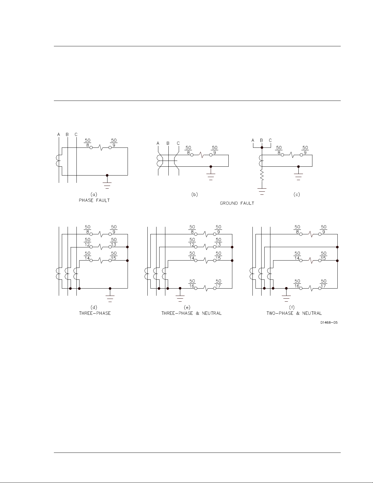
Some applications are illustrated in Figure 1-1.
Figure 1-1. Typical BE1-50 Applications
Ground Fault Detection
BE1-50 relays can be applied to monitor zero sequence currents that are indicative of ground faults. The
most sensitive method of ground fault protection utilizes a single current transformer through which all the
conductors are passed (Figure 1-1b). Another method uses the residual connection of the three-phase
CTs (Figure 1-1d) with the relay set higher than the normal system unbalance. The most direct method is
to place a CT in the neutral of a grounded wye connection for equipment such as power transformers or
generators (Figure 1-1c).
Phase Fault Detection
BE1-50 relays can be used in two ways to detect phase faults. The first method is to place an
instantaneous overcurrent element in each phase with the setting higher than expected load current for
any power system element (Figure 1-1a, d, e, f). The second method is called self-balancing differential
protection (Figure 1-2).
9171000990 Rev F BE1-50 General Information 1-1
Page 10
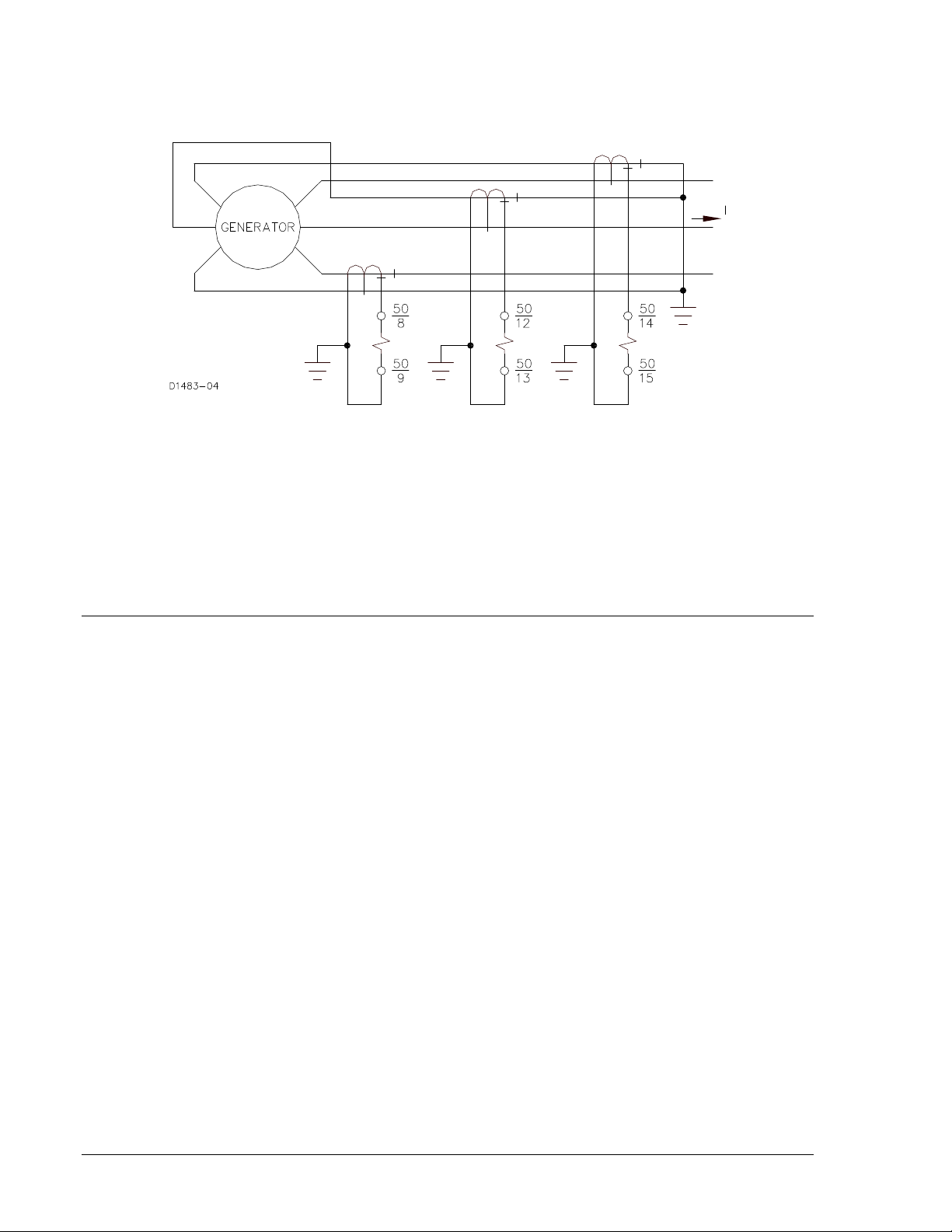
In this application, the two leads of each phase of the protected motor or generator are passed through
the window of the same associated phase current transformer so that the resulting secondary current is
zero under normal operating conditions.
Figure 1-2. Self-Balancing Differential Protection
Combination with Other Protective Devices
Because BE1-50 relays can provide complete phase and ground fault protection in one unit (and with
independent settings for phase and ground), they are often used to supervise other relay functions. In
distance protection, BE1-50 relays can be used to prevent misoperation for light loading conditions by
requiring a minimum current level before enabling the distance relay. As a fault detector, they are
particularly effective because of their sensitivity, speed, and dropout ratio.
MODEL AND STYLE NUMBER
BE1-50 electrical characteristics and operational features are defined by a combination of letters and
numbers that make up the style number. Model number BE1-50 designates the relay as a Basler Electric
Instantaneous Overcurrent Relay. The model number, together with the style number, describes the
options included in a specific device and appears on the front panel, draw-out cradle, and inside the case
assembly.
The style number identification chart for the BE1-50 relay is illustrated in Figure 1-3.
1-2 BE1-50 General Information 9171000990 Rev F
Page 11
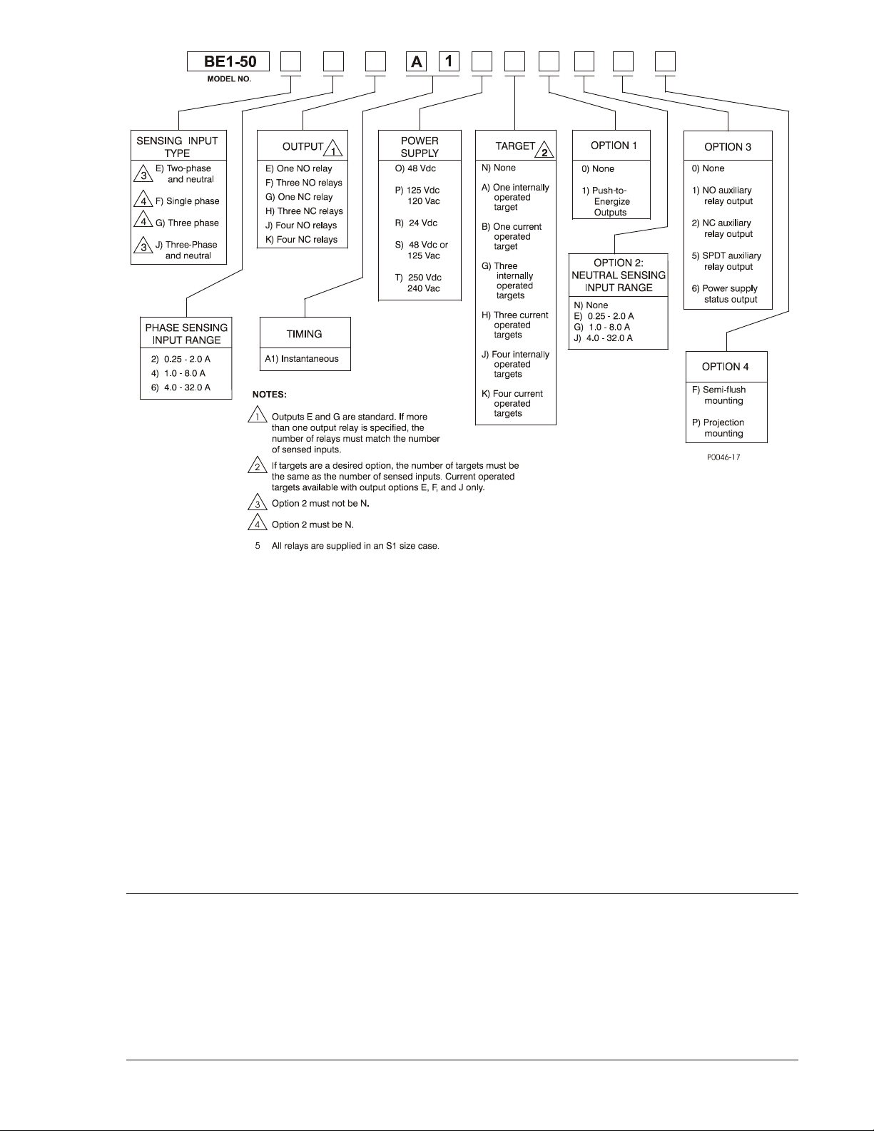
Figure 1-3. BE1-50 Style Identification Chart
Style Number Example
If a BE1-50 relay has a style number of J6J–A1P–J1E1F, the relay has the following features:
J -------- Three-phase-and-neutral current sensing
6 -------- 8.0 to 16.0 A phase sensing input range
J -------- Four output relays with normally open contacts
A1 ------ Instantaneous timing
P -------- Operating power derived from 125 Vdc or 120 Vac
J -------- Four internally operated targets
1 -------- Push-to-energize outputs
E -------- 0.5 to 1.0 A neutral sensing input range
1 -------- One auxiliary output relay with normally open contacts
F -------- Semi-flush mounting case
SPECIFICATIONS
BE1-50 electrical and physical specifications are listed in the following paragraphs.
Current Sensing
Sensing inputs are nominally rated at 50/60 Hz and have a frequency range of 40 to 70 Hz. Current
ratings and sensing burdens depend on the sensing range and power supply type (defined by the style
number), and are shown in Table 1-1.
9171000990 Rev F BE1-50 General Information 1-3
Page 12

Table 1-1. Current Ratings and Sensing Burdens
t
K
I =
where:
Power
Supply
F, G, or H
†
O, P, R, S,
or T
∗ Ratings other than continuous may be calculated using the equation:
Sensing Range
Designation
Actual Sensing
For
Phase
1 D 0.25 - 0.5 A 144 12.0 A 0.75 A 8.5 VA
2 E 0.5 - 1.0 A 144 12.0 A 1.5 A 8.5 VA
3 F 1.0 - 2.0 A 625 25.0 A 3 A 8.5 VA
4 G 2.0 to 4.0 A 2500 50.0 A 6 A 8.5 VA
5 H 4.0 to 8.0 A 10000 100 A 12 A 8.5 VA
6 J 8.0 - 16.0 A 40000 200 A 20 A 9.5 VA
7 K 16.0 - 32.0 A 90000 300 A 20 A 14.0 VA
2 E 0.25 - 2.0 A 10000 100 A 5 A 0.2 VA
4 G 1.0 - 8.0 A 90000 300 A 10 A 0.6 VA
6 J 4.0 - 32.0 A 90000 300 A 20 A 4.8 VA
For
Neutral
Range
the indicated value
K =
the time in seconds
T =
maximum current
I =
K ∗
Maximum Rating 50 or 60 Hz
Second
Current
1
Continuous
Burden Per
Input
† Power Supply types F, G, and H are no longer available.
Pickup Range
Continuously adjustable over the range defined by the style number with independent ranges and
adjustments for each phase and neutral pickup.
Pickup Accuracy
±2% or ±40 mA of pickup setting, whichever is greater.
Dropout
Within 2% of pickup.
Timing
1.5 cycles or less from onset of overcurrent condition. (30 milliseconds at 50 Hz, 25 milliseconds at 60
Hz.)
Output Contacts
Resistive Ratings
120 Vac: Make, break, and carry 7 Aac continuously
250 Vdc: Make and carry 30 Adc for 0.2 s, carry 7 Adc continuously,
break 0.3 Adc
500 Vdc: Make and carry 15 Adc for 0.2 s, carry 7 Adc continuously,
break 0.3 Adc
Inductive Ratings
120 Vac, 125 Vdc, 250 Vdc: Break 0.3 A (L/R = 0.04)
1-4 BE1-50 General Information 9171000990 Rev F
Page 13

Power Supply
Input Voltage
O (midrange)
48 Vdc
24 to 150 Vdc
1.2 W
125 Vdc
24 to 150 Vdc
1.5 W
120 Vac
90 to 132 Vac
19.3 VA
R (low range)
24 Vdc
12 to 32 Vdc ∗
1.3 W
48 Vdc
24 to 150 Vdc
1.2 W
125 Vdc
24 to 150 Vdc
1.5 W
250 Vdc
68 to 280 Vdc
1.7 W
240 Vac
90 to 270 Vac
31.6 VA
Externally powered power supply types are listed in Table 1-2.
Table 1-2. Power Supply Ratings
Type
P (midrange)
S (midrange)
T (high range)
∗ Type R power supply initially requires 14 Vdc to begin operating. Once operating, the input voltage may
be reduced to 12 Vdc and operation will continue.
Target Indicators
Electronically latched, manually reset target indicators are optionally available to indicate closure of the
trip output contacts. Either internally operated or current operated targets may be specified. Internally
operated targets should be selected when normally closed (NC) output contacts are specified.
Current Operated Targets
Minimum Rating: 200 mA flowing through the trip circuit
Continuous Rating: 3 A
1 Second Rating: 30 A
2 Minute Rating: 7 A
Nominal
Input Voltage Range Burden at Nominal
Type Tests
Shock: Withstands 15 G in each of three mutually perpendicular planes
without structural damage or performance degradation.
Vibration: Withstands 2 G in each of three mutually perpendicular planes,
swept over the range of 10 to 500 Hz for a total of six sweeps, 15
minutes each sweep, without structural damage or degradation of
performance.
Dielectric Strength: Tested in accordance with IEC 255-5 and IEEE C37.90. All circuits to
ground: 2,121 Vdc. Input to Output circuits: 1,500 Vac/2,121 Vdc.
Radio Frequency Interference: Maintains proper operation when tested for interference in
accordance with IEEE C37.90.2-1987, Standard Withstand
Capability of Relay Systems to Radiated Electromagnetic
Interference from Transceivers.
Surge Withstand Capability: Qualified to IEEE C37.90.1-1989, Standard Surge Withstand
Capability (SWC) Tests for Protective Relays and Relay Systems.
Physical
Temperature
Operating Range: –40 to 70°C (–40 to 158°F)
Storage Range: –65 to 100°C (–85 to 212°F)
Weight: 17.5 lb (7.76 kg)
Case Size: S1 (Refer to Section 4 for case dimensions.)
9171000990 Rev F BE1-50 General Information 1-5
Page 14

Agency Recognition/Certification
UL Recognition: UL recognized per Standard 508, File E97033
NOTE: Output contacts are not UL recognized for voltages greater
than 250 volts.
GOST-R Certification: GOST-R certified per the relevant standards of Gosstandart of
Russia.
1-6 BE1-50 General Information 9171000990 Rev F
Page 15

SECTION 2 • CONTROLS AND INDICATORS
INTRODUCTION
All BE1-50 controls and indicators are located on the front panel. The controls and indicators are shown in
Figure 2-1 and described in Table 2-1. Figure 2-1 illustrates a relay with the maximum number of controls
and indicators. Your relay may not have all of the controls and indicators shown and described here.
Figure 2-1. BE1-50 Controls and Indicators
Table 2-1. Control and Indicator Descriptions
Locator Description
A
B
C Power Indicator. This red LED lights when operating power is applied to the relay.
D Target Reset Switch. This switch is operated to reset the target indicators.
9171000990 Rev F BE1-50 Controls and Indicators 2-1
Phase Current Adjust. This multi-turn potentiometer sets the pickup point for all phase
overcurrent elements within the relay. Continuously adjustable over the range defined by
the style number.
Neutral Current Adjust. This multi-turn potentiometer sets the pickup point for the neutral
overcurrent element within the relay. Continuously adjustable over the range defined by
the style number.
Page 16

Locator Description
E
F
Target Indicators. These electronically latched red target indicators illuminate when the
corresponding output relay energizes. To ensure proper operation of the current-operated
targets, the current flowing through the trip circuit must be 200 mA or higher. The target
indicators are reset by operating the target reset switch (locator D).
Output Test Pushbuttons. These pushbuttons allow manual actuation of the output relays.
Output relay actuation is achieved by inserting a nonconductive rod through the front
panel access hole.
2-2 BE1-50 Controls and Indicators 9171000990 Rev F
Page 17

SECTION 3 • FUNCTIONAL DESCRIPTION
INTRODUCTION
BE1-50 Instantaneous Overcurrent relays are static devices that respond to the current magnitude of the
monitored circuit. BE1-50 relay functions are illustrated in Figure 3-1 and described in the following
paragraphs.
Figure 3-1. Function Block Diagram
STEP-DOWN TRANSFORMER
Monitored system currents are applied to the primaries of internal current transformers and stepped down
to internal circuit levels. The internal current transformers provide 1,500 V of isolation for the twelve-volt
logic circuits of the relay.
FULL-WAVE RECTIFIERS
Outputs from each step-down transformer are full-wave rectified and applied to resistor networks to
develop voltages that represent the magnitude of the monitored system currents.
RESPONSE CHARACTERISTICS
Input current signals are rectified and passed through a low pass filter. Filtering smoothes out current
spikes and provides a degree of security against operation on short-term transients.
Filtering also smoothes out the harmonic component effects on current signals. Harmonic component
effects are reduced approximately by 1/n where n is the order of the harmonic. For example, the third
harmonic effect is reduced by filtering to 1/3 of what is would be without filtering. With filtering, the
response characteristics are similar to those of electromechanical relays.
9171000990 Rev F BE1-50 Functional Description 3-1
Page 18

PICKUP SETTINGS
A front panel multiple-turn potentiometer controls the pickup setting for all phases. The potentiometer
establishes the reference voltage representative of the system current, which will cause the relay to
respond. On relay styles monitoring neutral current, an independent potentiometer is provided to establish
the pickup level for neutral.
PICKUP COMPARATORS
The magnitude of each monitored current is compared with the appropriate pickup setting. When a pickup
setting is exceeded, a pulse stretcher for that phase (or neutral) is activated.
PULSE STRETCHERS
Because the sensed currents are full-wave rectified and minimally filtered to retain high-speed operation,
the pulse output from the comparators must be extended.
OUTPUTS
Defined by the style number, individual output relays may be provided for each monitored phase (and
neutral). One output relay may serve for all monitored phases (and neutral). In addition, one auxiliary
output relay may be provided that serves for all monitored phases (and neutral).
PUSH-TO-ENERGIZE OUTPUT PUSHBUTTONS
Small pushbutton switches may be provided as an option to allow testing the primary output contacts and
(if present) the auxiliary output contact. To prevent accidental operation, the pushbuttons are recessed
behind the front panel and are depressed by inserting a thin, non-conducting rod through an access hole
in the front panel.
POWER SUPPLY STATUS OUTPUT
The optional power supply status relay has a set of normally closed contacts and energizes when
operating power is applied to the BE1-50. If relay operating power is lost or one side of the power supply
output (+12 Vdc or –12 Vdc) fails, the power supply status relay de-energizes and closes the power
supply status output contacts. If the power supply status output is provided, then the auxiliary contact is
not available.
POWER SUPPLY
Operating power for the relay circuitry is supplied by a wide range, electrically isolated, low-burden power
supply. Power supply operating power is not polarity sensitive. The front panel power LED and power
supply status output indicate when the power supply is operating. Power supply specifications are listed in
Table 1-2.
TARGET INDICATORS
Target indicators are optional components selected when a relay is ordered. The electronically latched
and reset targets consist of red LED indicators located on the relay front panel. A latched target is reset
by operating the target reset switch on the front panel. If relay operating power is lost, illuminated
(latched) targets are extinguished. When relay operating power is restored, the previously latched targets
are restored to their latched state.
A relay can be equipped with either internally operated targets or current operated targets.
Internally Operated Targets
The relay trip outputs are directly applied to drive the target indicators. The indicators are illuminated
regardless of the current level in the trip circuit.
3-2 BE1-50 Functional Description 9171000990 Rev F
Page 19

Current Operated Targets
Current operated targets are triggered by closure of the output contacts and the presence of at least 200
milliamperes of current flowing in the trip circuit.
NOTE
Prior to September 2007, BE1-50 target indicators consisted of magnetically
latched, disc indicators. These mechanically latched target indicators have been
replaced by the electronically latched LED targets in use today.
9171000990 Rev F BE1-50 Functional Description 3-3
Page 20

This page intentionally left blank.
3-4 BE1-50 Functional Description 9171000990 Rev F
Page 21

SECTION 4 • INSTALLATION
INTRODUCTION
BE1-50 relays are shipped in sturdy cartons to prevent damage during transit. Upon receipt of a relay,
check the model and style number against the requisition and packing list to see that they agree. Inspect
the relay for shipping damage. If there is evidence of damage, file a claim with the carrier, and notify your
sales representative or Basler Electric.
If the relay will not be installed immediately, store it in its original shipping carton in a moisture- and dustfree environment. Before placing the relay in service, it is recommended that the test procedures of
Section 5, Testing be performed.
RELAY OPERATING GUIDELINES AND PRECAUTIONS
Before installing or operating the relay, not the following guidelines and precautions.
• For proper current operated target operation, a minimum current of 200 milliamperes must flow
through the output trip circuit.
• If a wiring insulation test is required, remove the connection plugs and withdraw the relay from its
case.
CAUTION
When the connection plugs are removed, the relay is disconnected from the
operating circuit and will not provide system protection. Always be sure that
external operating (monitored) conditions are stable before removing a relay for
inspection, test, or service.
NOTE
Be sure that the relay is hard-wired to earth ground with no smaller than 12 AWG
copper wire attached to the ground terminal on the rear of the case. When the
relay is configured in a system with other devices, it is recommended to use a
separate lead to the ground bus from each device.
MOUNTING
Because the relay is of solid-state design, it does not have to be mounted vertically. Any convenient
mounting angle may be chosen. Relay outline dimensions and panel drilling diagrams are illustrated in
Figures 4-1 through 4-12.
9171000990 Rev F BE1-50 Installation 4-1
Page 22

3.03 (77)
6.06 (154)
0.25 (6) diameter, 4 places
C
L
Cut-Out
0.575
(15)
8.63
(219)
0.552
(14)
5.69 (144)
Outer Edge of Cover
0.480
(12)
8.25
(210)
4.13
(105)
0.480
(12)
P0072-12
Figure 4-1. Panel Cutting/Drilling, Semi-Flush, S1 Case
4-2 BE1-50 Installation 9171000990 Rev F
Page 23

Figure 4-2. S1 Case Dimensions, Rear View, Double Ended, Semi-Flush Mount
9171000990 Rev F BE1-50 Installation 4-3
Page 24

.75
(19.1)
(157.2)
6.19
(49.53)
1.95
10-32 SCREWS
(7.9)
.31
10-32 SCREWS
(102.4)
4.03
4.03
(102.4)
(7.9)
.31
MOUNTING PANEL
(55.75)
2.195
P0066-64
Figure 4-3. S1 Case Dimensions, Side View, Double Ended, Semi-Flush Mount
4-4 BE1-50 Installation 9171000990 Rev F
Page 25

Figure 4-4. S1 Case Dimensions, Rear View, Single Ended, Semi-Flush Mount
9171000990 Rev F BE1-50 Installation 4-5
Page 26

.75
(19.1)
(157.2)
6.19
(49.53)
1.95
10-32 SCREWS
MOUNTING PANEL
(55.75)
2.195
P0066-69
8.06
(204.72)
(7.9)
.31
Figure 4-5. S1 Case Dimensions, Side View, Single Ended, Semi-Flush Mount
4-6 BE1-50 Installation 9171000990 Rev F
Page 27

Figure 4-6. Panel Cutting/Drilling, Double Ended, Projection Mount, S1 Case
9171000990 Rev F BE1-50 Installation 4-7
Page 28

Figure 4-7. S1 Case Dimensions, Rear View, Double Ended, Projection Mount
4-8 BE1-50 Installation 9171000990 Rev F
Page 29

.75
(19.1)
(157.2)
6.19
(49.53)
1.95
10-32 SCREWS
(7.9)
.31
10-32 SCREWS
(102.4)
4.03
4.03
(102.4)
(7.9)
.31
(55.75)
2.195
P0066-67
TERMINAL EXTENSION (TYP.)
FOR DETAILED INSTRUCTIONS,
SEE THE TERMINAL PROJECTION
MOUNTING KIT SUPPLIED.
.25
(6.4)
5/16-18 STUD
2 PLACES
MOUNTING PANEL
Figure 4-8. S1 Case Dimensions, Side View, Double Ended, Projection Mount
9171000990 Rev F BE1-50 Installation 4-9
Page 30
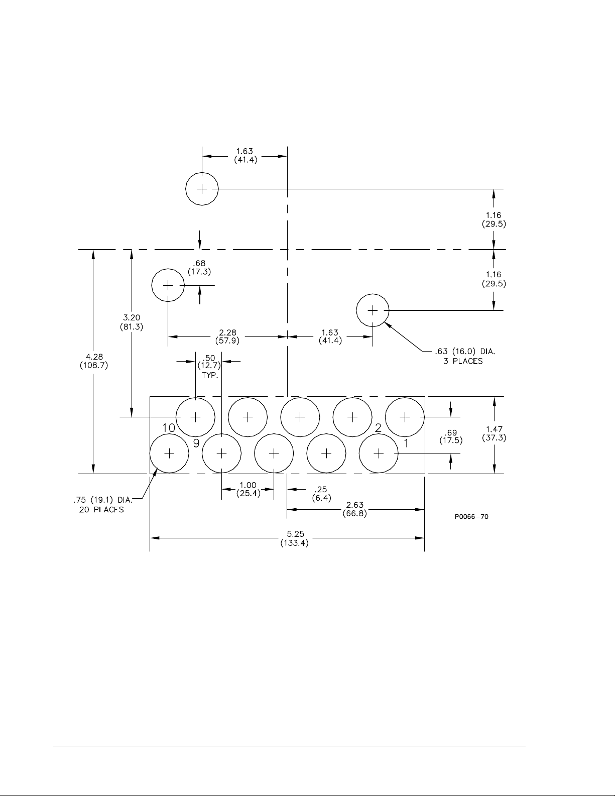
Figure 4-9. Panel Cutting/Drilling, Single Ended, Projection Mount, S1 Case
4-10 BE1-50 Installation 9171000990 Rev F
Page 31

Figure 4-10. S1 Case Dimensions, Rear View, Single Ended, Projection Mount
9171000990 Rev F BE1-50 Installation 4-11
Page 32

(157.2)
6.19
(49.53)
1.95
10-32 SCREWS
MOUNTING PANEL
(55.75)
2.195
P0066-71
TERMINAL EXTENSION (TYP.)
FOR DETAILED INSTRUCTIONS,
SEE THE TERMINAL PROJECTION
MOUNTING KIT SUPPLIED.
.25
(6.4)
5/16-18 STUD
2 PLACES
MOUNTING PANEL
8.06
(204.72)
(7.9)
.31
.75
(19.1)
Figure 4-11. S1 Case Dimensions, Side View, Single Ended, Projection Mount
4-12 BE1-50 Installation 9171000990 Rev F
Page 33

P
0066-
68
Figure 4-12. S1 Case Cover Dimensions, Front View
9171000990 Rev F BE1-50 Installation 4-13
Page 34
CONNECTIONS
Be sure to check the model and style number of a relay before connecting and energizing the relay.
Incorrect wiring may result in damage to the relay. Except where noted, connections should be made with
wire no smaller than 14 AWG.
Typical sensing input connections are shown in Figures 4-13 through 4-16. Typical output connections
are shown in Figures 4-17 and 4-18. Internal wiring diagrams are shown in Figures 4-19 through 4-21.
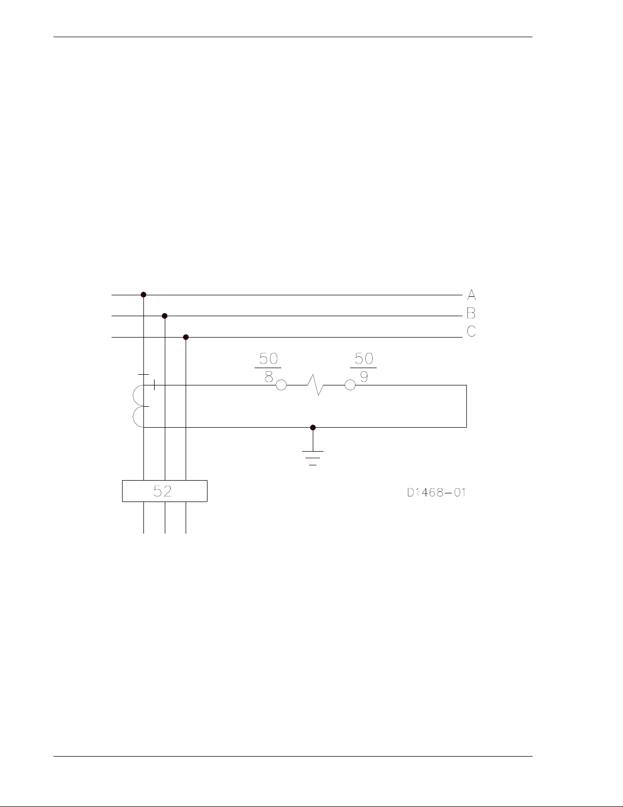
Figure 4-13. Single-Phase Sensing Input Connections
4-14 BE1-50 Installation 9171000990 Rev F
Page 35

Figure 4-14. Three-Phase-and-Neutral Sensing Input Connections
Figure 4-15. Two-Phase-and-Neutral Sensing Input Connections
9171000990 Rev F BE1-50 Installation 4-15
Page 36
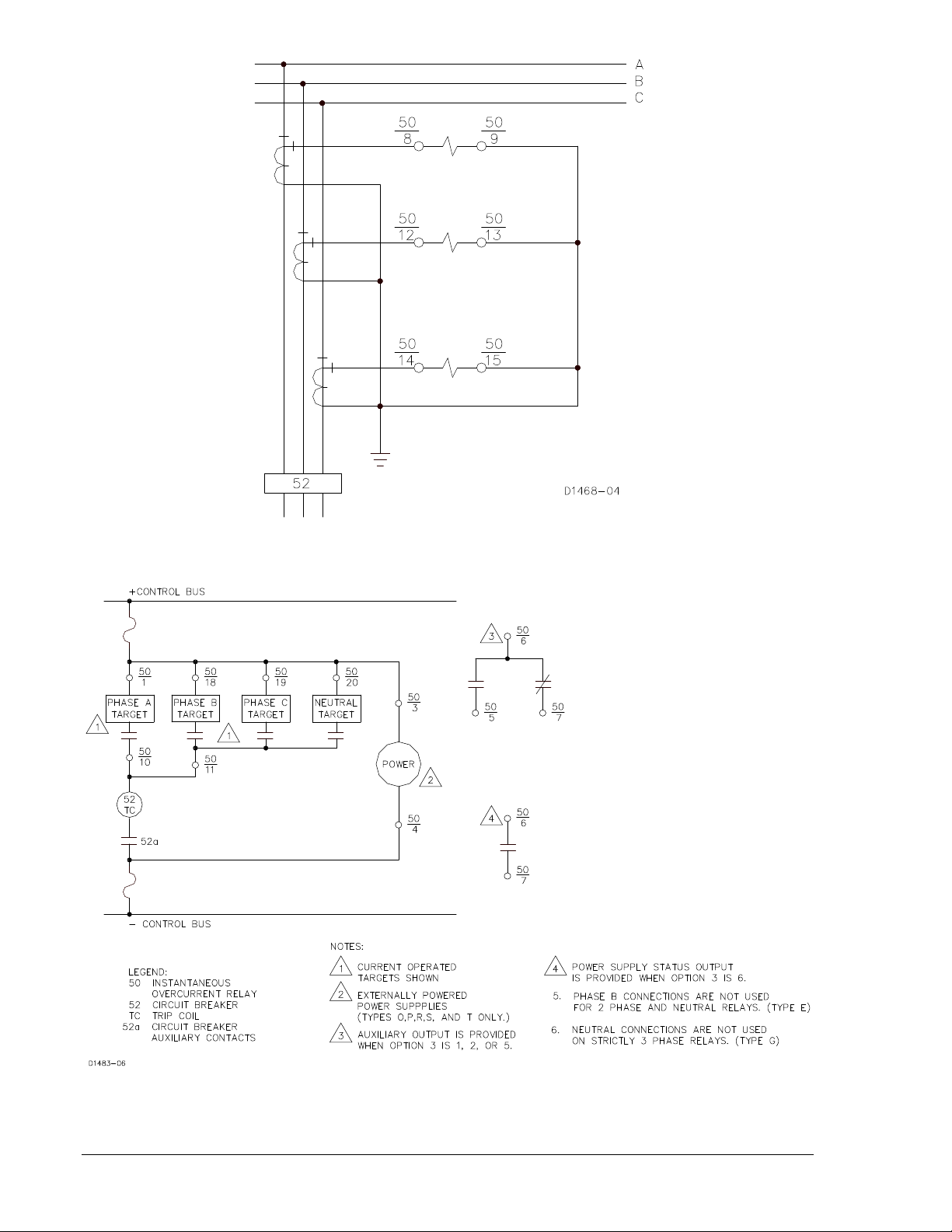
Figure 4-16. Three-Phase Sensing Input Connections
Figure 4-17. Typical Output Connections (Sensing Input Type E or G and Output F or H)
or (Sensing Input Type J and Output J or K)
4-16 BE1-50 Installation 9171000990 Rev F
Page 37

Figure 4-18. Typical Output Connections (Sensing Input Type F and Output E or G)
9171000990 Rev F BE1-50 Installation 4-17
Page 38

Figure 4-19. Typical Internal Connections, Three-Phase-and-Neutral Sensing, Output Type E
4-18 BE1-50 Installation 9171000990 Rev F
Page 39
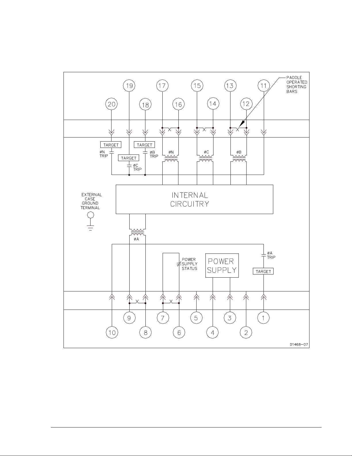
Figure 4-20. Typical Internal Connections, Three-Phase-and-Neutral Sensing, Multiple Output Relays
9171000990 Rev F BE1-50 Installation 4-19
Page 40

Figure 4-21. Typical Internal Connections, Single-Phase, Output E
MAINTENANCE
BE1-50 relays require no preventative maintenance other than a periodic operational check. If the relay
fails to function properly, contact Technical Sales Support at Basler Electric to coordinate repairs.
STORAGE
This device contains long-life electrolytic capacitors. For devices that are not in service (spares in
storage), the life of these capacitors can be maximized by energizing the device for 30 minutes once per
year.
4-20 BE1-50 Installation 9171000990 Rev F
Page 41

SECTION 5 • TESTING
INTRODUCTION
The following procedures verify proper relay operation and calibration.
Results obtained from these procedures may no fall within specified tolerances. When evaluating results,
consider three prominent factors:
• Test equipment accuracy
• Testing method
• External test set components tolerance level
CAUTION
When adjusting for currents higher than 20 amperes AC, do NOT allow sustained
current flow longer than thirty seconds. Allow a minimum one minute cooling time
between applications.
OPERATIONAL TEST
Step 1. Connect the test circuit shown in Figure 5-1. For relay styles with power supply types O, P, R,
S, or T, apply appropriate operating power to terminals 3 and 4. If equipped with power supply
status contacts (option 3-6), verify that these contacts when external power is applied. Remove
input power and verify that the status contacts close. (For relay styles with power supply types
F, G, and H, the relay is powered from the current sensing inputs.)
Figure 5-1. Test Circuit Connection
9171000990 Rev F BE1-50 Testing 5-1
Page 42

Step 2. Turn the phase pickup adjustment fully CCW. For relay styles with target indicators, operate the
manual reset switch to ensure that the targets are reset.
Step 3. Apply sensing current (near zero) and slowly increase the sensed current until the test indicator
changes state.
Result: Current indicated by the ammeter is within two percent of the low end of the sensing
range. If present, the target indicator for the tested phase (or neutral) should be
actuated.
Step 4. Turn the pickup adjustment fully CW. Reset target indicators if present.
Step 5. Apply sensing current (near zero) and slowly increase the sensed current until the test indicator
changes state.
Result: Current indicated by the ammeter is within two percent of the high end of the sensing
range. If present, the target indicator for the tested phase (or neutral) should be
actuated.
Step 6. Repeat Steps 2 through 5 for each phase and neutral as necessary for your style relay. (Neutral
sensing ranges may be different from the phase sensing range.)
5-2 BE1-50 Testing 9171000990 Rev F
Page 43

Page 44

12570 State Route 143
P.A.E. Les Pins
No. 59 Heshun Road Loufeng District (N)
111 North Bridge Road
Highland IL 62249-1074 USA
Tel: +1 618.654.2341
Fax: +1.618.654.2351
email: info@basler.com
67319 Wasselonne Cedex
FRANCE
Tel: +33 3.88.87.1010
Fax: +33 3.88.87.0808
email: franceinfo@basler.com
Suzhou Industrial Park
215122 Suzhou
P.R. CHINA
Tel: +86 512.8227.2880
Fax: +86 512.8227.2887
email: chinainfo@basler.com
15-06 Peninsula Plaza
Singapore 179098
Tel: +65 68.44.6445
Fax: +65 68.44.8902
email: singaporeinfo@basler.com
 Loading...