

Page 1
INSTRUCTION MANUAL
FOR
VOLTAGE PHASE SEQUENCE RELAY
BE1-47N
Publication: 9170400990
Revision: J 03/12
Page 2

Page 3

INTRODUCTION
This instruction manual provides information about the operation and installation of the BE1-47N Voltage
Phase Sequence Relay. To accomplish this, the following information is provided:
General Information and Specifications
Controls and Indicators
Functional Description
Installation
Testing
WARNING!
To avoid personal injury or equipment damage, only qualified personnel should
perform the procedures in this manual.
NOTE
Be sure that the BE1-47N is hard-wired to earth ground with no smaller than
12 AWG copper wire attached to the ground terminal on the rear of the unit
case. When the BE1-47N is configured in a system with other devices, it is
recommended to use a separate lead to the ground bus from each unit.
9170400990 Rev J BE1-47N Introduction i
Page 4

First Printing: September 1985
Printed in USA
© 1985-2012 Basler Electric, Highland Illinois 62249 USA
All Rights Reserved
March 2012
CONFIDENTIAL INFORMATION
of Basler Electric, Highland Illinois, USA. It is loaned for confidential use,
subject to return on request, and with the mutual understanding that it will not
be used in any manner detrimental to the interest of Basler Electric.
It is not the intention of this manual to cover all details and variations in equipment, nor does this manual
provide data for every possible contingency regarding installation or operation. The availability and design
of all features and options are subject to modification without notice. Should further information be
required, contact Basler Electric.
BASLER ELECTRIC
12570 STATE ROUTE 143
HIGHLAND IL 62249 USA
http://www.basler.com, info@basler.com
PHONE +1 618.654.2341 FAX +1 618.654.2351
ii BE1-47N Introduction 9170400990 Rev J
Page 5

REVISION HISTORY
The following information provides a historical summary of the changes made to the BE1-47N instruction
manual (9170400990). Revisions are listed in reverse chronological order.
Manual
Revision and Date
J, 03/12
I
H, 09/07
G, 07/06
F, 02/01
E, 08/98
D, 11/89
C
B
A
—, 09/85
Change
Updated GOST-R statement in Section 1.
Standardized case and cover drawings in Section 4.
Updated Storage statement in Section 4.
This revision letter not used.
Added manual part number and revision to all footers.
Updated power supply burden data in Section 1.
Updated Target Indicator description in Section 3.
Moved contents of Section 7, Manual Change Information to the
manual introduction and deleted Section 7.
Moved contents of Section 6, Maintenance to Section 4 and deleted
Section 6.
Corrected Target options of style chart (added N) None).
Corrected/clarified output contact specifications.
Added Gost R certification statement.
Updated all front panel illustrations to show laser-cut overlay.
Updated the S1 case drawings.
Updated the style chart.
Removed all references to Service Manual 9170400620.
In Specifications:
o Added phase rotation sensitivity
o Updated the dielectric strength information
o Updated the power supply input voltage range and burden data
o Added RFI and UL information
Corrected errors in style chart.
Revised functional description of power supply.
Added outline drawings to cover all mounting options.
Updated manual format.
Negative sequence voltage timing accuracy statement clarified.
Improved wording of test procedures.
Corrected projection-mount case illustrations.
Revision history not available.
Revision history not available.
Revision history not available.
Initial release
9170400990 Rev J BE1-47N Introduction iii
Page 6

iv BE1-47N Introduction 9170400990 Rev J
Page 7

CONTENTS
SECTION 1 GENERAL INFORMATION ................................................................................................ 1-1
Purpose ............................................................................................................................................... 1-1
Application ........................................................................................................................................... 1-1
Phase Rotation Sensitivity ............................................................................................................ 1-1
Model and Style Number..................................................................................................................... 1-1
Style Number Example ................................................................................................................. 1-2
Specifications ...................................................................................................................................... 1-3
Voltage Sensing Input .................................................................................................................. 1-3
Power Supply................................................................................................................................ 1-3
Target Indicators ........................................................................................................................... 1-3
Negative Sequence Voltage ......................................................................................................... 1-3
Undervoltage ................................................................................................................................ 1-4
Overvoltage .................................................................................................................................. 1-4
Output Contacts ............................................................................................................................ 1-5
Type Tests .................................................................................................................................... 1-5
Physical ........................................................................................................................................ 1-5
Agency Recognition/Certification.................................................................................................. 1-5
SECTION 2 CONTROLS AND INDICATORS ....................................................................................... 2-1
Introduction ......................................................................................................................................... 2-1
SECTION 3 FUNCTIONAL DESCRIPTION ........................................................................................... 3-1
Introduction ......................................................................................................................................... 3-1
Voltage Sensing .................................................................................................................................. 3-1
Phase Shifting ..................................................................................................................................... 3-2
Pickup Scaling ..................................................................................................................................... 3-2
Low-Pass Filter ................................................................................................................................... 3-2
Negative Sequence Voltage Comparator ........................................................................................... 3-2
Overvoltage/Undervoltage Comparator .............................................................................................. 3-2
Timing.................................................................................................................................................. 3-2
Outputs ................................................................................................................................................ 3-6
Main Outputs ................................................................................................................................ 3-6
Auxiliary Outputs .......................................................................................................................... 3-6
Power Supply Status Output ........................................................................................................ 3-7
Indicators ............................................................................................................................................. 3-7
Internally Operated Targets .......................................................................................................... 3-6
Current Operated Targets ............................................................................................................ 3-6
Power Supply ...................................................................................................................................... 3-7
Target Indicators ................................................................................................................................. 3-7
Internally Operated Targets .......................................................................................................... 3-7
Current Operated Targets ............................................................................................................ 3-7
SECTION 4 INSTALLATION .................................................................................................................. 4-1
Introduction ......................................................................................................................................... 4-1
Relay Operating Guidelines and Precautions ..................................................................................... 4-1
Mounting ............................................................................................................................................. 4-1
Connections ........................................................................................................................................ 4-9
Maintenance ...................................................................................................................................... 4-12
Storage .............................................................................................................................................. 4-12
9170400990 Rev J BE1-47N Introduction v
Page 8

SECTION 5 TESTING ............................................................................................................................ 5-1
Introduction ......................................................................................................................................... 5-1
Operational Tests ................................................................................................................................ 5-1
Negative Sequence Voltage Pickup and Dropout ........................................................................ 5-1
Overvoltage Pickup and Dropout .................................................................................................. 5-2
Undervoltage Pickup and Dropout ................................................................................................ 5-2
Verification Tests ................................................................................................................................. 5-3
Definite Time Verification .............................................................................................................. 5-3
Inverse Time Verification .............................................................................................................. 5-3
vi BE1-47N Introduction 9170400990 Rev J
Page 9

SECTION 1 • GENERAL INFORMATION
Purpose
BE1-47N Voltage Phase Sequence Relays respond to negative sequence voltage (V2) which results from
a fault or misconnection on a balanced, three-phase system.
Application
BE1-47N relays are designed to protect equipment from damage caused by phase failure, reverse phase
sequence, phase unbalance, undervoltage, or overvoltage.
The relay detects reverse phase connection of lines, transformers, motors, generators, and synchronous
condensers and is often applied in automatic transfer schemes to assure connection of proper phase
rotation as well as voltage conditions. When used in a motor application, the relay provides protection by
preventing motor startup during open-phase or reverse-phase conditions and by tripping the motor off line
for phase unbalance, undervoltage, or overvoltage conditions.
Negative sequence voltage is the result of any unequal phase condition on the source. This can be due to
unequal single-phase loads on the system or unequal transformer impedances between phases. A 1 to
2% level can normally be expected in an industrial supply. Any significant increase above this level can
indicate a power service problem and could lead to serious plant problems. The BE1-47N has the ability
to detect negative sequence voltage levels of this magnitude.
Undervoltage and voltage balance relays have traditionally been applied to protect induction motors from
operating with one phase open. These relays may not reliably detect this condition due to the back-EMF
of the motor on the open phase. However, an induction motor with a starting current of 6 per-unit will
generate a negative sequence voltage of 16% if fully loaded when a fuse opens. The negative sequence
voltage will be somewhat reduced if the motor is not fully loaded. The sensitivity of the BE1-47N and its
insensitivity to frequency allow reliable protection to be applied to motors.
Motor losses and current unbalance increase with the negative-sequence voltage level. The increased
loss due to negative sequence voltage is not a function of motor load but is independent. A machine
operating with 3.5% negative sequence voltage will have its losses increased by 25%. An open fuse on a
power factor correction capacitor bank can result in a significant increase in negative sequence voltage.
The effect of this condition can be costly.
BE1-47N relays can be applied to protect motor buses from an open phase. It can also be applied to
protect critical individual motors, static, and non-rotating loads from the effects of negative sequence
voltage.
A choice of time delay characteristics allows the relay to respond in the desired manner for a wide variety
of transient and fault conditions.
BE1-47N relays may also be used to provide overvoltage and undervoltage protection. A separate time
delay is utilized to prevent shutdown of equipment during minor voltage dips and to permit sequential
operation when the relay is being used in a supervisory capacity.
Phase Rotation Sensitivity
Relays that use phase-to-phase voltage to determine negative sequence are sensitive to phase rotation.
BE1-47N relays are phase rotation sensitive. Unless otherwise noted, all connections shown in this
manual assume ABC rotation.
Model and Style Number
BE1-47N electrical characteristics and operational features are defined by a combination of letters and
numbers that make up the style number. Model number BE1-47N designates the relay as a Basler
Electric Voltage Phase Sequence Relay. The model number, together with the style number, describes
the options included in a specific device and appears on the front panel, draw-out cradle, and inside the
case assembly.
The style number identification chart for the BE1-47N relay is illustrated in Figure 1-1.
9170400990 Rev J BE1-47N General Information 1-1
Page 10
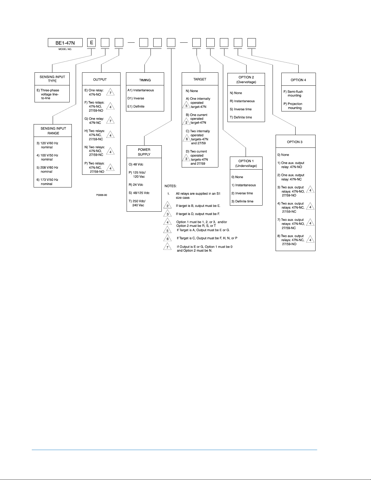
Figure 1-1. BE1-47N Style Identification Chart
Style Number Example
If a BE1-47N relay has a style number of E3F–E1P–A1R0F, the relay has the following features:
E ------- Three-phase, line-to-line voltage sensing
3 -------- 120 Vac, 60 Hz nominal sensing voltage input
F -------- Two output relays with normally open (NO) contacts
E1 ------ Timing characteristic uses definite time delays
P ------- Relay control power is 125 Vdc or 120 Vac, nominal
A ------- One internally operated target indicator
1 -------- Instantaneous undervoltage element
R ------- Instantaneous overvoltage element
0 -------- No auxiliary output relay
F -------- Semi-flush mounting case
1-2 BE1-47N General Information 9170400990 Rev J
Page 11

Specifications
Input Voltage
Range
O (midrange)
48 Vdc
24 to 150 Vdc
4.6 W
125 Vdc
24 to 150 Vdc
4.6 W
120 Vac
90 to 132 Vac
17.5 VA
12 to 32 Vdc ∗
48 Vdc
24 to 150 Vdc
4.6 W
125 Vdc
24 to 150 Vdc
4.6 W
250 Vdc
68 to 280 Vdc
4.6 W
240 Vac
90 to 270 Vac
24.4 VA
BE1-47N electrical and physical specifications are listed in the following paragraphs.
Voltage Sensing Input
Voltage
Nominal: 120 or 208 Vac (60 Hz)
100 or 173 Vac (50 Hz)
Maximum Continuous: 160% of nominal
Frequency
Nominal: 50 or 60 Hz (dictated by relay style)
Range
50 Hz Sensing Input: 45 to 55 Hz
60 Hz Sensing Input: 55 to 65 Hz
Burden: ≤2 VA per phase
Power Supply
Power supply types and specifications are listed in Table 1-1.
Table 1-1. Power Supply Ratings
Type
P (midrange)
R (low range)
S (midrange)
T (high range)
∗ Type R power supply initially requires 14 Vdc to begin operating. Once operating, the input
voltage may be reduced to 12 Vdc and operation will continue.
Nominal
24 Vdc
Input Voltage
Burden at Nominal
4.6 W
Target Indicators
Electronically latched, manually reset target indicators are optionally available to indicate closure of the
trip output contacts. Either internally operated or current operated targets may be specified. Internally
operated targets should be selected when normally-closed (NC) output contacts are specified.
Current Operated Targets
Minimum Rating ......................... 200 mA flowing through the trip circuit
Continuous Rating ...................... 3 A
1 Second Rating ......................... 30 A
2 Minute Rating .......................... 7 A
Negative Sequence Voltage
Pickup
Setting Range ............................ 2 to 32% of nominal
Increment ................................... 2%
Accuracy .................................... ±1 unit of the percent setting of the negative sequence voltage at
nominal frequency (50 or 60 Hz as defined by the style number)
Dropout ............................................. 98% of pickup
9170400990 Rev J BE1-47N General Information 1-3
Page 12

Time Delay
Definite
Setting Range ...................... 0.1 to 9.9 s
Increment ............................. 0.1 s
Accuracy .............................. ±5% or ±50 ms of the time setting
Inverse
Setting Range ...................... 01 to 99
Increment ............................. 1
Accuracy .............................. ±5% or ±50 ms of the indicated time of the selected time-dial curve
illustrated in Figure 3-3
Instantaneous
Delay .................................... <50 ms
Undervoltage
Pickup
Setting Range ............................ 2 to 32% below nominal
Increment ................................... 2%
Accuracy..................................... ±1% of the pickup setting
Dropout ............................................. 98% of pickup
Time Delay
Definite
Setting Range ...................... 0.1 to 9.9 s
Increment ............................. 0.1 s
Accuracy .............................. ±5% of the time setting
Inverse
Setting Range ...................... 01 to 99
Increment ............................. 1
Accuracy .............................. ±5% or ±50 ms of the indicated time of the selected time-dial curve
illustrated in Figure 3-3
Instantaneous
Delay .................................... <50 ms
Overvoltage
Pickup
Setting Range ............................ 2 to 32% above nominal
Increment ................................... 2%
Accuracy..................................... ±1% of the pickup setting
Dropout ............................................. 98% of pickup
Time Delay
Definite
Setting Range ...................... 0.1 to 9.9 s
Increment ............................. 0.1 s
Accuracy .............................. ±5% of the time setting
Inverse
Setting Range ...................... 01 to 99
Increment ............................. 1
Accuracy .............................. ±5% or ±50 ms of the indicated time of the selected time-dial curve
illustrated in Figure 3-3
Instantaneous
Delay .................................... <50 ms
1-4 BE1-47N General Information 9170400990 Rev J
Page 13

Output Contacts
Resistive Ratings
120 Vac ...................................... Make, break, and carry 7 Aac continuously
250 Vdc ...................................... Make and carry 30 Adc for 0.2 s, carry 7 Adc continuously,
break 0.3 Adc
500 Vdc ...................................... Make and carry 15 Adc for 0.2 s, carry 7 Adc continuously,
break 0.3 Adc
Inductive Ratings
120 Vac, 125 Vdc, 250 Vdc ....... Break 0.3 A (L/R = 0.04)
Type Tests
Shock ................................................ Withstands 15 G in each of three mutually perpendicular planes
without structural damage or performance degradation.
Vibration ............................................ Withstands 2 G in each of three mutually perpendicular planes,
swept over the range of 10 to 500 Hz for a total of six sweeps, 15
minutes each sweep, without structural damage or degradation of
performance.
Dielectric Strength ............................ Tested in accordance with IEC 255-5 and IEEE C37.90
All circuits to ground ......... 2,121 Vdc applied for 1 min
Input to output circuits ...... 1,500 Vac or 2,121 Vdc applied for 1 min
Radio Frequency Interference .......... Maintains proper operation when tested for interference in
accordance with IEEE C37.90.2-1987, Standard Withstand
Capability of Relay Systems to Radiated Electromagnetic
Interference from Transceivers.
Surge Withstand Capability .............. Qualified to IEEE C37.90.1-1989, Standard Surge Withstand
Capability (SWC) Tests for Protective Relays and Relay Systems.
Fast Transient ................................... Qualified to IEEE C37.90.1-1989
Impulse ............................................. Qualified to IEC 255-5
Physical
Temperature
Operating Range ........................ –40 to 70°C (–40 to 158°F)
Storage Range ........................... –65 to 100°C (–85 to 212°F)
Weight ............................................. 14 lb (6.35 kg)
Case Size ......................................... S1 (Refer Section 4 for case dimensions.)
Agency Recognition/Certification
UL Recognition ................................. UL recognized per Standard 508, File E97033
NOTE: Output contacts are not UL recognized for voltages greater
than 250 volts.
GOST-R Certification ........................ GOST-R certified per the relevant standards of Gosstandart of
Russia.
9170400990 Rev J BE1-47N General Information 1-5
Page 14

1-6 BE1-47N General Information 9170400990 Rev J
Page 15

SECTION 2 • CONTROLS AND INDICATORS
Locator
Description
A
Power Indicator. This red LED lights when operating power is applied to the relay.
B
Negative Sequence Voltage Controls and Indicator. These elements consist of a pickup
setting of the negative sequence voltage pickup switch.
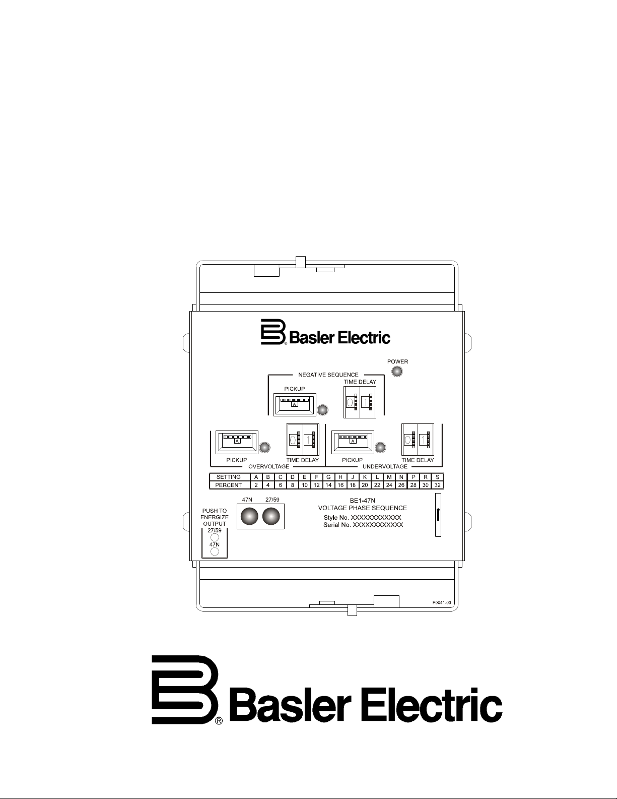
Introduction
All BE1-47N controls and indicators are located on the front panel. The controls and indicators are shown
in Figure 2-1 and described in Table 2-1. Figure 2-1 illustrates a relay with the maximum number of
controls and indicators. Your relay may not have all of the controls and indicators shown and described
here.
Figure 2-1. BE1-47N Controls and Indicators
Table 2-1. Control and Indicator Descriptions
thumbwheel switch, a time delay thumbwheel switch, and a pickup indicator.
The 16-position pickup switch adjusts the negative sequence voltage pickup setpoint.
Switch positions A through S correspond to setpoints ranging from 2 to 32% of the
nominal voltage, in 2% increments. The front panel setting chart (locator D) lists the
9170400990 Rev J BE1-47N Controls and Indicators 2-1
setpoint for each switch position.
Relays with definite or inverse timing have a time delay switch that sets the duration of
timing for negative sequence voltage protection. Instantaneous timing is not useradjustable, so relays with instantaneous timing do not have a time delay switch.
The red pickup LED lights when the level of negative sequence voltage exceeds the
Page 16

Locator
Description
C
Undervoltage Controls and Indicator. These elements consist of a pickup thumbwheel
switch, a time delay thumbwheel switch, and a pickup indicator. Undervoltage elements
setting of the undervoltage pickup switch.
D
Setting Chart. To aid in setting pickup levels, this chart lists the percent difference (from
and undervoltage pickup setting switches.
E
Target Reset Switch. This switch is operated to reset the target indicators.
panel access holes.
G
Target Indicators. The electronically latched red target indicators illuminate when the
indicators are reset by operating the target reset switch (locator E).
H
Overvoltage Controls and Indicator. These elements consist of a pickup thumbwheel
setting of the overvoltage pickup switch.
are present only if option 1 of the relay style number is 1, 2, or 3.
The 16-position pickup switch adjusts the undervoltage pickup setpoint. Switch positions
A through S correspond to setpoints ranging from 2 to 32% below the nominal (singlephase) voltage, in 2% increments. The front panel setting chart (locator D) lists the
setpoint for each switch position.
Relays with definite or inverse timing have a time delay switch that sets the duration of
timing for undervoltage protection. Instantaneous timing is not user-adjustable, so relays
with instantaneous timing do not have an undervoltage time delay switch.
The red pickup LED lights when the level of (single-phase) voltage decreases below the
nominal) setting for each lettered position of the negative sequence voltage, overvoltage,
F Output Test Pushbuttons. These pushbuttons allow manual actuation of the output relays.
Output relay actuation is achieved by inserting a nonconductive rod through the front
corresponding output relay energizes. To ensure proper operation of current-operated
targets, the current flowing through the trip circuit must be 200 mA or higher. Target
switch, a time delay thumbwheel switch, and a pickup indicator. Overvoltage elements
are present only if option 2 of the relay style number is R, S, or T.
The 16-position pickup switch adjusts the overvoltage pickup setpoint. Switch positions A
through S correspond to setpoints ranging from 2 to 32% above the nominal (singlephase) voltage, in 2% increments. The front panel setting chart (locator D) lists the
setpoint for each switch position.
Relays with definite or inverse timing have a time delay switch that sets the duration of
timing for overvoltage protection. Instantaneous timing is not user-adjustable, so relays
with instantaneous timing do not have an overvoltage time delay switch.
The red pickup LED lights when the level of (single-phase) voltage increases above the
2-2 BE1-47N Controls and Indicators 9170400990 Rev J
Page 17

SECTION 3 • FUNCTIONAL DESCRIPTION
Sensing Input Option
Nominal Voltage
Frequency
3
120 Vac
60 Hz
4
100 Vac
50 Hz
5
208 Vac
60 Hz
6
173 Vac
50 Hz
V
C
TARGET
47N
POWER SUPPLY
STATUS
D2818-12
07-30-98
V
B
V
A
PHASE
SHIFT
PICKUP
SCALING
LOW
PASS
FILTER
REFERENCE
LEVEL
NEGATIVE
SEQUENCE
VOLTAGE
COMPARATOR
AND
47N
AUX.
TIMING
TARGET
27/59
AUX.
OR
TIMING
TIMING
POWER
SUPPLY
SENSOR
59
27
UNDERVOLTAGE
COMPARATOR
UNDERVOLTAGE
PICKUP
OVERVOLTAGE
PICKUP
OVERVOLTAGE
COMPARATOR
LOW
PASS
FILTER
POWER
SUPPLY
SENSOR
POWER
TO INTERNAL
CIRCUITRY
OPERATING
POWER
V
2
SEQUENCE
FILTER
Introduction
BE1-47N relay functions are illustrated in Figure 3-1 and described in the following paragraphs.
Figure 3-1. Function Block Diagram
Voltage Sensing
One of two nominal voltage levels may be specified for a system frequency of 50 hertz or 60 hertz.
Voltage sensing input options are summarized in Table 3-1.
Table 3-1. Voltage Sensing Input Options
Three-phase system voltage is supplied to internal potential transformers (PTs). These PTs are an
integral part of the sequence filter and provide isolation, step-down scaling, and phasor summation to
eliminate the zero-sequence component of the sensed voltages.
9170400990 Rev J BE1-47N Functional Description 3-1
Page 18

Phase Shifting
Timing Characteristic
Instantaneous
Inverse
Definite
Undervoltage (27)
xxx-xxx-x1xxx
xxx-xxx-x2xxx
xxx-xxx-x3xxx
Negative Sequence Voltage (47N)
xxx-A1x-xxxxx
xxx-D1x-xxxxx
xxx-E1x-xxxxx
Overvoltage (59)
xxx-xxx-xxRxx
xxx-xxx-xxSxx
xxx-xxx-xxTxx
The respective secondary voltages are phase shifted ±45° each, with respect to signal ground and then
summed to nullify the positive sequence component.
Pickup Scaling
The resolved negative sequence voltage (V2) ac signal is then applied to the pickup scaling network
(switch S1 and its associated resistors). The pickup network establishes per-unit (PU) values of negative
sequence voltage for the comparison and timing functions.
Low-Pass Filter
The sensing circuits for negative sequence voltage, overvoltage, and undervoltage are designed to
operate on the fundamental frequencies of 50 or 60 hertz. The low-pass filter passes the fundamental
frequencies and attenuates the higher frequencies.
Negative Sequence Voltage Comparator
The proportionate negative sequence (V2) signal is compared to a reference level. When the level of the
per-unit negative sequence voltage exceeds the reference level, the pickup indicator lights and timing is
initiated.
Overvoltage/Undervoltage Comparator
Optional single-phase overvoltage and undervoltage circuits operate on the voltage magnitude. The
single-phase ac signal is low-pass filtered and passed to the respective comparator where it is compared
to the pickup settings for each circuit. If either pickup setting has been exceeded (overvoltage or undervoltage), the appropriate LED lights and timing is initiated.
Timing
One of three timing characteristics is available for each of the three protection functions: definite, inverse,
or instantaneous. The timing characteristic may be independently selected for each protection function.
Table 3-2 identifies the timing style selections for negative sequence voltage, undervoltage, and overvoltage protection.
Table 3-2. Timing Characteristic Style Number Selections
Protection Function
Definite timing is adjustable from 0.1 to 9.9 seconds in increments of 0.1 seconds.
The response time of instantaneous timing is less than 50 milliseconds. When the timing characteristic for
a protection function is definite or inverse and the time delay setting is 00, instantaneous timing is
achieved.
Inverse timing is adjustable from 01 to 99 in increments of 1 (see Figures 3-2 through 3-4 for the inverse
time characteristic curves). When evaluating inverse curves for overvoltage or undervoltage protection,
note that timing is based on the percent difference from the system’s nominal voltage. For example, refer
to Figure 3-4. If the monitored voltage is at a level of 18% below system nominal, the portion of the curves
below 18% (e.g., 13%, 8%, etc.) has no effect on the timing characteristic. In other words, the timing
curve beginning is dependent upon the monitored voltage percent difference from the system’s nominal
voltage. Inverse timing characteristics preceding this defined point are nonexistent.
3-2 BE1-47N Functional Description 9170400990 Rev J
Page 19

MULTIPLES OF PICK-UP SETTING
.05
.01
.1
.5
1
10
5
50
100
1000
500
MULTIPLES OF PICK-UP SETTING
TIME IN SECONDS
1.0 2.0 3.0 4.0 5.0 6.0 7.0 8.0 9.0
L
A
I
D
E
M
I
T
01
02
03
05
07
10
20
30
40
50
60
80
99
D2818-17
07-31-98
Figure 3-2. Negative Sequence Voltage Inverse Time Characteristic Curves
9170400990 Rev J BE1-47N Functional Description 3-3
Page 20

Figure 3-3. Undervoltage Inverse Time Characteristic Curves
3-4 BE1-47N Functional Description 9170400990 Rev J
Page 21

Figure 3-4. Overvoltage Inverse Time Characteristic Curves
9170400990 Rev J BE1-47N Functional Description 3-5
Page 22

Outputs
Output
Configuration
NO
NC
E
47N
47N
27/59
G
47N
47N
27/59
47N
27/59
47N
27/59
Output
Configuration
NO
NC 0 N/A
1
47N
2
47N
47N
27/59
4 47N
27/59
47N
27/59
47N
27/59
BE1-47N outputs consist of the main, tripping output relays, auxiliary output relays, and a power supply
status output relay.
Main Outputs
Output relays, rated for tripping duty, are provided for each protection function. Normally open (NO) or
normally closed (NC) relay contacts may be specified for each protection function. Table 3-3 lists the
possible output relay configurations.
Table 3-3. Main Output Contact Configurations
Output Option
F
H
N
P
Protection
Function
Auxiliary Outputs
Auxiliary output relays that operate at the same time as the main output relays are also available (style
chart option 3). Table 3-4 lists the possible auxiliary output relay configurations.
Table 3-4. Auxiliary Output Contact Configurations
Style Chart
Option 3
Protection
Function
3-6 BE1-47N Functional Description 9170400990 Rev J
3
7
8
Page 23

Power Supply Status Output
The power supply status relay has a set of normally closed contacts and energizes when operating power
is applied to the BE1-47N. If relay operating power is lost or either side of the power supply output (+12
Vdc or –12 Vdc) fails, the power supply status relay de-energizes and opens the power supply status
output contacts.
Indicators
LEDs indicate power supply status and protection function pickup.
The power LED lights when operating power is applied to the relay and the relay power supply is
operating normally.
One LED is provided for each protection function. An LED lights when the function’s setpoint is exceeded
and the protection function is timing toward a trip.
Power Supply
Operating power for the relay circuitry is supplied by a wide range, electrically isolated, low-burden power
supply. Power supply operating power is not polarity sensitive. The front panel power LED and power
supply status output indicate when the power supply is operating. Power supply specifications are listed in
Table 1-1.
Target Indicators
Target indicators are optional components selected when a relay is ordered. The electronically latched
and reset targets consist of red LED indicators located on the relay front panel. A latched target is reset
by operating the target reset switch on the front panel. If relay operating power is lost, any illuminated
(latched) targets are extinguished. When relay operating power is restored, the previously latched targets
are restored to their latched state.
A relay can be equipped with either internally operated targets or current operated targets.
Internally Operated Targets
The relay trip outputs are directly applied to drive the appropriate target indicator. Each indicator is
illuminated regardless of the current level in the trip circuit.
Current Operated Targets
A current operated target is triggered by closure of the corresponding output contact
at least 200 milliamperes of current flowing in the trip circuit.
NOTE
Prior to September 2007, BE1-47N target indicators consisted of magnetically
latched, disc indicators. These mechanically latched target indicators have
been replaced by the electronically latched LED targets in use today.
the presence of
and
9170400990 Rev J BE1-47N Functional Description 3-7
Page 24

3-8 BE1-47N Functional Description 9170400990 Rev J
Page 25

SECTION 4 • INSTALLATION
When the relay is configured in a system with other devices, it is
Introduction
BE1-47N relays are shipped in sturdy cartons to prevent damage during transit. Upon receipt of a relay,
check the model and style number against the requisition and packing list to see that they agree. Inspect
the relay for shipping damage. If there is evidence of damage, file a claim with the carrier, and notify your
sales representative or Basler Electric.
If the relay will not be installed immediately, store it in its original shipping carton in a moisture- and dustfree environment. Before placing the relay in service, it is recommended that the test procedures of
Section 5, Testing be performed.
Relay Operating Guidelines and Precautions
Before installing or operating the relay, note the following guidelines and precautions.
• For proper current operated target operation, a minimum current of 200 milliamperes must flow
through the output trip circuit.
• If a wiring insulation test is required, remove the connection plugs and withdraw the relay from its
case.
CAUTION
When the connection plugs are removed, the relay is disconnected from the
operating circuit and will not provide system protection. Always be sure that
external operating (monitored) conditions are stable before removing a relay
for inspection, test, or service.
NOTE
Be sure that the relay is hard-wired to earth ground with no smaller than 12
AWG copper wire attached to the ground terminal on the rear of the case.
recommended to use a separate lead to the ground bus from each device.
Mounting
Because the relay is of solid-state design, it does not have to be mounted vertically. Any convenient
mounting angle may be chosen.
Relay outline dimensions and panel drilling diagrams are shown in Figures 4-1 through 4-7. Dimensions
are shown in inches with millimeters in parenthesis.
9170400990 Rev J BE1-47N Installation 4-1
Page 26

Figure 4-1. Panel Cutting/Drilling, Semi-Flush, S1 Case
4-2 BE1-47N Installation 9170400990 Rev J
Page 27

Figure 4-2. S1 Case Dimensions, Rear View, Double Ended, Semi-Flush Mount
9170400990 Rev J BE1-47N Installation 4-3
Page 28

.75
(19.1)
(157.2)
6.19
(49.53)
1.95
10-32 SCREWS
(7.9)
.31
10-32 SCREWS
(102.4)
4.03
4.03
(102.4)
(7.9)
.31
MOUNTING PANEL
(55.75)
2.195
P0066-64
Figure 4-3. S1 Case Dimensions, Side View, Double Ended, Semi-Flush Mount
4-4 BE1-47N Installation 9170400990 Rev J
Page 29

Figure 4-4. Panel Cutting/Drilling, Double Ended, Projection Mount S1 Case
9170400990 Rev J BE1-47N Installation 4-5
Page 30

Figure 4-5. S1 Case Dimensions, Rear View, Double Ended, Projection Mount
4-6 BE1-47N Installation 9170400990 Rev J
Page 31

.75
(19.1)
(157.2)
6.19
(49.53)
1.95
10-32 SCREWS
(7.9)
.31
10-32 SCREWS
(102.4)
4.03
4.03
(102.4)
(7.9)
.31
(55.75)
2.195
P0066-67
TERMINAL EXTENSION (TYP.)
FOR DETAILED INSTRUCITONS,
SEE THE TERMINAL PROJECTION
MOUNTING KIT SUPPLIED.
.25
(6.4)
5/16-18 STUD
2 PLACES
MOUNTING PANEL
Figure 4-6. S1 Case Dimensions, Side View, Double Ended, Projection Mount
9170400990 Rev J BE1-47N Installation 4-7
Page 32

P0066-68
Figure 4-7. S1 Case Cover Dimensions, Front View
4-8 BE1-47N Installation 9170400990 Rev J
Page 33

Connections
47N
10
52a
1
47N
47N
T
52
TC
TARGET
47N
3
4
47N
27/59
2
TARGET
27/59
T
27/59
5
POWER
-DC
+DC
CONTROL CIRCUIT
LEGEND:
47N
27/59
52a
52 TC
T
VOLTAGE PHASE SEQUENCE
UNDER/OVERVOLTAGE
BREAKER AUXILIARY CONTACTS
BREAKER TRIP COIL
TIMED
POWER
SUPPLY
STATUS
47N
12
47N
11
11
47N
12
47N
OR OR
27/59
20
27/59
19
19
27/59
20
27/59
(47N) (27/59)
16
17
AUXILIARY CONTACTS
P0066-91
Be sure to check the model and style number of a relay before connecting and energizing the relay.
Incorrect wiring may result in damage to the relay. Except where noted, connections should be made with
wire no smaller than 14 AWG.
Typical external connections are shown in Figures 4-8 and 4-9. Typical internal connections are shown in
Figure 4-10.
9170400990 Rev J BE1-47N Installation 4-9
Figure 4-8. Control Circuit Diagram
Page 34

MOTOR
52
A
B
C
47N
8
7
47N
6
47N
A
B
C
WYE CONNECTED
07-29-98
D1721-01
DELTA CONNECTED
C
B
A
47N
6
47N
7
8
47N
C
B
A
52
MOTOR
Figure 4-9. Sensing Input Connections
4-10 BE1-47N Installation 9170400990 Rev J
Page 35

19 17
15
13 11
EXTERNAL
CASE
GROUND
TERMINAL
20
27/59
AUX.
OVER/
UNDER
VOLTAGE
POWER
SUPPLY
STATUS
16
18
INTERNAL CIRCUITRY
NEGATIVE SEQUENCE
14
12
47N
AUX.
27/59
TARGET
POWER
SUPPLY
9
7
5
3
47N
TARGET
TRIP
1
ØB
10 8
6
ØAØC
4
2
P0066-92
Figure 4-10. Typical Internal Connection Diagram
9170400990 Rev J BE1-47N Installation 4-11
Page 36

Maintenance
BE1-47N relays require no preventative maintenance other than a periodic operational check. If the relay
fails to function properly, contact Technical Sales Support at Basler Electric to coordinate repairs.
Storage
This device contains long-life electrolytic capacitors. For devices that are not in service (spares in
storage), the life of these capacitors can be maximized by energizing the device for 30 minutes once per
year.
4-12 BE1-47N Installation 9170400990 Rev J
Page 37

SECTION 5 • TESTING
120
3
1
2
2
∠∝=
∝+∝+= whereVVVV
CBA
∝+∝+=
CABCAB
VVVV
LL
2
2
3
1
Introduction
The following procedures verify proper relay operation and calibration.
Results obtained from these procedures may not fall within specified tolerances. When evaluating results,
consider three prominent factors:
• Test equipment accuracy
• Testing method
• External test set components tolerance level
Operational Tests
Operational tests include pickup and dropout of negative sequence voltage protection, overvoltage
protection, and undervoltage protection.
Negative Sequence Voltage Pickup and Dropout
BE1-47N accuracy verification requires a simultaneous test of the three phases. Such a comprehensive
test involves careful monitoring of all phase voltages and phase angles, and the calculation of the
negative sequence voltage values. However, it is possible to obtain confirmation of the essential integrity
of the relay without resorting to methods that are more suited to a laboratory.
Accordingly, the following single-phase verification test is offered as an adequate accuracy and calibration
test that is easy to set up and perform.
1. Adjust the Negative Sequence Pickup switch to the K (20%) position.
2. As shown in Figure 5-1, short-circuit or jumper case terminals 7 (B-phase) and 8 (C-phase).
3. Using Table 5-1 as a guide, apply voltage, at nominal frequency, to case terminal 6 (A-phase) and 7
(phases B and C). The Negative Sequence Pickup LED should light.
Table 5-1. Negative-Sequence Test Voltage
Sensing Input Range Voltage Input
3) 120 Vac, 60 Hz 41.57 Vac +2.08 Vac, 60 Hz
4) 100 Vac, 50 Hz 34.64 Vac +1.73 Vac, 50 Hz
5) 208 Vac, 60 Hz 72.05 Vac +3.60 Vac, 60 Hz
6) 173 Vac, 50 Hz 59.93 Vac +3.00 Vac, 50 Hz
4. Vary the input to verify the setting.
5. Lower the input voltage until the pickup LED turns off. Record the input voltage. Dropout should be
within 2% of the pickup value (i.e., input voltage at time of pickup, LED on).
Further pickup settings may be verified at this time. The following formulas determine the input
voltages, based on sensing range, which will cause the pickup LED to light.
Equation 5-1
For line-to-line voltage:
Equation 5-2
9170400990 Rev J BE1-47N Testing 5-1
Page 38

If VBC = 0 Vac (Short phase B to Phase C)
( )
( )
[ ]
( ) ( )
[ ]
( ) ( )
[ ]
( )
[ ]
30
3
303
3
1
300101
3
1
1801120101
3
1
1800
3
1
2
2
−∠=
−∠=
∠+∠=
∠×∠+∠=
∠∝+∝+=
AB
AB
AB
AB
ABABLL
V
V
V
V
VV
V
NPU
V
AB
VV××=
32
( )
( )
( )
Then V
= VAC = –VCA OR VCA = –VAB ∠0° = VAB ∠180°
AB
Substituting into Equation 5-2:
V
V
2
PU
LL
==
V
N
2
30
V
−∠
AB
3
V
N
Equation 5-3
Where V
Solving for V
Magnitude
= 120 V for sensing input range 3 or 208 V for sensing input range 5
N
:
AB
Example:
20% V
For 120 V nominal, V
V
V
= 0.2 per unit V2 = 0.2 per unit V2 (with phase B shorted to phase C)
2
= 120
N
AB
= 41.569 Vac when phase input B is shorted to C
AB
12032.0=
6. Test the other phases by repeating the previous steps while shorting different phase pairs.
Overvoltage Pickup and Dropout
1. Adjust the Overvoltage Pickup switch to the E (10%) position.
2. Apply 1.10 times the nominal input voltage (110%) across case terminals 7 (B-phase) and 8 (Cphase). The Overvoltage Pickup LED should light.
3. Vary the input voltage to confirm the pickup value.
4. Lower the input voltage until the Overvoltage Pickup LED turns off. Record the input value. Dropout
should be within 2.0% of the pickup value (i.e., input voltage at time of pickup, LED on).
Undervoltage Pickup and Dropout
1. Adjust the Undervoltage Pickup switch to the E (10%) position.
2. Apply 0.90 times the nominal input voltage (90%) across case terminals 7 (B-phase) and 8 (C-phase).
The Undervoltage Pickup LED should light.
3. Vary the input voltage to confirm the pickup value.
5-2 BE1-47N Testing 9170400990 Rev J
Page 39

4. Raise the input voltage until the Undervoltage Pickup LED turns off. Record the input value. Dropout
should be within 2.0% of the pickup value (i.e., input voltage at time of pickup, LED on).
Verification Tests
Verification tests consist of definite time verification and inverse time verification.
Definite Time Verification
The definite time circuitry for the negative sequence voltage (47N), overvoltage (59), and undervoltage
(27) functions operates similarly and can be tested using the same philosophy. In order to reduce the
amount of redundant procedural steps, only the overvoltage function is addressed here.
1. Connect the test setup as indicated in Figure 5-2.
2. Adjust the Overvoltage Time Delay switch to 33.
3. Adjust the Overvoltage Pickup switch to the A (2%) position.
4. Connect the voltage source to case terminals 7 (A-phase) and 8 (C-phase) and adjust the voltage
source to 1.20 times the nominal input value (120%).
5. Close switch S1 to initiate the timer. The Overvoltage Pickup LED will light and the timer should time
out at 3.3 seconds ±5%.
Inverse Time Verification
Due to the similarities in inverse timing for the functions of this relay, only the negative sequence function
is addressed here. The remaining functions can be verified using the same test philosophy.
1. Connect the test setup as indicated in Figure 5-1.
2. Adjust the Negative Sequence Pickup switch to the B (4%) position. Adjust the Negative Sequence
Time Delay switch to 10.
3. Short or jumper case terminals 7 (B-phase) and 8 (C-phase).
4. Using Table 5-2 as a guide, apply voltage at case terminals 6 (A-phase) and 7 (C-phase). Note that
the input voltage values are two times the actual pickup value.
Table 5-2. Inverse Time Test Voltage
Sensing Input Range Voltage Input
3) 120 Vac, 60 Hz 16.628 Vac +0.17 Vac, 60 Hz
4) 100 Vac, 50 Hz 13.856 Vac +0.14 Vac, 50 Hz
5) 208 Vac, 60 Hz 28.80 Vac +0.29 Vac, 60 Hz
6) 173 Vac, 50 Hz 24.00 Vac +0.24 Vac, 50 Hz
5. Measure and record the interval from initiate to contact closure at case terminals 1 and 10. The 47N
inverse time should be 5.96 +0.298 seconds.
Further points on the inverse time curves may be verified using the same philosophy. Input voltage
values for pickup may be obtained using the equations mentioned previously.
9170400990 Rev J BE1-47N Testing 5-3
Page 40

1
10
47N
27/59
5
2
8
6
7
43
ØC
ØB
ØA
TO STOP
TIMER
EXTERNAL
POWER
SOURCE
V
TO START
TIMER
07-29-98
D2818-09
S1
JUMPER
1
10
47N
27/59
5
2
8
6
7
43
ØC
ØB
ØA
TO STOP
TIMER
SPECIFIED
OPERATING
POWER
V
V
NOMINAL V NOMINAL V
+
FAULT V
TO START
TIMER
07-29-98
D2818-10
S1
Figure 5-1. Test Circuit Diagram (47N)
5-4 BE1-47N Testing 9170400990 Rev J
Figure 5-2. Test Circuit Diagram (27, 59)
Page 41

Page 42

®
12570 State Route 143
Highland IL 62249-1074 USA
www.basler.com, info@basler.com
Phone +1 618.654.2341 Fax +1 618.654.2351
 Loading...